

Page 1
SmartSensor Advance
A
A
BDC
B
1
3
4
2
INSTALLER QUICK-REFERENCE GUIDE
Introduction
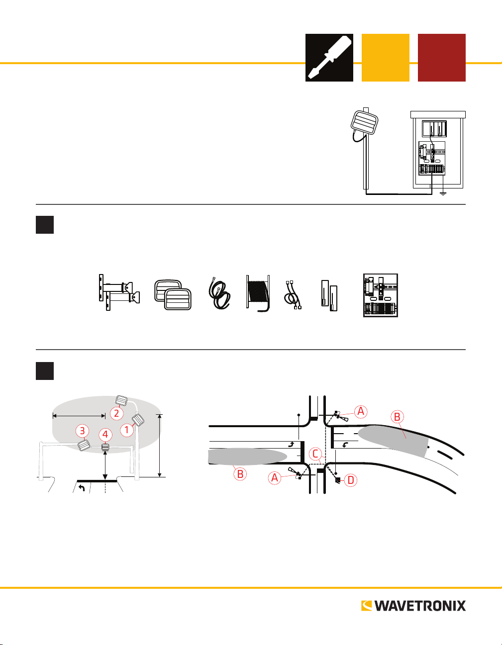
Complete steps 1–9 to integrate the Wavetronix Advance detection system
into a signalized intersection. If you need technical support or have questions, please contact Wavetronix Technical Services at (801) 734-7200. For
more information, see the SmartSensor Advance User Guide.
Ensure that all necessary components are available
1
e components below, all of which can be ordered from Wavetronix, may be needed to install your sensor;
for more information on any of these, see the Wavetronix product catalog.
Mount
brackets
Identify sensor’s location and pull homerun cable through conduit
2
50 feet
17 feet
Suggested mounting locations:
1 Near-side vertical pole
2 Near-side luminaire
3 Back-side opposing mast arm
4 Front-side mast arm
www.wavetronix.com
801.734.7200
Sensors Sensor
cables
30 feet
Homerun
cable
Patch
cords
Sensor detection coverage:
A SmartSensor Advance
B Detection coverage
C Homerun cable
D Trac cabinet
cards
Rack
Preassembled
backplate
Page 2
Select the mounting height, attach and point at target
3
1 Determine the mounting height (between 17 and 40 feet is recommended; typical mounting height is
about 25 feet).
Height (ft / m)
17 / 5.2 20 / 6.1 25 / 7.6 30 / 9.1 40 / 12.2
0 / 0 40 / 12.2 45 / 13.7 55 / 16.8 60 / 18.3 75 / 22.9
5 / 1.5 45 / 13.7 45 / 13.7 60 / 18.3 65 / 19.8 80 / 24.4
10 / 3 50 / 15.2 50 / 15.2 60 / 18.3 65 / 19.8 80 / 24.4
15 / 4.6 50 / 15.2 55 / 16.8 65 / 19.8 70 / 21.3 80 / 24.4
20 / 6.1 55 / 16.8 55 / 16.8 65 / 19.8 75 / 22.9 90 / 2 7.4
25 / 7.6 60 / 18.3 65 / 19.8 65 / 19.8 75 / 22.9 90 / 27. 4
30 / 9.1 65 / 19.8 70 / 21.3 75 / 22.9 80 / 24.4 95 / 28.9
Oset (ft / m)
35 / 10.7 70 / 21.3 75 / 22.9 85 / 25.9 85 / 25.9 95 / 28.9
40 / 12.2 80 / 24.4 90 / 2 7.4 90 / 2 7.4 95 / 28.9 100 / 30.4
45 / 13.7 95 / 28.9 100 / 30.4 100 / 30.4 100 / 30.4 105 / 32
50 / 15.2 100 / 30.4 100 / 30.4 105 / 32 110 / 33.5 120 / 36.6
Point sensor at target
4
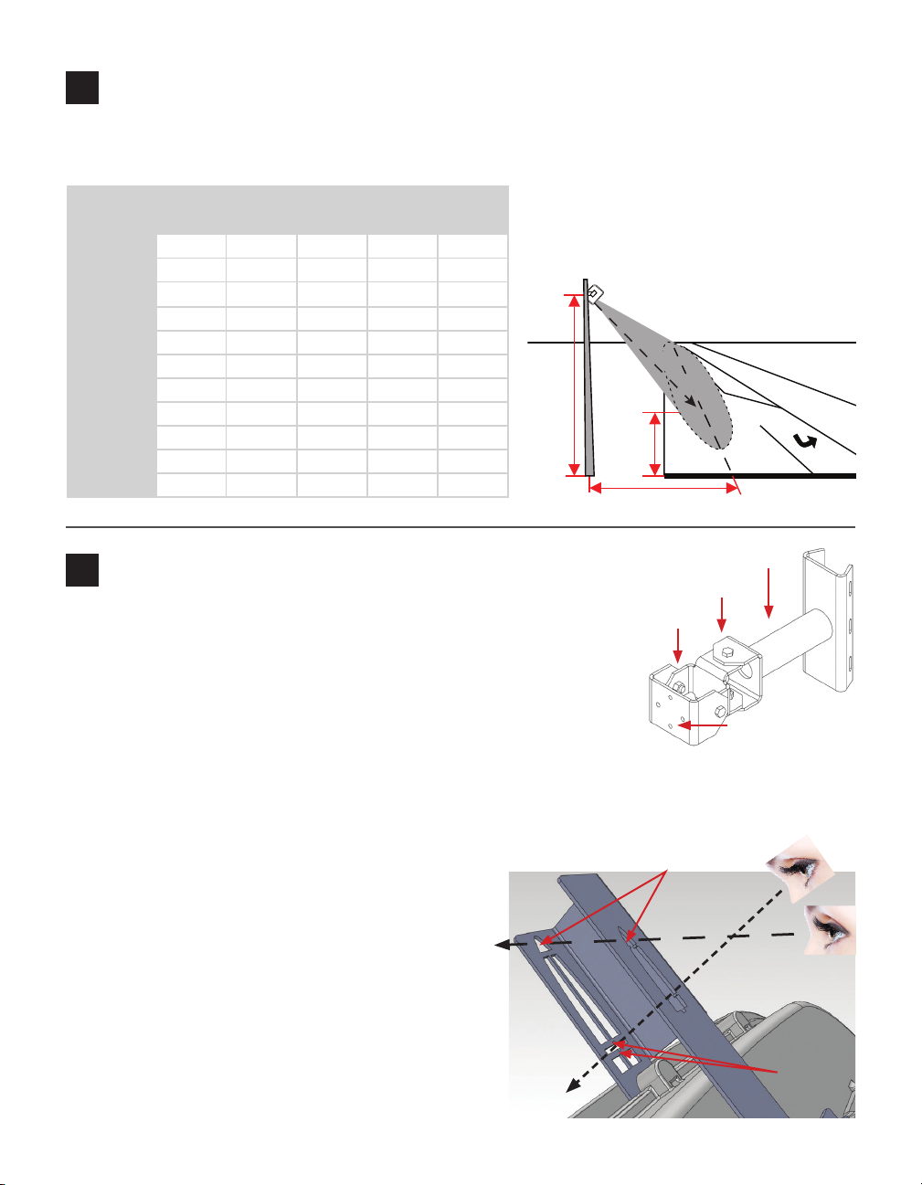
1 Pan and tilt the mount (using swivel joints 1 and 2) so that the mount head
2 Strap the mount to the pole with the
mount’s main sha pointed in the general
direction of the target. Target location is
determined by target distance table.
Line-of-sight to target
Height
X
Target
Distance
Oset (perpendicular)
Main Shaft
1
2
points to the target location in the center of the lanes of interest.
2 Attach the sensor to the mount making sure the sensor can still roll with
respect to the mount head.
3 Attach the viewnder by centering the arched notch over the top-middle of
the sensor and inserting it into position.
Mount Head
4 With your eyes about one foot from the viewnder (viewpoint 1), use the
visual cue tabs to look directly through the target crossbars. Tilt the sensor until the target location
lines up between the target crossbars.
5 Pan the sensor until the target location is centered between the
notches in the target crossbar. When you have the correct view
Framed archways
angle, the bottom center notch should also line
up with the bottom part of the long,
narrow alignment bar.
Note. For a better view, close one eye and
Line-of-sight to
upstream
detection area
move closer to the viewnder. If there is
not enough headroom, you can use a digital
camera directly behind the viewnder.
1
2
e framed archways (viewpoint 2) will be used in
the next step to verify the upstream detection area.
Line-of-sight
to target
Target
crossbars
Page 3

Align sensor to roadway
5
1 Roll the sensor until the long, narrow bar is
parallel with the center of the lanes of interest on the roadway. Vehicle paths should be
parallel to the long, narrow bar.
2 To verify your alignment within the upstream detection area, move
your head down so you can see the top crossbar and the archway, then
make sure the archways overlap and the top tabs line up with the top
crossbar. Vehicle paths should still be parallel to the long, narrow bar.
3 Tighten down the pan and tilt bolts, then tighten down the four
bolts on the backplate.
Attach the SmartSensor 6-conductor cable and ground the sensor
6
1 Squeeze about 25% of the silicon dielectric compound into the connector
at the base of the sensor. Wipe o any excess compound.
2 Insert the cable into the connector and twist clockwise until it clicks into place.
3 To avoid movement, strap the cable to the pole or run it through a con-
duit, leaving a little slack at the top of the cable to reduce strain.
e cable should run straight to the main trac cabinet. In areas with an
abundant amount of electrical surges, it is recommended that you use a polemount box with surge protection at the base of the pole. It is necessary, however, to ground the sensor:
1 Connect a grounding wire to the grounding lug on the bottom of the sensor.
2 Connect the other end of the grounding wire to the earth ground for the pole that the sensor is mount-
ed on. Do not attempt to run the grounding wire back to the main trac cabinet.
3 In the main trac cabinet use a volt meter to verify no electrical potential dierence between sensor ground
and cabinet ground. Volt meter probes between the 6-conductor black GND/DC- wire and cabinet ground.
Align long, narrow bar
with middle of lanes
of interest
Sensor roll
Mount the backplate in the main trac cabinet and wire power
7
Once installation of the sensor is complete, the intersection preassembled
backplate must be installed in the main trac cabinet. To do so, locate the area
planned for mounting the backplate—usually on the side panel of a NEMA-style
cabinet. en attach the backplate with the U-channel mounting screws.
Connect power to the AC terminal block on the bottom DIN rail:
1 Connect a line wire (black) to the bottom of the “L” terminal block.
2 Connect a neutral wire (white) to the bottom of the “N” terminal block.
3 Connect a ground wire (green) to the bottom of the “G” terminal block.
Continued on next page
Page 4

4 Turn on AC mains power.
5 Press the circuit breaker switch on the le side of the top DIN rail to switch power to the backplate.
6 Verify power is regulated by verifying that the DC OK LEDs are illuminated on the Click 201/202/204.
Terminate the SmartSensor 6-conductor cable
8
To land the 6-conductor cable into the terminal block section:
1 Aer routing your SmartSensor 6-conductor cable into the cabinet, strip
back the cable jacket and shielding on the service end of the cable.
2 Open the insulation displacement connectors on the plug by inserting a
small screwdriver into each square slot and rocking it back.
3 Insert the wire leads into the bottom side of the plug-in terminal accord-
ing to the colors of the wires and the labels on the plug. Make sure the
wires are completely inserted in the terminal.
4 Close the insulation displacement connector by reinserting the screwdriver into the square slot and
rocking it forward. e plug-in terminals will automatically complete the electrical connection. ere is
no need to manually strip the insulation on the end of each wire.
5 If you removed the plug to wire it, insert it back into the terminal block section.
Complete wiring
9
e Click 222 has three RJ-11 jacks on the faceplate:
˽ RS-485 A (yellow) – Connects the data bus from sensor 1 to the rack cards.
˽ RS-485 B (orange) – Connects the data bus from sensor 2 to the rack cards.
˽ RS-485 Bridge (blue) – Connects the conguration buses from sensors 1 and 2 to the
control bridge, to the detector rack cards, and to the T-bus. is jack combines the
input from ports C and D.
To connect and autobaud to the detector rack cards:
1 Connect from the Click 222 RS-485 A port to a bus 1 port on the appropriate rack
card. Connect from the Click 222 RS-485 B port to a bus 1 port on another rack card.
2 If you are using Click 112 cards, use a patch cord to share bus 1 between cards dedicated to the
same sensor. If you have more than two sensors in your system, repeat steps 1–3 to connect
bus 1 for all remaining rack cards.
3 Connect from a Click 222 bridge port to bus 2 of the rack cards.
4 Daisy-chain between the bus 2 ports of all of the rack cards for device conguration.
5 e Click 112/114 should begin to receive data from the sensor.
© 2014 Wavetronix LLC. All rights reserved. Protected by US Pat. Nos. 6,556,916; 6,693,557; 7,426,450; 7,427,930; 7,573,400; 7,889,097; 7,889,098; 7,924,170; 7,991,542; 8,248,272;
8,665,113; and Cdn. Pat. Nos. 2,461,411; 2,434,756; 2,512,689; and Euro. Pat. Nos. 1435036; 1438702; 1611458. Other US and international patents pending. Wavetronix, SmartSensor, Click,
Command and all associated logos are trademarks of Wavetronix LLC. All other product or brand names as they appear are trademarks or registered trademarks of their respective holders. Product specifications are subject to change without notice. This material is provided for informational purposes only; Wavetronix assumes no liability related to its use.
WX-500-0168
 Loading...