

Page 1
Wavetronix LLC
TM
SmartSensor HD
User’s Manual
www.SmartSensor.us
TM
SS 125
Version 1.0
January 13, 2006
5314 N. 250 W., Suite 110, Provo, UT 84604, USA (801) 764-0277
Page 2

TMTM
Wavetronix LLC
Wavetronix Contact Information.................................................................................................... 2
Copyright / Trademarks.................................................................................................................. 2
Product Notifications...................................................................................................................... 3
Introduction..................................................................................................................................... 5
Unpacking....................................................................................................................................... 6
Installing the SmartSensor.............................................................................................................. 7
Step 1 – Assemble the Mounting Bracket................................................................................... 7
Step 2 – Attach the SmartSensor to the Mounting Bracket........................................................ 7
Step 3 - Mount SmartSensor on a Pole....................................................................................... 8
Step 4 – Connect SmartSensor Cable ......................................................................................... 8
Step 4 – Connect SmartSensor Cable ......................................................................................... 9
Step 5 – Configure the SmartSensor.........................................................................................10
Step 5.1 - Installing the SmartSensor Manager Software..................................................... 10
Step 5.2 - Connecting Your Computer to the SmartSensor.................................................. 11
Serial Cable – there are two serial options available for connecting to the SmartSensor: ....... 11
Serial Connection.............................................................................................................. 12
Modem Connection.................................................................Error! Bookmark not defined.
Internet Connection........................................................................................................... 13
Additional Features of the SmartSensor Manager....................................................................16
Manual Configuration.......................................................................................................16
Saving the Configuration.................................................................................................. 16
Undoing Manual Changes................................................................................................. 16
Restarting LaneSmart........................................................................................................ 16
Using Data Viewing and Logging Tools.............................................................................. 16
Event Data......................................................................................................................... 16
Time-Interval Data............................................................................................................ 16
Using the SmartSensor Manager Menu................................................................................ 16
Connection........................................................................................................................ 16
LaneSmart......................................................................................................................... 16
TrafficView.......................................................................................................................16
Data Logs.......................................................................................................................... 17
Firmware Upload.............................................................................................................. 17
Appendix....................................................................................................................................... 17
RS-232 Communication Port..................................................................................................... 18
RS-485 Communication Port..................................................................................................... 18
1
Page 3

TMTM
Wavetronix LLC
Wavetronix Contact Information
380 S. Technology Ct.
Lindon, Utah 840424 USA
Voice: (801) 764-0277
Fax: (801) 764-0208
Web: www.smartsensor.us
E-mail: sales@smartsensor.us
Or
support@smartsensor.us
Copyright / Trademarks
© Copyright 2002 Wavetronix LLC, All rights reserved.
SmartSensor, the SmartSensor logo and LaneSmart are trademarks of Wavetronix LLC. SeaLINK
is a trademark of Sealevel Systems Inc. All other product or brand names as they appear are
trademarks or registered trademarks of their respective holders.
The Company shall not be liable for any errors contained herein or for any damages arising out of
or related to this document or the information contained therein, even if the Company has been
advised of the possibility of such damages.
This document is intended for informational and instructional purposes only. The Company
reserves the right to make changes in the specifications and other information contained in this
document without prior notification.
2
Page 4
TMTM
Product Notifications
FCC Part 15 Compliance
Wavetronix LLC
Risk of Electrical Shock
This equipment complies with Part 15 of the FCC (Federal Communications
Commission) rules. Any changes or modifications not expressly approved by
the manufacturer could void the user’s authority to operate the equipment.
Note: This equipment has been tested and found to comply with the limits
for a Class A digital device, pursuant to part 15 of the FCC Rules. These
limits are designed to provide reasonable protection against harmful
interference when the equipment is operated in a commercial
environment. This equipment generates, uses, and can radiate radio
frequency energy and, if not installed and used in accordance with the
instruction manual, may cause harmful interference to radio
communications. Operation of this equipment in a residential area is likely
to cause harmful interference in which case the user will be required to
correct the interference at his own expense.
An authorized electrical technician should perform installation and operation of
this unit. Persons other than authorized and approved electrical technicians
should NOT attempt to connect this unit to a power supply and/or traffic control
cabinet, as there is a serious risk of electrical shock through unsafe handling of
the power source. Extreme caution should be used when connecting this unit to
an active power supply.
Technical Service
Do not attempt to service or repair this unit. This unit does not contain any
components and/or parts serviceable in the field. Any attempt to open this unit,
except as expressly written and directed by Wavetronix will void the customer
Warranty. Any visible damage to exterior seal labels will void the Warranty.
Wavetronix is not liable for any bodily harm or damage caused if unqualified
persons attempt service or open the back cover of this unit. Refer all service
questions to Wavetronix or an authorized distributor.
Installation Safety Precaution
Caution should be used when installing any sensor on or around active
roadways. Serious injury can result when installation is performed using
methods that are not in accordance with authorized local safety policy and
procedures. Always maintain an appropriate awareness of the traffic conditions
3
Page 5
TMTM
and safety procedures as they relate to specific locations and installations.
Symbol Legend
The lightning bolt within an equilateral triangle symbol is intended to alert the user to
the risk of electric shock.
The exclamation point within an equilateral triangle is intended to alert the user to the
presence of important installation, operating, and maintenance instructions.
Wavetronix LLC
4
Page 6

TMTM
Introduction
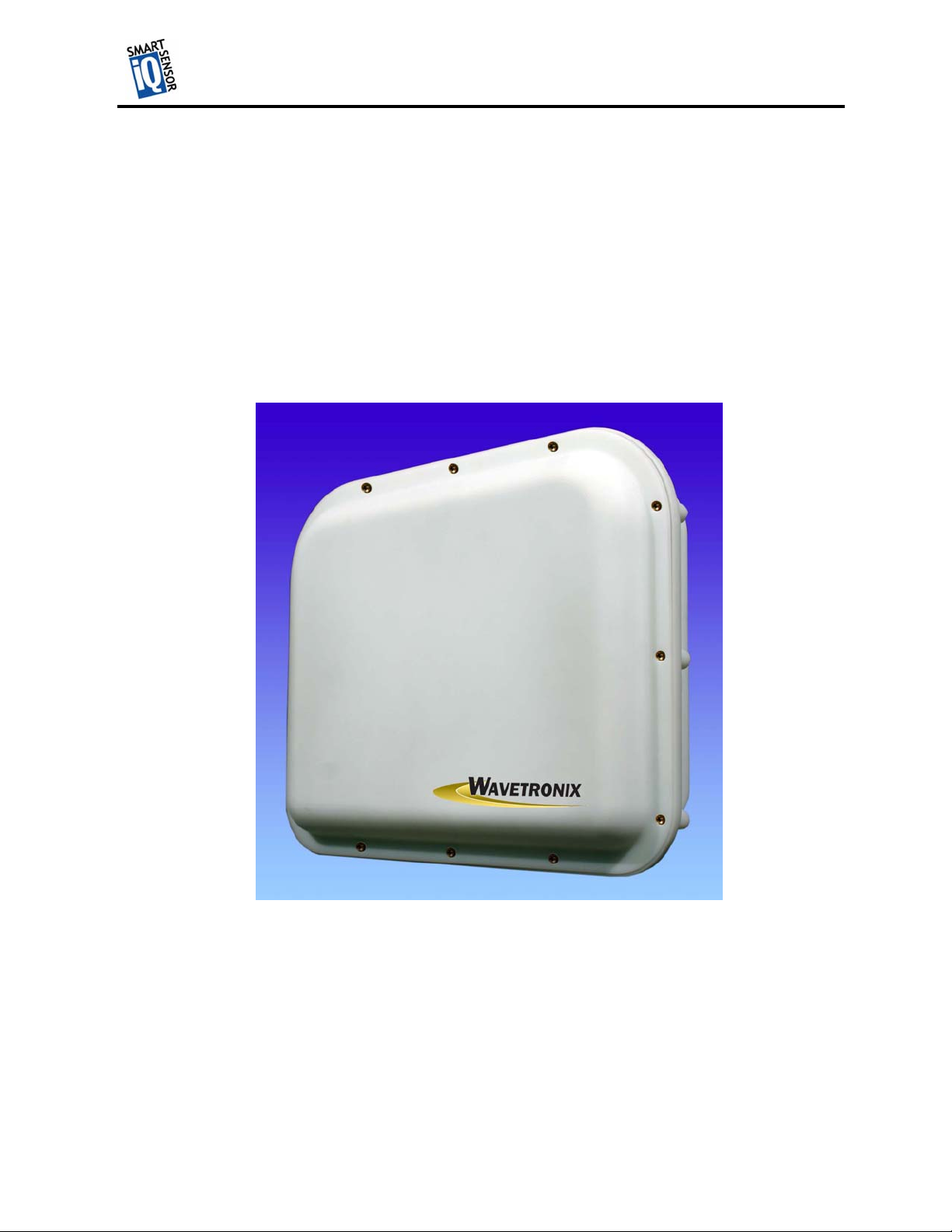
The Wavetronix SmartSensor HD traffic sensor utilizes the latest technology to collect and
deliver traffic statistics. Capable of measuring traffic volume, average speed, individual vehicle
speed, lane occupancy and presence, the SmartSensor HD collects information through the use of
a 24.125 GHz (K band) operating radio frequency. Classified as Frequency Modulated
Continuous Wave (FMCW) radar, the SmartSensor HD detects and reports traffic conditions
simultaneously over as many as ten lanes of traffic. Once SmartSensor HD is installed, the
configuration process is quick and easy. After installation, this unit will require little or no onsite maintenance, and can be remotely reconfigured for optimal performance. The following
pages detail the easy step-by-step process of getting started with the SmartSensor HD.
Wavetronix LLC
5
Page 7

TMTM
Unpacking
A typical sensor packages contains the following items:
• SmartSensor HD SS-125 detector
• Stainless steel mounting plate
• Mounting fasteners
• Sensor mount bracket
• Sensor cable
• User’s Manual
• CD and/or diskette with software
If any of these items are missing, note the serial number located on the side of the sensor and
contact the Wavetronix support. Additional products may be purchased through your distributor;
software and firmware may be obtained through Wavetronix sales.
Wavetronix LLC
6
Page 8

TMTM
Installing the SmartSensor
The installation of the SmartSensor HD is a process that involves five simple steps:
(1) Assemble the mounting bracket.
Wavetronix LLC
(2) Attach the SmartSensor HD to the mounting bracket.
(3) Mount the SmartSensor HD to a pole.
(4) Connect SmartSensor cable.
(5) Configure the SmartSensor HD.
Each step is described in detail in this section.
Step 1 – Assemble the Mounting Bracket
Secure stainless steel mounting plate (item 1) to sensor mount bracket (item 2) with enclosed
tapered mounting fasteners (item 3) as shown in Figure 1.
Figure 1 Bracket Assembly
Step 2 – Attach the SmartSensor HD to the Mounting Bracket
Take assembled sensor mount bracket from step 1 and align stainless steel mounting plate to the
threaded holes on the back of the SmartSensor. Using the remaining fasteners, attach the
assembled bracket mount to the SmartSensor. (Figure 2) Tighten until firm. DO NOT
OVERTIGHTEN FASTENERS
.
Figure 2 Sensor Attachment
7
Page 9
TMTM
t
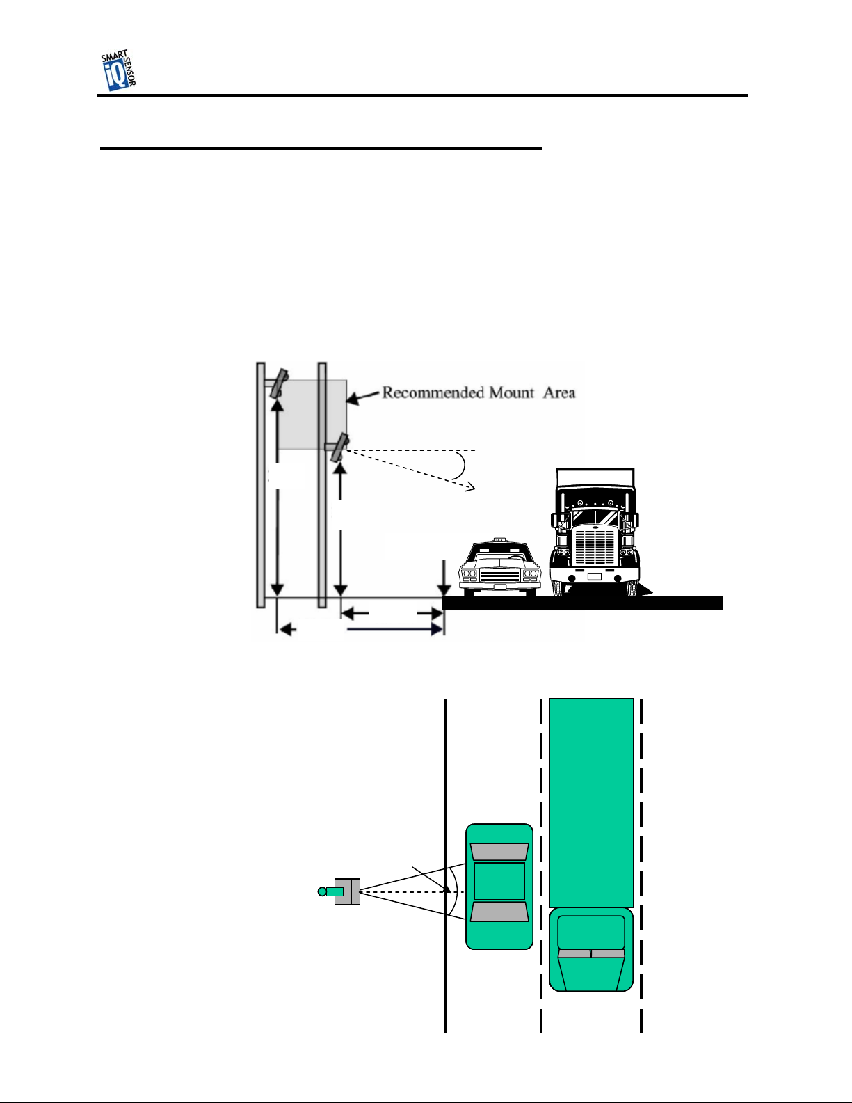
Step 3 - Mount SmartSensor HD on a Pole
Firmly secure the SmartSensor to a pole or fixed location at a height between 4 and 10 m from
the desired monitoring surface. Firmly secure the mounting bracket on a vertical or horizontal
pole using the ½ inch band straps included in shipment. The bracket is adjustable and has 70° of
tilt adjustability. Aim the front of sensor at the center of the detection area. If the SmartSensor is
installed closer than 5 m to the first lane of traffic, point the sensor up (smaller tilt angle) and
choose a lower mounting position as shown in table 3.1. Adjust the side-to-side angle to within
2° of perpendicular to the flow of traffic. Connect the power/communication cable to the
SmartSensor and attach the modem antenna if applicable. Attention should be given to securing
the loose cable to the pole with minimum slack, to avoid undue movement from wind.
Wavetronix LLC
10 m
15 m
4 m
s
1
Point of
Interest
3 m
Figure 3 Installation Diagram
Side-to-Side
Angle
Tilt angle
8
Figure 4
Page 10

TMTM
Step 4 – Connect SmartSensor Cable
The sensor connector as shown in Figure 5 a. is keyed such that it can only fit one way. Attach it
to the coupling at the base of the sensor. The cable should be strapped to the pole or run through
conduit to reduce the strain on the cable.
Figure 5
Wavetronix LLC
a. Sensor Connector b. Service End
The service end of the cable (Figure 5 b.) has a +DC and GND for a power supply of 12 to 24
VDC. Up to three communication ports (either RS-232 or RS-485) are available to connect the
SmartSensor to a modem or other communication device. Typically one RS-485 port is available
plus one or two RS-232 ports. Figure 5 shows 2 communication ports. Refer to the appendix for
pin assignments.
9
Page 11
TMTM
Step 5 – Configure the SmartSensor HD
Wavetronix LLC
To confirm the configuration of lanes (detection zones) on the SmartSensor HD connect to the
SmartSensor HD through a serial, Internet, or modem connection. To do this you must first
install the SmartSensor Manager CE on a pocket PC or laptop; second, connect the SmartSensor
HD to your pocket PC or laptop; third, use the Lane Configuration utility under Lane Setup in
SmartSensor Manager CE to confirm and save the configuration of lanes in the sensor.
Step 5.1 - Installing the SmartSensor Manager Software
SmartSensor Manager CE 1.0 is the software that enables users to configure and interact with the
unit. This software is contained on the compact disc that is shipped with each sensor. Before
installing SmartSensor Manager CE 1.0 you must install the .Net framework which is included in
the setup CD. To install SmartSensor Manager CE, place the CD in the CDR drive and double
click the icon labeled Setup.exe listed in the contents of the CD. This executes the setup program
that will copy all the necessary files to the hard drive and create icons for the start menu and
desktop on the PC or laptop.
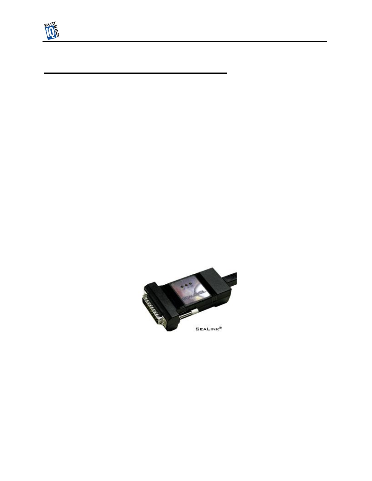
Step 5.1.1 Installing the SeaLink
(IMPORTANT NOTE: it is only necessary to install the SeaLink drivers if you are going to use
the SeaLink USB/RS-485 adapter (see Figure 6) to connect to the SmartSensor HD)
TM
Serial Communication Drivers (Optional)
Figure 6
Once the InstallShield setup program has finished installing the SmartSensor HD Manager
software it may be necessary to install the SeaLink serial communication drivers so that you can
connect to the sensor using the USB/RS-485 serial cable. To do this simply click on the Start
icon, choose Programs, SmartSensor HD Manager v1.0, then click on the SeaLink setup.exe icon
that was placed there for you when the SmartSensor HD manager Software was installed. This
will run another InstallShield wizard, which will guide you through the install process. When this
wizard is finished reboot your computer. However, before rebooting, connect the USB to RS-485
serial cable to a USB port on your computer as described below.
10
Page 12

TMTM
Step 5.2 - Connecting Your Computer to the SmartSensor HD
There are several ways to connect your computer to the SmartSensor HD as listed below.
Step 5.2.1 – Physically Connecting the SmartSensor HD to your Computer
Serial Cable – there are two serial options available for connecting to the SmartSensor HD:
1. RS-232 using a 9-pin null modem serial cable connected to the standard RS-232 serial port on
your PC. This configuration is shown in Figure 7 below.
Wavetronix LLC
Null Modem
cable
12 Volts DC
Figure 7
2. Universal Serial Bus (USB) to RS-485 using a SeaLink adapter shown in Figure 8, that plugs
directly into the 25-pin connector on the Sensor cable.
SeaLink adapter
USB cable
12 Volts DC
Figure 8
Analog Modem – the SmartSensor HD can be connected directly to an external analog modem
through which your PC’s modem can then dial-up to establish a connection. For example, this
9-pin connector
labeled RS-232A
Smart Sensor
cable
25-pin connector
labeled RS-485
Smart Sensor
cable
11
Page 13

TMTM
Wavetronix LLC
could be a regular POTS analog modem or a wireless modem (GSM, etc.) if service is available in
your area.
Internet – the SmartSensor HD can be connected to the Internet allowing access to the sensor
from anywhere with Internet access. There are two ways to connect the Smart Sensor to the
Internet:
1. CDMA modem – Code Division Multiple Access (CDMA) is a wireless Internet service
available in most metropolitan areas in the United States and coverage continues to expand.
The SmartSensor HD can be equipped with an optional external CDMA modem and assigned
an Internet address.
2. Ethernet to serial converter – the SmartSensor HD can be connected to a local area network
(LAN) by using an Ethernet-to-serial adapter. As an option, the SmartSensor HD can be
shipped with a Click! 301 serial to Ethernet adapter that is Internet addressable making it
possible to connect to the sensor from anywhere the adapter’s address is accessible.
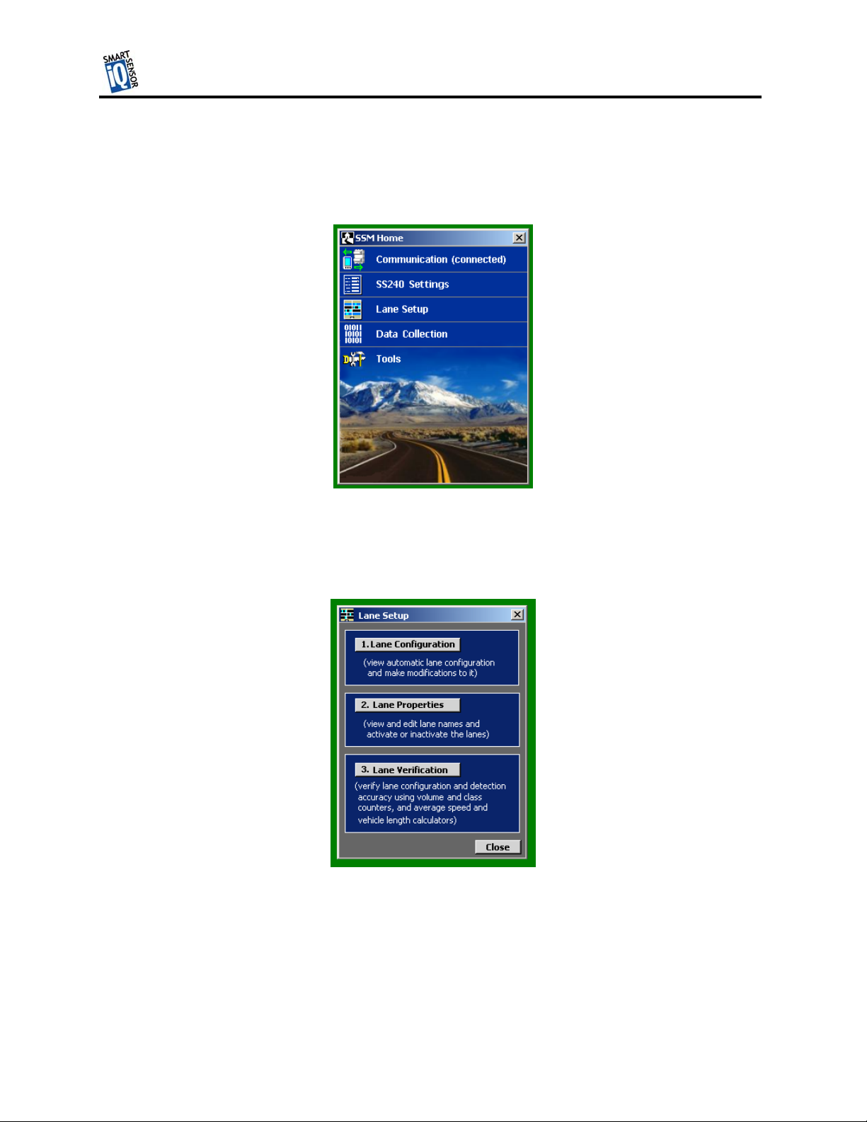
Step 5.2.2 - Establishing a Connection Using SmartSensor Manager CE 1.0
Once your computer is physically connected to the SmartSensor HD by one of the methods
described above, use SmartSensor Manager CE to visually configure and interact with it. To
begin, either click on the icon that was placed on your desktop screen or click the icon found on
the start menu. The Homepage screen should appear as shown below:
Figure 9
Serial Connection
Click on the icon next to “Communication” to bring up the communication screen as shown in
Figure 10. Set the connection to Serial and the Port and Baud rate to the appropriate settings. If
you do not know the baud rate, set the baud to auto-baud. Set the appropriate Subnet and ID if
you know the sensor ID. If you do not know the sensor ID, set it to its maximum value of 65535.
12
Page 14

TMTM
Wavetronix LLC
This can easily be done by highlighting the most significant digit (10,000) and scrolling it up past
60,000. Next click connect and you should be connected.
Figure 10
Internet Connection
If you chose “Internet” under Connection, in the communication dialog window (Figure 10) you
must then enter the Internet address (IP address & TCP port number) of the sensor of interest. The
first box is used for the IP address, which consists of four numbers ranging from 0-255 separated by
dots (‘.’). Enter the IP address assigned to either the CDMA modem or the Click! 301 Ethernet-toSerial adapter. The second box expects an integer value in the range of 0-65536, which is the port
number also assigned to the CDMA modem or the Ethernet-to-Serial adapter.
Once an IP address and port number are input, set the subnet and sensor ID to the correct values or
their maximum values (255 and 65535) to search for the correct values. You can then press the
Connect button to connect to the sensor.
When the connection is completed, the message “Remote connection established!” is displayed and
“Disconnect” and “Continue” buttons appear. Pressing “Continue” takes you to a screen that
displays a view of the current sensor configuration. Connection failure can occur for various
reasons, if failure occurs repeatedly call Wavetronix for assistance.
13
Page 15
TMTM
Wavetronix LLC
Step 5.2.3 - Using SmartSensor Manager CE’s Lane Configuration Utility
After a connection is made to the SmartSensor the home page as shown in Figure 11 appears. To
configure lanes click on Lane Setup.
Figure 11
The lane setup options window then appears as shown in Figure 12. To start the lane configuration
process the Lane Configuration button.
Figure 12
14
Page 16
TMTM
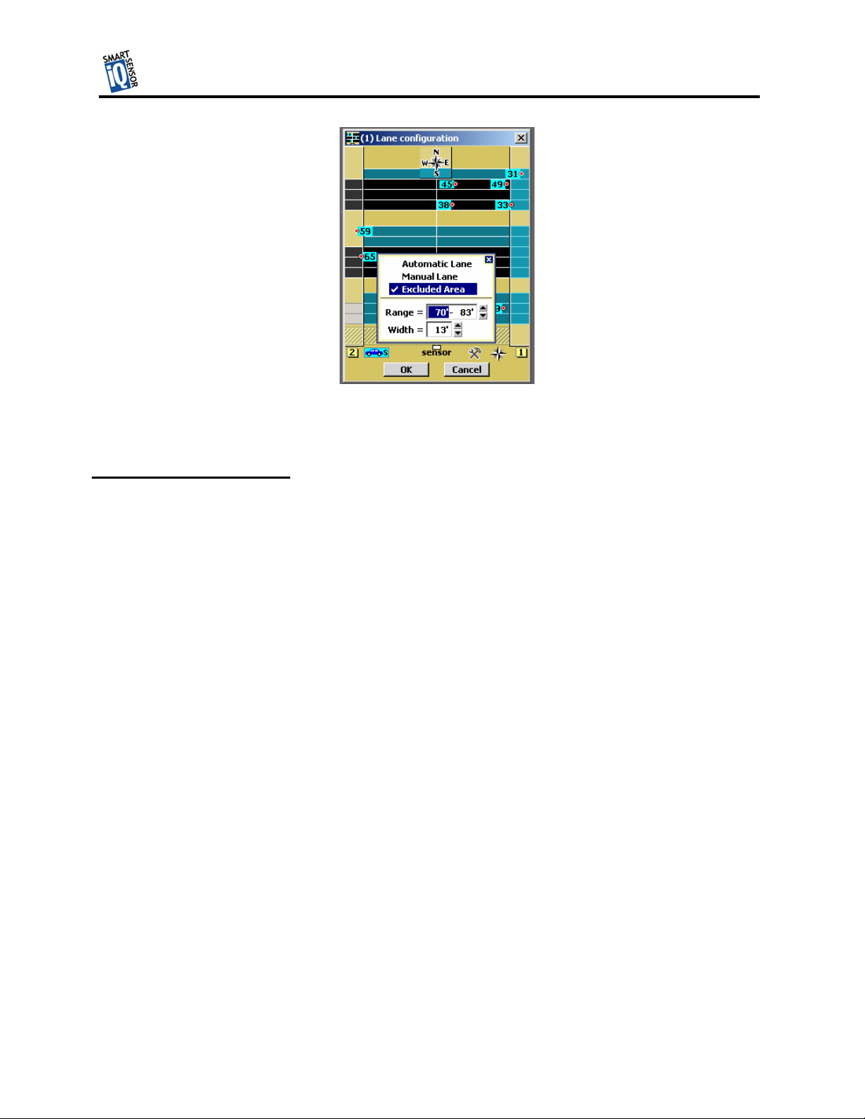
Figure 13
Automatic Configuration
That completes the normal installation and configuration process. The remainder of this document
explains some of the added features of the SmartSensor Manager software and how it allows you to
manually configure lanes, monitor and record traffic data and upgrade your SmartSensor HD
Wavetronix LLC
15
Page 17

TMTM
Additional Features of SmartSensor Manager CE
The SmartSensor Manager is designed to quickly confirm or adjust the configuration of the
SmartSensor, tools to verify the performance of the SmartSensor and upgrade the SmartSensor.
Manual Configuration
The newly activated buttons remain pressed when you click them to enable the drawing function of
the button you press. To change the configuration, click the appropriate button and move your
cursor over the window showing roads and vehicles. Then make the changes.
Figure 14
Saving the Configuration
Undoing Manual Changes
Restarting LaneSmart
Wavetronix LLC
Using Data Viewing and Logging Tools
Event Data
Time-Interval Data
Using the SmartSensor Manager Menu
Connection
LaneSmart
TrafficView
16
Page 18

TMTM
Data Logs
Firmware Upload
Appendix
SmartSensor Specifications
Operating Frequency: 24.125 GHz (K-band)
Detection Zones: Up to 10 traffic lanes simultaneously
Detection Range: 250 ft
Measured Quantities: Speed, occupancy, volume, presence, classification
Communications: RS-485 or RS-232 connection
Power: 8 watts @ 9-30 VDC
Weight: 5 lbs.
Physical Dimensions: 27 cm. H x 33.5 cm W x 8.3 cm D
Zone Resolution: 3 m
Ambient Operating Temp: -40C to +70C
Humidity: Up to 95% RH
Shock: 10 g 10ms half sine wave
Transmitted Power at 3m: <100dBuV/m @ 24.125Ghz
Wavetronix LLC
17
Page 19

TMTM
Cable Connector Definitions
RS-232 Communication Port
The RS-232 Communication Port is configured in a 9-pin “D” male connector with the following
pin out:
RS-232 Pin Out
1: N/C 6. N/C
2: Data from Modem 7. N/C
3: Data to Modem 8. N/C
4: N/C 9. N/C
5: GND
RS-485 Communication Port
The RS-485 Communication Port is configured in a 25-pin “D” female connector that with the
following pin out:
RS-485 Pin Out
Wavetronix LLC
1: N/C 10: N/C 18: N/C
2: -RS-485 11: N/C 19: N/C
3: -RS-485 12: N/C 20: N/C
4: N/C 13: N/C 21: N/C
5: N/C 14: +RS-485 22: N/C
6: N/C 15: N/C 23: N/C
7: GND 16: +RS-485 24: N/C
8: N/C 17: N/C 25: N/C
9: N/C
18
 Loading...