

Page 1

SmartSensor 105
INSTALLER QUICK-REFERENCE GUIDE
Complete steps 1–9 to integrate the Wavetronix SmartSensor into your trac application. If
you need technical support or have questions, please contact Wavetronix Technical Services at
801.734.7200. For more information, see the SmartSensor User Guide.
Identify the components in your system package
1
e components below are common for a SmartSensor 105 installation; the contents of your package may
be dierent.
Mount Bracket Sensor Sensor
Select the mounting height
2
1 Determine the oset by
measuring the distance
from the nearest detection lane to the pole the
sensor is mounted on.
2 Find the recommended
mounting height by using this table.
e range of ideal osets is
highlighted in gray.
www.wavetronix.com
801.734.7200
Cable
Oset from first
detection lane
(ft/m)
10/3 12/3.7 9/2.7 15/4.6
15/4.6 15/4.6 12/3.7 18/5.5
20/6.1 18/5.5 15/4.6 20/6.1
25/ 7. 7 20/6.1 17/5.2 25/ 7.7
30/9.1 22/6.7 19/5.8 30/9.1
35/10.7 23/ 7. 0 20/ 6.1 35/10.7
40/12.2 25/ 7. 7 22/6.7 40/12.2
45/13.7 27/8.2 23/ 7. 0 45/13.7
50/15.2 30/9.1 25/7. 7 must be < oset
Recommended
mounting height
(ft/m)
Pole
Cabinet
Minimum
mounting height
(ft/m)
Homerun
Cable
Maximum
mounting height
(ft/m)
Page 2
1234567
8
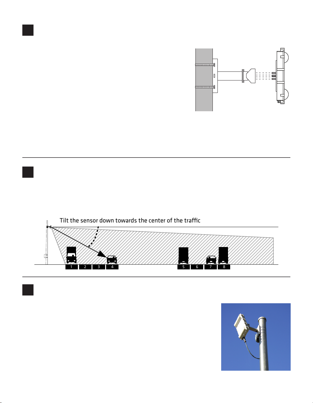
Tilt the sensor down towards the center of the trac
Attach the sensor and mount bracket to the pole
3
Attach the mount bracket to the pole:
1 Insert the stainless steel straps through the slots in the mount
bracket.
2 Position the mount on the pole so that the head of the mount
is pointing towards the middle of the lanes of interest.
3 Tighten the strap screws.
Attach the sensor to the mount bracket:
1 Align the bolts on the back of the SmartSensor with the
holes on the mounting bracket. e large 25-pin connector on
the SmartSensor should be pointing towards the ground.
2 Place the lock washers onto the bolts after the bolts are in the mounting bracket holes.
3 read on the nuts and tighten.
Align the sensor to the roadway
4
1 Tilt the sensor down so that the front is aimed at the center of the detection area.
2 Adjust the side-to-side angle to within approximately 2° of perpendicular to the ow of trac.
3 Tighten the mounting bracket bolts.
Attach the 9-conductor cable
5
1 Tear the tab o the tube of silicon dielectric compound and squeeze
about 25% of the silicon into the connector at the base of the SmartSensor. Wipe o any excess compound.
2 Insert the cable into the connector and twist clockwise until you hear it
click into place.
3 To avoid undue movement from wind, strap the cable to the pole or run
it through a conduit, but leave a small amount of slack at the top of the
cable to reduce strain.
Page 3

Attach the pole-mount box
+DC
GND
GND
GND
RTS
CTS
TD
RD
-485
+485
GND
GND
6
1 Attach the mounting brackets to the back of the pole-mount
box.
2 read the mounting straps throught the mounting brackets.
3 Position the pole-mount box onto the pole and attach the box to
the pole using the mounting straps.
4 Run the sensor and homerun cables through the cable grips on
the bottom of the pole-mount box.
Connect surge protection and power
7
1 Disconnect the Click! 200 from the
DIN rail.
2 Disconnect the green screw terminals
on the PROTECTED side (top) of
the Click! 200 and wire the sensor
cable as shown in the diagram.
3 Connect the Click! 200 to the DIN
rail.
4 Connect the ground terminal to the
DIN rail and the earth ground wire
to the lug bolt on the bottom of the
pole-mount box.
5 Connect the exterior lug bolt to earth
ground.
6 Connect 10–30 VDC to the +DC
and –DC terminals on the UNPROTECTED side (bottom) of the Click!
200.
Note. If you have a homerun connection to
a main trac cabinet, refer to Chapter 2 of
the SmartSensor User Guide.
From
From
Sensor
SmartSensor
Power Drain
Black
Red
RS-485 Drain
White
Blue
Gray
RS-232 Drain
Violet
Yellow
Brown
Orange
Page 4

Install the SmartSensor Manager (SSM) software
8
1 Find the setup program from the Wavetronix website by going to www.wavetronix.com, clicking on the
Support tab, choosing the SmartSensor product line, and choosing SmartSensor 105 from the drop-
down menu.
2 To install, simply download the le to your local machine.
3 Double-click on the SSM icon to open SmartSensor Manager.
Make a connection
9
1 Attach a serial cable to the RS-232 or RS-485 port of a surge protection module.
2 Once SmartSensor Manager is open, select the type of connection you want to make (Serial, Modem
or Internet).
3 Click OK.
After you are connected, the Lane Conguration page will appear, allowing you to automatically congure
the SmartSensor 105.
© 2012 Wavetronix LLC. All rights reserved. Protected by U.S. Patent Nos. 6,556,916; 6,693,557; 7,426,450; 7,427,930; 7,573,400; 7,889,097; 7,889,098; 7,924,170; 7,991,542 Cdn.
Pat. Nos. 2461411; 2434756 and Euro. Pat. Nos. 1435036; 1438702; 1611458. Other U.S. and international patents pending. Wavetronix, SmartSensor, Click, Command and all associated logos are trademarks of Wavetronix LLC. All other product or brand names as they appear are trademarks or registered trademarks of their respective holders. Product
specifications are subject to change without notice. This material is provided for informational purposes only; Wavetronix assumes no liability related to its use.
WX-500-0166
 Loading...