

Page 1
Click 511 Digital I/O Repeater
INSTALLER QUICK-REFERENCE GUIDE
Select mounting locations
1
In a Click 511 application, there will be between two and nine devices:
˽ Server – One device will act as a server. is server, located at a base station, will poll the client devices
about the state of their connected digital inputs.
˽ Client – One or more devices (up to eight) will act as clients. ese clients, located close to the digital
output devices being monitored, will report the status of their digital inputs.
How to use on-device configuration features
2
is document covers how to set up the client devices, and then how
to set up the server. To do so, you rst need to know the basics of the
device’s conguration features.
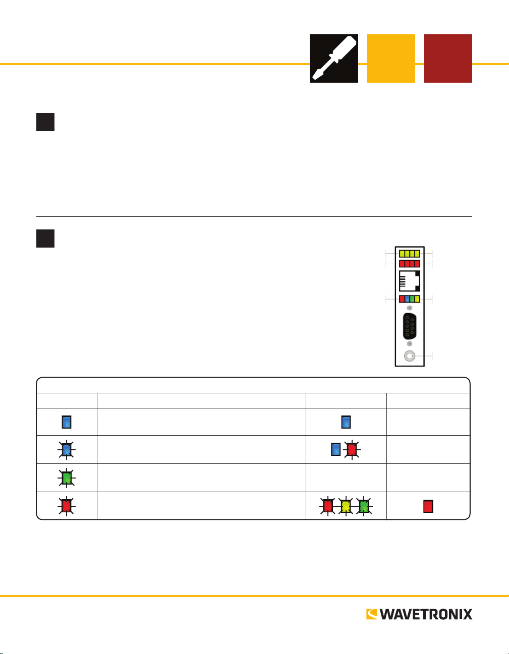
e Click 511 has four LEDs that monitor device activity and help
you select tasks and operating modes. It also has two banks of LEDs:
one of yellow LEDs that represent submenu 1 and one of red for submenu 2. It also has a push-button, labeled Mode Switch, also used for
selecting tasks and operating modes.
Yellow LEDs
Red LEDs
Multicolored LEDs
Sub Menu 1
Sub Menu 2
Main Menu
Button
LED task-indicating functions:
Client – Sets the device as a client (attached to the
digital output device being monitored)
Server – Sets the device as a server (used as a base
station)
Server Output Setup – Lets you you specify the output
type for server operation
Reset – Release push-button when red LED is blinking
to reset to factory defaults.
Note. How to select and use Client, Server, and Server Output Setup modes will be covered later in this
document. e Reset task can be used at any time to reset the device to factory defaults. If reset, the Click
511 will default to being a client with ID number 1.
www.wavetronix.com
801.734.7200
– –
Continued on next page
–
–
Page 2
Select a task or operation function by navigating through the main menu (multicolored LEDs) and the submenus (yellow and red LEDs) using the push-button as described below:
1 Enter the m 1 ain menu and cycle through it by
holding the push-button down.
2 Release the push-button once the cycle reaches
the desired function.
3 Press the push-button again to select the func-
tion. Once selected, the function will either
start running or the rst submenu (yellow
LEDs) will start.
4 Hold the push-button to cycle through the rst
submenu.
5 Release the push-button once the desired sub-
Mount and wire power to the client devices
3
Select a mounting location for each client (you can have between 1 and 8) in
a cabinet or other installation near the digital output device to be monitored.
e Click 511 mounts over a T-bus for power and communication. Do the
following for each device being used in your installation:
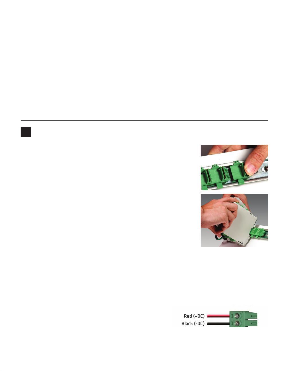
1 If the Click 511 was shipped with the T-bus connector attached, remove
the connector from the module.
2 Snap the connector onto the DIN rail by positioning it over the rail
with the male connector pointing to the right. Hook one arm over the
edge of the DIN rail and press down on the other arm until it snaps into
place.
3 Connect the T-bus connector to the rest of the T-bus by sliding them
together until you hear them snap into place.
4 Mount the Click 511 onto the DIN rail: position it properly over the T-
bus connector, hook the lip over the lower edge of the DIN rail, and use
a rocking motion to snap the module into place.
menu selection is displayed.
6 Press the push-button again to select the func-
tion. Once selected, the function will either
start running or the second submenu (red
LEDs) will start.
7 Hold the push-button to cycle through the
second submenu.
8 Release the push-button once the desired sub-
menu selection is displayed.
9 Press the push-button again to select the func-
tion. e function will now run.
If you are using a Click 200 surge protector with the Click 511, power is provided to each Click 511 through
the T-bus (see the Click 200 Quick-Reference Guide). If you don’t have a Click 200 surge protector, use the
following steps to wire power into each Click 511:
1 Plug a T-bus 5-screw terminal block into the rst T-bus
connector.
2 Wire DC power (10–30 V) from the power supply into the
rst screw terminal on the 5-screw terminal block; wire
-DC into the second screw terminal.
Page 3

Wire communications
4
You must connect each client to a device (such as the Click 400 900 MHz radio) that can convert the serial
communications from the Click 511 into a communication protocol that can travel the necessary distance to
an identical converter that’s connected to the server.
If you use a converter device that can mount on the same T-bus as the Click 511, such as those from the
Wavetronix Click line, the T-bus can pass serial communications between the Click 511 and the converter
module. Alternatively, if you don’t have a T-bus, the RS-232/RS-485 screw terminals on the top of the device
can be used to wire communications to the serial converter device.
To wire your Click 511 devices:
1 Connect your server Click 511 to a converter module such as a Click 400 radio; do this either by
mounting them on the same T-bus or by wiring between the screw terminals.
2 Connect your client devices to the same kind of converter module, either by mounting them on the
same T-bus or by wiring between the screw terminals.
3 If necessary, make a physical connection between the converter modules (for instance, connecting ber
optic or Ethernet cables).
4 If necessary, set the converter modules to communicate with each other using either conguration
soware or on-device conguration features.
e Click 511 has two other communication ports.
˽ RJ-11 jack – for RS-485 communications
˽ DB-9 connector – for upgrading rmware
Wire client digital inputs
5
Each client Click 511 now needs to be wired to the digital output
device it is monitoring. e digital output device must have an alarm
relay. e alarm outputs of this device will be wired into the digital
input ports of the client. is client will in turn be monitored by the
Click 511 server. For the digital inputs to operate as contact closures,
the DIP switches need to be setup correctly. SW1:2 and SW2:2 should
be on (and the others should all be o).
To wire your digital inputs:
1 Connect a wire to the I1+ screw terminal on the bottom of the Click 511.
2 OPTIONAL: You can connect this wire into a terminal block on the lowest DIN rail in your cabinet.
Using a terminal block with a removable plug simplies wiring by allowing you to wire the plug outside
the cabinet, then plug it back in.
3 Run the wire out of the cabinet and into the input 1 port on the digital output device.
4 Repeat steps 1–3 with a second wire connecting the I1- terminal on the Click 511 to the common port
on the digital output device.
Note. e Click 511 only monitors the rst input (I1). If you would like to use the Click 511 to monitor both
inputs, contact Wavetronix Technical Services.
Digital Outputs Digital Inputs
O1+
O1-
O2+
O2-
I1+
I1I2+
I2-
Page 4

Configure the clients
6
Next you will congure devices to act as clients. As mentioned in Part 1, each Click 511 installation has
one server and between one and eight clients. Each client
must be given a unique ID number between 1 and 8. ese
numbers must begin with 1 and be assigned sequentially (i.e.
if only three clients are used, they must be ID numbers 1, 2
and 3).
Do the following on each client:
1 Hold down the push-button, then release when the blue
LED comes on solid (Client mode).
2 Press the push-button quickly to select the mode. is
will start submenu 1, which allows you to select the client’s ID number.
3 Use the table at right to select a device ID number. Hold
down the push-button until you reach the LED state for the desired ID number. See the introduction to
this part for restrictions on ID numbers.
4 Press the push-button once to select.
While the Click 511 is in Client mode, the yellow LEDs continue to indicate the device ID and the red LEDs
indicate the status of the digital inputs. If digital input 1 is ON, the rst red LED will be solid. If digital input
1 is OFF, the rst red LED will be ashing.
Device ID Active LED Solid / Flashing
1 1st LED Solid
2 2nd LED Solid
3 3rd LED Solid
4 4th LED Solid
5 1st LED Flashing
6 2nd LED Flashing
7 3rd LED Flashing
8 4th LED Flashing
Install the server
7
Follow the steps in Parts 3 and 4 of this document to mount your server device and wire power and communication to it. Remember that this device will be reporting on the status of the contact closures on the client
devices, so the server should be able to be easily monitored.
Wire server contact closures
8
e purpose of the Click 511 server is to poll the client devices for the status of their digital inputs, and then
to report that information. e information that is reported can be monitored through the digital outputs
on the bottom of the server module.
However, the Click 511 only has two digital outputs, so if you are monitoring more than two clients, you will
need to connect to a contact closure device with more channels—for instance, the Click 100, which has eight
primary outputs. Whatever device you use needs to be able to communicate serially with the Click 511.
With the Click 100, this can be done by mounting the Click 100 and Click 511 on the same T-bus; if you
use the Click 172/174 rack cards, this can be done using jumper cables to connect the RJ-11 jacks on each
device.
Ensure that the contact closure device can communicate with the Click 511. If you are using a Click 100 or
Click 172/174, set it up in AC (Actuation) mode. Once the contact closure device is set up, wire into the
contact closure output terminals on the device.
Page 5

Configure the server
Input ON
Input OFF
< 10
Timeouts
> 10
Timeouts
9
Next, congure a Click 511 to act as a server:
1 Hold down the push-button, then release when the blue LED ashes (Server mode).
2 Press the push-button quickly to select the mode. is will start submenu 1, which allows you to select
the number of inputs to query.
3 Use the table below to select the number of inputs to query. For instance, if you have three clients,
selecting a poll count of 3 will cause the server to pull device ID numbers 1, 2 and 3. Hold down the
push-button until you reach the LED state for the desired number of inputs.
1st LED 2nd LED 3rd LED 4th LED
Submenu 1
(Yellow LEDs)
Solid – Poll count 1
Flashing – Poll count 5
Solid – Poll count 2
Flashing – Poll count 6
Solid – Poll count 3
Flashing – Poll count 7
Solid – Poll count 4
Flashing – Poll count 8
4 Press the push-button once to select. is will start submenu 2, which allows you to select the response
timeout for each query. is can be from 1 to 8 seconds.
5 Use the table to below to select the length of time the server will wait for a response before timing out.
Hold the push-button down until you reach the LED state for the desired length.
1st LED 2nd LED 3rd LED 4th LED
Submenu 2
(Red LEDs)
Solid – Timeout = 1 sec
Flashing – Timeout =
5 sec
Solid – Timeout = 2 sec
Flashing – Timeout =
6 sec
Solid – Timeout = 3 sec
Flashing – Timeout =
7 sec
Solid – Timeout = 4 sec
Flashing – Timeout =
8 sec
6 Press the push-button once to select. e mode will begin operating.
While the Click 511 is in Server
mode, the yellow LEDs will light
up to indicate which slot in the
polling list is currently being
queried, according to the LED
states in the rst table above. e
red LED immediately below the
active yellow LED will show the
status of that client’s digital output device, as shown to the right.
Note. Aer all the devices are queried, the results are used to drive contact closure outputs. e assertion
level of these digital outputs depends on whether the server is in alarm or relay operation. Changing this
operation is covered in the next part of this document.
Page 6

Set up server output
10
e Setup Server Output task allows you to congure fail-safe mode, as well as to select whether the output
is an alarm (inverted) or relay (pass-through).
To change either of these two options, follow the steps below:
1 Hold down the push-button, then release
when the green LED ashes.
2 Quickly press and release the push-
button to select this task. is will start
the rst submenu, which allows you to
Submenu 1 (Yellow LEDs) Alarm mode Relay mode
Submenu 2 (Red LEDs) Fail-safe on Fail-safe o
1st LED 2nd LED
choose between alarm and relay mode.
3 Use the table to the right to choose between alarm mode and relay mode. In alarm mode, if the digital
output device is open, the server contact closure is closed. In relay mode, if the digital output device is
open, the server contact closure is also open. Hold down the push button until you reach the LED state
for the desired mode, then release.
4 Press the push-button once to select this option. is will start submenu 2, which lets you turn fail-safe
mode on and o.
Note. Because submenu 2 can only be reached through submenu 1, to turn fail-safe mode on or o you
must rst select whether to set the device in alarm mode or relay mode.
5 Use the table above to turn fail-safe mode on or o. In this mode, if an input state is persistently undis-
coverable (or has never been discovered), then the output related to this input will enter the fail-safe
state.
In alarm operation, the associated output will be ON in fail-safe mode. In relay operation, the associ-
ated output will be OFF in the fail-safe state. However, if the input state has been recently acquired by
a previous query, then this state will be reported until 10 consecutive timeouts. Hold down the push
button until you reach the LED state for the desired state, then release.
6 Press the push-button once to select this option. e Setup Server Output task is now completed, and
the device will return to the operating mode it was in before the task began.
© 2014 Wavetronix LLC. All rights reserved. Protected by US Pat. Nos. 6,556,916; 6,693,557; 7,426,450; 7,427,930; 7,573,400; 7,889,097; 7,889,098; 7,924,170; 7,991,542; 8,248,272;
8,665,113; and Cdn. Pat. Nos. 2,461,411; 2,434,756; 2,512,689; and Euro. Pat. Nos. 1435036; 1438702; 1611458. Other US and international patents pending. Wavetronix, SmartSensor, Click,
Command and all associated logos are trademarks of Wavetronix LLC. All other product or brand names as they appear are trademarks or registered trademarks of their respective holders. Product specifications are subject to change without notice. This material is provided for informational purposes only; Wavetronix assumes no liability related to its use.
WX-500-0195
 Loading...