

Page 1
Click 510 Comm. Tester
INSTALLER QUICK-REFERENCE GUIDE
Mount the device
1
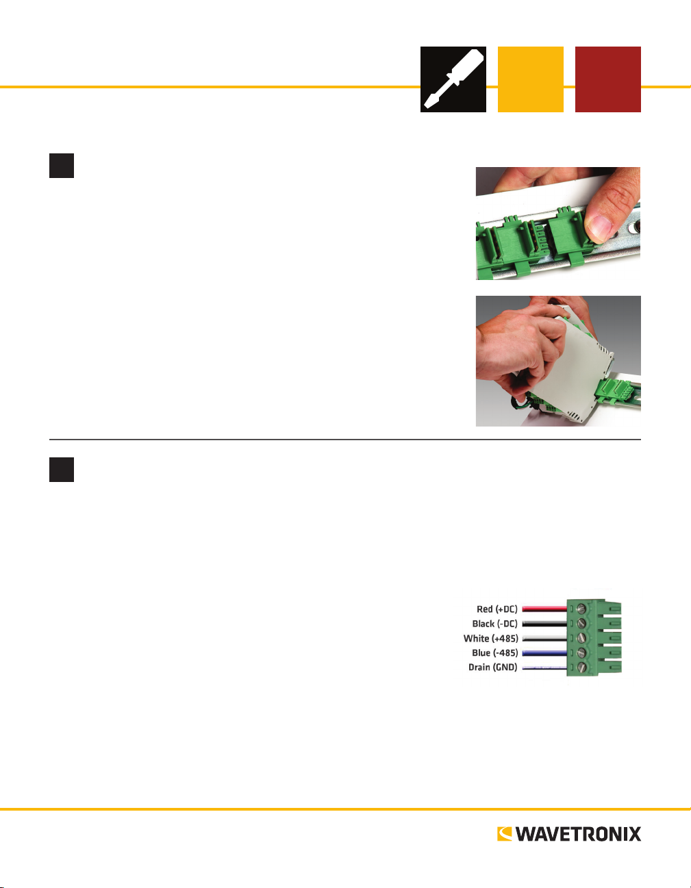
e Click 510 mounts over a T-bus for power and communication:
1 If the Click 510 was shipped with the T-bus connector attached, re-
move the connector from the module.
2 Snap the connector onto the DIN rail by positioning it over the rail
with the male connector pointing to the right. Hook one arm over the
edge of the DIN rail and press down on the other arm until it snaps
into place.
3 Connect the T-bus connector to the rest of the T-bus by sliding them
together until you hear them snap into place.
4 Mount the Click 510 onto the DIN rail: position it properly over the
T-bus connector, hook the lip over the lower edge of the DIN rail, and
use a rocking motion to snap the module into place.
Wire power and communication
2
If you are using a Click 200 surge protector with the Click 510, power and communication are provided to
the Click 510 through the T-bus (see the Click 200 Quick-Reference Guide). If you don’t have a Click 200
surge protector, use the following steps to wire power and communication into the Click 510:
1 Plug a T-bus 5-screw terminal block into the rst T-bus connector.
2 Wire DC power (10–30 V) from the power supply into the rst
screw terminal on the 5-screw terminal block; wire -DC into the
second screw terminal.
3 Connect RS-485 communication (+485, -485 and GND) to either
the remaining three screw terminals on the 5-screw terminal block
or to the screw terminals in the pluggable screw terminal block on
the top of the Click 510 (see labels for correct wiring).
e Click 510 has three other communication ports.
˽ RJ-11 jack – Connect a jumper cable here for RS-485 communication
˽ DB-9 connector – Connect a straight-through cable here for RS-232 communication
˽ RS-232/RS-485 terminals – On top of device; usually not used
www.wavetronix.com
801.734.7200
Page 2
Use on-device configuration features
3
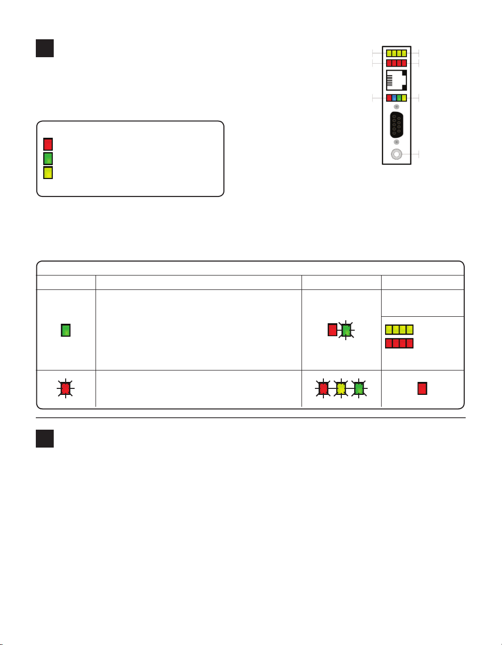
Yellow LEDs
Red LEDs
Sub Menu 1
Sub Menu 2
Next, use the device’s conguration features to make sure the Click
510 is wired and working properly. e Click 510 has four LEDs
that monitor device activity and help you select tasks and operat-
Multicolored LEDs
Main Menu
ing modes. It also
has two banks
LED activity-indicating functions:
Red – Shows device has power
Green – Shows device is transmitting data
Yellow – Shows device is receiving data
The blue LED has no activity-indicating function
of LEDs: one of
yellow LEDs that
represent sub-
Button
menu 1 and one of
red for submenu 2.
It also has a push-button, labeled Mode Switch, also used
for tasks and operating modes.
1 Check the LEDs to make sure the device has power.
2 Select the baud rate for the device by autobauding as outlined below. If you’d rather manually set the
baud rate, see Part 5 below.
LED task-indicating functions (operating mode functions will be covered later):
Selection Operating mode Running Completed
failure: will return to
previous mode
Autobaud – Hold the push-button down. Release it
when green LED is solid, then press quickly once, to
autobaud to sensor.
previous mode)
success
(will then
return to
Reset – Hold the push-button down. Release it when
red LED is blinking, then press quickly once, to reset to
factory defaults.
How to use the push-button to navigate through mode and task menus
4
Select a task or operation function by navigating though the main menu (multicolored LEDs) and the submenus (yellow and red LEDs) using the push-button as described below:
1 Enter the main menu and cycle through it by
holding the push-button down.
2 Release the push-button once the cycle reaches
the desired function.
3 Press the push-button again to select the func-
tion. Once selected, the function will either
start running or the rst submenu (yellow
LEDs) will start.
4 Hold the push-button to cycle through the rst
submenu.
5 Release the push-button once the desired sub-
menu selection is displayed.
6 Press the push-button again to select the func-
tion. Once selected, the function will either
start running or the second submenu (red
LEDs) will start.
7 Hold the push-button to cycle through the
second submenu.
8 Release the push-button once the desired sub-
menu selection is displayed.
9 Press the push-button again to select the func-
tion. e function will now run.
Page 3
Manually set baud rate (optional)
5
Note. is step is optional because if you prefer not to select the baud rate manually, you can also autobaud
the device (see Part 3).
1 Hold the push-button down, then release when the g 1 reen LED starts ashing.
2 Press the push-button again to select the baud rate task. e LED indicating the current baud rate will
turn on (see table).
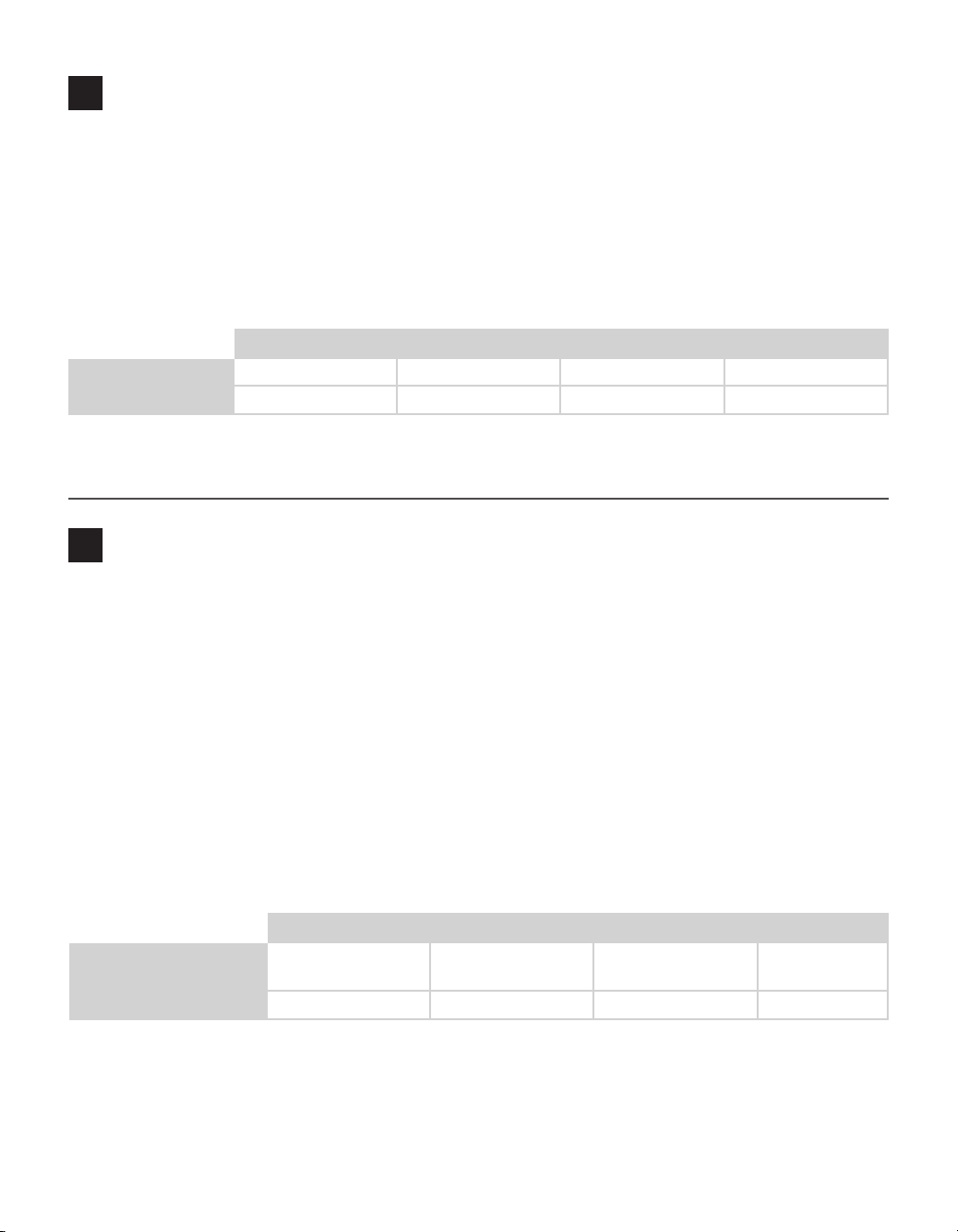
3 Hold down the push-button. e yellow LEDs will cycle through the eight possible baud rates, rst by
lighting up solid and then by ashing, as shown in the table below.
1st LED 2nd LED 3rd LED 4th LED
Yellow LEDs solid 1200 bps 2400 bps 4800 bps 9600 bps
Yellow LEDs flashing 19200 bps 38400 bps 57600 bps 115200 bps
4 Once you reach the baud rate you want, release the push-button, then press it once to select.
5 e device will return to the operating mode it was in before you started the baud rate task.
First test mode: Sensor Emulation
6
Sensor Emulation mode tests connections between a sensor and other devices. e Click 510 can mimic a
SmartSensor 105 and send trac data, allowing you to see if breaks in communication are caused by the
communication channel or by the sensor itself. It also allows you to check the functionality of an assembled
trac cabinet before attaching a sensor. In both these cases, the device should be connected to a contact
closure module such as the Click 100 or 172/174 so the response can be monitored.
1 Hold the push-button down, then release when the blue LED starts ashing.
2 Press the push-button to select. e rst yellow LED will turn on to let you use that submenu.
3 To pick how oen the device will send data, hold down the push-button and it will cycle through the
time options shown in the table below. Release when you reach one you want.
4 Press the push-button to select. e rst red LED will turn on to let you use that submenu.
5 To pick what kind of data the device will send, hold down the push-button and it will cycle through the
trac options shown in the table below. Release when you reach one you want.
6 Press the push-button to select.
1st LED 2nd LED 3rd LED 4th LED
Submenu 1 (Yellow LEDs) 1 second 0.25 – 1 second Switch (when push-
button is pressed)
Submenu 2 (Yellow LEDs) 17'–60' 30–60 mph Random trac Diagnostic trac -
7 Connect the device to a contact closure device, such as a Click 172/174. Set up the contact closure
device (see the pertinent quick-reference guide) and the mode will begin to run. As the mode runs, the
blue LED will ash fast and the submenu LEDs will light up if the Click 510 is pushing data. Monitor
the contact closure device to see if data is received.
-
Page 4
Second test mode: Test Pattern
7
Test Pattern mode tests communication channels by sending data packets over the channel. It’s helpful for
debugging because it locates the break in your channel of communication. To use it, connect two Click 510
devices together or connect a Click 510 to a computer. e responses can be monitored with serial terminal
soware or by watching the LEDs on the receiving 510.
1 Hold the push-button down, then release when the blue LED comes on solid.
2 Press the push-button to select. e rst yellow LED will turn on to let you use that submenu.
3 To pick how oen the device will send data, hold down the push-button and it will cycle through the
time options shown in the table below. Release when you reach one you want.
4 Press the push-button to select. e rst red LED will turn on to let you use that submenu.
5 To pick what kind of data the device will send, hold down the push-button and it will cycle through the
trac options shown in the table below. Release when you reach one you want.
6 Press the push-button to select. e mode will run. Observe the connected Click 510 or computer to
monitor that the packets are being received.
1st LED 2nd LED 3rd LED 4th LED
Submenu 1 (Yellow LEDs) 1 second 0.25 – 1 second Switch (when push-
button is pressed)
Submenu 2 (Yellow LEDs) LED flash LED sequence ASCII sequence ASCII text
-
See the Click Series User Guide for more information.
Third test mode: Latency Test
8
is test measures the time it takes data packets to travel across your communication channel. For this
mode, two Click 510 devices must be connected, with both of them set in this mode.
1 On both devices, hold the push-button down, then release when the yellow LED is solid.
2 Press both push-buttons to select. e results from the last latency test will appear in the LEDs.
3 Press the push-button again on either one of the devices to start the test.
4 While the test runs, the red and yellow LEDs will ash as the 510 tries dierent packet sizes.
When the test is nished, the results can be viewed in two ways:
˽ Before the test, connect via serial from a computer to the device that is initiating the test, then aer the
test, look at the results in a serial terminal program.
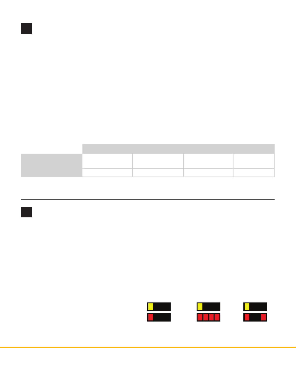
˽ Look at the LEDs on the device running the
test. See the graphic to the right for what the
LEDs mean.
See the Click Series User Guide for more infor-
Each red flash =
100 msec delay
Each red flash =
1 sec delay
Timed out or
corrupt data
mation.
© 2014 Wavetronix LLC. All rights reserved. Protected by US Pat. Nos. 6,556,916; 6,693,557; 7,426,450; 7,427,930; 7,573,400; 7,889,097; 7,889,098; 7,924,170; 7,991,542; 8,248,272;
8,665,113; and Cdn. Pat. Nos. 2,461,411; 2,434,756; 2,512,689; and Euro. Pat. Nos. 1435036; 1438702; 1611458. Other US and international patents pending. Wavetronix, SmartSensor, Click,
Command and all associated logos are trademarks of Wavetronix LLC. All other product or brand names as they appear are trademarks or registered trademarks of their respective holders. Product specifications are subject to change without notice. This material is provided for informational purposes only; Wavetronix assumes no liability related to its use.
WX-500-0194
 Loading...