

Page 1
Click 421 Serial to Bluetooth®
INSTALLER QUICK-REFERENCE GUIDE
Mount the device
1
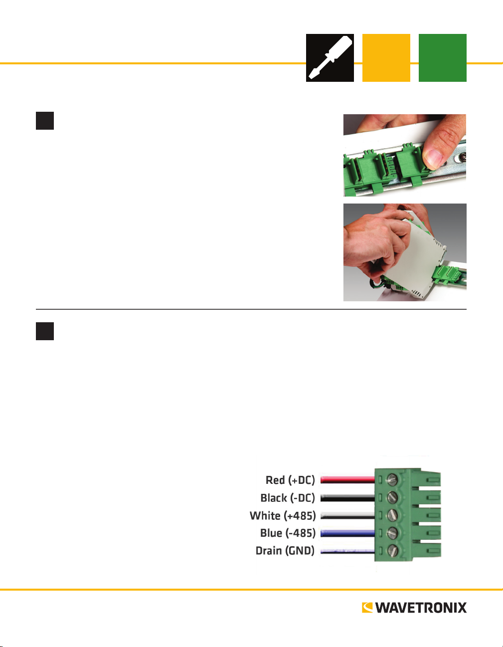
e Click 421 mounts over a T-bus for power and communication:
1 If the Click 421 was shipped with the T-bus connector attached, re-
move the connector from the module.
2 Snap the connector onto the DIN rail by positioning it over the rail
with the male connector pointing to the right. Hook one arm over the
edge of the DIN rail and press down on the other arm until it snaps
into place.
3 Connect the T-bus connector to the rest of the T-bus by sliding them
together until you hear them snap into place.
4 Mount the Click 421 onto the DIN rail: position it properly over the
T-bus connector, hook the lip over the lower edge of the DIN rail, and
use a rocking motion to snap the module into place.
Wire power and communication
2
If you are using a Click 200 surge protector with the Click 421, power and communication are provided to
the Click 421 through the T-bus (see the Click 200 Quick-reference Guide). If you don’t have a Click 200
surge protector, use the following steps to wire power and communication into the Click 421:
1 Plug a T-bus 5-screw terminal block into the rst T-bus connector.
2 Wire DC power (9–28 V) from the power supply into the rst screw terminal on the 5-screw terminal
block; wire -DC into the second screw terminal.
3 Connect RS-485 communication (+485, -485 and GND) to either the remaining three screw terminals
on the 5-screw terminal block or to the
screw terminals in the pluggable screw
terminal block on the top of the Click 421
(see labels for correct wiring).
e front of the Click 421 has one other communication port.
˽ DB-9 connector – Connect a straight-
through cable here for RS-232 communication
www.wavetronix.com
801.734.7200
Page 2
Attach the antenna
3
e Click 421 has a reversed polarity SMA antenna connector. A whip antenna can be used inside the
cabinet, though if it is inside a metal cabinet, the range will be diminished. An external antenna can also be
mounted on the exterior of the trac cabinet or up on a pole for maximum range. In that case, it is recommended you use a Click 250 wireless surge protector:
1 Connect the reversed polarity SMA connector of a coax cable to the Click 421 (antenna must be re-
moved), and connect the N connector to the nonbulkhead end of the Click 250.
2 Connect the N connector of another coax cable to the bulkhead end of the Click 250, and connect the
other end of the cable to the external antenna.
3 Attach a 12 AWG stranded copper grounding wire to the Click 250, then connect the grounding wire to
earth ground.
Use on-device configuration features
4
Use the device’s
conguration
features to make
sure the Click 421
is wired and working properly. e
Click 421 has four
LED activity indicating functions:
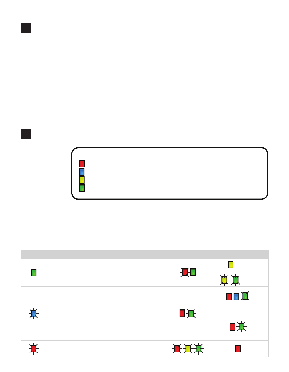
Red – Device has power
Blue – Shows when a link is successfully made over Bluetooth to an external device
Yellow – Device is transmitting data
Green – Device is receiving data
LEDs that monitor device activity
and help you select operating modes, as well as a push-button, labeled Mode Switch, also used for operating
modes.
1 Check LEDs to make sure the device has power.
2 Autobaud device to make sure it can talk to the sensor or other attached serial device (see table).
Hold the push-button to cycle through modes, then release when the desired mode is reached.
Selection Operating mode Running Completed
failure
Autobaud – Release push-button when green LED is solid to
autobaud to sensor.
Link Test (server) – Release push-button when blue LED is
blinking to perform a link test. The link test is covered in Part
10.
Reset – Release push-button when red LED is blinking to
reset to factory defaults.
connection established
connection not established
success
(LEDs on indefinitely)
Page 3

Connect via laptop or handheld computer
5
e Click 421 cannot initiate a connection; that must be done by a
laptop or handheld computer with Bluetooth capabilities:
1 Open the Bluetooth Manager program on the laptop or hand-
held.
2 Discover available Bluetooth devices.
3 Select the Click 421 from the list. It will appear under the name
“CK421-xxxxxxx” where the string of x’s represents the device
serial number. If you’d like to change the name of your Bluetooth
device, that will be covered in the next four parts of this document.
Note. Depending on your computer, you may be asked for a password
during the connection process, even if you haven’t set one up; if so, use the password “default.”
Install Click Supervisor
6
Note. Your Click 421 is now fully functional. If you don’t wish to make any other
changes to conguration, you don’t need to follow parts 6–9. However, the Click
421 can be further congured using Click Supervisor soware. Click Supervisor
will enable you to change the Bluetooth device name and other settings.
Follow these steps if you want to install Click Supervisor:
1 Download the setup le from www.1 wavetronix.com (under Support).
2 Open the le to run the setup wizard. Follow the steps to install.
Make a connection
7
To make a connection to your Click 421:
1 Make sure there is a connection between the Click 421 and the computer that Click Supervisor is on.
is link is available through the Bluetooth connection, but if for some reason the Bluetooth link is not
available—for instance, the computer that Click Supervisor is on does not have Bluetooth capabilities—
this can be made through the DB-9 connector on the front of the module or through a DB-9 connector
on another device that is also on the T-bus.
2 Run Click Supervisor and select Communication. is screen lets you pick the
type of connection you want to make, serial or IP. In most cases, the Click 421
will be congured using serial communication.
3 Click Settings to make any necessary changes to the settings, such as the port or
the baud rate. Click OK to return to the Communication screen, then click Connect. Keep the Click ID set to 0.
4 In the next screen, Click Supervisor will display all the devices it discovers.
When the Click 421 appears, select it and click Select. Click Supervisor will connect to the device.
Page 4

Select a driver
8
1 Select Setup Click on the main screen. You will see these drivers:
˽ SmartSensor – is driver is used if you plan on connecting from a laptop to Click
421 to your sensor. It has basic conguration settings.
˽ Expert – is driver exposes all settings, most of which should be used only when
instructed to by Wavetronix Technical Services. However, this driver lets you set a
Bluetooth name, signal trasmit power, and password.
2 Select the driver you want and click OK.
Configure the module
9
As mentioned in Part 5, your Click 421 can function properly without any settings being changed in Click
Supervisor. e settings listed below can be changed, but it is not necessary to do so.
SmartSensor Driver
˽ Description/Location – For
informational/identication
purposes.
˽ Device ID – Changes the device
ID number.
˽ Baud rate – If connecting to a
sensor, this must match the sensor’s baud rate.
Verify the connection
10
For verifying the connection, see Part 3 or follow the steps below to perform a link test on the device.
1 Press the push-button on the faceplate of the device, then release when the blue LED blinks. While the
link test is running, the red LED will glow solid and the green LED will blink.
2 Watch the LEDs. e blue LED will come on to indicate that there is a connection to the external Blue-
tooth device you connected to in Part 5. If the connection is no longer valid, the blue LED will never
come on and the device LEDs will remain in the state outlined in step 1.
3 To check if the data being pushed to the laptop or handheld is good, open a ter-
minal emulation program such as HyperTerminal and connect to the Bluetooth
device. Observe the data being received. It should be the alphabet repeated continuously; if nothing comes or any letters are missing, the data is not being received
or is corrupted.
4 Once the test is complete, the devices must be taken out of Link Test mode in order to operate. Press
and release the push-button to exit the mode.
Expert Driver (Bluetooth Tab)
˽ Bluetooth Name – Changes this makes it
easier to identify your Click 421 when connecting with an external device.
˽ Power Level – Changes the Bluetooth trans-
mit power.
˽ Password – Lets you set a password to be
used when making a Bluetooth connection
to this device.
© 2014 Wavetronix LLC. All rights reserved. Protected by US Pat. Nos. 6,556,916; 6,693,557; 7,426,450; 7,427,930; 7,573,400; 7,889,097; 7,889,098; 7,924,170; 7,991,542; 8,248,272;
8,665,113; and Cdn. Pat. Nos. 2,461,411; 2,434,756; 2,512,689; and Euro. Pat. Nos. 1435036; 1438702; 1611458. Other US and international patents pending. Wavetronix, SmartSensor, Click,
Command and all associated logos are trademarks of Wavetronix LLC. All other product or brand names as they appear are trademarks or registered trademarks of their respective holders. Product specifications are subject to change without notice. This material is provided for informational purposes only; Wavetronix assumes no liability related to its use.
WX-500-0192
 Loading...