

Page 1

Click 100–400 Series
USER GUIDE
Page 2

Click 100–400 Series
USER GUIDE
www.wavetronix.com 78 East 1700 South Provo, Utah 84606 801.734.7200
Page 3

© 2014 Wavetronix LLC. All Rights Reserved.
Wavetronix, SmartSensor, Click, Command, and all associated product names and logos are trademarks of Wavetronix LLC. All other
products or brand names as they appear are trademarks or registered trademarks of their respective holders.
Protected by US Patent Nos. 6,556,916; 6,693,557; 7,426,450; 7,427,930; 7,573,400; 7,889,097; 7,889,098; 7,924,170; 7,991,542;
8,248,272; 8,665,113; Canadian Patent Nos. 2461411; 2434756; 2512689; and European Patent Nos. 1435036; 1438702; 1611458. Other
US and international patents pending.
e Company shall not be liable for any errors contained herein or for any damages arising out of or related to this document or the
information contained therein, even if the Company has been advised of the possibility of such damages.
is document is intended for informational and instructional purposes only. e Company reserves the right to make changes in the
specications and other information contained in this document without prior notication.
FCC Part 15 Compliance: e Wavetronix SmartSensor sensors comply with Part 15 of the Federal Communications Commission
(FCC) rules which state that operation is subject to the following two conditions: (1) this device may not cause harmful interference,
and (2) this device must accept any interference received, including interference that may cause undesirable operation. FCC compliance statements for applicable optional modules are to be found in the module specications. Unauthorized changes or modications
not expressly approved by the party responsible for compliance with the FCC rules could void the user’s authority to operate this
equipment.
Disclaimer: e advertised detection accuracy of the Wavetronix SmartSensor sensors is based on both external and internal testing,
as outlined in each product’s specication document. Although our sensors are very accurate by industry standards, like all other sensor manufacturers we cannot guarantee perfection or assure that no errors will ever occur in any particular applications of our technology. erefore, beyond the express Limited Warranty that accompanies each sensor sold by the company, we oer no additional
representations, warranties, guarantees or remedies to our customers. It is recommended that purchasers and integrators evaluate the
accuracy of each sensor to determine the acceptable margin of error for each application within their particular system(s).
WX-500-0055
04/2012
Page 4

Contents
Introduction 7
Using this Manual 7
Part I Introduction to the Click Series
Chapter 1 The Power Plant 11
Connecting to a Circuit Breaker 12 • Connecting AC Surge
Protection 12 • Connecting Power 13 • Wiring AC Power into
the Click 201/202/204 14
Chapter 2 T-bus Basics 17
Adding a T-bus to the DIN Rail 18 • Mounting Click Devices
18 • Wiring T-buses 18
Chapter 3 Wiring the Devices 21
Working with Screw Terminal Blocks 21 • RS-485 Communication 22 • RS-232 Communication 24
Chapter 4 Installing Click Supervisor 27
Installing Click Supervisor 28 • Microso .NET Framework 31
Chapter 5 Using Click Supervisor 33
Connecting to Your Computer 33 • Accessing the Communication Screen 34 • Serial Communication 35 • IP Communication 37 • Working with Modules 38
Part II Individual Click 100–400 Series Modules
Page 5

Chapter 6 Click 100 — 16 Output Contact Closure 43
Physical Features 44 • Troubleshooting 48
Chapter 7 Click 101 — Multi-sensor to Contact Closure 49
Physical Features 51 • Installation 54 • On-device Conguration 54 • Computer Conguration 55
Chapter 8 Click 104 — 4-channel DIN Rail Contact Closure 61
Physical Features 62 • Installation 64 • Conguration 65 •
Rotary Switch 66 • Front Panel Menu 67 • Click Supervisor 73
Chapter 9 Click 110 — 4-channel Contact Closure Eurocard 79
Physical Features 80 • Installation and Wiring 82 • Fail-safe
Mode 85 • Conguration 85 • DIP Switches 86 • Front Panel
Menu 92 • Click Supervisor 101
Chapter 10 Click 112/114 — Detector Rack Cards 107
Physical Features 108 • Installation and Wiring 109 • Conguration 111 • DIP Switches 112 • Front Panel Menu 115
Chapter 11 Click 120/121 — Relay 129
Physical Features 130 • Installation 130
Chapter 12 Click 172/174 — Contact Closure Rack Cards 133
Physical Features 134 • Installing and Wiring the Click
172/174 136 • Operation Modes 136 • Power and Conguration 139 • Verify Operation 141 • Fail-safe Mode 142 •
Troubleshooting 143
Chapter 13 Click 200 — Lightning Surge Protector 145
Physical Features 146 • Installation 147
Chapter 14 Click 201/202/204 — AC to DC Power Supply 151
Physical Features 152 • Installation 152
Chapter 15 Click 203 — UPS/Battery 155
Physical Features 156 • Installation 157 • On-device Conguration 158
Page 6

Chapter 16 Click 210 — AC Circuit Breaker 161
Physical Features 162 • Installation 162
Chapter 17 Click 211 — AC Outlet 163
Physical Features 164 • Installation 164
Chapter 18 Click 221 — DC Surge Protector 167
Physical Features 168 • Installation 168
Chapter 19 Click 222 — System Surge Protector 169
Physical Features 170 • Installation 171
Chapter 20 Click 223 — Dual-485 Surge Protector 175
Physical Features 176 • Installation 177
Chapter 21 Click 230 — AC Surge Protector 179
Physical Features 180 • Installation 180
Chapter 22 Click 250 — Wireless Surge Protector 183
Physical Features 184 • Installation 184
Chapter 23 Click 301 — Serial to Ethernet Converter 187
Physical Features 188 • On-device Conguration 189
Chapter 24 Click 304 — RS-232 to RS-485 Converter 207
Physical Features 208 • On-device Conguration 209 • Computer Conguration 210
Chapter 25 Click 330/331 — Unmanaged Switches 219
Physical Features 220 • Installation 221 • Switching Characteristics 222
Chapter 26 Click 340/341/342 — Managed Switches 225
Physical Features 226 • Installation 228
Chapter 27 Click 400 — 900 MHz Radio 229
Page 7

Physical Features 230 • On-device Conguration 231 • Computer Conguration 233
Chapter 28 Click 421 — Serial to Bluetooth® Radio 245
Physical Features 246 • On-device Conguration 247 • Computer Conguration 249
Page 8

Introduction
In the introduction
Using this Manual
Wavetronix Click products are a simple and cost-eective way to connect various trac
components into a single, unied system. With a broad range of easy-to-use products, the
Click line integrates quickly and operates in even the harshest conditions. Click devices
provide the power and communication solutions needed for eective trac control and
management.
e Click series is divided into ve smaller, numerically based series. Each device in a particular series shares common elements, functions, etc.:
Click 100 series – Contact closure devices
Click 200 series – Power and surge protection devices
Click 300 series – Wired communication devices
Click 400 series – Wireless communication devices
Click 500 series – Customizable devices built on our Click 500 platform
is user guide covers the Click 100–400 series. For the Click 500 series, please see the Click
500 Series User Guide.
Using this Manual
is manual is divided into two parts:
Part I: Introduction to the Click Series – is part contains information common to
the Click line, beginning with basic module installation guidelines. It then covers the
Page 9

8 INTRODUCTION CLICK 100–400 SERIES USER GUIDE
Click Supervisor soware, which is used with certain Click devices for conguration.
For a list of Click 100–400 series devices that use Click Supervisor, see the beginning
of Chapter 4.
A few Click devices dier from what is written in the common information chapters
in the way they are installed or the soware used to congure them. In the event that a
Click device departs from what is written in Part I, that dierence will be noted in that
device’s chapter in Part II.
Part II: Individual Click 100–400 Series Modules – is part contains a chapter for
every device (or set of devices, in some cases) in the Click 100–400 series. Each chapter has an introduction to the device along with a description of the device’s physical
features and, when pertinent, sections on installation, conguration, troubleshooting
and more.
Page 10

Part I
Introduction to the Click Series
Chapter 1 – The Power Plant
Chapter 2 – T-bus Basics
Chapter 3 – Wiring the Devices
Chapter 4 – Installing Click Supervisor
Chapter 5 – Using Click Supervisor
Page 11

Page 12
The Power Plant 1
In this chapter
Connecting to a Circuit Breaker
Connecting AC Surge Protection
Connecting Power
1
Power and surge protection are provided to your devices via the Click modules that make
up what is known as the power plant (see Figure 1.1). Assembling the power plant is the rst
step in installing your Click devices.
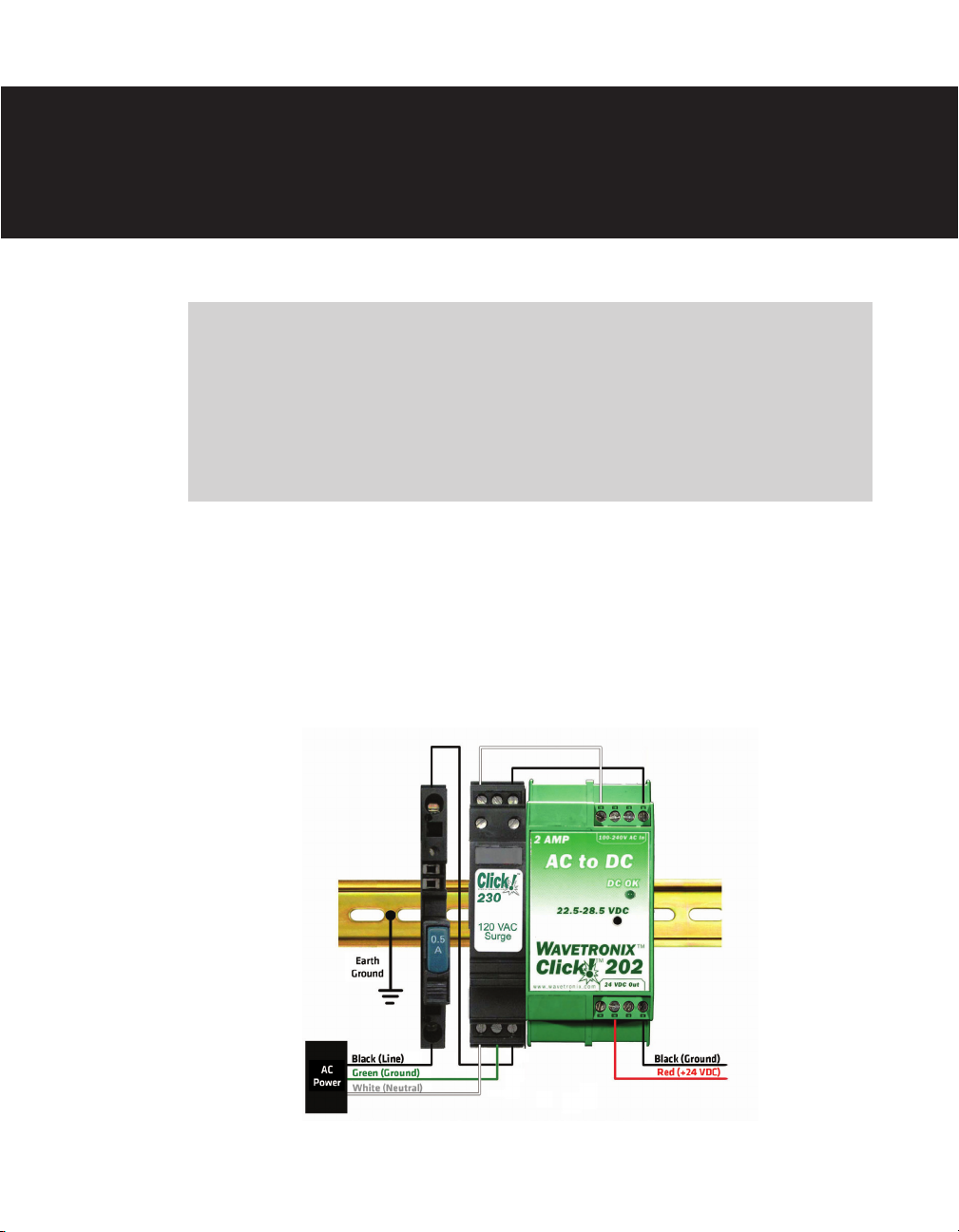
Figure 1.1 – The Click Power Plant
Page 13

12 CHAPTER 1 THE POWER PLANT
Note
The power plant will only be used if your cabinet is supplied with AC power. If DC is
coming into your cabinet, you will need the Click 221 DC surge protector, discussed in
Part II.
Connecting to a Circuit Breaker
e rst Click module you will connect is the Click 210, a circuit breaker designed to interrupt an electric current under overload conditions. e breaker is trip-free and can be easily
reset aer a current interruption by pushing the reset button (see the Click 210 chapter for
more information on this device).
To add a Click 210 circuit breaker and switch:
1 Using a rocking motion, mount the Click 210 onto the DIN rail.
2 Make sure the reset button on front of the module is pressed down before wiring.
3 Connect the black (line) wire from the terminal block or from the AC cord into one
side of the module.
4 Connect power out of the other side.
Note
It doesn’t matter which side is power in, as long as the opposite end is power out.
Connecting AC Surge Protection
e next module in the power plant is the Click 230, which provides surge protection to
other modules on the DIN rail (see the Click 230 chapter for more information on this device). Use these steps to include AC surge protection in your installation:
1 Using a rocking motion, mount the Click 230 onto the DIN rail next to the Click 210.
2 Connect the wire from the Click 210 to the rightmost screw terminal (terminal 5) on
the side of the Click 230 marked IN (see Figure 1.2).
3 Connect the white (neutral) and green (ground) wires from the AC terminal block or
from the AC cord into screw terminals 1 and 3, respectively, also on the side marked
IN.
4 Connect the outgoing neutral and power wires to screw terminals 2 and 6, respectively,
on the side marked OUT.
Page 14
CHAPTER 1 THE POWER PLANT 13
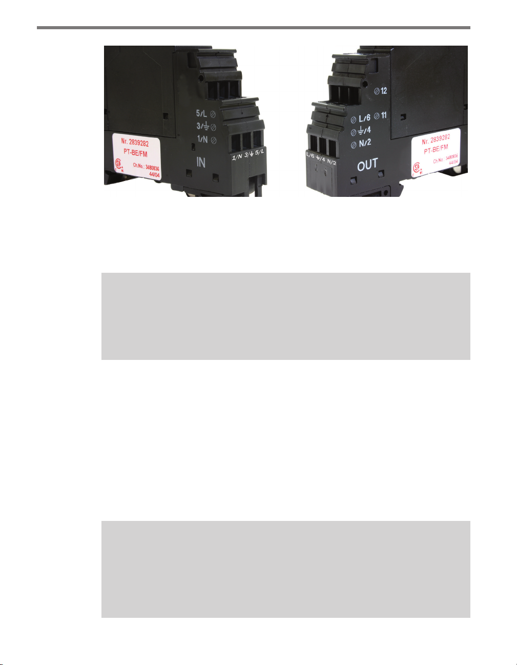
Figure 1.2 – Click 230 Screw Terminals (labels beneath terminals have been added)
Screw terminals 3 and 4 are directly bonded via the metal mounting foot of the base element to the DIN rail. ere is no need for any additional grounding between terminals 3
and 4 and the DIN rail.
Note
If you are using a Click 211 in your installation, the configuration of the power plant
will dier slightly from what is listed in this chapter, starting at this point in the
installation process. See the Click 211 chapter of this manual for more information.
Connecting Power
e nal component of the power plant is the AC to DC converter. e Click line features
several such converters. e Click 201/202/204 are AC to DC power supplies that provide
DC power to every Click product mounted on the DIN rail. e Click 201 provides 1 A, the
Click 202 provides 2 A and the Click 204 provides 4 A.
e screw terminals on the top and bottom of the Click 201/202/204 can be unplugged
from the module, allowing you to pre-wire power before the nal installation. e screw
terminal blocks are red-keyed, allowing the block to plug back into only one specic jack.
Note
If you prefer, instead of the Click 201/202/204, you can use the Click 203, which is a
combination UPS and battery. This set of modules will convert AC to DC and provide
uninterrupted power to your equipment. See the Click 203 chapter in Part II of this
document for more information.
Page 15
14 CHAPTER 1 THE POWER PLANT
Wiring AC Power into the Click 201/202/204
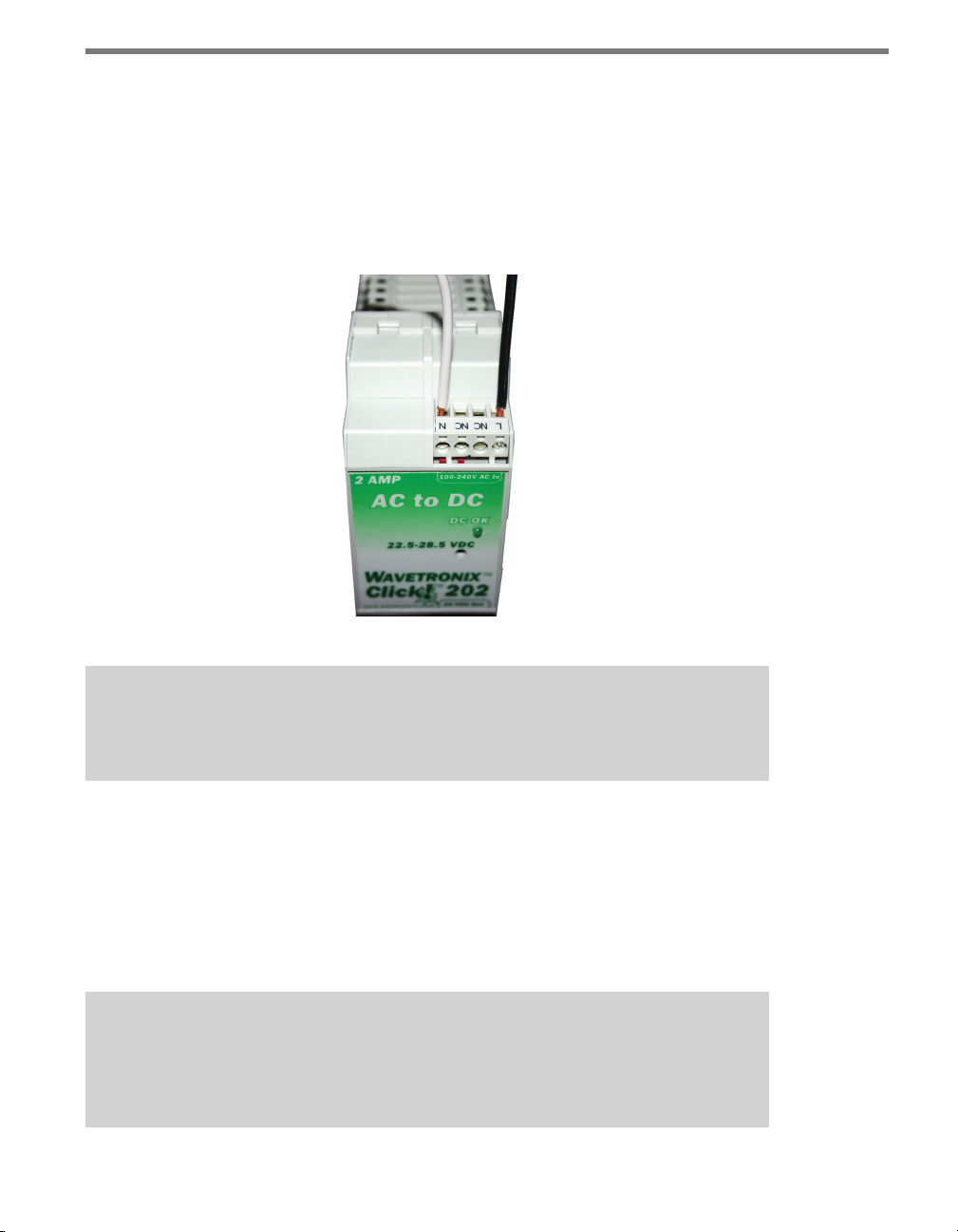
Use the steps below to properly wire AC power to the top of the Click 201/202/204:
1 Using a rocking motion, mount the Click 202/202/204 to the DIN rail next to the Click
230.
2 Connect the power and neutral wires from the Click 230 into the screw terminals
marked L and N, respectively, on the side of the module marked 100–240V AC In.
Figure 1.3 – Wiring AC Power into the Click 201/202/204
Caution
Make sure power to AC mains is disconnected while wiring the AC input.
Wiring DC Power out of the Click 201/202/204
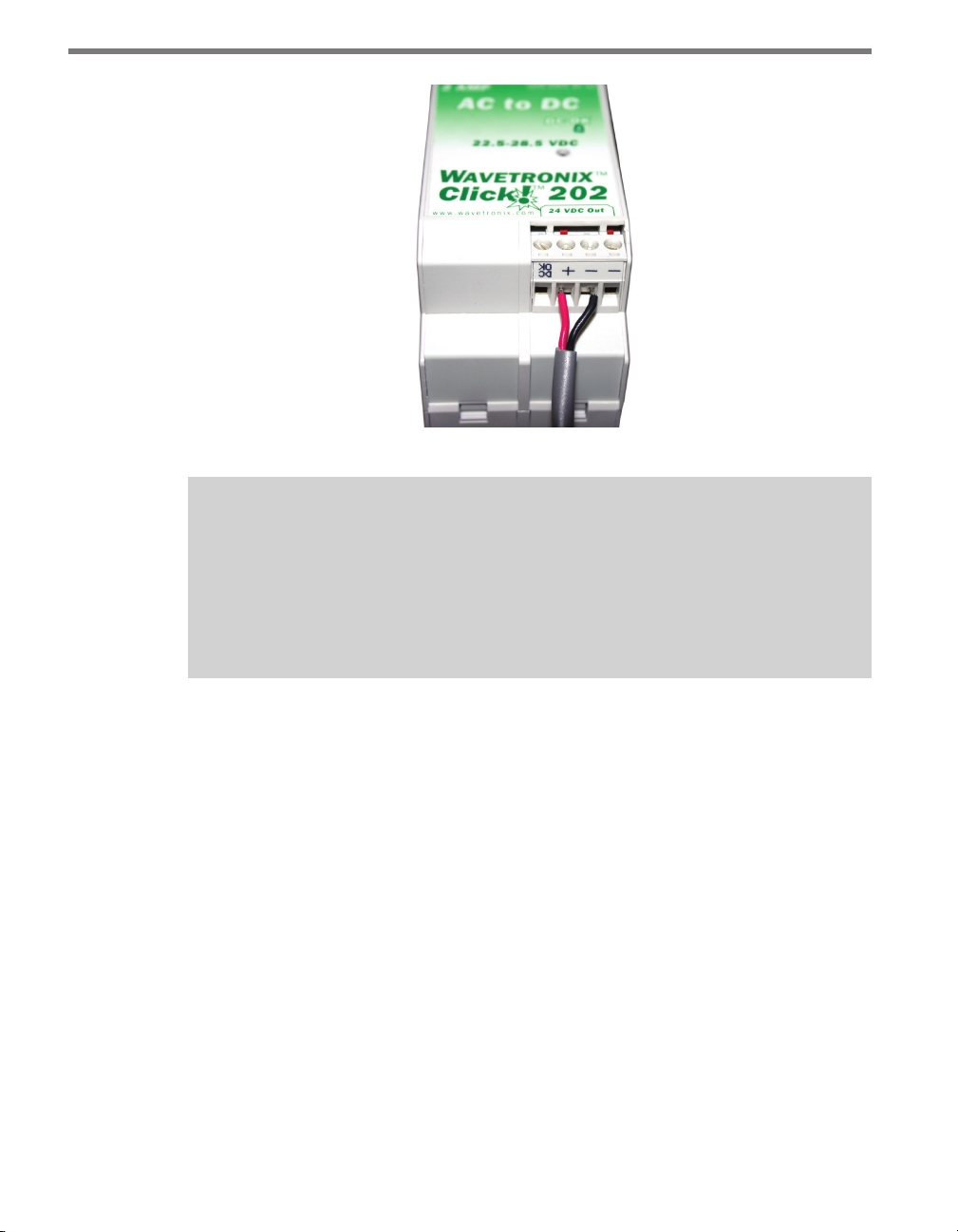
e screw terminals on the bottom of the devices are slightly dierent. e Click 202 and
204 have a single terminal block, while the Click 201 has two; it doesn’t matter which of
the two terminal blocks on the 201 you wire into. Connect one wire for DC power (red is
standard) to a screw terminal marked +. Connect a second wire as a ground wire (black is
standard) to either of the two terminals marked – (see Figure 1.4).
Note
Do not wire into the DCOK terminal; it provides only 20 mA and should only be used
to monitor the power supply.
Page 16
CHAPTER 1 THE POWER PLANT 15
Figure 1.4 – Wiring DC Power out of the Click 201/202/204
Caution
An authorized electrical technician should perform installation and operation of this
unit. Persons other than authorized and approved electrical technicians should NOT
attempt to connect this unit to a power supply and/or trac control cabinet, as there
is a serious risk of electrical shock through unsafe handling of the power source. Extreme caution should be used when connecting this unit to an active power supply.
Page 17

Page 18

T-bus Basics 2
In this chapter
Adding a T-bus to the DIN Rail
Mounting Click Devices
Wiring T-buses
2
Now that the power plant is complete, the next step in installing your Click modules is adding a T-bus to your DIN rail. A T-bus is made up of small modules called T-bus connectors
that snap onto your DIN rail to provide power and communication connections to your
Click devices. You can connect together as many T-bus connectors as you need to provide
power and communication to all the Click devices on the rail with only a single wiring connection.
Wavetronix has two varieties of T-bus connectors: green connectors, which conduct both
power and communication, and gray connectors, which only conduct power. Gray T-bus
connectors are used when you don’t want certain devices to communicate with each other.
In such a case, a gray connector placed between the two devices would prevent communication while still providing power.
Note
Wavetronix removes the communication lines from the gray T-bus connectors it provides. Gray T-bus connectors obtained from suppliers other than Wavetronix, however, will still have communication capabilities.
Page 19

18 CHAPTER 2 T-BUS BASICS
Adding a T-bus to the DIN Rail
Placing the T-bus on the DIN rail is quick and easy. To attach a T-bus connector to the rail,
simply position the connector over the rail with the male connector pointing to the right.
Hook one arm of the connector over one side of the DIN rail and press the other arm down
over the other side until the connector snaps in place. All the T-bus connectors you connect
together should be facing this direction.
To connect T-bus connectors together, simply slide them toward each other until you hear
them snap into place. To disconnect T-bus connectors, use a small, thin item, like a small
screwdriver, to gently pry the two modules apart.
Mounting Click Devices
To connect a Click device to the DIN rail and T-bus, simply position the device over the Tbus connector and, using the same rocking motion used to connect the devices in the power
plant, snap the device onto the DIN rail.
Note
Not all Click devices use the T-bus this way. Some devices, such as the 330, 331, 340,
341, 342, and those in the power plant, snap onto the DIN rail but not onto the T-bus.
For more information on how to install these devices, see the appropriate chapters in
Part II of this document.
Wiring T-buses
ere are two ways to provide power to a T-bus: wiring through a Click 200 and wiring
through a 5-screw terminal block.
Wiring through a Click 200
e Click 200 is a surge protection device that can be connected to a sensor. e Click 200
is unique among Click devices because it can take power and communications in through
its screw terminals and send it through any T-bus it is currently mounted on.
To provide power to a T-bus through a Click 200, follow these steps (see Figure 2.1):
1 Connect a Click 200 to a DIN rail and T-bus.
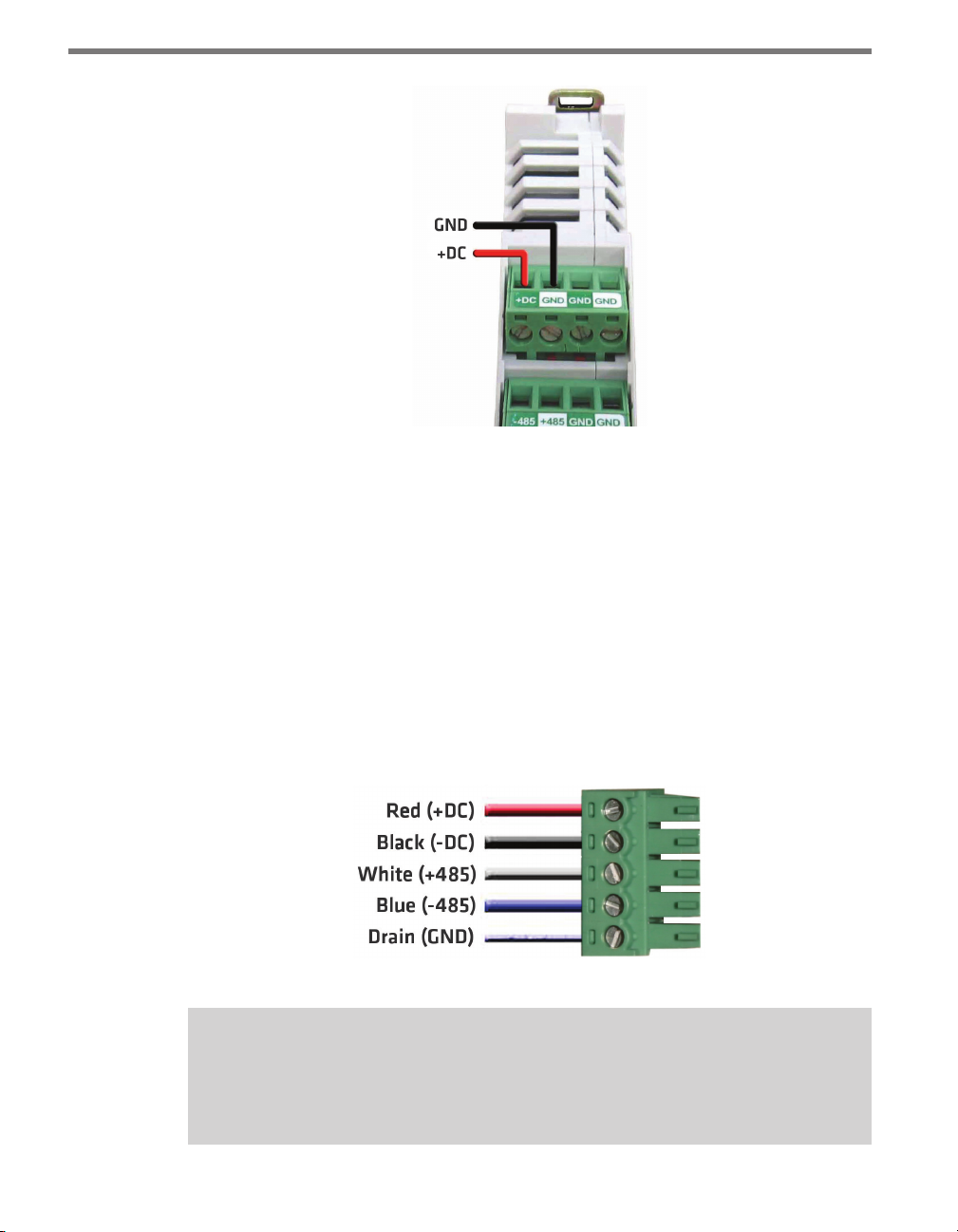
2 Connect the red (+24 VDC) wire from the Click 201/202/204 into the +DC screw ter-
minal on the side of the Click 200 marked PROTECTED.
3 Connect the black (ground) wire from the Click 201/202/204 into any of the terminals
marked GND on the same screw terminal block as the red wire.
Page 20
CHAPTER 2 T-BUS BASICS 19
Figure 2.1 – Wiring Power into the Click 200
Wiring through a 5-screw Terminal
If you choose not to use a Click 200, or if you have one but prefer not to wire through it,
you can also connect power through a 5-screw terminal block connected to the end of the
T-bus.
To provide power to a T-bus through a 5-screw terminal block, follow these steps:
1 Attach a male 5-screw terminal block to the le end of the T-bus by aligning it with the
rst connector and pushing the modules together.
2 Connect the black (ground) and red (+24 VDC) wires from the Click 201/202/204
into the top two screw terminals in the 5-screw terminal block (see Figure 2.2 for the
5-screw terminal block pinout).
Figure 2.2 – 5-screw Terminal Block Pinout
Note
To disconnect a 5-screw terminal block from a T-bus connector, use a small, thin item,
such as a small screwdriver, to gently pry the two modules apart.
Page 21

20 CHAPTER 2 T-BUS BASICS
Wiring out of a T-bus
Occasionally you will need to provide power and communication to devices in your cabinet
that are not on a DIN rail or on a T-bus. In these cases, you can connect a female 5-screw
terminal block to the right side of your T-bus and wire +DC, ground and communication
from there into the device.
Page 22

Wiring the Devices 3
In this chapter
Working with Screw Terminal Blocks
RS-485 Communication
RS-232 Communication
3
You are now ready to begin adding Click modules to your cabinet. For information on the
unique features of each of the devices in the Click line, see the corresponding chapter in
Part II of this document (or of the Click 500 Series User Guide).
Despite having dierent features, there are certain elements that are similar across devices.
Some of these, such as DIN rail mounting and the use of a T-bus for power and communication, have already been discussed. is chapter will discuss another such element: wiring
communication through the screw terminals.
Working with Screw Terminal Blocks
Many Click devices feature screw terminal blocks for wiring connections. ese screw terminal blocks simplify wiring because they can be removed from the Click device, then
wired and reinserted.
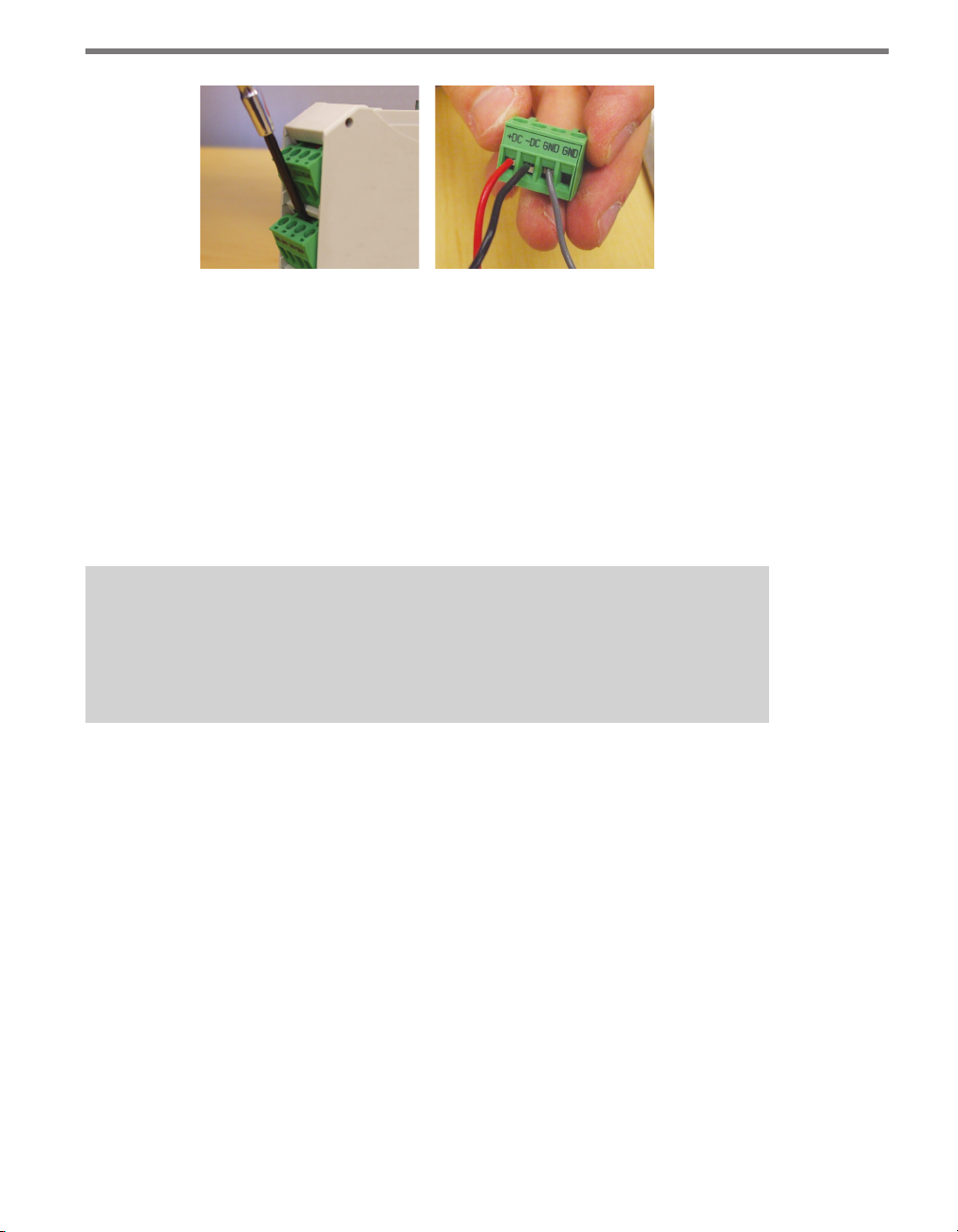
To remove a screw terminal block, insert a small, thin item, such as a small screwdriver, into
the gap between the screw terminal block and the Click device (just above the screw heads)
and gently pry the two apart.
Aer wiring, simply reinsert the screw terminal block and push until it snaps into place. e
screw terminal blocks are red-keyed, meaning they will only plug into their specic jacks.
Page 23
22 CHAPTER 3 WIRING THE DEVICES
Figure 3.1 – Removing and Wiring Screw Terminal Blocks
RS-485 Communication
Another feature that is common to many Click devices is RS-485 communication capabilities. RS-485 is important for Click devices because it is carried on the T-bus to all the Click
devices on a given DIN rail.
Connecting RS-485 communications to the Click devices on a DIN rail can be accomplished in two dierent ways: through a 5-screw terminal on the end of a T-bus, or through
a Click module, which will then communicate with the T-bus.
Note
The steps in this section are specifically for use with a Wavetronix SmartSensor cable. If you are using a dierent cable or wiring system, the colors of the wires used
will be dierent.
To connect through a 5-screw terminal, follow these steps.
1 Connect the +485 (white) wire from the terminal block or cable to the middle screw
terminal on the 5-screw terminal block connector you’re using for the T-bus in question
(see Figure 2.2 in the previous chapter for the pinout of the 5-screw terminal block).
2 Connect the -485 (blue) wire from the terminal block or cable to the middle screw
terminal on the 5-screw terminal block.
3 Plug the 5-screw terminal block into the T-bus.
To connect through any Click device with RS-485 ports, follow these steps:
1 Ensure that the Click device is mounted on a T-bus connector.
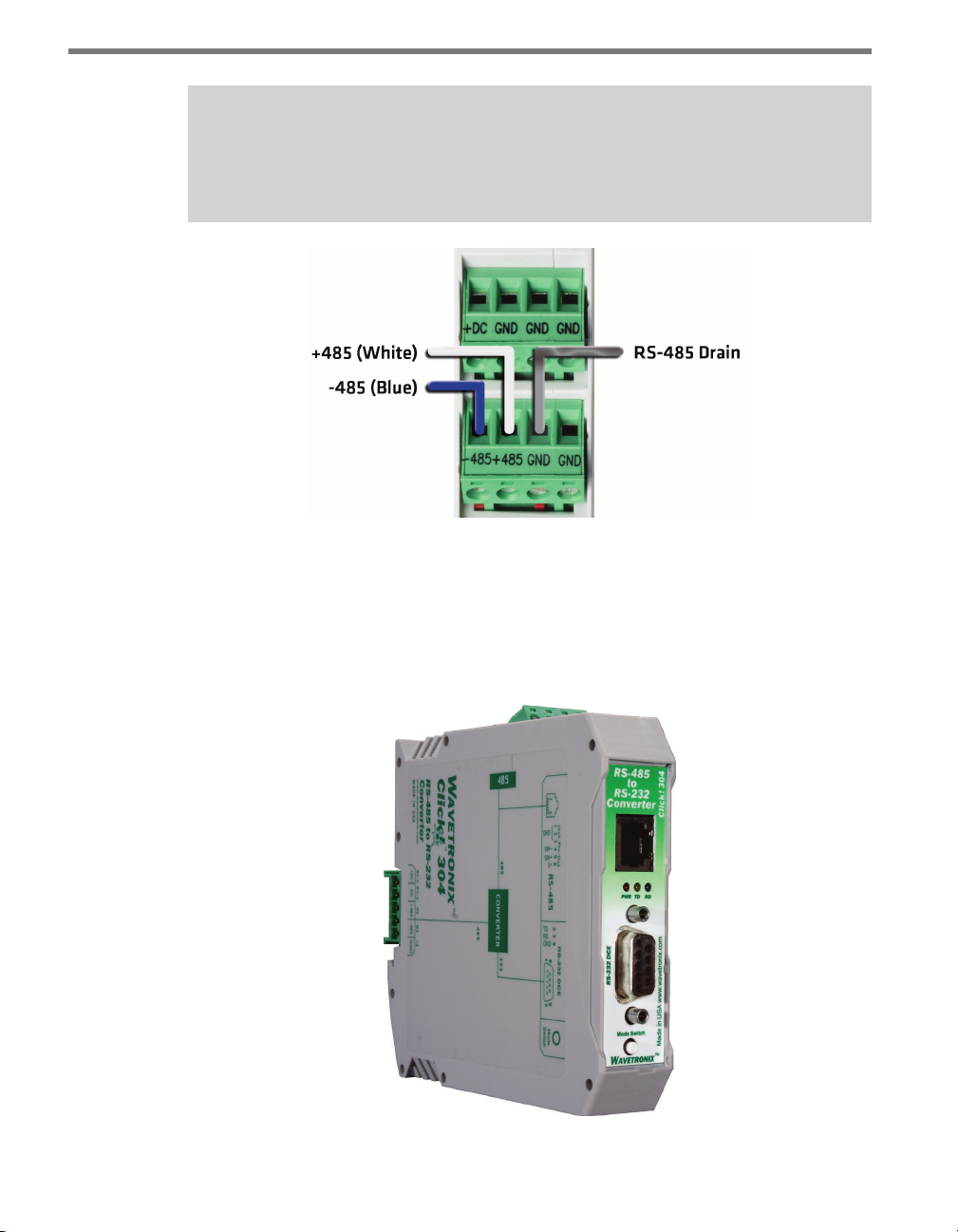
2 Connect the +485 (white) wire from the terminal block or cable to the terminal marked
“+485” in the screw terminal blocks (see Figure 3.2).
3 Connect the -485 (blue) wire from the terminal block or cable to the terminal marked
“-485” in the screw terminal blocks.
4 Connect the RS-485 drain wire from the terminal block or cable to a GND terminal in
the screw terminal blocks.
Page 24
CHAPTER 3 WIRING THE DEVICES 23
Note
If you are using a Click 200 in your installation, it is recommended you wire RS-485
through it if you would like to connect to a Click device.
Figure 3.2 – Wiring RS-485 Communication into the Click 200
Wiring RS-485 from a Click Device
Several Click devices—such as the 104, 110, 112/114, 172/174, 200, 301 and 304—also have
RJ-11 jacks for RS-485 communication with a computer or with contact closure cards. To
use, simply use an RJ-11 jumper cable to connect the two devices.
Figure 3.3 – A Click Device Showing RJ-11 and DB-9 Jacks
Page 25

24 CHAPTER 3 WIRING THE DEVICES
RS-232 Communication
Most Click devices also feature RS-232 communication capabilities. ese modules will
convert the RS-485 communication moving to and from the T-bus to RS-232. See below for
how to connect RS-232 to a laptop.
Several modules also have RS-232 screw terminals.
Note
The steps in this section are specifically for use with a Wavetronix SmartSensor cable. If you are using a dierent cable or wiring system, the colors of the wires used
will be dierent.
To use, follow the steps below:
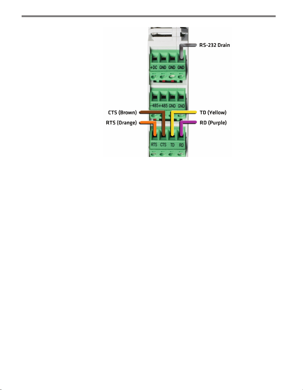
1 Connect the RTS (orange) wire from the cable or terminal block to the RTS screw ter-
minal on the protected side of the Click device (see Figure 3.4).
2 Connect the CTS (brown) wire to the CTS terminal on the protected side of the Click
device.
3 Connect the TD (yellow) wire to the TD terminal on the protected side of the Click
device.
4 Connect the RD (purple) wire to the RD terminal on the protected side of the Click
device.
5 Connect the RS-232 drain wire to a GND terminal on the protected side of the screw
terminal blocks.
Page 26
CHAPTER 3 WIRING THE DEVICES 25
Figure 3.4 – Wiring RS-232 Communication into the Click 200
Wiring RS-232 from a Click Device
Many Click modules feature an DB-9 jack for RS-232 communication with a laptop or other
such device. To use, simply use a straight-through cable to connect the two devices.
Page 27

Page 28

Installing Click Supervisor 4
In this chapter
Installing Click Supervisor
Microsoft .NET Framework
4
Once your Click devices are installed and wired, the next step is to install Click Supervisor, a computer program that will help you work with your Click modules. Most Click
devices can be congured and monitored to some extent using the buttons and LEDs on
the module, but certain devices can be ne-tuned using Click Supervisor. ese computerprogrammable devices include the following:
Click 101 – Multi-sensor to contact closure module
Click 104 – 4-channel DIN rail contact closure module
Click 110 – 4-channel contact closure Eurocard
Click 112/114 – Detector rack cards
Click 301 – Serial to Ethernet converter
Click 304 – Intelligent RS-485 to RS-232 converter
Click 306 – 1-port terminal server
Click 400 – Autobaud 900 MHz spread spectrum radio
Click 421 – Bluetooth® to serial converter
ere are also a number of Click 500 series devices that can be congured using Click Supervisor; these are discussed in the Click 500 Series User Guide.
Page 29
28 CHAPTER 4 INSTALLING CLICK SUPERVISOR
Note
If you are running Windows® Vista, you must run Click Supervisor in XP Service Pack
2 compatibility mode. To switch to this mode, right-click on the Click Supervisor icon
and select Properties from the drop-down menu. Go to the Compatibility tab. Under
Compatibility mode, click the Run this program in compatibility mode for: checkbox. This will enable the drop-down menu, allowing you to select Windows XP (Service Pack 2). Hit OK.
Installing Click Supervisor
If you have a Wavetronix Install Kit, the handheld computer included in the kit comes with
Click Supervisor already installed, along with sensor soware. If you don’t have an install
kit, or if you want to install on a desktop computer, follow the steps below.
Click Supervisor can be run on a Windows® PC and on ahandheld computer Everything
needed to install Click Supervisor is contained in the Click Supervisor Setup.exe le. e
setup program can install Click Supervisor on a PC, handheld computer or both.
Note
You must have administrator rights to run the setup program.
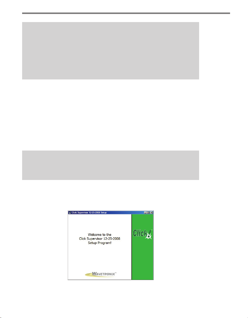
e soware can be downloaded from the Wavetronix website at www.wavetronix.com. After downloading the setup le, double-click on it to run the Click Supervisor setup wizard
(see Figure 4.1).
Figure 4.1 – Click Supervisor Setup Wizard
Page 30
CHAPTER 4 INSTALLING CLICK SUPERVISOR 29
To install Click Supervisor on a handheld computer, you need to have ActiveSync (on Windows XP or earlier) or Windows Mobile Device Center (on Windows Vista). If you do not
have these programs, they are available for download on the Microso website.
If you do not have ActiveSync or Windows Mobile Device Center installed on your computer, skip to the next section, titled Installing Click Supervisor on a PC.
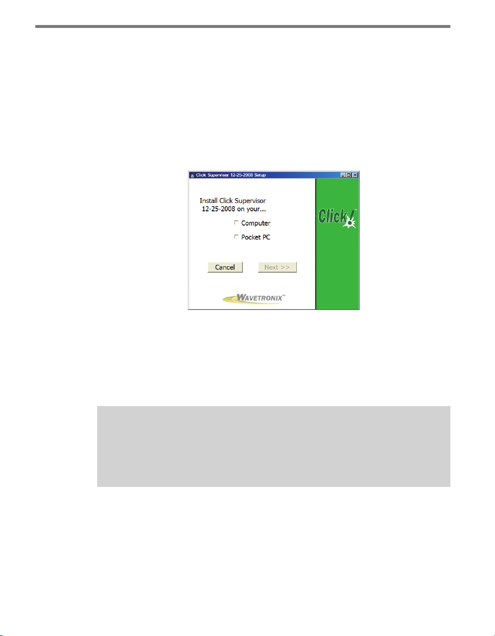
If you do have ActiveSync or Windows Mobile Device Center installed on your computer,
the setup program will detect this and the next screen that comes up will prompt you to select where you want to install Click Supervisor: a PC, a Pocket PC, or both (see Figure 4.2).
Figure 4.2 – Selecting an Installation
If you select Computer, the program will go through the steps outlined in the next section,
Installing Click Supervisor on a PC. If you select Pocket PC, the program will go through
the steps in the section titled Installing Click Supervisor on a handheld computer. If you
select both, the program will go through both installation processes, beginning with installing on the PC.
Note
Although the software can be installed on most handhelds, because of constantly
changing handheld technologies, Wavetronix can only oer technical support on the
handheld in the kit, which is a Socket Mobile 650.
Installing Click Supervisor on a PC
Follow these steps to install Click Supervisor on a PC:
1 On the screen shown in Figure 4.2, click the checkbox labeled Computer and then
select Next > >.
2 Select an installation location. e default location provided is normally “C:\Program
Files\Wavetronix.” Click Browse to choose another location (see Figure 4.3).
Page 31

30 CHAPTER 4 INSTALLING CLICK SUPERVISOR
Figure 4.3 – Location to Be Installed
3 Click the Install Now button.
4 Aer Click Supervisor is installed, you can create shortcuts to the soware on the desk-
top and in the start menu using the corresponding checkboxes on the nal screen (see
Figure 4.4). If no shortcuts are desired, uncheck the corresponding boxes. If you are
installing on a Pocket PC at the same time, this screen will not appear until both installations are complete.
Figure 4.4 – Shortcut Options
5 Click the View release notes when nished checkbox to view the Click Supervisor
release notes. e release notes contain additional information about the current version of the Click Supervisor soware. A PDF reader program such as Adobe Acrobat
Reader is required to view the release notes.
6 Click Finish to complete the setup process.
Installing Click Supervisor on a Handheld Computer
Although the soware can be installed on many handheld computers, because of constantly
changing handheld technologies, Wavetronix can only oer technical support on the handheld in the kit, which is a Socket Mobile 650.
Page 32

CHAPTER 4 INSTALLING CLICK SUPERVISOR 31
Use these steps to install Click Supervisor on a handheld computer:
1 Ensure that you have ActiveSync or Windows Mobile Device Center installed and that
the handheld is connected to the PC and synced.
2 On the screen shown in Figure 4.2, click the checkbox labeled Pocket PC and then
select Next > >.
3 On the next screen, click Continue > > to start the installation process (see Figure
4.5). e setup program runs the Add/Remove Programs application for Windows
handheld devices. If a handheld device is connected to the computer, Add/Remove
Programs will immediately begin installing Click Supervisor on the handheld device.
If a device is not connected to the computer, Click Supervisor will be downloaded the
next time a handheld device is connected to the computer.
Figure 4.5 – Adding Click Supervisor to a Pocket PC
4 Click OK once the download is complete.
Microsoft .NET Framework
e Click Supervisor setup program will automatically detect whether Microso .NET
Compact Framework v1.1 is installed on your PC. If it is not installed, you will be prompted
to install it (see Figure 4.6).
Page 33
32 CHAPTER 4 INSTALLING CLICK SUPERVISOR
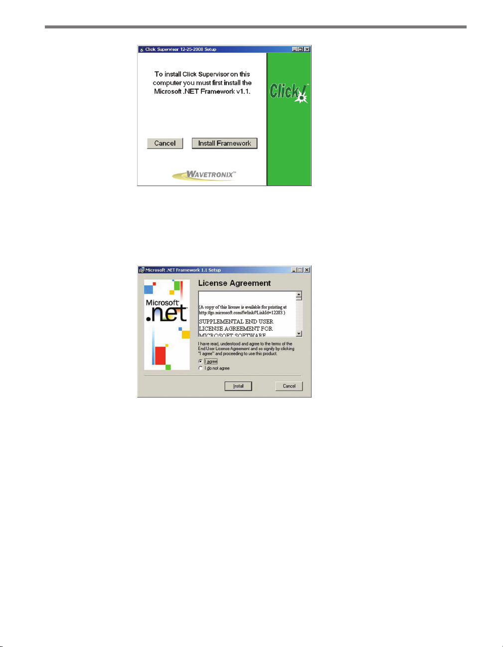
Figure 4.6 – Microsoft .NET Framework Prompt
Use the following steps to install Microso .NET Framework:
1 Click the Install Framework button.
2 Click the I Agree radio button when the License Agreement appears (see Figure 4.7).
Figure 4.7 – Microsoft .NET License Agreement
3 Click Install. A window will appear stating that the .NET Framework has been in-
stalled successfully.
4 Click OK and you will be returned to the Click Supervisor setup program.
Page 34

Using Click Supervisor 5
In this chapter
Connecting to Your Computer
Accessing the Communication Screen
Serial Communication
IP Communication
Working with Modules
5
Once you have Click Supervisor installed on your computer, you can begin using it to congure and monitor your Click devices.
Connecting to Your Computer
e rst step is to connect your computer to the Click modules on your DIN rail so that
Click Supervisor can see them. Click Supervisor can detect all computer-programmable
devices that are connected together by either a wired or wireless connection.
You can do this one of two ways. If you are using an Ethernet connection, you must be on
the same network with the Click device. Plug the Ethernet cable from your computer or
switch to the RJ-45 jack on the front of the Click 301. You must use a crossover cable to
connect your computer to the Click 301 via Ethernet.
If you are using a serial RS-232 connection, the computer needs to be connected by a
straight-through serial cable to the DB-9 connector on the front of any one of the computer-programmable devices on the T-bus. See the beginning of Chapter 4 for a list of Click
100–400 series devices that can be congured using Click Supervisor.
Page 35
34 CHAPTER 5 USING CLICK SUPERVISOR
Connecting the computer to another device that has a RS-232 port but is not computerprogrammable, such as the Click 200, will not allow Click Supervisor to communicate with
the other computer-programmable devices on the T-bus.
Accessing the Communication Screen
To connect to your devices with Click Supervisor, open the program by double-clicking on
it. It will bring you to the Click Supervisor main screen (see Figure 5.1).
Figure 5.1 – Click Supervisor Main Screen
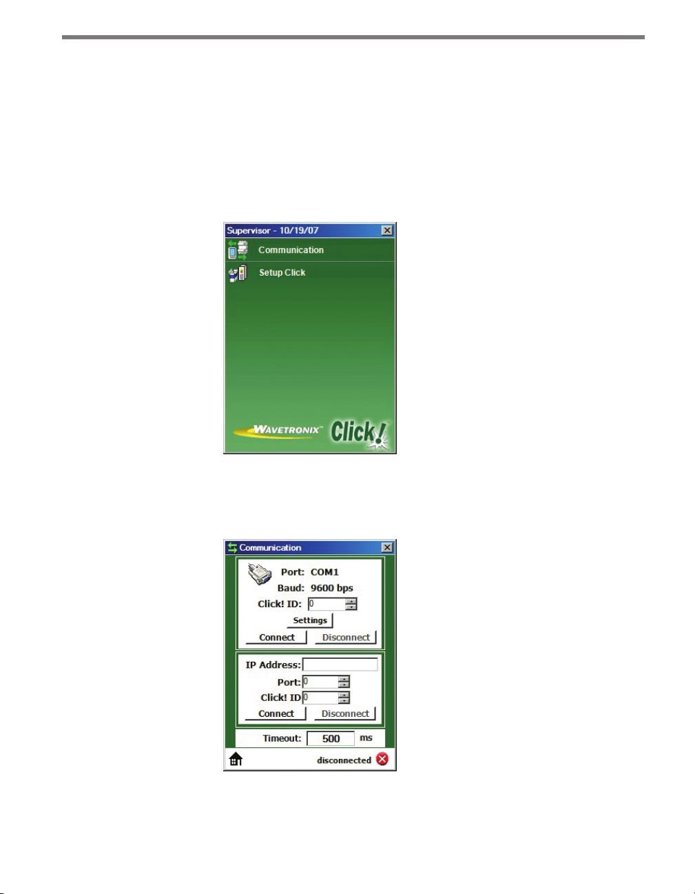
Click on Communication to access the Communication screen (see Figure 5.2). ere are
two ways to connect to your Click devices: through a serial connection or an IP connection.
Figure 5.2 – Communication Screen
Page 36

CHAPTER 5 USING CLICK SUPERVISOR 35
Serial Communication
e rst section on the Communication screen is Serial Communication. Here you can
connect to a Click device through an RS-232 cable.
Changing Settings
Click Settings to bring up the Serial Settings screen (see Figure 5.3).
Figure 5.3 – Serial Settings Screen
COM Port – Allows you to change the serial connection port.
Baud Rate – Allows you to change the baud rate or set it to auto-detect.
Flow Control – Is usually only used if you are connecting your computer to an RS-232
device that requires hardware handshaking.
Parity – Allows you to set parity error checking.
Stop Bits – Allows you to set the number of stop bits.
Data Bits –Allows you to set the number of data bits being sent.
Note
The flow control, parity, stop bits and data bits settings should not be changed unless you have been instructed to do so by Wavetronix Technical Services.
Click the Save as default settings checkbox to tell the soware to remember your setup. Click
OK to return to the Communication screen or Cancel to exit without saving your settings.
On the Communication screen, you can see the settings reected in the Port: and Baud:
entries. Port: shows the port you’ve set the program to communicate through, and Baud:
shows the baud rate, as set under Settings or as automatically detected.
Page 37

36 CHAPTER 5 USING CLICK SUPERVISOR
Connecting to a Device
Click Supervisor can talk to one device at a time. ere are two ways to select which module
to talk to.
Follow these steps if you know the Click ID number of the device:
1 Enter the ve-digit ID number in the Click ID text eld, either by typing or by using
the arrows to the right of the box.
2 Click Connect. Aer downloading the communication le, the program will return
you to the Click Supervisor main screen.
Note
You can find the Click ID number of your device by looking at the number beneath
the barcode. The ID number is the last five digits of this number. Each device on a rail
must have a unique number. The number it’s been assigned should be unique, but if
it is not, you can change it after connecting to the device. See that device’s chapter in
Part II of this guide for more information.
Alternatively, you can connect without the ID number:
1 Leave a 0 in the Click ID text eld. Click Supervisor will look for all connected devices
on the network.
2 Click Connect. e Device Selection screen will appear (see Figure 5.4). e comput-
er-programmable devices on the network will appear as they are detected. e device
list is divided into three columns: ID shows the ID number of the device, Click shows
the product number of the device, and Description shows the user-dened description
of the device.
Figure 5.4 – Device Selection
Page 38

CHAPTER 5 USING CLICK SUPERVISOR 37
3 Click on the device you’d like to connect to and hit Select. Aer downloading the com-
munication le, the program will return you to the Click Supervisor main screen.
Note
After connecting, you may see a dialog box asking if you’d like to upgrade. Each version of Click Supervisor has the newest firmware for all the Click devices, and when it
connects to a device it will check to see if the firmware in the program is newer than
that in the device. If it is, you will see the dialog box. If you’d like to upgrade your
device with the newest firmware, click Yes .
IP Communication
e second section on the Communication screen is IP Communication. To connect to
the devices on your network, rst enter the IP address assigned to the Click 301 (or other
Ethernet communication device connected to your modules), then enter the port number.
e default port number for the Click 301, as well as many other such devices, is 10001. e
default IP address is 172.16.0.13.
Once a connection is made, Click Supervisor will remember the information so you don’t
have to type it the next time.
Connecting to a Device
As with a serial connection, you must choose which device Click Supervisor will connect
to. ere are two ways to select which device to talk to.
Follow these steps if you know the Click ID number of the device:
1 Enter the ve-digit ID number in the Click ID text eld, either by typing or by using
the arrows to the right of the box.
2 Click Connect. Aer downloading the communication le, the program will return
you to the Click Supervisor main screen.
Note
You can find the Click ID number of your device by looking at the number beneath
the barcode. The ID number is the last five digits of this number. Each device on a rail
must have a unique number. The number it’s been assigned should be unique, but if
it is not, you can change it after connecting to the device. See that device’s chapter in
Part II of this guide for more information.
Page 39
38 CHAPTER 5 USING CLICK SUPERVISOR
Alternatively, you can connect without the ID number:
1 Leave a 0 in the Click ID text eld. Click Supervisor will look for all connected devices
on the network.
2 Click Connect. e Device Selection screen will appear, and aer a few moments, the
list will be populated with the computer-programmable devices on the network. e
list is divided into three columns: ID shows the ID number of the device, Click shows
the product number of the device, and Description shows the name of the device.
3 Click on the device you’d like to connect to and hit Select. Aer downloading the com-
munication le, the program will return you to the Click Supervisor main screen.
Note
After connecting, you may see a dialog box asking if you’d like to upgrade. Each version of Click Supervisor has the newest firmware for all the Click devices, and when it
connects to a device it will check to see if the firmware in the program is newer than
that in the device. If it is, you will see the dialog box. If you’d like to upgrade your
device with the newest firmware, click Yes .
Working with Modules
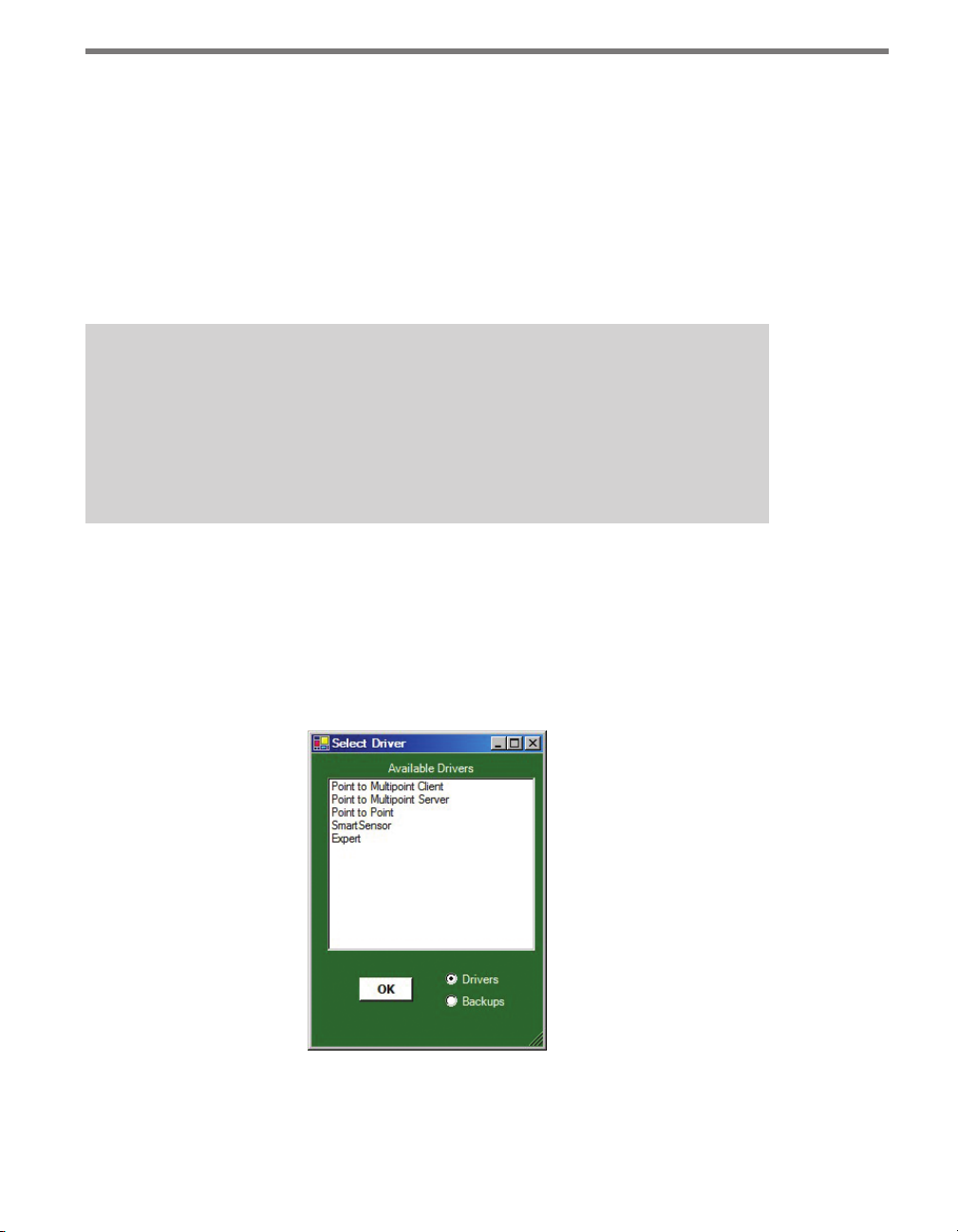
You will now be able to select Setup Click and choose a driver to start working with the
device (see Figure 5.5). e drivers under Setup Click will be dierent for every device you
connect to. For information on how to congure each device through Click Supervisor, see
that device’s chapter in Part II or in the Click 500 Series User Guide for more information.
Figure 5.5 – Selecting a Driver
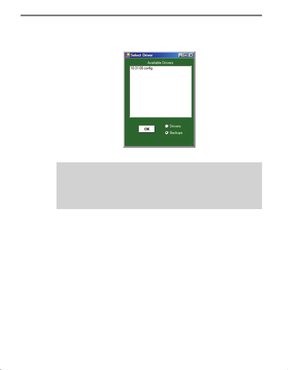
From the Select Driver screen, you can also access backups you’ve made of settings (how to
save these settings is discussed in each chapter in Part II that deals with Click Supervisor).
Page 40
CHAPTER 5 USING CLICK SUPERVISOR 39
To open a backup, select the Backups radio button in the lower righthand corner of the
screen. All the backups currently saved in the correct folder will appear (see Figure 5.6).
Select the backup you wish to open and click OK.
Figure 5.6 – Selecting a Backup
Note
The default folder to save backups in is C:\Program Files\Wavetronix\ClickHome\
Drivers\ [model number] \User. If you try to save the files elsewhere, the program will
still save them in the User folder.
Aer you’ve nished conguring a device, you can connect to another one by returning to
the Communication screen, closing the connection, and connecting to a dierent device.
Page 41

Page 42

Part II
Individual Click 100–400
Series Modules
Chapter 6 – Click 100
Chapter 7 – Click 101
Chapter 8 – Click 104
Chapter 9 – Click 110
Chapter 10 – Click 112/114
Chapter 11 – Click 120/121
Chapter 12 – Click 172/174
Chapter 13 – Click 200
Chapter 14 – Click 201/202/204
Chapter 15 – Click 203
Chapter 16 – Click 210
Chapter 17 – Click 211
Chapter 18 – Click 221
Chapter 19 – Click 222
Chapter 20 – Click 223
Chapter 21 – Click 230
Chapter 22 – Click 250
Chapter 23 – Click 301
Chapter 24 – Click 304
Chapter 25 – Click 306
Chapter 26 – Click 330/331
Chapter 27 – Click 340/341/342
Chapter 28 – Click 400
Chapter 29 – Click 421
Page 43

Page 44
Click 100 —
16 Output Contact Closure 6
In this chapter
Physical Features
On-device Configuration
Troubleshooting
6
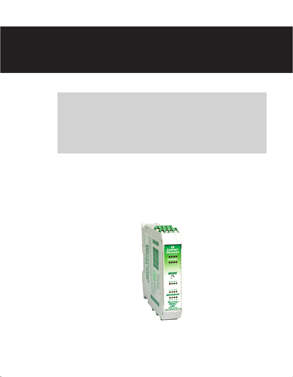
e Click 100 is a hot-swappable contact closure module for use with the Wavetronix
SmartSensor. It mounts onto a DIN rail and is connected to the SmartSensor through the
Click 200 surge protection module.
Figure 6.1 – The Click 100
Page 45
44 CHAPTER 6 CLICK 100
Physical Features
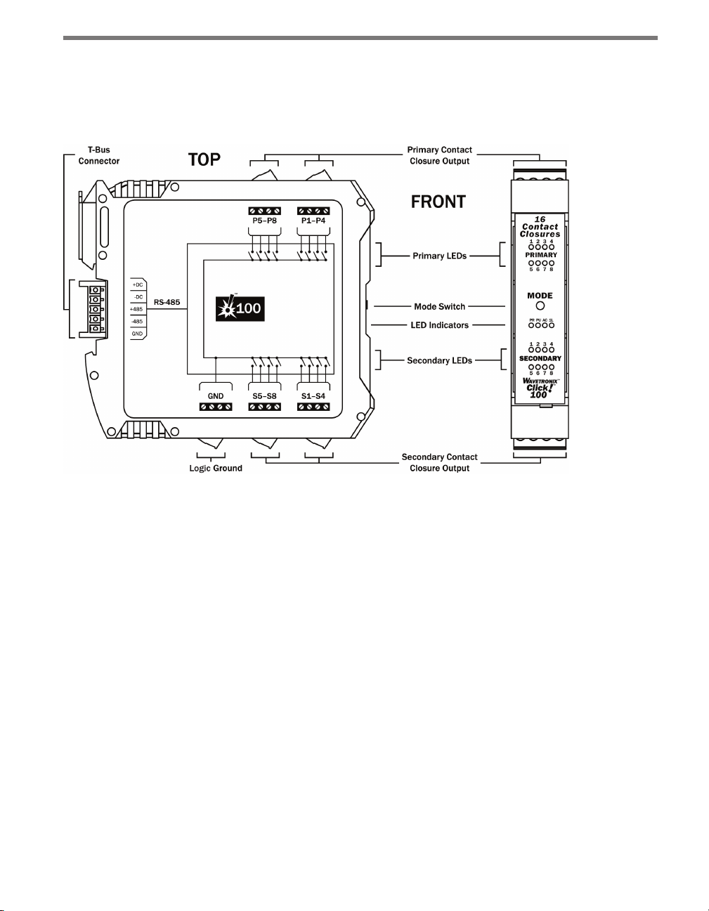
e Click 100 has eight primary and eight secondary contact outputs, which all share a logic
ground (see Figure 6.2).
Figure 6.2 – Diagram of Click 100
Communication Port
e back of the Click 100 features a 5-position connector that plugs into a T-bus connector
and provides power and RS-485 communication to the device. It also passes RS-485 communication from the Click 100 to all other devices on the T-bus when pressing the Mode
button during conguration (see the On-device Conguration section of this chapter for
more information).
Screw Terminals
e contact closure outputs are wired to a controller, data logger or BIU (Bus Interface
Unit) using the pluggable screw terminals on the top and bottom of the Click 100. e top
screw terminals are labeled 1–8 and represent the primary outputs. Primary 1 (P1) represents the lane closest to a side-re SmartSensor and the remaining outputs represent the
lanes as they sequentially get further from the sensor. For dual-loop emulation, the contact
closure outputs must be wired with the primary always leading the secondary (see Figure
6.3).
Page 46
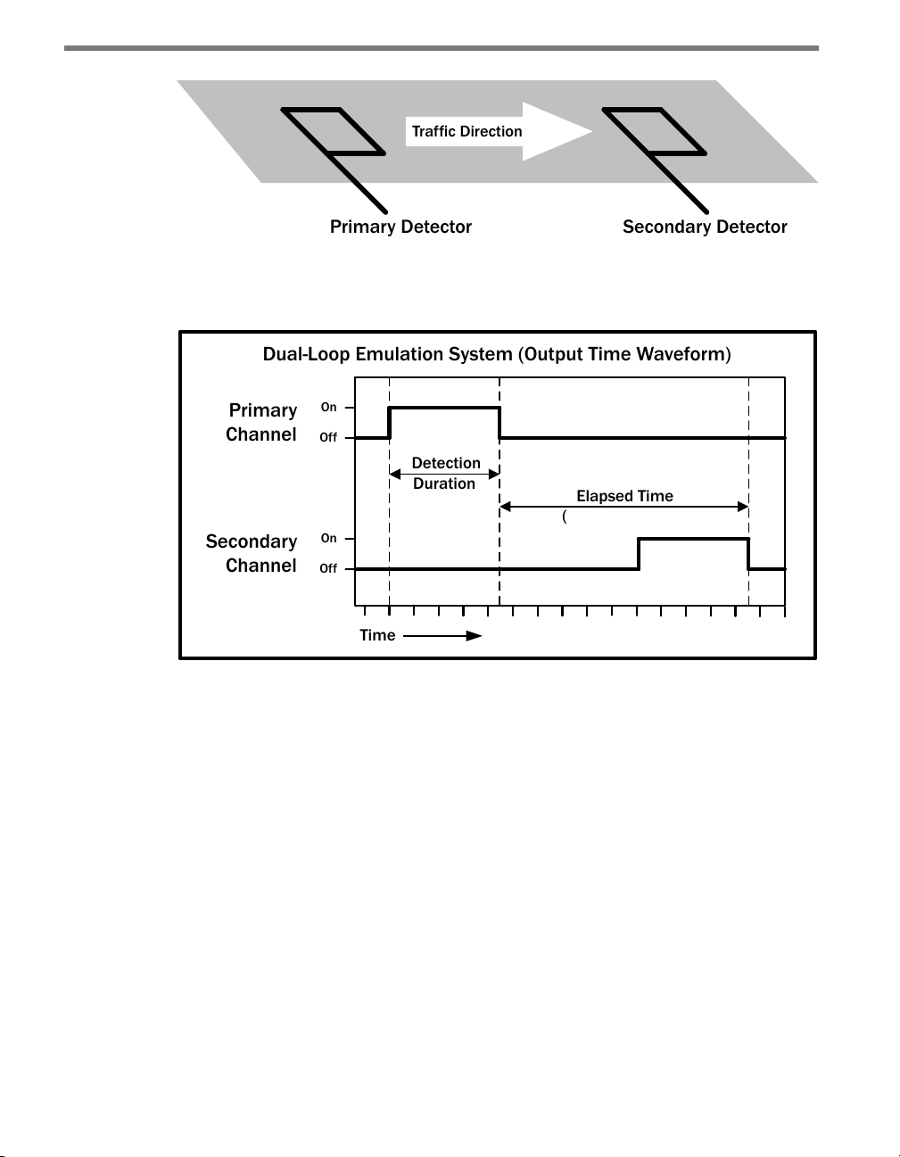
CHAPTER 6 CLICK 100 45
Primary Detector
Secondary Detector
Traffic Direction
Primary
Channel
Secondary
Channel
Time
Dual-Loop Emulation System (Output Time Waveform)
Elapsed Time
(
Detection
Duration
On
Off
On
Off
Figure 6.3 – Primary and Secondary Outputs
Figure 6.4 below shows a diagram of the output signal time waveforms of the two detectors.
Indicates Speed)
Figure 6.4 – Emulation System Output Waveforms
e bottom screw terminals are also labeled 1–8 and represent the secondary outputs, with
secondary one (S1) representing the lane closest to the SmartSensor. e remaining four
screw terminal connections are labeled GND and are a common logic ground for all 16
contact closure outputs. You must provide a connection from the GND terminals to a logic
ground to make the primary and secondary outputs operational.
e screw terminal connectors can also be unplugged from the Click 100 allowing you to
pre-wire the Click 100 before nal installation.
Configuration Features
e four LEDs located right below the push-button are used to indicate operation modes,
which will be discussed later in the On-device Conguration section of this chapter. Below
is a list of the four LEDs:
PR (Presence) – Red
PU (Pulse) – Orange
Page 47

46 CHAPTER 6 CLICK 100
AC (Actuation) – Green
1L (One Loop Speed) – Ye l low
e front also has a push-button labeled Mode Switch, which is used to cycle the Click 100
through operation modes. is will be discussed in the On-device Conguration section.
LEDs
e Click 100 module has sixteen contact closure outputs. Each output represents a primary or secondary channel and has a corresponding LED on the front of the Click 100 module.
e eight red LEDs on the top of the faceplate correspond to the primary outputs and the
eight yellow LEDs on the bottom of the faceplate correspond to the secondary outputs.
On-device Configuration
e Click 100 can be congured using the push-button in the middle of the faceplate.
To automatically congure the Click 100, press and hold the push-button until the green
LED ashes four times. e green LED and contact closure LEDs will ash during the autoconguration process, which normally takes 5–30 seconds. e auto-conguration process
matches the Click 100 with the sensor’s baud rate, loop size and loop spacing.
e rst four primary LEDs indicate the current baud rate at which the Click 100 is trying
to congure. e following table shows what the dierent ashing LEDs represent:
Primary LED Baud Rate
1 9400 bps
2 19200 bps
3 38400 bps
4 57600 bps
Table 6.1 – List of Baud Rates
Note
The maximum baud rate that can be used is 57600. If the sensor’s RS-485 bus is set
higher than 57600, no data will be seen on the Click 100.
e yellow LED will ash four times indicating the end of the auto-conguration process.
Once the Click 100 is congured, the device will be set to Presence (PR) mode.
Press the push-button until the desired operation mode is selected.
Page 48

CHAPTER 6 CLICK 100 47
Operation Modes
Press and hold the push-button to cycle through the dierent operation modes; release the
button when the desired mode is reached. A quick press and release of the push-button will
exit out of any mode and return the unit back to normal operation.
Table 6.2 describes the dierent operating modes. To use dual-loop emulation, you must
wire both the primary and secondary outputs; to use single-loop emulation, you must only
wire the primary output.
Mode LED Definition
PR (Presence) Red Outputs contact closures for single-loop or dual-loop
emulation. Dual-loop emulation will signal the radar’s
speed and duration measurements. Speed is signaled
as the elapsed time between the primary and secondary outputs. Duration in the radar beam is signaled as
the duration of the outputs. Single-loop emulation
will simply signal the radar’s duration measurement
(no speed information).
PU (Pulse) Orange Outputs contact closures for single-loop or dual-loop
emulation. Dual-loop emulation will signal the radar’s
speed measurement using the time elapsed between
the onset of the primary and secondary outputs, but
not the radar’s duration measurement. Instead the
outputs will be held active for precisely 125 milliseconds for every vehicle detected. This fixed period
of time is necessary when integrating with some
systems and is often used in counting applications.
Single-loop emulation will simply signal that the radar
detected a vehicle (no duration or speed information).
AC (Actuation) Green Outputs contact closures for single-loop emulation.
This mode of single-loop emulation is used both with
true presence and continuous passage detectors.
True presence detectors signal the existence of a
stopped or moving vehicle within the detector beam.
Continuous passage detectors signal the existence
of a moving vehicle meeting specific criteria (speed,
range, ETA) within the detector beam. When a vehicle
within the detector beam meets the requirements of
the true presence or continuous passage detector, the
associated rack card output will be closed. This is the
only mode used by SmartSensor Advance. With sidefire radar sensors this mode is used for occupancy
data collection.
Page 49

48 CHAPTER 6 CLICK 100
1L (One Loop Speed) Yellow Outputs contact closures for single-loop emulation.
The duration of each contact closure output is based
upon the speed of the detected vehicle (instead of the
duration of the vehicle in the beam). The duration of
each contact output is based on the formula: duration
in seconds = nominal vehicle length in feet / actual
speed in feet per second. The nominal vehicle length
is read from the sensor when this mode is selected.
To set the nominal vehicle length, use the SmartSensor Manager software. The nominal length in feet is
entered in the default loop spacing field.
Autobaud Green (flashing) Autobauds to the connected SmartSensor; also polls
it for loop spacing. These values are saved to flash
memory. While autobauding, the green and yellow
LEDs will flash intermittently, as well as the 16 digital
output LEDs. If the autobauding is unsuccessful, the
LEDs will remain in that state indefinitely. If the autobauding is successful, the yellow LED will flash, then
the device will return to its normal state and default
to the Presence mode.
Table 6.2 – Click 100 Mode Definitions
Troubleshooting
e Click 100 conguration will fail if the communication link is lost or if another device
is active on the communication link (usually the sensor’s native RS-485 port). For example,
the conguration will fail if SmartSensor Manager remains actively connected and communicating over the same link as the Click 100. To avoid this issue, connect SmartSensor
Manager to the sensor’s native RS-232 port or simply shutdown SmartSensor Manager during Click 100 conguration.
If you choose to use the sensor’s native RS-232 port by connecting to the DB-9 connector
on the associated Click 200, this link will become unreliable if the cable run is longer than
200 feet. Contact Wavetronix Technical Services for assistance if you would like both of the
sensor’s ports to be reliable over distances greater than 200 feet.
One thing to be aware of is that the relays take ve milliseconds to open or close; they physically cannot react any faster than the messages they receive.
Page 50
Click 101 —
Multi-sensor to Contact Closure 7
In this chapter
Physical Features
Installation
On-device Configuration
Computer Configuration
7
e Click 101 is a contact closure module that is capable of collecting lane-by-lane data
from multiple Wavetronix SmartSensors in real time. e Click 101 device is designed to
collect volume and occupancy data from all midblock stations pertaining to a signalized
intersection.
Figure 7.1 – The Click 101
Page 51

50 CHAPTER 7 CLICK 101
Traffic
Controller
Each side-re sensor can use its two communication ports to send real-time trac data to
both cabinets for which it is collecting data (see Figure 7.2). e real-time data is used to
control intersections using distributed and centralized strategies.
Note
The Click 101 data protocol used to poll sensors is supported by SmartSensor HD v1.3
or greater; likewise this protocol is supported in SmartSensor 105 v2.8 or greater.
Figure 7.2 – Each Side-fire SmartSensor Communicates with Two Trac Controllers
To collect the data at a particular intersection, the Click 101 polls each sensor for real-time
lane-by-lane volume and occupancy data detected since the last polling period. Each polling period typically takes a few seconds. is data is signalized to the trac controller or
data logger using up to 16 contact closure outputs.
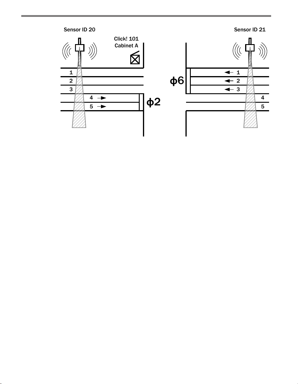
Figure 7.3 illustrates an example where the Click 101 in Cabinet A can retrieve lane-bylane volume and occupancy data from Sensor ID 20 and 21. e data from lanes 4 and 5 of
Sensor ID 20 is used to control phase 2 of the intersection, and the data from lanes 1–3 of
Sensor ID 21 is used to control phase 6. e other lanes from Sensor ID 20 and 21 can be
retrieved by Click 101 devices in cabinets at the adjacent arterial intersections.
Page 52
CHAPTER 7 CLICK 101 51
Sensor ID 21
1
2
3
4
5
Sensor ID 20
Click! 101
Cabinet A
1
2
3
4
5
ф
2
ф
6
Figure 7.3 – The Click 101 Collects from Multiple Sensors
More sensors can be used to control all the phases at each intersection along an arterial or
within a city grid. Each sensor has two dierent buers for the lane-by-lane volume and
occupancy data. ere will be no loss of data on the sensor as long as each Click 101 communicates over a dierent serial port.
During its normal polling routine, the Click 101 can collect trac data from up to ten sidere units. e normal polling routine will request new lane-by-lane volume and occupancy
data every time it cycles through the list of sensors. If a sensor does not respond aer ten
cycles, the Click 101 will suspend data queries to that sensor for one minute. Aer one minute, the Click 101 will retry data queries twice. If those queries are unsuccessful, the Click
101 will suspend queries for another minute. is feature prevents unresponsive sensors
from unnecessarily slowing down the polling routine.
A Click 101 will not execute its normal polling routine if:
It is being programmed with Click Supervisor or the push-button.
It is being used for RS-232 to RS-485 conversion.
A device connected to the RS-485 bus has sent a passcode message to temporarily
suspend polling.
Lane outputs from any one of the side-re sensors can be mapped to any of the 16 digital
outputs. Mapping multiple lanes to a single output it also possible.
Physical Features
e Click 101 has 2 communication ports, 16 LEDs, 16 digital outputs and a push-button
(see Figure 7.4).
Page 53

52 CHAPTER 7 CLICK 101
Figure 7.4 – Diagram of the Click 101
Communication Ports
e back of the Click 101 features a 5-position connector that plugs into a T-bus connector
and provides DC power and half-duplex RS-485 communication to the device. e RS-485
communication port on the T-bus allows the Click 101 to serve as the polling master on a
multi-drop RS-485 bus. e sensors act as clients on the RS-485 bus, only responding to
requests from the Click 101. Any devices connected to the T-bus will also have connectivity
over the shared RS-485 lines; however, when a Click 101 is being used, it is expected that
none of the sensors or other devices on the bus will push data. is will help avoid communication message collisions on the RS-485 bus.
Note
It is recommended that the sensors not be connected to the T-bus while programming this device with Click Supervisor.
e front of the Click 101 features a DB-9 connector for RS-232 communication. is connector is used for device conguration using Click Supervisor. A straight-through cable can
be used to connect from this port to a computer.
Page 54

CHAPTER 7 CLICK 101 53
Note
After you have completed programming the device using Click Supervisor, remove
the RS-232 serial cable from the DB-9 port. This will prevent computer equipment
(like docking stations) from holding the RS-232 TD line high. If the TD line is inadvertently held high, the Click 101 will transmit on the RS-485 bus, but will not receive any
data from connected sensors.
Like many of the other Click devices, the Click 101 also acts as an RS-232 to RS-485 converter. To disable the normal polling routine and enable serial conversion, a passcode message must rst be sent over one of the ports. SmartSensor Manager automatically sends
a passcode message when a connection is made to a side-re sensor. is allows you to
congure any of the sensors on the RS-485 bus via the DB-9 connector on the front of the
Click 101. e normal polling routine will resume operation aer 10 seconds of inactivity
on the ports. SmartSensor Manager HD sends a passcode message once every few seconds
to keep the normal polling routine of the Click 101 suspended. SmartSensor Manager for
the 105 sensor only sends passcode messages on some screens, so you may run into situations where normal polling will resume while connected to a 105 sensor.
e passcode message can be one of those shown in Table 7.1:
C String Format Hex Byte Format
“X5/r” 0x58 0x35 0x0D
“Z1/r” 0x5A 0x31 0x0D
“Z2/r” 0x5A 0x32 0x0D
Table 7.1 – Passcode Messages that Enable Serial Conversion
LEDs
e Click 101 faceplate contains 16 LEDS. During normal polling, each LED lights up when
the associated digital output is active.
If normal polling is suspended and the device is powered, the PWR (red) LED will light up
and the RD (yellow) LED will activate each time data is received on a communication port.
e TD (green) LED will not activate each time data is transmitted on a communication
port. e green LED is used during normal polling to indicate that output 15 is active, and
it is also used during manual conguration to select the autobaud conguration task.
Screw Terminals
e screw terminals labeled 1–16 on the top and bottom of the Click 101 are contact closure
outputs that can be connected to a trac controller or data logger. ese digital outputs are
contact closure outputs that require a logical ground connection.
Page 55

54 CHAPTER 7 CLICK 101
e screw terminals labeled C1–C4 represent the common lines for each contact closure
output pluggable screw terminal block (see Figure 7.4):
C1 – e common terminal for digital outputs 1–4.
C2 – e common terminal for digital outputs 5–8.
C3 – e common terminal for digital outputs 9–12.
C4 – e common terminal for digital outputs 13–16.
Configuration Features
e lower section of the faceplate has a push-button labeled Mode Switch, which is used to
initiate conguration tasks. ese tasks will be discussed in the On-device Conguration
section of this chapter.
Installation
Wire the outputs of the Click 101 to a trac controller or other contact closure input. Make
sure that each bank of the four outputs shares a single common wire. Tie each bank’s common wire to either Logic Ground or the proper common connection.
Note
It is recommended that the sensors not be connected to the T-bus while programming this device with Click Supervisor.
On-device Configuration
e Click 101 can be partially congured using the Mode Switch push-button. is pushbutton cycles through two device conguration tasks: autobaud conguration and reset to
factory defaults.
To select a task, hold the push-button down until the corresponding red or green LED
turns on. Once a conguration task has nished, the Click 101 will return to normal polling mode. During normal polling, the LEDs on the bottom row are used to signal contact
closure outputs.
e autobaud task is initiated by holding the push-button until the green LED lights up.
is task will set the polling baud rate to match that of one of the 10 possible sensor connections. All sensor connections must be at the same baud rate. e default baud rate of the
sensors and the Click 101 is 9600 bps. However, communication modems or other devices
in between the sensor and the Click 101 may dictate the baud rate.
Page 56

CHAPTER 7 CLICK 101 55
Note
You will only be able to communicate properly if the Click 101 and each sensor’s RS485 baud rate match.
To reset the module to factory defaults, hold the push-button down for 10-15 seconds until
the red LED ashes. During the reset process, the rst 12 red LEDs will light up momentarily.
Computer Configuration
You must use Click Supervisor to customize the polling parameters, output mapping and
other important settings. See Chapters 4 and 5 for instructions on how to download and
install Click Supervisor and how to connect to your device using the soware.
You will usually select the Expert driver to congure a Click 101. e Expert driver does not
modify Click 101 settings unless you save changes to the device. You should not connect
to your device using other drivers, unless you are sure that driver has been specically designed for your application. Other drivers may inadvertently overwrite the settings on your
module. Once you have nished conguring your device, save the settings to a backup le.
Aer you have made conguration changes on a driver and saved it to the Click device, the
word “current” will appear aer that driver to indicate the driver that is currently loaded
onto the device.
Note
Some settings appear on multiple drivers. Changing one of those settings on any
driver and saving them to the Click device will change that setting on all other drivers.
Expert Driver
e Expert driver allows you to see all possible settings and elds, both those available in
other drivers and those available only through this driver. e driver is divided into three
tabs—System, Contact Closures and Diagnostics—which are then subdivided further.
e System > General tab allows you to change the settings aecting the setup of the device
(see Figure 7.5 and Table 7.2).
Page 57

56 CHAPTER 7 CLICK 101
Setting Description
Module
Driver
Description
Location
Serial #
Firmware Version
Subnet ID
Device ID
Table 7.2 – Expert Driver General Tab
Figure 7.5 – Expert Driver General Tab
Allows you to enter a name and description of the device.
Names the driver you are currently working with.
Shows a description of the device being configured. This is only for
your information and does not aect the operation of the device.
Displays the location of the device being configured. This is only for
your information and does not aect the operation of the device.
Displays the serial number of your device.
Shows the version of firmware your device currently has installed. If
Click Supervisor detects a discrepancy between this version and the
most current version it currently has access to, you will be prompted
to upgrade when you connect to the device.
Shows the subnet ID number. This option is currently not available.
Gives the ID number of the device being configured, which is used
to identify the device when you are connecting to it. By default, this
number is the last five digits of the serial number, which can be found
under the About tab or on the barcode sticker on the bottom of the
device. It is recommended that you do not change this number unless
another device on your network has the same ID number.
e System > Comm tab allows you to congure how the Click device communicates (see
Figure 7.6 and Table 7.3).
Page 58

CHAPTER 7 CLICK 101 57
Figure 7.6 – Expert Driver Comm Tab
Setting Description
Baud Rate
Flow Control
Parity
Stop Bits
Data Bits
Active Port
Latency
Table 7.3 – Expert Driver Comm Tab
Allows you to change the baud rate for both the RS-485 and RS-232
communication ports.
Is used for configuring hardware handshaking. This option is currently
not available.
Allows you to set parity error checking.
Allows you to set the number of stop bits.
Shows you the number of data bits being sent. This option currently
cannot be changed.
Indicates on which port you are communicating with one of the sensors on the multi-drop RS-485 bus. When you communicate to more
than one sensor, the port may be dierent on each sensor. To change
the connection port, you will have to physically change the connection
of the communications link.
Indicates the latency between the sensor and the Click device. This
option cannot be changed.
e System > Autobaud tab allows you to congure how the device autobauds (see Figure
7.7 and Table 7.4).
Page 59

58 CHAPTER 7 CLICK 101
Setting Description
Command
Response
SmartSensor ID
Server/Client
Table 7.4 – Expert Driver Autobaud Tab
Figure 7.7 – Expert Driver Autobaud Tab
Allows you to set the command sent from the device during the
autobaud process.
Shows the response the device is expecting from the above command.
Shows the ID number of one of the sensors with which the Click
device is currently communicating. This only shows the number after
you have autobauded the Click device; when the Click device is not
communicating with a sensor, this option will display a 0.
This setting is not used by the Click 101.
e Contact Closures > Sensor tab allows you to change contact closure outputs and the
normal polling routine (see Figure 7.8 and Table 7.5).
Figure 7.8 – Expert Driver Sensor 1 Tab
Page 60
CHAPTER 7 CLICK 101 59
Setting Description
Sensor ID
Contact Closure
Outputs
Table 7.5 – Expert Driver Sensor 1 Tab
The sensor’s multi-drop communication ID.
Allows you to set the Click 101 output for lanes 1-10 of each sensor.
SmartSensor HD has 10 lanes per sensor; SmartSensor 105 only has 8
lane per sensor. Assignments made for Lanes 9 and 10 of a SmartSensor 105 unit will have no impact. Multiple lanes from one or more
sensors can also be assigned to the same output.
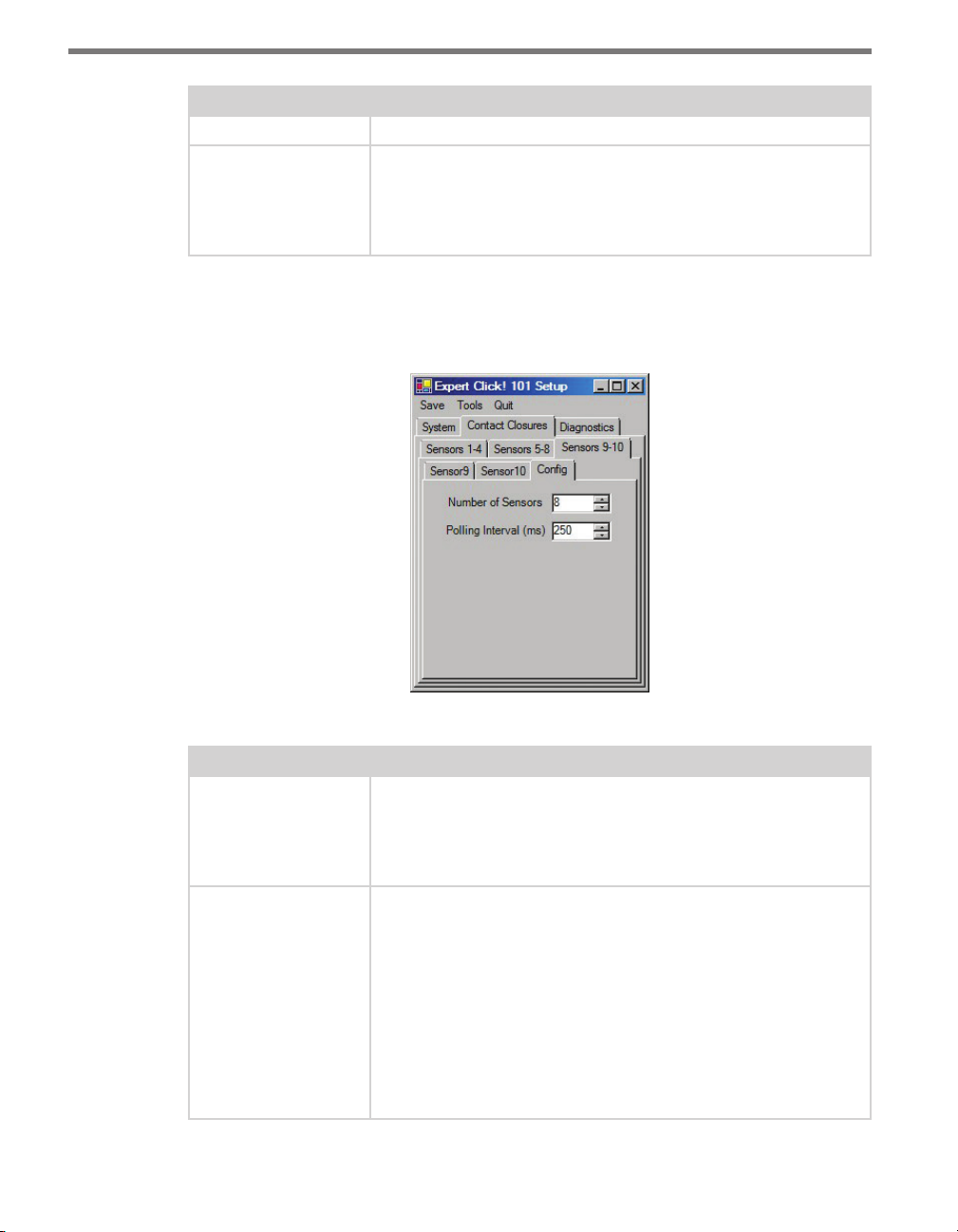
e Contact Closures > Cong tab is located under the Sensors 9-10 tab and allows you
to select the number of sensors and set the polling interval (see Figure 7.9 and Table 7.6).
Figure 7.9 – Expert Driver Config Tab
Setting Description
Number of Sensors This indicates how many of the 10 possible sensors you would like to
include in the current polling list. If you select only 1, then only sensor
1 will be polled for data. If you select 2, then only sensors 1 and 2 will
be polled for data. In other words, sensors 1–X will be polled, where X
is the value entered in this field.
Polling Interval (ms) The amount of time allotted for each sensor in the polling list to re-
spond. If a sensor responds more quickly, the Click 101 will continue to
wait until the full time interval has expired. In other words, if you poll
8 sensors with an interval of 250 ms, you will query each sensor every
2 seconds. This two seconds represents the time required to poll all
sensors on the list. This is defined as the total list poll time. The total
list poll time is variable when sensors are momentarily dropped from
the polling list. Unresponsive sensors are dropped from the poll list
for one minute. For example, if 1 of 8 devices is not responding to
requests, then the total list poll time will be 1.75 seconds (during the
cycles that the unresponsive sensor is dropped from the list).
Table 7.6 – Expert Driver Config Tab
Page 61
60 CHAPTER 7 CLICK 101
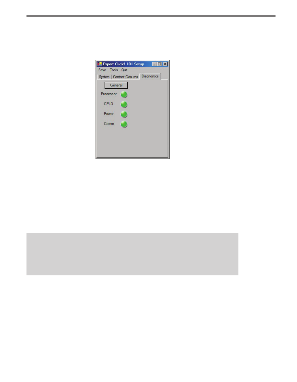
Under the Diagnostics tab, you can run diagnostics on your device (see Figure 7.10). Click
the General button to run diagnostics on the items listed below the button. If a problem is
detected, the program will display a red square next to the item in question. If no problems
are detected, a green circle will appear.
Figure 7.10 – Expert Driver Diagnostics Tab
Once you have nished, use the menu bar at the top of the screen to save your settings,
return to the Select Driver screen, and more.
e Save menu allows you to save your settings. Select Save to File to save your set-
tings to a le. Selecting this will open a directory box, allowing you to name your
settings le. is le will always be saved in the Wavetronix folder created when you
installed Click Supervisor, under Wavetronix > ClickHome > Drivers > 101 > User. You
can also select Save to Device to save your settings to your Click 101.
Note
If you do not save your settings to your Click 101, they will be lost the next time you
power the device down.
e To o l s menu contains ve options for working with your device. Reset > System
power cycles your device, while Reset > Factory Default restores your device to the
settings with which it was shipped. Restore will restore the driver to the settings currently saved on the Click 101, erasing any unsaved changes. Upgrade can be used to
manually upgrade to the most current rmware for your device. Hex View changes the
view of certain settings in the driver to hexadecimal.
Clicking the Quit menu exits the driver and returns you to the Click Supervisor main
page.
Page 62

Click 104 —
4-channel DIN Rail Contact Closure 8
In this chapter
Physical Features
Installation
Configuration
Rotary Switch
Front Panel Menu
Click Supervisor
8
e Click 104 is a 4-channel contact closure module for use with sensors that use Z4 protocol: HD, Advance and Matrix. It mounts on a DIN rail for power and communication.
Figure 8.1 – The Click 104
Page 63

62 CHAPTER 4 CLICK 104
Physical Features
e Click 104 has the following physical features.
T-Bus
Connector
TOP
RS-232 Connector
FRONT
RS-232
+DC
-DC
+485
-485
GND
Bus 2
Control
Bus 1
Data
Click
104
Contact
Closures
3-4 1-2
Bus 1
Data
LEDs
RS-485
Mode
Switch
Rotary
Switch
Outputs 1-2 Connector
Outputs 3-4 Connector
LED Indicators
RS-485
Connector
Mode Switch
Rotary Switch
Figure 8.2 – Diagram of Click 104
Communication Ports
e Click 104 has two independent serial communications buses. Bus 1, also referred to
as the data bus, should be used to report vehicle data; its associated communication ports
consist of two RJ-11 jacks, for RS-485, on the faceplate and one screw terminal, for RS-232,
on the top of the device.
Bus 2, also referred to as the control bus, should be used for conguration. Its associated
communication port is the a 5-position connector, located on the back of the Click 104, that
plugs into a T-bus connector and provides power and RS-485 communication to the device.
It also passes RS-485 communication from the Click 104 to all other devices on the T-bus.
Contact Closure Outputs
e contact closure outputs should be wired to a controller, data logger or BIU (Bus Interface Unit) using the pluggable screw terminals on the bottom of the Click 104. ere
are two screw terminal blocks; the one closer to the faceplate has outputs 1 and 2, and the
farther one has outputs 3 and 4. Each output consists of two terminals, one + and one –.
e screw terminal connectors can also be unplugged from the Click 104 allowing you to
Page 64
CHAPTER 4 CLICK 104 63
pre-wire the Click 104 before nal installation.
Rotary Switch
On the faceplate of the device is a rotary switch, numbered 0–9. is switch, which can be
twisted by inserting a small screwdriver into the arrow slot, is used to congure channels.
Mode Switch
e faceplate of the Click 104 features a push-button labeled Mode Switch, which is used to
cycle through and select menu and conguration options.
LEDs
e faceplate of the Click 104 has three banks of LEDs. e top bank is used for detection
indication, the second bank menu indication, and the third for menu indication as well as
operation states.
Channel
1 2 3 4
Menu
PWR OK TD RD
Figure 8.3 – Click 104 LEDs
e Channel LEDs are detection indicators; they consist of four red LEDs numbered 1–4,
each representing a channel (see Figure 8.3). An illuminated LED indicates that the associated contact is being closed (this can mean either a vehicle detection or fail-safe mode,
which will be discussed later in this chapter). ese indicators are dedicated to detection
and have no other display purposes.
e menu indicator LEDs include two rows of LEDs (see Figure 8.3). e lower row contains Level 1 indicators, while the upper row contains Level 2 indicators. Each level consists
of four LEDs numbered 1–4 (le to right). Level 1 LEDs (the multicolored row) display
which menu item is active. ese Level 1 LEDs are dual-purpose, each indicating both
menu selection as well as a normal operation state when not in Menu mode. e normal
operation state functions include:
Red (PWR) – Indicates the presence of power to the device.
Blue (OK) – Indicates proper system operation; it extinguishes during fail-safe mode.
Green (TD) – Indicates serial communication transmit data (from the Click 104) on
either bus 1 (data) or bus 2 (control).
Yellow (RD) – Indicates serial communication receive data (to the Click 104) on either
Page 65

64 CHAPTER 4 CLICK 104
bus 1 (data) or bus 2 (control).
Level 2 LEDs display conguration options for the menu items selected via the level 1 LEDs.
All level 2 LEDs are red. ese LEDs are dedicated to menu operation, and are extinguished
when the menu is not active.
Installation
1 Mount the Click 104 on a DIN rail over a T-bus connector. is connects the device’s
control bus (bus 2) to the installation’s shared communication bus; you can connect
your computer to another device on this shared bus, such as the Click 305 USB converter, to access the Click 104 to congure it using Click Supervisor. Mounting the
Click 104 on the T-bus also connects it to the power source.
2 Send detection data to the data bus (bus 1) in one of two ways. If you’re using a Smart-
Sensor Advance or Matrix, and therefore a Click 222 or 223, connect it to the Click 104
by connecting jumper cables from the RJ-11 jacks on the faceplate of the Click 222 or
223 to the RJ-11 jacks on the faceplate of the Click 104.
If you’re using a SmartSensor HD, rst set the sensor to push data on the RS-232 port.
en connect wires between the TD and RD screw terminals on the protected side of
the Click 200 to the TD and RD screw terminals on the Click 104.
3 If needed, daisy-chain multiple Click 104 devices together by utilizing both RJ-11 jacks
on each device’s faceplate.
Contact Closure Outputs
Part of installing the device is wiring its contact closure outputs to the trac controller
(or data logger or other device). It’s recommended, however, that you not do this until the
device is done being congured, to avoid sending any incorrect contact closures to the
controller
ere are four contact closure outputs, for the four channels the Click 104 can handle. Each
output has two screw terminals, one + and one –. e + terminals are for data, while the
– are ground, or common. Each – terminal is isolated from all the other grounds; if your
installation requires a common ground for each contact closure output, you’ll need to tie
together the wires from those four terminals yourself.
Fail-safe Mode
e Click 104 receives datagrams from the connected SmartSensor. ese datagrams must
be mapped to device outputs, as will be discussed later in this chapter. If the Click 104 does
not receive a datagram describing the device’s channels for ten seconds, the device will enter
fail-safe mode. In fail-safe mode, all outputs will assert a detection condition, and will continue to do so until the device receives a datagram that updates the state of its congured
channels. See the Click Supervisor section of this chapter for more information on how to
Page 66

CHAPTER 4 CLICK 104 65
change the amount of time that must elapse without the device receiving a pertinent datagram before the device enters fail-safe mode.
Configuration
e Click 104 can be congured in three ways: the rotary switch (which can only change
one parameter), the front panel menu, and Click Supervisor.
ese three conguration methods can congure dierent sets of parameters; some of these
parameters can be set using multiple conguration methods, and some of them can only be
set using one particular method. Table 8.1 lists how each parameter may be accessed and
congured.
Rotary Switch Front Panel Menu Click Supervisor
Baud Rate No Yes Ye s
Channel Input Map Yes Yes Yes
Autobaud No Yes No
Reset to Default No Yes Ye s
Description No No Yes
Location No No Yes
Device ID No No Yes
Fail-safe Settings No No Yes
To use this
configuration option:
Table 8.1 – Click 104 Configuration Options
Hardware mode Software mode Software mode
Configuration Modes
e nal row on the table refers to conguration modes. Hardware mode means a particular parameter is set by the rotary switch; Soware mode means that parameter is set by
either the front panel menu or Click Supervisor. However, this is only applicable for channel
input mapping, since that is the only parameter that can be set by the rotary switch.
e position of the rotary switch determines whether the device is in Hardware or Soware
mode:
If the switch is set to 0, the device is in Soware mode. is means that all parameters
are set by the front panel menu or Click Supervisor.
If the switch is set to any other number, the device is in Hardware mode, meaning that
the channel input mapping is set by the rotary switch. If this is set, you will not be able
to change the channel input mapping any other way; in Click Supervisor the option
will be grayed out, and the front panel menu will only allow to view, not change, this
setting. However, even when the rotary switch is set in Hardware mode, you will still be
Page 67

66 CHAPTER 4 CLICK 104
able to congure all other parameters (besides channel input mapping) using the front
panel menu and Click Supervisor.
Note
If any non-switch setting—that is, those that aren’t set by the rotary switch—has
been set using both the front panel menu and Click Supervisor, whichever configuration was set most recently will take precedence.
Rotary Switch
e rotary switch is located on the lower part of the faceplate and can be used to change
the channel input mapping. Remember that if you use this switch to set the channel input
mapping, you won’t be able to use the soware or the front panel menu to change this
particular parameter (although you will still be able to use them to change other parameters).
Channel input mapping is the process of telling the device which incoming data channels
should be mapped to which outgoing channels. As mentioned earlier, the Click 104 receives
serial datagrams from a sensor to which it is connected. ese datagrams can contain many
channels of detection data. Because the devices have fewer output channels than there are
possible input datagram channels received from the sensor, you must use the channel input
map to map the desired inputs to outputs. e Click 104 has four output channels; if you
need more than this, you’ll need to use multiple devices daisy-chained together.
As shown in the table below, the outputs are mapped sequentially—that is, they can only
be mapped in numerically ordered groups of four (1–4, 5–8, etc.). If you set the switch to
3, for 9–12, then input 9 would be mapped to output 1, input 10 would be mapped to output 2, input 11 would be mapped to output 3, and input 12 would be mapped to output 4.
Switch Channels
0 Software mode
1 1–4
2 5–8
3 9–12
4 13–16
5 17–20
6 21–24
7 25–28
8 29–32
Page 68

CHAPTER 4 CLICK 104 67
9 33–36
Table 8.2 – Click 104 Rotary Switch Channel Input Map Settings
To set the switch, insert a small screwdriver into the slot and twist until the arrow is pointed
at the desired number.
Front Panel Menu
e front panel of the device features a push-button and three banks of LEDs for on-device
conguration and monitoring. e rst bank of LEDs, labeled Channel, displays the state of
the contact closure outputs and is described in the Physical Features section.
e two lower banks of LEDs, labeled Menu, and the push-button, labeled Mode Switch,
are used for navigating through Menu mode. is section will cover how to use the menu
to congure the Click 104.
e lower bank of LEDs will be referred to as Level 1 and is used in selecting menu options.
e upper bank will be referred to as Level 2 and is used in conguring the menu options.
Level 2 LEDs only light up when a menu selection is made using the Level 1 LEDs.
1 2 3 4
Menu
Level 2
Level 1
Mode Switch
Figure 8.4 – Menu Indicator LEDs and Mode Switch
PWR
OK TD RD
Note
The LEDs in the lower bank also function as activity/status indicators. These functions, outlined in the Physical Features section of this chapter, are only executed
when the device is not in Menu mode. In this case, the upper bank of LEDs (Level 2)
remains o.
Navigating through the Menu
e mode switch push-button is used to enter Menu mode. To use the menu:
1 Press and hold the mode switch to enter Menu mode. e Level 1 LEDs will start to
Page 69
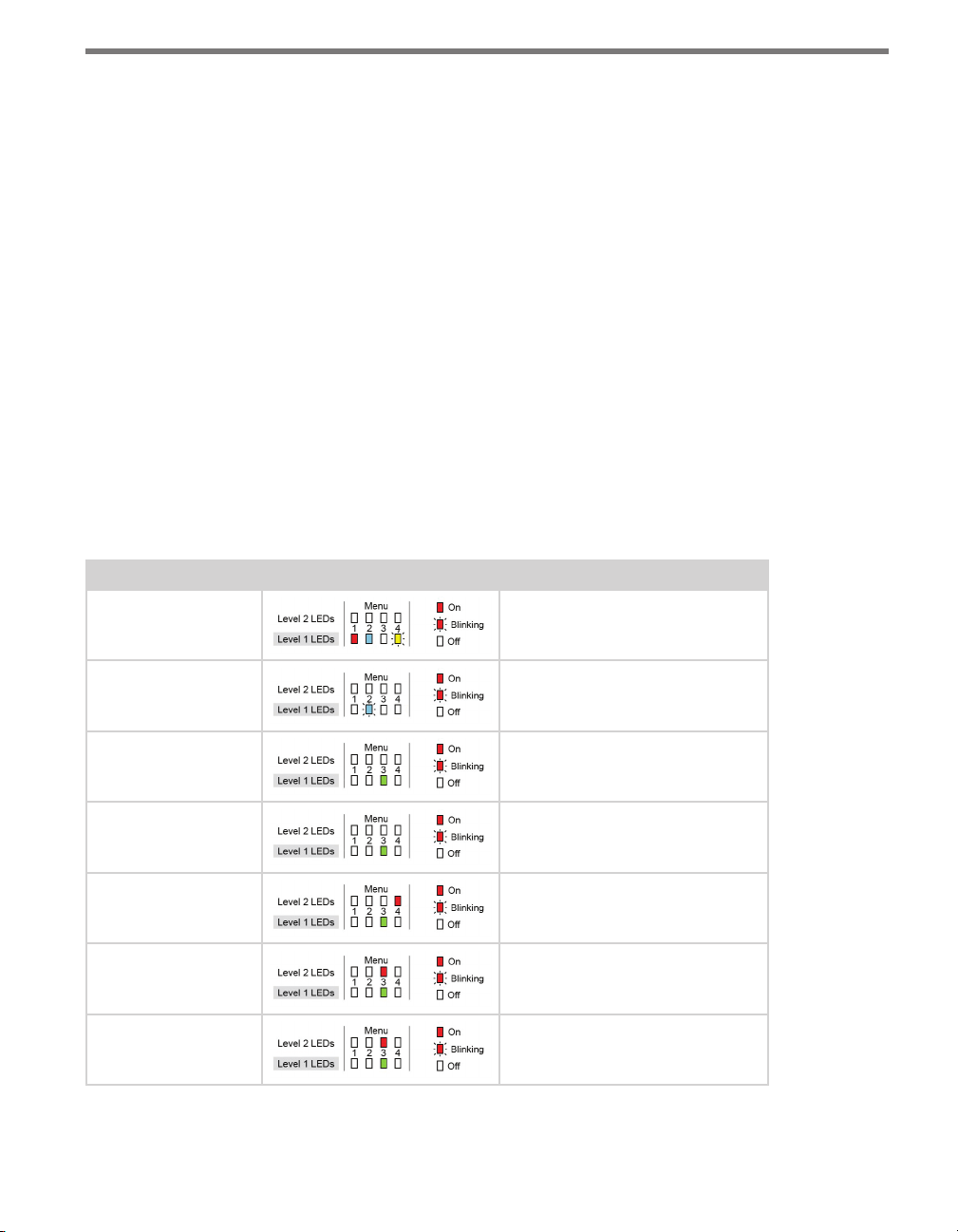
68 CHAPTER 4 CLICK 104
light up to indicate that the device is cycling through all menu options (specics on
these menu options, and which LEDs and LED combinations represent them, will be
covered later in this section).
2 Release the mode switch when you reach the desired menu option. (Pressing and hold-
ing again will resume cycling through menu options.)
3 Quickly press and release the mode switch to select the current menu option. Once it’s
selected, the Level 2 LEDs will start to let you congure the options for the selected
menu option.
4 Press and hold the mode switch to cycle through the submenu. e Level 2 LEDs will
light to indicate that the device is cycling though all conguration options (specics on
these conguration options, and which LEDs and LED combinations represent them,
will be covered later in this section).
5 Release the mode switch once the desired conguration option is reached.
6 Quickly press and release the mode switch to select the current conguration option.
e device will exit Menu mode, and either the selected function will run or the selected conguration will be set and saved to the device.
For example, the following table illustrates an example of how the mode switch and menu
indicator LEDs are used in conguring the Click 104—in this case, how to autobaud bus 2.
Mode Switch Action Display State
None Normal operation
Press and hold Channel map menu option displayed
Continue holding Autobaud menu option displayed
Release Autobaud menu option displayed
Press and release Autobaud menu selected and first
configuration parameter displayed
(bus 1 autobaud)
Press and hold Second configuration parameter
displayed (bus 2 autobaud)
Release Second configuration parameter
displayed
Page 70
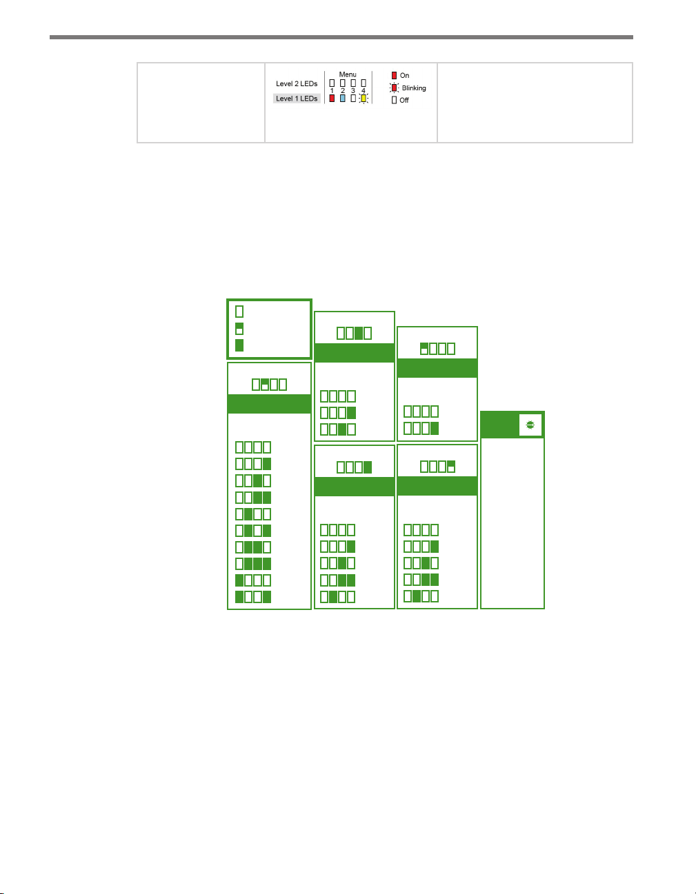
CHAPTER 4 CLICK 104 69
Menu Operation
•
Press and release Configuration parameter selected;
autobaud commences (will show
intermediate LED states); autobaud finishes and normal operation
resumes
Table 8.3 – Menu Operation Example
Inactivity of one minute on the mode switch will exit menu mode.
Front Panel Menu Options
e following gure documents the menu and conguration options available from the
front panel menu. is label is also printed on the side of the device.
e menu options are displayed on the Level 1 LEDs (multicolored) and the conguration
parameters are displayed on the Level 2 LEDs (all red).
= LED O
= LED Flashing
= LED On
R B G Y
Input Mapping
Menu LEDs
1 2 3 4
Cancel
1-4
5-8
9-12
13-16
17-20
21-24
25-28
29-32
33-36
R B G Y
Autobaud
Menu LEDs
1 2 3 4
Cancel
Bus 1
Bus 2
R B G Y
Bus 1 Baud Rate
Menu LEDs
1 2 3 4
Cancel
9600
19200
38400
57600
PUSH and HOLD Mode Switch to
cycle through menus and options.
R B G Y
Reset to Default
Menu LEDs
1 2 3 4
R B G Y
Bus 2 Baud Rate
Menu LEDs
1 2 3 4
Cancel
Reset
Cancel
9600
19200
38400
57600
• PUSH and
RELEASE
Mode Switch
to make
selections.
• 1 minute of
inactivity exits
menu.
Rotary
Switch
= SW0
= 1-4
1
= 5-8
2
= 9-12
3
= 13-16
4
= 17-20
5
= 21-24
6
= 25-28
7
= 29-32
8
= 33-36
9
8
7
9
6
0
5
1
4
2
3
Figure 8.5 – Front Panel Menu Label
Channel Input Map
e rst conguration parameter that comes up when you’re cycling through the front
panel menu is the channel input map. To select this parameter, release the push-button
when the blue LED ashes.
Page 71
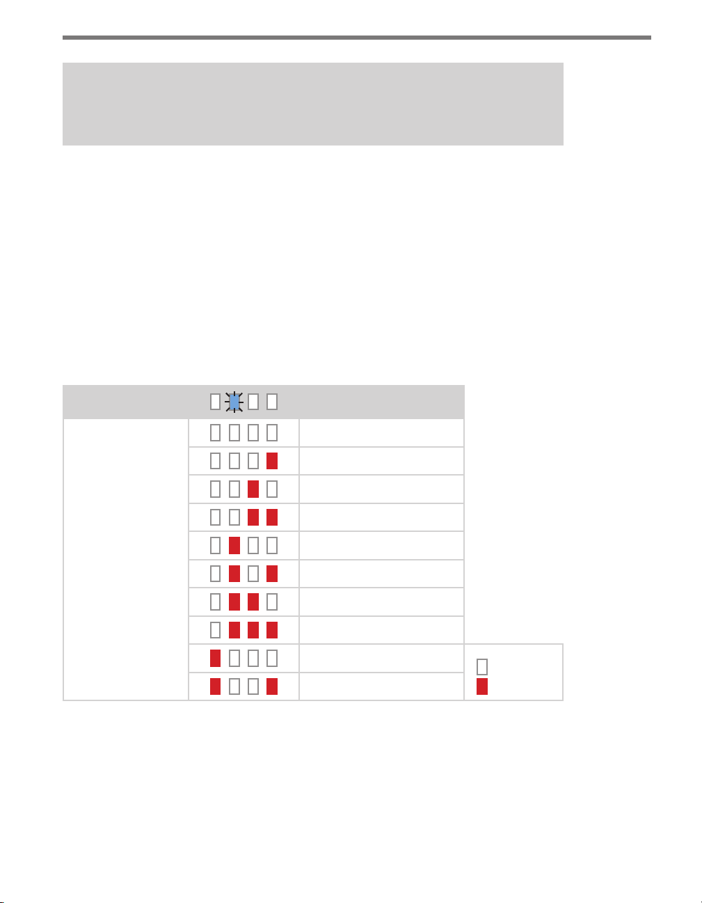
70 CHAPTER 4 CLICK 104
Note
This parameter can also be changed using the rotary switch or Click Supervisor.
As mentioned earlier, the Click 104 devices receive serial datagrams from a SmartSensor.
ese datagrams can contain many channels of detection data.
Because the devices have fewer output channels than there are possible input datagram channels received from the sensor, you must use the channel input map to map the desired inputs
to outputs. e Click 104 has four outputs and therefore must be mapped to four inputs; if
you need more than four channels, you’ll need to use multiple devices daisy-chained together.
As shown in the table below, the outputs are mapped sequentially—that is, they can only be
mapped in numerically ordered groups of four (1–4, 5–8, etc.). If you set the switch to 3, for
9–12, then input 9 would be mapped to output 1, input 10 would be mapped to output 2,
input 11 would be mapped to output 3, and input 12 would be mapped to output 4.
Level 1 LEDs
Level 2 LEDs
Table 8.4 – Click 104 Front Panel Menu Channel Input Map Settings
Input Mapping
Cancel and exit menu
Channels 1–4
Channels 5–8
Channels 9–12
Channels 13–16
Channels 17–20
Channels 21–24
Channels 25–28
Channels 29–32
Channels 33–36
LED o
LED on
See the earlier Navigating through the Menu and the Menu Operation Example sections for
how to congure this parameter.
Because this parameter can also be set by the rotary switch, you may need to ensure that the
switch is set to 0; if it’s not, the front panel menu will be able to display but not change the
channel input mapping.
Page 72
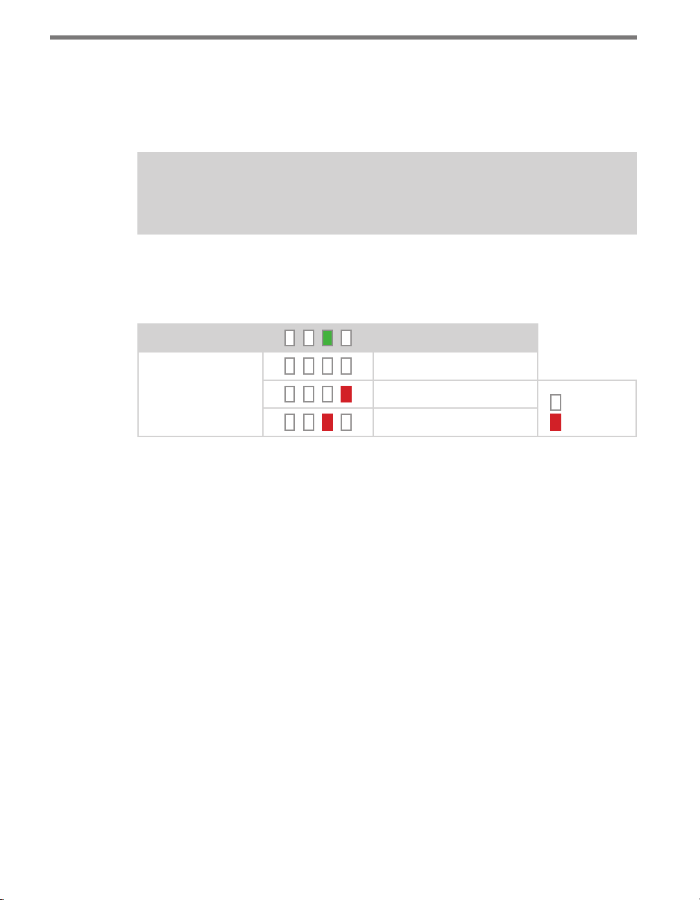
CHAPTER 4 CLICK 104 71
Autobaud
e second option that comes up when you’re cycling through the front panel menu is
the autobaud function. To select this option, release the push-button when the green LED
comes on solid.
Note
The autobaud function can only be accessed here, on the front panel menu.
is function initiates an autobaud on the communication buses (you will select which bus
to autobaud on the Level 2 LEDs). An autobaud will stop data reporting on the selected port
and attempt to communicate with the SmartSensor at all supported baud rates.
Level 1 LEDs
Level 2 LEDs
Table 8.5 – Front Panel Menu Autobaud Settings
Autobaud
Cancel and exit menu
Autobaud on bus 1
Autobaud on bus 2
LED o
LED on
See the earlier Navigating through the Menu and the Menu Operation Example sections for
how to congure this parameter.
As each baud rate is attempted, the Level 2 LEDs will sequence with a single LED illuminated from LED 1–4.
If the Click 104 is successful in communicating with a SmartSensor, it will display the baud
rate found, using the same Level 2 LED pattern used in selecting the baud rate (covered in
the Baud Rate section of this chapter and Table 8.6). Aer a short time of displaying the autobaud results, the menu will return to normal operation with the baud rate setting updated
(and stored) to the baud rate detected during the autobaud process.
If the autobaud fails, all four Level 2 LEDs will light up for a few seconds, and then the
menu will return to normal operation with the baud rate setting remaining unchanged.
Baud Rate (Bus 1 and 2)
e next two conguration parameters that come up in the front panel menu allow you to
manually set the baud rate of the two communication buses. Bus 1 comes up rst, with the
yellow LED coming on solid, then bus 2, with the yellow LED ashing.
Page 73
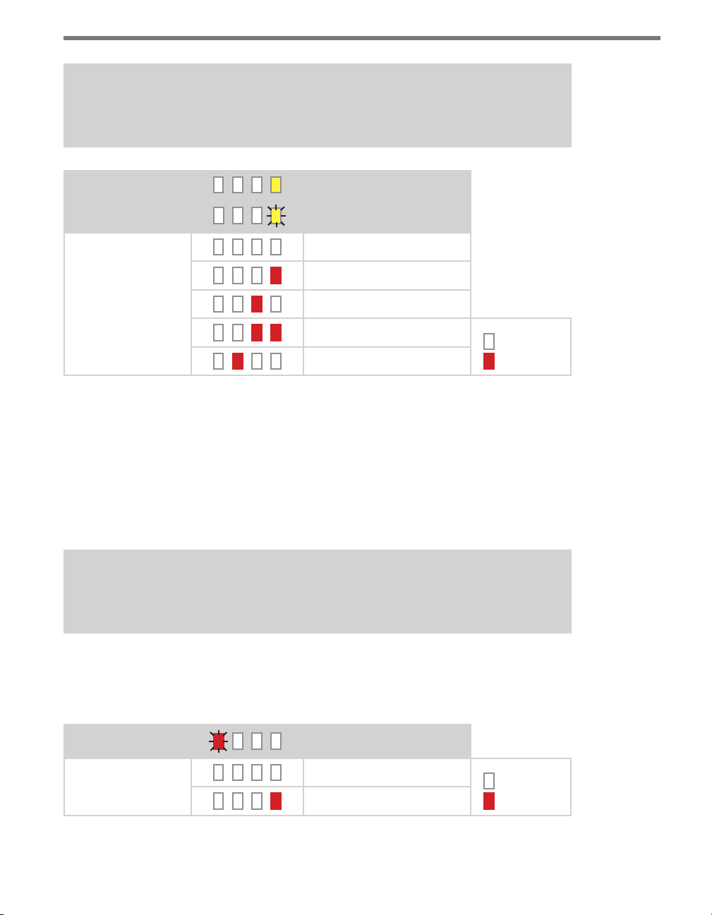
72 CHAPTER 4 CLICK 104
Note
This parameter can also be changed using Click Supervisor.
Baud rate for bus 1
Level 1 LEDs
Level 2 LEDs
Table 8.6 – Front Panel Menu Baud Rate Settings
Baud rate for bus 2
Cancel and exit menu
9600 bps (default)
19200 bps
38400 bps
57600 bps
LED o
LED on
See the earlier Navigating through the Menu and the Menu Operation Example sections for
how to congure this parameter.
Reset to Default Settings
e nal option that comes up in the menu is Reset to Default Settings. To select this function, release the mode switch when the red LED starts ashing.
Note
Resetting to default settings can also be done using Click Supervisor.
is function will restore all conguration settings to factory defaults, even those parameters not congured using the front panel menu: baud rate, channel input map, description
eld, location eld, and device ID.
Level 1 LEDs
Level 2 LEDs
Table 8.7 – Front Panel Menu Reset to Default Settings
Reset to Default Settings
Cancel and exit menu
Reset to default settings
LED o
LED on
Page 74

CHAPTER 4 CLICK 104 73
See the earlier Navigating through the Menu and the Menu Operation Example sections for
how to view this parameter.
Aer the Click 104 has reset to factory defaults, it will check the rotary switch; if it is set
to any option besides 0, that channel input mapping will be applied. If resetting to factory
defaults doesn’t reset the channel input mapping, check the rotary switch to see if it’s aecting this setting.
Click Supervisor
Click Supervisor is the only way to congure non-data path type parameters such as the
description, location, and device ID. See Chapters 4 and 5 of this document for instructions
on how to download and install Click Supervisor and how to connect to your device using
the soware.
Note
Some of the parameters mentioned below can only be configured in Click Supervisor.
Others can be configured by the front panel menu and/or the rotary switch. If the rotary switch has been used to configure the channel input mapping, that parameter is
considered to be in Hardware mode; it will be grayed out in Click Supervisor, meaning
you can view but not change the setting. If you would like to set it using Click Supervisor, you will have to turn the rotary switch to 0.
e Click 104 can be congured using the Expert driver (see Figure 8.6).
Figure 8.6 – Selecting a Driver
Aer you have made conguration changes on the driver and saved it to the Click device, the
word “current” will appear aer it to indicate the driver is currently loaded onto the device.
Page 75

74 CHAPTER 4 CLICK 104
e Backups option can be used to read congurations that have previously been saved to
le. See Chapter 5 for more information.
Expert Driver
e Expert driver contains two tabs, System and Diagnostics; the System tab is then subdivided further.
e System > General tab lets you change general information about your device. e tab
has the following parameters (see Figure 8.7 and Table 8.8):
Figure 8.7 – Expert Driver General Tab
Note
These parameters can only be configured using Click Supervisor.
Setting Description
Module
Driver
Description
Location
Serial Number
Allows you to enter a name and description of the device.
Names the driver you are currently working with.
Shows a description of the device being configured. This is only for
your information and does not aect the operation of the device.
Displays the location of the device being configured. This is only for
your information and does not aect the operation of the device.
Displays the serial number of your device. This information cannot be
changed.
Page 76
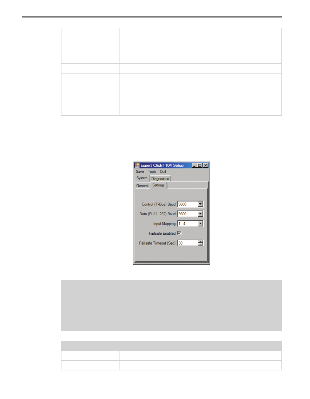
CHAPTER 4 CLICK 104 75
Firmware Version
Subnet ID
Device ID
Table 8.8 – Expert Driver General Tab
Shows the version of firmware your device currently has installed. If
Click Supervisor detects a discrepancy between this version and the
most current version it currently has access to, you will be prompted
to upgrade when you connect to the device. This information cannot
be changed.
Shows the subnet ID number. This option is currently not available.
Gives the ID number of the device being configured, which is used
to identify the device when you are connecting to it. By default, this
number is the last five digits of the serial number, which can be found
under the About tab or on the barcode sticker on the bottom of the
device. It is recommended that you do not change this number unless
another device on your network has the same ID number.
e System > Settings tab lets you congure and view many of the parameters that are also
available elsewhere on the device (see Table 8.1 earlier in this chapter for more information). e tab has the following parameters (see Figure 8.8 and Table 8.9):
Figure 8.8 – Expert Driver Settings Tab
Note
These parameters can also be configured using the front panel menu. Also, channel input mapping can be set using the rotary switch; if the rotary switch is set to
anything but 0, the input mapping drop-down will appear grayed out on this screen.
Setting Description
Control (T-Bus) Baud
Data (RJ11 _232) Baud
Lets you change the baud rate, in bps, of the control bus (bus 2).
Lets you change the baud rate, in bps, of the data bus (bus 1).
Page 77

76 CHAPTER 4 CLICK 104
Input Mapping
Failsafe Enabled
Failsafe Timeout
(Sec)
Table 8.9 – Expert Driver Settings Tab
Lets you assign input datagram channels received from the sensor
to the two or four output channels on the device. The outputs are
mapped sequentially—that is, they can only be mapped in numerically
ordered groups of four. See Input Mapping in either the Rotary Switch
or Front Panel Menu sections in this chapter for more information.
Turns on and o fail-safe mode. For more information on what this
mode is, see the Fail-safe Mode section earlier in this chapter.
Lets you select what length of time, in seconds, the device can go
without receiving datagrams describing the device’s channels before
it goes into fail-safe mode. The default is 10 seconds.
Under the Diagnostics tab, you can run diagnostics on your device (see Figure 8.9).
Figure 8.9 – Expert Driver Diagnostics Tab
Click the General button to run diagnostics on the items listed below the button. If a problem is detected, the program will display a red square next to the item in question. If no
problems are detected, a green circle will appear.
Click Failsafe Status to check whether any of the channels are in fail-safe mode. If a fail-safe
condition is detected, a red square will be displayed below the button. If no problems are
detected, a green circle will appear.
Once you have nished, use the menu bar at the top of the screen to save your settings,
return to the Select Driver screen, and more.
e Save menu allows you to save your settings. Select Save to File to save your settings
to a le. Selecting this will open a directory box, allowing you to name your settings
le. is le will always be saved in the Wavetronix folder created when you installed
Click Supervisor, under Wavetronix > ClickHome > Drivers > 104 > User. You can also
select Save to Device to save your settings to your Click 104.
Page 78

CHAPTER 4 CLICK 104 77
Note
If you do not save your settings to your Click 104, they will be lost the next time you
power the device down.
e To o l s menu contains ve options for working with your device. Reset > System
power cycles your device, while Reset > Factory Default restores your device to the
settings with which it was shipped. Restore will restore the driver to the settings currently saved on the Click 104, erasing any unsaved changes. Upgrade can be used to
manually upgrade to the most current rmware for your device. Hex View changes the
view of certain settings in the driver to hexadecimal.
Clicking the Quit menu exits the driver and returns you to the Click Supervisor main
page.
Once you have nished, click Save on the menu bar to save your settings.
Page 79

Page 80

Click 110 —
4-channel Contact Closure Eurocard 9
In this chapter
Physical Features
Installation and Wiring
Operation
Configuration
9
e Click 110 is used to report vehicle data to a MIDAS outstation when used with Wavetronix SmartSensors. is card plugs directly into an outstation and reports four channels
of detection. Because the Click 110 has two independent serial buses, it can be congured
without interfering with data reporting.
Figure 9.1 – The Click 110
Page 81
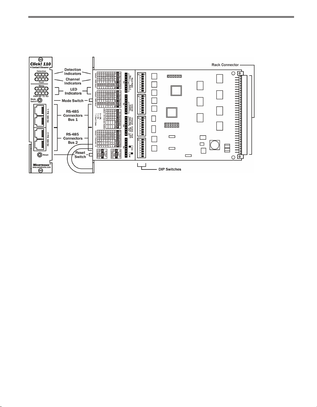
80 CHAPTER 9 CLICK 110
Physical Features
e following sections describe the physical features of the Click 110 card.
Figure 9.2 – Diagram of the Click 110
Communication Ports
e Click 110 contains two independent serial communications ports. Each port is made
up of two RJ-11 connectors, which make it simple to daisy-chain multiple Click 110 cards
together and create a RS-485 bus. e two RJ-11 RS-485 data buses can be connected to a
SmartSensor through a Click 200 surge protection module, or through a serial data converter.
Typically, one bus is used to report vehicle data, and the other is used for conguration. As
both buses are identical it does not matter which is used for data or conguration. Alternatively, a single bus could be used for both data and conguration, but data reporting would
be temporarily halted during conguration. During this time, the Click 110 will enter failsafe mode if vehicle data is not reported for ten seconds.
LEDs
e faceplate of the Click 110 has four banks of LEDs. e top bank is used for detection indication, the second bank for fault indication, the third for menu indication, and the fourth
for menu indication as well as operation states.
Page 82

CHAPTER 9 CLICK 110 81
Detection
1 2 3 4
Fault
Menu
1 2 3 4
PWR MF TD RD
Figure 9.3 – Click 110 LEDs
e detection indicator LEDs consist of four red LEDs numbered 1–4, each representing
a channel (see Figure 9.3). An illuminated LED indicates the presence of a vehicle. ese
indicators are dedicated to detection and have no other display purposes.
e fault indicator LEDs consist of four dual-color (green / yellow) LEDs numbered 1–4,
each representing the channel with the corresponding number (see Figure 9.3).
Illuminated green LED – Indicates a no-fault condition.
Illuminated yellow LED – Indicates a fault condition which has existed for less than
one minute.
Extinguished LED – Indicates a fault condition which has existed for more than one
minute.
e menu indicator LEDs include two rows of LEDs (see Figure 9.3). e lower row contains Level 1 indicators, while the upper row contains Level 2 indicators. Each level consists
of four LEDs numbered 1–4 (le to right). Level 1 LEDs display which menu is active. ese
Level 1 LEDs are dual-purpose, each indicating both menu selection as well as a normal
operation state when not in Menu mode. e normal operation state functions include:
Red (PWR) – Indicates the presence of power to the device.
Blue (MF) – Illuminates when the master fault output is in the no-fault condition. e
LED is extinguished in the fault condition.
Green (TD) – Indicates serial communication transmit data (from the Click 110) on
either RS-485 bus 1 or RS-485 bus 2.
Yellow (RD) – Indicates serial communication receive data (to the Click 110) on either
RS-485 bus 1 or RS-485 bus 2.
Level 2 LEDs display conguration options. All level 2 LEDs are red. ese LEDs are dedicated to menu operation, and are extinguished when the menu is not active.
Page 83

82 CHAPTER 9 CLICK 110
Push-buttons
e faceplate of the Click 110 features two push-buttons. e upper push-button, labeled
Mode Switch, is used to cycle through and select menu and conguration options.
e lower push-button, labeled Reset, will reboot the Click 110. e Click 110 can be rebooted in any of three ways: via the reset switch, from the outstation via the 64 way DIN
41612, or by power cycling the device. A reboot is the only way to clear a latched fault condition. To reboot using the reset switch, simply press and release the push-button.
DIP Switches
Just behind the faceplate of the Click 110, on the circuit board, is a set of DIP switches.
ese switches are used to congure the Click 110 in Hardware mode. All settings, with
the exception of Outstation mode and disabling fault latching, are also congurable via
Soware mode (front panel menu, or Click Supervisor). See the DIP Switches section of
this chapter for more information.
Installation and Wiring
Use the following steps to install and wire Click 110 devices:
1 If you’re using hardware conguration, set all DIP switches before installing Click 110
devices (this will be covered in the DIP Switches section of this chapter).
2 Insert the cards into the rack.
3 Daisy-chain together all the cards you intend to use in your installation, using short
RJ-11 jumper cables.
4 Connect the rst Click 110 card to the SmartSensor via a surge protector, such as the
Click 200, 222, or 223, and a 60" RJ-11 patch cord.
For your information, this guide includes the pinout for the 64-pin backplane connector
on the the back of the Click 110. However, the pins behave dierently depending on which
Outstation mode the device is set to, Peek or Siemens (for more on Outstation mode, see
the DIP Switches section of this chapter); the dierences all relate to the fault outputs and
whether they are normally opened or normally closed.
For this reason, there are two pinout tables on the following pages. e rst is the pinout
when the Click 110 is set to Peek; the second is when it’s set to Siemens.
Note
The pins that change between the two tables will be highlighted in light gray for ease
of comparison.
Page 84

CHAPTER 9 CLICK 110 83
Description Pin
Channel 1 fault, normally closed B1
Channel 1 common B2
Channel 1 fault common B3
Master fault, normally closed B4
No connection B5
No connection B6
No connection B7
Channel 2, normally closed B8
No connection B9
Channel 2, normally open B10
No connection B11
No connection B12
No connection B13
Chassis ground B14
Channel 3 fault, normally closed B15
Channel 3 common B16
Channel 3 fault common B17
No connection B18
No connection B19
No connection B20
No connection B21
Channel 4, normally closed B22
No connection B23
Channel 4, normally open B24
No connection B25
No connection B26
No connection B27
No connection B28
No connection B29
+DC (12–24 VDC) B30
No connection B31
-DC (common) B32
Pin Description
A1
A1 Channel 1, normally closed
A2 No connection
A3 Channel 1, normally open
A4 No connection
A5 No connection
A6 No connection
A7 Master fault, normally open
A8 Channel 2 fault, normally closed
A9 Channel 2 common
A10 Channel 2 fault common
A11 Master fault common
A12 No connection
A13 No connection
A14 No connection
A15 Channel 3, normally closed
A16 No connection
A17 Channel 3, normally open
A18 No connection
A19 No connection
A20 No connection
A21 No connection
A22 Channel 4 fault, normally closed
A23 Channel 4 common
A24 Channel 4 fault common
A25 No connection
A26 No connection
A27 No connection
A28 No connection
A29 Reset
A30 No connection
A31 No connection
A32 No connection
Figure 9.4 – Click 110 Pinout with Peek Outstation
Page 85

84 CHAPTER 9 CLICK 110
Description Pin
Channel 1 fault, normally open B1
Channel 1 common B2
Channel 1 fault common B3
Master fault, normally open B4
No connection B5
No connection B6
No connection B7
Channel 2, normally closed B8
No connection B9
Channel 2, normally open B10
No connection B11
No connection B12
No connection B13
Chassis ground B14
Channel 3 fault, normally open B15
Channel 3 common B16
Channel 3 fault common B17
No connection B18
No connection B19
No connection B20
No connection B21
Channel 4, normally closed B22
No connection B23
Channel 4, normally open B24
No connection B25
No connection B26
No connection B27
No connection B28
No connection B29
+DC (12–24 VDC) B30
No connection B31
-DC (common) B32
Pin Description
A1
A1 Channel 1, normally closed
A2 No connection
A3 Channel 1, normally open
A4 No connection
A5 No connection
A6 No connection
A7 Master fault, normally closed
A8 Channel 2 fault, normally open
A9 Channel 2 common
A10 Channel 2 fault common
A11 Master fault common
A12 No connection
A13 No connection
A14 No connection
A15 Channel 3, normally closed
A16 No connection
A17 Channel 3, normally open
A18 No connection
A19 No connection
A20 No connection
A21 No connection
A22 Channel 4 fault, normally open
A23 Channel 4 common
A24 Channel 4 fault common
A25 No connection
A26 No connection
A27 No connection
A28 No connection
A29 Reset
A30 No connection
A31 No connection
A32 No connection
Figure 9.5 – Click 110 Pinout with Siemens Outstation
Page 86

CHAPTER 9 CLICK 110 85
Preparing the SmartSensor
In addition to wiring the SmartSensor to the Click 110, you must also make sure that the
SmartSensor is congured correctly. Because the Click 110 device receives serial datagrams
from the sensor, the sensor must be congured to report data properly for each application.
is includes conguring the sensor for the following:
Dual-loop speed trap or one-loop conguration
Predened pulse duration, or pulse duration emulating a given loop size
Z4 protocol
Physical loop spacing to emulate
Fail-safe Mode
e Click 110 receives datagrams from the connected SmartSensor. ese datagrams must
be mapped to device outputs (covered in the next section). If the Click 110 does not receive
a datagram containing a channel that is mapped to its outputs for ten seconds, the device
will enter fail-safe mode.
In fail-safe mode, all enabled outputs will assert a detection and fault condition. e master
fault output will also assert. How the device gets out of fail-safe mode is determined by the
fault latch conguration option, which will be covered at the end of the DIP Switches section of this chapter.
Configuration
e Click 110 can be congured in three ways: DIP switches, the front panel menu, and
Click Supervisor.
ese three dierent conguration methods can congure dierent sets of options; some of
these parameters can be set using multiple conguration methods, and some of them can
only be set using one particular method. Table 9.1 lists how each parameter may be accessed
and congured.
DIP Switch Front Panel Menu Click Supervisor
Baud Rate Yes Ye s Yes
Channel Enable Yes Yes Yes
Channel Input Map Yes Yes Yes
Fault Latch Disable Yes Read-only Read-only
Outstation Mode Yes Read-only Read-only
Autobaud No Yes No
Reset to Default No Yes Ye s
Description No No Yes
Page 87

86 CHAPTER 9 CLICK 110
Location No No Yes
Device ID No No Yes
Fault Status No Fault Indicators Read-only
To use this
configuration feature:
Table 9.1 – Click 110 Configuration Options
e nal row on the table refers to conguration modes. e DIP switches can be used to
choose between Hardware and Soware modes. If the switches are set to Hardware mode,
the DIP switches will be used to change conguration options. If the switches are set to Soware mode, the front panel menu and Click Supervisor will be used to change conguration
options. is will be discussed in greater detail in the DIP Switches section of this chapter.
Hardware Configuration Mode
Software Configuration Mode
Software Configuration Mode
Note
Any setting which has been configured via the DIP switches will be read-only in Click
Supervisor and the front panel menu.
DIP Switches
e DIP switches are located on the circuit board behind the faceplate. e side of the faceplate contains information on conguring using the DIP switches, as shown in Figure 9.6.
Page 88

CHAPTER 9 CLICK 110 87
Figure 9.6 – Click 110 DIP Switches
e Click 110 features three DIP switches labeled S1, S2 and S3 on the label and in the picture above. (e fourth switch, labeled S4, is currently not used.) Each DIP switch is used to
congure one or two dierent settings, for a total of six dierent congurable parameters:
Bus 1 baud rate
Bus 2 baud rate
Channel enable
Channel input map
Outstation mode
Fault latch
Each parameter (except fault latch and outstation mode) has a way to pick between Hardware/Soware modes. If Soware mode is selected, the parameter must be congured using
the front panel menu or Click Supervisor. If Hardware mode is selected, the parameter can
be congured using the switches. In this case, the setting can be viewed but not changed via
Click Supervisor and the front panel menu.
Baud Rate
e baud rates for the two RS-485 buses, bus 1 and bus 2 (see the faceplate of the device for
which RJ-11 jacks are for each bus), may be independently congured using the switches
on the rst DIP switch, labeled S1.
Page 89

88 CHAPTER 9 CLICK 110
Note
This parameter can also be changed using the front panel menu or Click Supervisor.
e switch patterns for the two parameters are identical, but bus 1 is congured using
switches 1–4 (S1:1–4) while bus 2 is congured using switches 5–8 (S1:5–8).
S1: Bus 1 Baud Rate
1 2 3 4 Value
O – – – Software mode
On O O O 9600 bps
On O O On 19200 bps
On O On O 38400 bps
On O On On 57600 bps
On On O O 9600 bps
On On Off On 9600 bps
On On On O 9600 bps
On On On On 9600 bps
Table 9.2 – DIP Switch Baud Rate Settings for Bus 1 (left) and Bus 2 (right)
5 6 7 8 Value
O – – – Software mode
On O O O 9600 bps
On O O On 19200 bps
On O On O 38400 bps
On O On On 57600 bps
On On O O 9600 bps
On On Off On 9600 bps
On On On O 9600 bps
On On On On 9600 bps
S2: Bus 2 Baud Rate
As these tables show, if the switches are in any conguration besides the ones laid out in the
rst few rows of these tables, that bus will default to 9600 bps.
If switch 1/5 is on (up), Hardware mode is selected, meaning the baud rate can be congured using the DIP switches (as shown in Table 9.2 above), and Click Supervisor and the
front panel menu will be able to display the current setting, but not change it. (Dashes in the
table above indicate that the other three switches don’t aect Soware mode selection.) If
switch 1/5 is o (down), Soware mode is selected and Click Supervisor and the front panel
menu will be able to both display and change the current setting.
Channel Enable
e next parameter that can be congured is which of the output channels are enabled.
Enabling output channels is located on the second DIP switch, labeled S2, and is controlled
with switches 4–8 (S2:4–8).
Note
This can also be changed using the front panel menu or Click Supervisor.
Page 90

CHAPTER 9 CLICK 110 89
A disabled output will never enter the detection state, and will never indicate a fault condition. Any combination of outputs can be enabled. Due to limited space on the faceplate side
label, not all combinations of enabled and disabled channels are listed. A complete table is
shown below.
S2: Channel Enable
4 5 6 7 8 Channel
O – – – – Software mode
On O O O O All o
On O O O On Channel 4 on
On O O On O Channel 3 on
On O O On On Channels 3 and 4 on
On O On O O Channel 2 on
On O On O On Channels 2 and 4 on
On O On On O Channels 4 and 3 on
On O On On On Channels 2, 3, and 4 on
On On O O O Channel 1 on
On On O O On Channels 1 and 4 on
On On O On O Channels 1 and 3 on
On On O On On Channels 1, 3, and 4 on
On On On O O Channels 1 and 2 on
On On On O On Channels 1, 2, and 4 on
On On On On O Channels 1, 2, and 3 on
On On On On On Channels 1, 2, 3, and 4 on
Table 9.3 – DIP Switch Channel Enable Settings
If switch 4 (S2:4) is on (up), Hardware mode is selected, meaning the channels can be enabled using the DIP switches (as shown in Table 9.3 above), and Click Supervisor and the
front panel menu will be able to display the current setting, but not change it. (Dashes in
the table above indicate that the other three switches don’t aect Soware mode selection.)
If switch 4 is o (down), Soware mode is selected and Click Supervisor and the front panel
menu will be able to both display and change the current setting.
Channel Input Map
e next set of switches is used in mapping channel inputs. Mapping input datagram channels to output channels is congured on the third DIP switch, labeled S3, using switches
1–4 (S3:1–4).
Page 91

90 CHAPTER 9 CLICK 110
Note
This parameter can also be changed using the front panel menu or Click Supervisor.
As mentioned earlier, the Click 110 device receives serial datagrams from a SmartSensor.
ese datagrams can contain many channels of detection data.
Because the Click 110 has four output channels, only four input datagram channels, received from the sensor, can be output by each device. (If you need more than four channels,
consider using multiple devices.) As shown in the table below, the outputs are mapped
sequentially—that is, they can only be mapped in numerically ordered groups of four (1–4,
5–8, etc.). If you chose, for example, 17–20, then input 17 would be mapped to output 1,
input 18 would be mapped to output 2, input 19 would be mapped to output 3, and input
20 would be mapped to output 4.
If fewer than four outputs are required, any contact closure output can be disabled. A disabled output will never enter the detection state, and will never indicate a fault condition.
Depending on whether each channel is enabled or disabled, the input mapped to it will also
be enabled or disabled.
S3: Channel Input Map
1 2 3 4 Channel
O – – – Software mode
On O O O 1–4
On O O On 5–8
On O On O 9–12
On O On On 13–16
On On O O 17–20
On On O On 21–24
On On On O 25–28
On On On On 29–32
Table 9.4 – DIP Switch Channel Input Map Settings
If switch 1 (S3:1) is on (up), Hardware mode is selected, meaning the inputs can be mapped
using the DIP switches (as shown in Table 9.4 above), and Click Supervisor and the front
panel menu will be able to display the current setting, but not change it. (Dashes in the table
above indicate that the other three switches don’t aect Soware mode selection.)
If switch 1 is o (down), Soware mode is selected and Click Supervisor and the front panel
menu will be able to both display and change the current setting.
Page 92

CHAPTER 9 CLICK 110 91
Outstation Mode
Also on this switch is the outstation mode. is is congured on the third DIP switch, labeled S3, using switch 6 (S3:6).
Note
This parameter can only be changed using the DIP switches.
e Click 110 can be used with two brands of outstations, Peek and Siemens. Because of
dierences in the way these two operate, you need to use switch 6 on the S3 DIP switch to
tell the Click 110 with which outstation it is going to be used.
If S3:6 is o (down), the Click 110 is set to work with a Peek brand outstation. If S3:6 is on
(up), the Click 110 is set to work with a Siemens brand outstation.
S3: Outstation Mode
6 State
O Peek
On Siemens
Table 9.5 – DIP Switch Outstation Mode Settings
Note
In Peek mode the Isolated fault output channels are N/C; in Siemens mode they are
N/O. The Master Fault output relay is also opposite when switching between the two
modes. Refer to the pinout table earlier in this chapter for more information.
Because Outstation mode can only be changed using the DIP switches (though it can be
viewed elsewhere), there is no option for selecting Hardware or Soware conguration modes.
Fault Latch
e last option that can be congured on the DIP switches is fault latching. is is congured on the third DIP switch, labeled S3, using switch 8 (S3:8).
Note
This parameter can only be changed using the DIP switches.
Page 93

92 CHAPTER 9 CLICK 110
Fault latching involves how the Click 110 reacts when the ow of data from the connected
SmartSensor is interrupted. As mentioned in the Fail-safe Mode section above, if the Click
110 does not receive a datagram containing a channel that is mapped to its outputs for ten
seconds, the device will enter fail-safe mode.
In fail-safe mode, all enabled outputs will assert a detection and fault condition. e master
fault output will also assert. As long as the ow of data is reestablished within one minute,
the device will exit the mode and continue normal operation. How the device reacts when
data ow is not reestablished is determined by whether fault latch is enabled or disabled.
If S3:8 is on (up), fault latching is disabled. is means that if the Click 110 starts to receive
data again at any point aer the one-minute mark, the device will exit fail-safe mode and
continue normal operation. If S3:8 is o (down), fault latching is enabled. In this case, if the
fault condition has existed for more than one minute, normal mode can only be restored by
rebooting (front panel reset switch, power cycle, or remote reset via outstation), even if the
device has started to receive data again.
S3: Fault Latch
8 State
O Enable
On Disable
Table 9.6 – DIP Switch Fault Latch Settings
Because fault latching can only be changed using the DIP switches, there is no need (and no
option) for selecting Hardware or Soware conguration modes.
Front Panel Menu
e front panel of the device features two push-buttons and four banks of LEDs for ondevice conguration and monitoring. e rst two banks of LEDs, labeled Detection and
Fault, and the lower push-button, labeled Reset, are for basic monitoring and conguration
and are explained in the Physical Features section.
e two lower banks of LEDs, labeled Menu, and the rst push-button, labeled Mode
Switch, are used for navigating through Menu mode. is section will cover how to use
these features and the menu to congure the Click 110.
e lower bank of LEDs will be referred to as Level 1 and is used is selecting menu options.
e upper bank will be referred to as Level 2 and is used in conguring the menu options.
Page 94

CHAPTER 9 CLICK 110 93
Menu
Level 2
Level 1
Mode Switch
Figure 9.7 – Menu Indicator LEDs and Mode Switch
1 2 3 4
PWR MF TD RD
Note
The LEDs in the lower bank also function as activity/status indicators. These functions, outlined in the Physical Features section of this chapter, are only executed
when the device is not in Menu mode. In this case, the upper bank of LEDs (Level 2)
remains o.
Navigating through the Menu
e mode switch push-button is used to enter Menu mode. To use the menu:
1 Press and hold the mode switch to enter Menu mode. e Level 1 LEDs will start to
light up to indicate that the device is cycling through all menu options (specics on
these menu options, and which LEDs and LED combinations represent them, will be
covered later in this section).
2 Release the mode switch when you reach the desired menu option. (Pressing and hold-
ing again will resume cycling through menu options.)
3 Quickly press and release the mode switch to select the current menu option. Once it’s
selected, the Level 2 LEDs will start to let you congure the options for the selected
menu option.
4 Press and hold the mode switch to cycle through the submenu. e Level 2 LEDs will
light up to indicate that the device is cycling though all conguration options (specifics on these conguration options, and which LEDs and LED combinations represent
them, will be covered later in this section).
5 Release the mode switch once the desired conguration option is reached.
6 Quickly press and release the mode switch to select the current conguration option.
e device will exit Menu mode, and either the selected function will run or the selected conguration will be set and saved to the device.
Inactivity of one minute on the mode switch will exit menu mode and resume normal
operation.
e following table illustrates an example of how the mode switch and menu indicator
LEDs are used in conguring the Click 110—in this case, how to autobaud bus 2.
Page 95

94 CHAPTER 9 CLICK 110
Mode Switch Action Display State
None Normal operation
Press and hold Channel map menu option displayed
Continue holding Autobaud menu option displayed
Release Autobaud menu option displayed
Press and release Autobaud menu selected and first
configuration parameter displayed
(bus 1 autobaud)
Press and hold Second configuration parameter
displayed (bus 2 autobaud)
Release Second configuration parameter
displayed (bus 2 autobaud)
Press and release Configuration parameter selected
and normal operation resumes
Table 9.7 – Menu Operation Example
Front Panel Menu Options
e following gure documents the menu and conguration options available from the
front panel menu. is label is also printed on the side of the Click 110 (on the opposite
side from the DIP switches).
Page 96

CHAPTER 9 CLICK 110 95
Level 1
Using the Mode Switch to
View or Modify Conguration
Level 2 LEDs
Level 1 LEDs
• Press and hold Mode Switch to cycle through options
• Press and release Mode Switch to select option
Level 1
LEDs
Level 1
LEDs
Level 1
LEDs
Level 2
LEDs
NOTE: If a settings DIP switch is not set to SW Cong,
then the current setting is displayed but cannot be
modied using the Mode Switch.
Menu
1 2 3 4
Channel Input Map
Autobaud Settings
Baud Rate Setting for Bus 1
Baud Rate Setting for Bus 2
Channel Enable
Fault Latch
Outstation Support Settings
Reset to Default Settings
Cancel and Exit Menu
Channel Input Map
Channels 1 - 4
Channels 5 - 8
Channels 9 - 12
Channels 13 - 16
Channels 17 - 20
Channels 21 - 24
Channels 25 - 28
Channels 29 - 32
Cancel and Exit Menu
Autobaud Settings
Perform Autobaud on Bus 1
Perform Autobaud on Bus 2
Cancel and Exit Menu
Figure 9.8 – Front Panel Menu Label
On
Blinking
Off
LEDs
Level 2
LEDs
Level 1
LEDs
Level 2
LEDs
Channel: 1 2 3 4
Level 1
LEDs
Level 2
LEDs
Level 1
LEDs
Level 2
LEDs
Level 1
LEDs
Level 2
LEDs
Level 1
LEDs
Level 2
LEDs
Baud Rate Setting for Bus 1
Baud Rate = 9600 (default)
Baud Rate = 19200
Baud Rate = 38400
Baud Rate = 57600
Baud Rate = 115200
Cancel and Exit Menu
Baud Rate Setting for Bus 2
Baud Rate = 9600 (default)
Baud Rate = 19200
Baud Rate = 38400
Baud Rate = 57600
Baud Rate = 115200
Cancel and Exit Menu
Channel Enable
All Channels Disabled
Enable Channel 1
Enable Channel 2
Enable Channel 3
Enable Channel 4
Cancel and Exit Menu
Fault Latch
Fault Latch Enabled (default)
Fault Latch Disabled
Outstation Support Settings
Peek Outstation Support (default)
Siemens Outstation Support
Reset to Default Settings
Reset to Default Settings
Cancel and Exit Menu
(default)
As shown above, the menu options are displayed on the Level 1 LEDs and the conguration
parameters are displayed on the Level 2 LEDs.
If a conguration parameter has been set using the DIP switches (meaning that parameter
is currently set to Hardware mode), you cannot change it using the front panel menu. Aer
selecting that particular menu option from the Level 1 LEDs, the Level 2 LEDs will display
the conguration option set in the DIP switches and will not allow you to switch from that
option. e only way to exit at this point is to press the push-button once.
Channel Input Map
e rst conguration parameter that comes up when you’re cycling through the front
panel menu is the channel input map. To select this parameter, release the push-button
when the yellow LED comes on solid.
Page 97

96 CHAPTER 9 CLICK 110
Note
This parameter can also be changed using the DIP switches or Click Supervisor.
As mentioned earlier, the Click 110 device receives serial datagrams from a SmartSensor.
ese datagrams can contain many channels of detection data. Because the Click 110 has
four output channels, only four input datagram channels, received from the sensor, can
be output by each device. (If you need more than four channels, consider using multiple
devices.) As shown in the table below, the outputs are mapped sequentially—that is, they
can only be mapped in numerically ordered groups of four (1–4, 5–8, etc.). If you chose, for
example, 17–20, then input 17 would be mapped to output 1, input 18 would be mapped to
output 2, input 19 would be mapped to output 3, and input 20 would be mapped to output 4.
If fewer than four outputs are required, any contact closure output can be disabled (covered
later in this section). A disabled output will never enter the detection state, and will never
indicate a fault condition. Depending on whether each channel is enabled or disabled, the
input mapped to it will also be enabled or disabled.
Level 1 LEDs
Level 2 LEDs
Table 9.8 – Front Panel Menu Channel Input Map Settings
Input Mapping
Channels 1–4
Channels 5–8
Channels 9–12
Channels 13–16
Channels 17–20
Channels 21–24
Channels 25–28
Channels 29–32
Cancel and exit menu
LED o
LED on
See the earlier Navigating through the Menu and the Menu Operation Example sections for
how to congure this parameter.
Because this parameter can also be set by the DIP switches, you may need to ensure that the
DIP switches are set to Soware conguration mode; if they are set to Hardware, the front
panel menu will be able to display but not change these settings.
Page 98
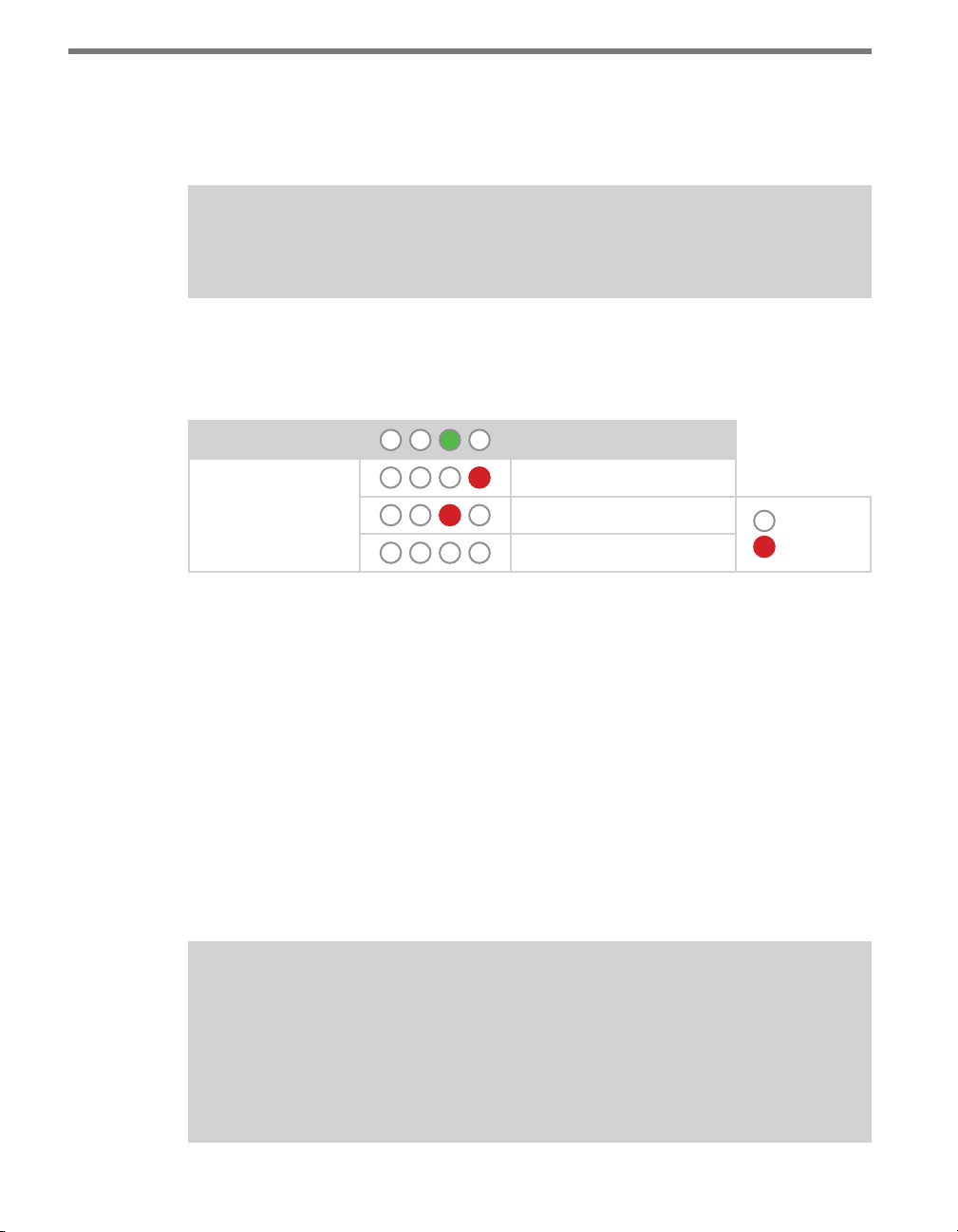
CHAPTER 9 CLICK 110 97
Autobaud
e second option that comes up when you’re cycling through the front panel menu is the
autobaud function. is option is indicated by the green LED coming on solid.
Note
The autobaud function can only be accessed here, on the front panel menu.
is function initiates an autobaud on the RS-485 buses (you will select which bus to autobaud on the Level 2 LEDs). An autobaud will stop data reporting on the selected port and
attempt to communicate with the SmartSensor at all supported baud rates.
Level 1 LEDs
Level 2 LEDs
Table 9.9 – Front Panel Menu Autobaud Settings
Autobaud
Autobaud on bus 1
Autobaud on bus 2
Cancel and exit menu
LED o
LED on
See the earlier Navigating through the Menu and the Menu Operation Example sections for
how to congure this parameter.
As each baud rate is attempted, the Level 2 LEDs will sequence with a single LED illuminated from LED 1–4.
If the Click 110 is successful in communicating with a SmartSensor, it will display the baud
rate found, using the same Level 2 LED system used in selecting the baud rate (covered in
the Baud Rate section of this chapter and Table 9.10). Aer a short time of displaying the
autobaud results, the menu will return to normal operation.
If the autobaud fails, all four Level 2 LEDs will ash once, and then the menu will return
to normal operation.
Note
If the baud rate of either of the RS-485 buses was configured using the DIP switches
(so that parameter is set to Hardware mode), the Level 2 LED configuration options
for that bus will not be displayed (the LED option will never come on). If both RS-485
buses are configured using the DIP switches, the Level 1 LED menu option for autobaud will not be displayed (the green LED option will never come on).
Page 99

98 CHAPTER 9 CLICK 110
Baud Rate (Bus 1 and 2)
e next two conguration parameters that come up in the front panel menu allow you to
manually set the baud rate of the two RS-485 buses. Bus 1 comes up rst, with the green and
yellow LEDs coming on together; bus 2 comes up second, with the blue LED glowing solid.
Note
This parameter can also be changed using the DIP switches or Click Supervisor.
Level 1 LEDs
Level 2 LEDs
Table 9.10 – Front Panel Menu Baud Rate Settings
Baud rate for bus 1
Baud rate for bus 2
9600 bps (default)
19200 bps
38400 bps
57600 bps
Cancel and exit menu
LED o
LED on
See the earlier Navigating through the Menu and the Menu Operation Example sections for
how to congure this parameter.
Because this parameter can also be set by the DIP switches, you may need to ensure that the
DIP switches are set to Soware conguration mode; if they are set to Hardware, the front
panel menu will be able to display but not change these settings.
Channel Enable
e next congurable parameter is enabling output channels. To select this parameter, release the push-button when the blue and yellow LEDs come on.
Note
This parameter can also be changed using the DIP switches or Click Supervisor.
A disabled output will never enter the detection state, and will never indicate a fault condition. Any combination of outputs can be enabled. Due to limited space on the side label,
Page 100

CHAPTER 9 CLICK 110 99
not all combinations of enabled and disabled channels are listed. A complete table is shown
bel ow.
Level 1 LEDs
Level 2 LEDs
Channel Enable
All o (default)
Channel 4 on
Channel 3 on
Channels 3 and 4 on
Channel 2 on
Channels 2 and 4 on
Channels 2 and 3 on
Channels 2, 3, and 4 on
Channel 1 on
Channels 1 and 4 on
Channels 1 and 3 on
Channels 1, 3, and 4 on
Channels 1 and 2 on
Channels 1, 2, and 4 on
Table 9.11 – Front Panel Menu Channel Enable Settings
Channels 1, 2, and 3 on
Channels 1, 2, 3, and 4 on
Cancel and exit menu
LED o
LED on
Note
If you are configuring the device with the front panel menu, it’s vital that you set up
your enabled channels; if you don’t, as you can see in the table, it will default to all
channels being disabled and the device will not work.
See the earlier Navigating through the Menu and the Menu Operation Example sections for
how to congure this parameter.
 Loading...