

Page 1
Click 400 900 MHz Radio
INSTALLER QUICK-REFERENCE GUIDE
Mount the device
1
e Click 400 mounts over a T-bus for power and communication:
1 If the Click 400 was shipped with the T-bus connector attached, re-
move the connector from the module.
2 Snap the connector onto the DIN rail by positioning it over the rail
with the male connector pointing to the right. Hook one arm over the
edge of the DIN rail and press down on the other arm until it snaps
into place.
3 Connect the T-bus connector to the rest of the T-bus by sliding them
together until you hear them snap into place.
4 Mount the Click 400 onto the DIN rail: position it properly over the
T-bus connector, hook the lip over the lower edge of the DIN rail, and
use a rocking motion to snap the module into place.
Wire power and communication
2
If you are using a Click 200 surge protector with the Click 400, power and communication are provided to
the Click 400 through the T-bus (see the Click 200 Quick-reference Guide). If you don’t have a Click 200
surge protector, use the following steps to wire power and communication into the Click 400:
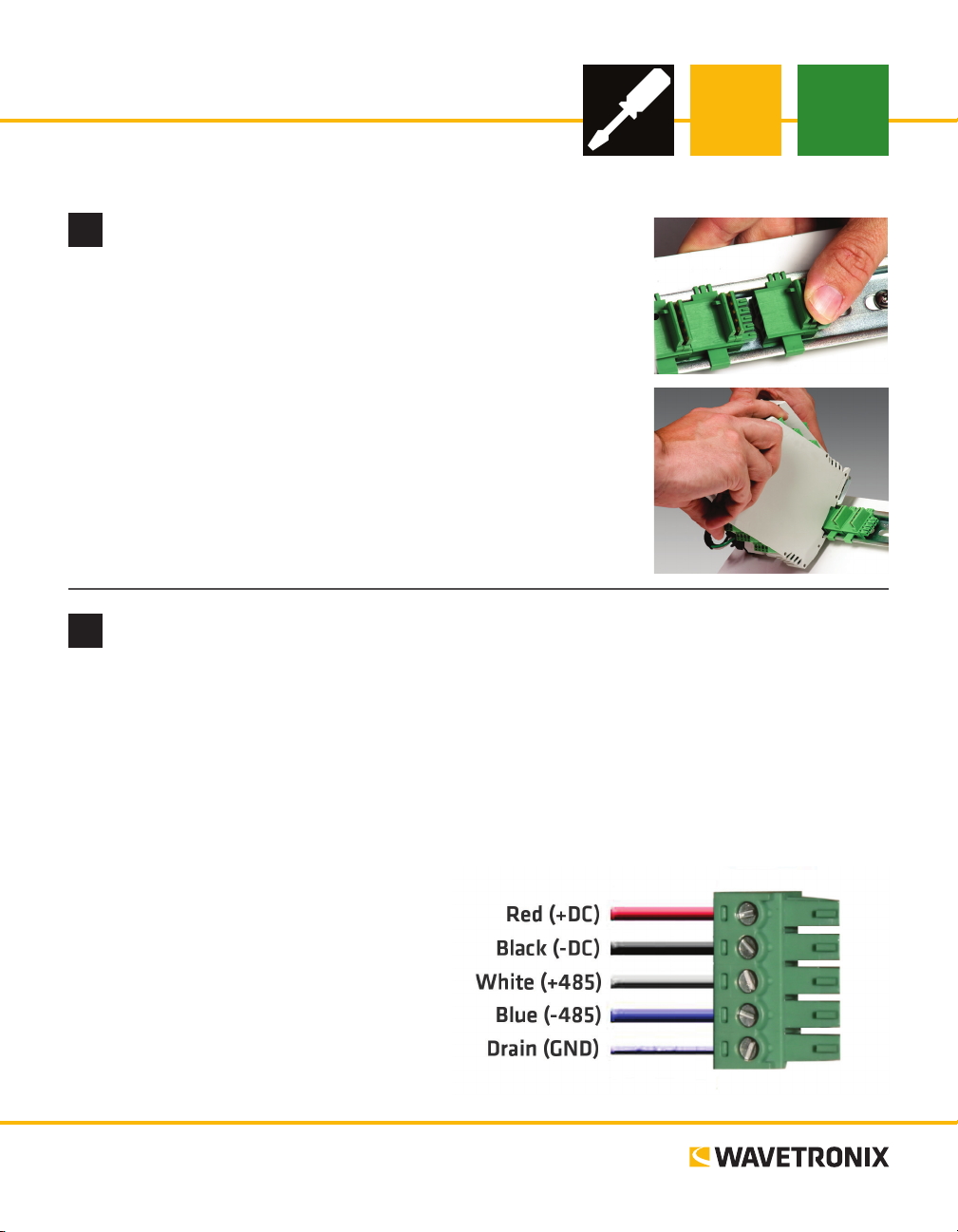
1 Plug a T-bus 5-screw terminal block into the rst T-bus connector.
2 Wire DC power (10–30 V) from the power supply into the rst screw terminal on the 5-screw terminal
block; wire -DC into the second screw terminal.
3 Connect RS-485 communication (+485, -485 and GND) to either the remaining three screw terminals
on the 5-screw terminal block or to the
screw terminals in the pluggable screw
terminal block on the top of the Click 400
(see labels for correct wiring).
e front of the Click 400 has one other communication port.
˽ DB-9 connector – Connect a straight-
through cable here for RS-232 communication
www.wavetronix.com
801.734.7200
Page 2
Attach the antenna
3
e Click 400 has a reversed polarity SMA antenna connector. A whip antenna can be used inside the
cabinet, though if it is inside a metal cabinet, the range will be diminished. An external antenna can also be
mounted on the exterior of the trac cabinet or up on a pole for maximum range. In that case, it is recommended you use a Click 250 wireless surge protector:
1 Connect the reversed polarity SMA connector of a coax cable to the Click 400 (antenna must be re-
moved), and connect the N connector to the nonbulkhead end of the Click 250.
2 Connect the N connector of another coax cable to the bulkhead end of the Click 250, and connect the
other end of the cable to the external antenna.
3 Attach a 12 AWG stranded copper grounding wire to the Click 250, then connect the grounding wire to
earth ground.
Use on-device configuration features
4
Use the device’s conguration features to make sure
the Click 400 is wired and working properly. e
Click 400 has four LEDs that monitor device activity and help you select operating modes, as well as
a push-button, labeled Mode Switch, also used for
operating modes.
1 Autobaud device (see table).
2 Set one of the devices as a server (by default, and
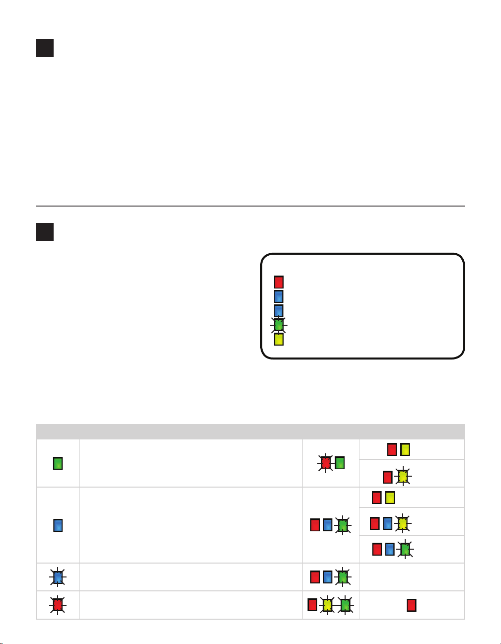
LED activity indicating functions:
Red – Device has power
Blue – Device is a client and can see a server
Blue flash – Device is a server
Green – Device is receiving data
Yellow – Device is transmitting data
aer a reset, the devices are clients) by setting it
in Link Test server mode. When the link test starts,
press the push-button again; the test will end and the device will stay a server. Your Click 400 installation will not work until you do this.
Hold the push-button to cycle through modes, then release when the desired mode is reached.
Selection Operating mode Running Completed
failure
Autobaud – Release push-button when green light is solid to
autobaud to sensor. Autobauding will set the device as a client.
Link Test (client) – Release push-button when blue LED is solid
to start Link Test mode as a client. The link test can’t be run until
the client and server devices are set to the same RF channel. See
Part 9.
Link Test (server) – Release push-button when blue LED is
blinking to start Link Test mode as a server.
Reset – Release push-button when red LED is blinking to reset to
factory defaults.
results will be shown on
success
can’t find server
invalid data
valid data
client module
Page 3

Install Click Supervisor
5
Click Supervisor will be used to congure the Click 400. To install it:
1 Download the setup le from www.wavetronix.com (under Support).
2 Double-click on the le to run the setup wizard. Follow the steps to install.
Make a connection
6
1 Make sure there is a connection between the Click 400 and the computer that
Click Supervisor is on. is can be through the DB-9 connector on the module
or through another device also on the T-bus; for example, the Click 421 can
communicate with the computer through Bluetooth®.
2 Run Click Supervisor and select Communication. e Click 400 can only be
congured using serial communication.
3 Click Settings to make any necessary changes to the settings, such as the port or
the baud rate. Click OK to return to the Communication screen, then click Connect. Keep the Click ID set to 0.
4 In the next screen, Click Supervisor will display all the devices it discovers.
When the Click 400 appears, select it and click Select. Click Supervisor will connect to the device.
Select a driver
7
1 Select Setup Click on the main screen.
2 Select the appropriate driver for your application:
˽ Client – If you connect multiple clients to a
single server
˽ Server – If you connect a single radio to another
single radio
Once that driver has loaded, you can use it to change functional and informational settings.
Configure the module
8
Change any necessary settings in the Setup tab (RF channel may be the only one that needs changing).
˽ Description/Location – For informational/identication purposes only.
˽ Device ID – Changes the ID number associated with the device. By default this is
the last ve digits of the serial number.
˽ RF Channel – e frequency channel of the device. If you perform a link test, each
client and server must be on the same channel.
˽ Tx Power – Lets you modify the transmit power level.
˽ Baud Rate – If connecting to a sensor, this must match the sensor’s baud rate.
˽ SmartSensor Client – If you connect a wireless
sensor station to a wireless base station
˽ SmartSensor Server – If you connect a wireless
base station to a wireless sensor station
˽ Expert – Use only when instructed to by Wa-
vetronix Technical Services
3 Click OK.
Page 4

Verify the connections
9
e Diagnostics tab has an RSSI display that shows the relative RSSI strength of the radio; it
is useful for detecting a low signal. Try one of the following if the RSSI signal is low:
˽ Boost the transmit power of the radio
˽ Check the gain on the antenna
˽ Replace the antenna
˽ Check line of sight to determine if any obstacles are blocking the signal
Verify wireless link
10
Make sure there is a valid wireless link between two Click 400 modules by performing a link test.
1 Use one of the drivers in Click Supervisor to set the two devices to the same RF channel.
2 Set one of the devices to Link Test mode as a server by pressing the push-button, then releasing when
the blue LED begins ashing. A server in Link Test mode will have a solid blue and red LED and the
green LED will begin ashing as it sends data for the test.
3 Set the other device in Link Test mode as a client by pressing the push-button then releasing when the
blue LED turns on solid. e client device will have a solid red LED.
4 Watch the client to be sure it has found a server: if the device nds a server on the same channel, the
blue LED will
be solid.
5 Once you’re
sure the client
has found a
server, watch
the LEDs on
the client to
see the results of the link test. A blinking green LED means that the client is receiving valid link test
data from the server; a ashing yellow LED means that the device is receiving invalid link test data; and
a solid yellow LED means no data is being received.
6 If the device is receiving invalid link test data, verify that the server is in link test mode. If this does not
x the problem, then check the line of sight and the antenna for possible problems.
7 Once the test is complete, the devices must be taken out of Link Test mode in order to operate. Press
and release the push-button on each device to exit Link Test mode.
Link test result Red LED Blue LED Green LED Yellow LED
Getting good data from server solid solid blinking –
Getting bad data from server solid solid – blinking
Cannot see server solid – – solid
Note. Once Link Test mode has been exited, the clients will remain clients and the servers will remain servers until they are set to be otherwise. A device must always be either a client or a server.
© 2014 Wavetronix LLC. All rights reserved. Protected by US Pat. Nos. 6,556,916; 6,693,557; 7,426,450; 7,427,930; 7,573,400; 7,889,097; 7,889,098; 7,924,170; 7,991,542; 8,248,272;
8,665,113; and Cdn. Pat. Nos. 2,461,411; 2,434,756; 2,512,689; and Euro. Pat. Nos. 1435036; 1438702; 1611458. Other US and international patents pending. Wavetronix, SmartSensor, Click,
Command and all associated logos are trademarks of Wavetronix LLC. All other product or brand names as they appear are trademarks or registered trademarks of their respective holders. Product specifications are subject to change without notice. This material is provided for informational purposes only; Wavetronix assumes no liability related to its use.
WX-500-0190
 Loading...