

Page 1
Click 330/331 Ethernet Switch
INSTALLER QUICK-REFERENCE GUIDE
Mount the device
1
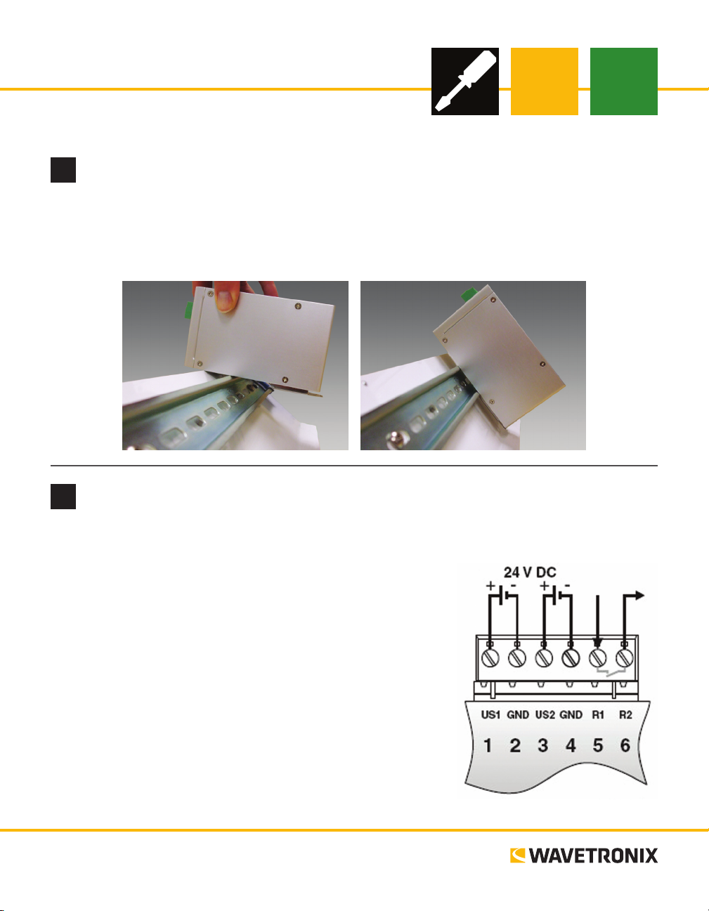
e Click 330/331 mount on a DIN rail. To mount, simply hook the lip over the lower edge of the DIN rail,
and use a rocking motion to snap the module into place.
Note. Do not mount over the T-bus.
Wire power
2
Unlike many other Click devices, the Click 330/331 do not mount over the T-bus, meaning that power and
communications will have to be wired in into the device’s six screw
terminals. e rst four screw terminals, marked US1, GND, US2 and
GND, are for wiring power. (e other two, which are labeled R1 and
R2, are for security and functionality alarm purposes.)
1 Attach the device to a location on the DIN rail that is not over a
T-bus.
2 Attach a wire for +DC (red is standard) to the screw terminal
marked US1.
3 Attach a wire for -DC (black is standard) to the rst screw termi-
nal marked GND.
4 Attach the other ends of these two wires to a DC power source.
Note. US2 and the second GND are for wiring in a redundant power
supply, if you’d like to use one.
www.wavetronix.com
801.734.7200
Page 2
Ground the device
3
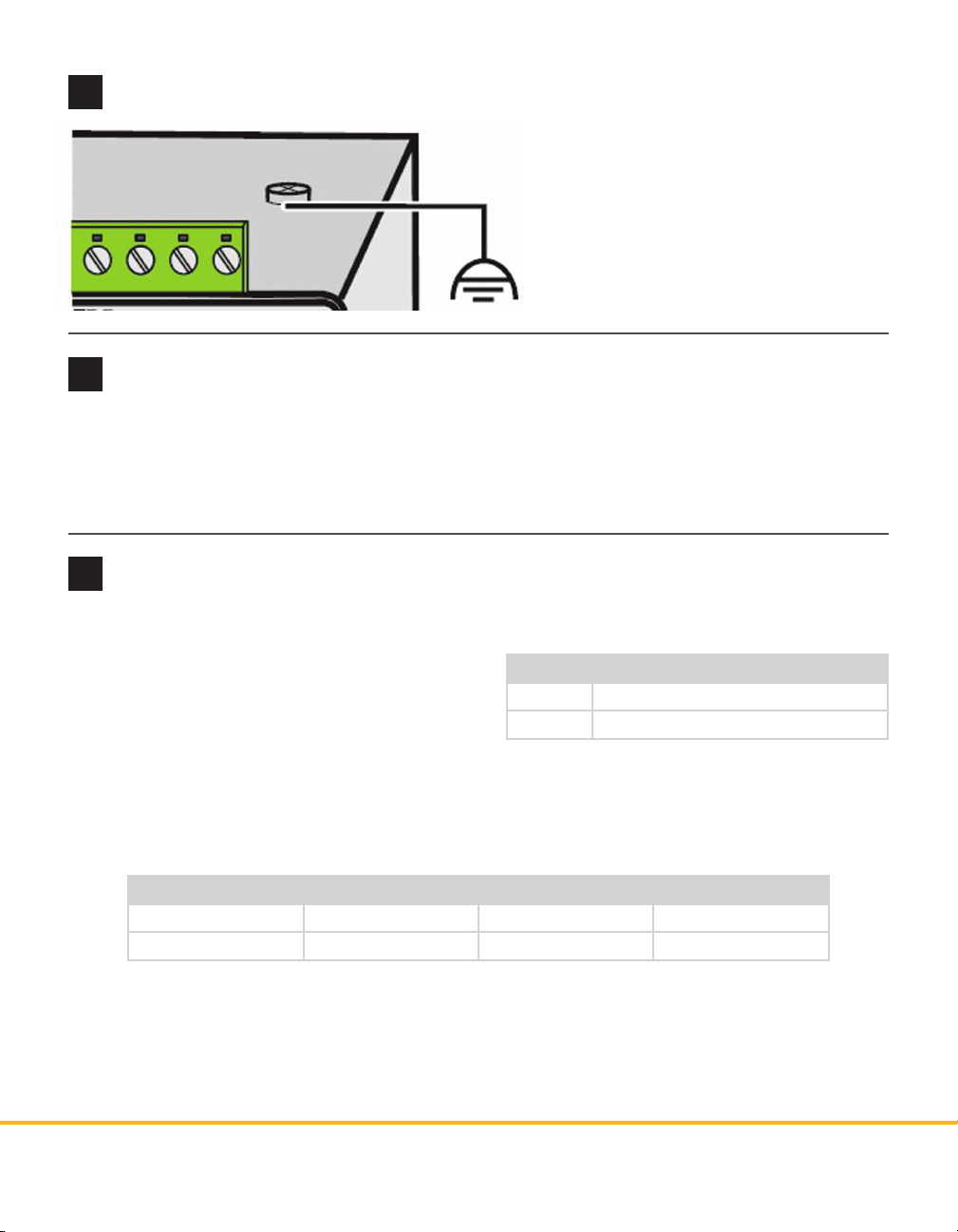
e device has a grounding foot, so as long as
the DIN rail is properly grounded, the device
will be grounded as well.
However, for additional protection, the switch
can be grounded via an eyelet ring on the top
of the device.
Wire communication
4
e Click 330/331 have two possible communication ports.
˽ RJ-45 jacks (Click 330 and 331) – Attach Ethernet cables here
˽ SC ber optic connectors (Click 331) – Attach ber optic cables by pushing the connector down until it
engages with a click
Monitor LEDs
5
e devices have three dierent kinds of LEDs.
˽ At the top of each device are two green LEDs
labeled US1 and US2, used for monitoring the
power supply. US1 monitors the rst power supply
(the one using the screw terminal marked US1)
and US2 monitors the second (redundant) power
supply.
˽ Each Ethernet port has two LEDs that show the data transmission speed of that port, as shown in the
table below. ese LEDs are labeled 100/ACT and 1000/ACT. If the LED is on, there is an electrical link.
If the LED blinks, there is currently network trac at that speed.
Status Meaning
On Supply voltage is in an acceptable range
O Supply voltage is too low
LED 10 Mbps 100 Mbps 1000 Mbps
100/ACT On or blinking On or blinking O
1000/ACT On or blinking O On or blinking
˽ e ber ports on the Click 331 each have an LED labeled 1000 LNK/ACT. If this LED is on, there is a
valid connection through that port. If the LED blinks, there is currently network trac at 1000 Mbps.
© 2014 Wavetronix LLC. All rights reserved. Protected by US Pat. Nos. 6,556,916; 6,693,557; 7,426,450; 7,427,930; 7,573,400; 7,889,097; 7,889,098; 7,924,170; 7,991,542; 8,248,272;
8,665,113; and Cdn. Pat. Nos. 2,461,411; 2,434,756; 2,512,689; and Euro. Pat. Nos. 1435036; 1438702; 1611458. Other US and international patents pending. Wavetronix, SmartSensor, Click,
Command and all associated logos are trademarks of Wavetronix LLC. All other product or brand names as they appear are trademarks or registered trademarks of their respective holders. Product specifications are subject to change without notice. This material is provided for informational purposes only; Wavetronix assumes no liability related to its use.
WX-500-0188
 Loading...