

Page 1
Click 304/305 USB to Serial
INSTALLER QUICK-REFERENCE GUIDE
is document covers the installation and conguration of both the Click 304 RS-232 to RS-485 converter and
the Click 305 USB to serial converter. e steps that follow apply to both devices unless stated.
Mount the device
1
Each device mounts over a T-bus for power and communication:
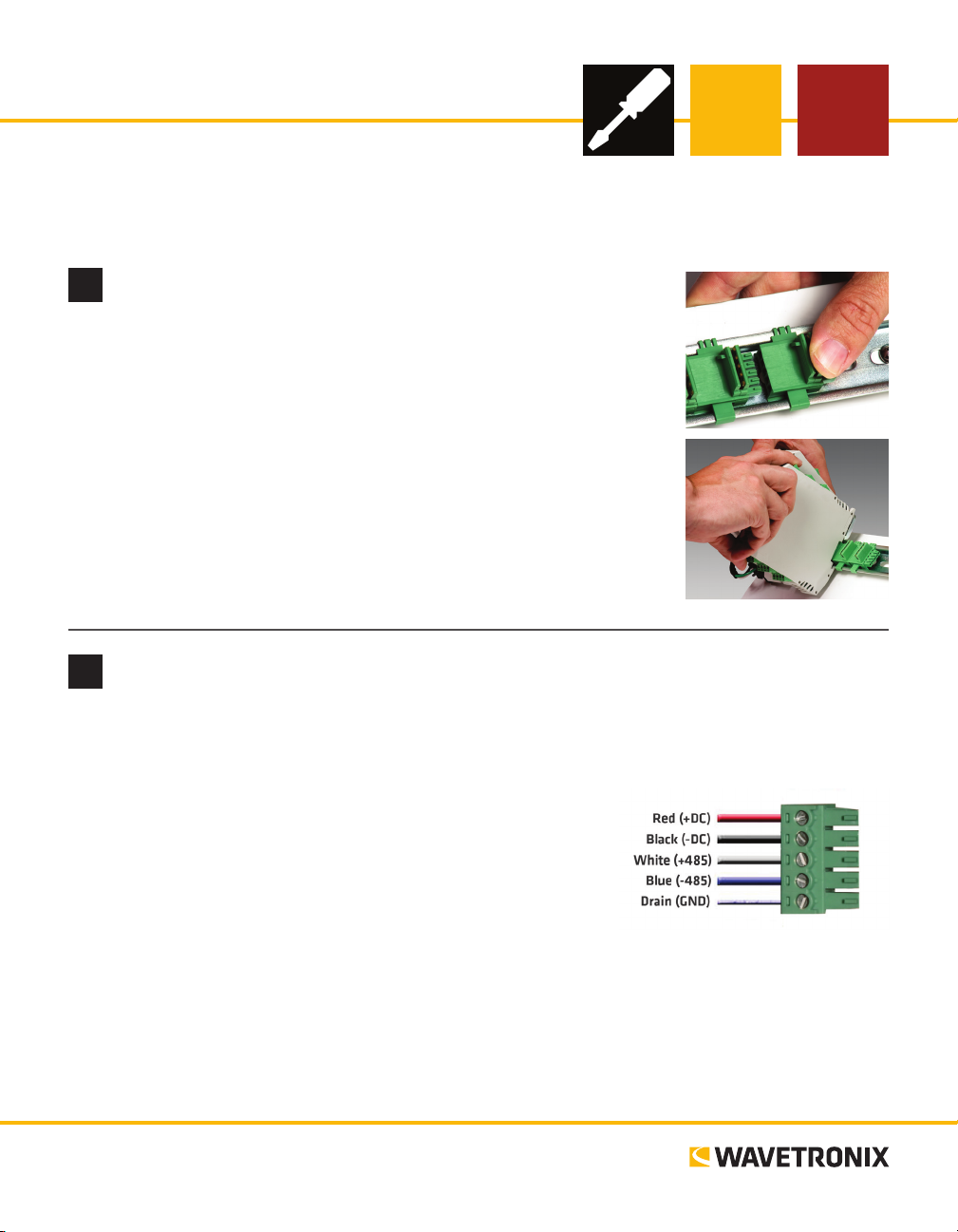
1 If the device was shipped with the T-bus connector attached, remove the
connector from the module.
2 Snap the connector onto the DIN rail by positioning it over the rail with
the male connector pointing to the right. Hook one arm over the edge of
the DIN rail and press down on the other arm until it snaps into place.
3 Connect the T-bus connector to the rest of the T-bus by sliding them
together until you hear them snap into place.
4 Mount the device onto the DIN rail: position it properly over the T-bus
connector, hook the lip over the lower edge of the DIN rail, and use a
rocking motion to snap the module into place.
Wire power and communication
2
If you are using a Click 200 surge protector, power and communication are provided to the device through
the T-bus (see the Click 200 Quick-reference Guide). If you don’t have a Click 200 surge protector, use the
following steps to wire power and communication into the device:
1 Plug a T-bus 5-screw terminal block into the rst T-bus connector.
2 Wire DC power (10–30 V) from the power supply into the rst
screw terminal on the 5-screw terminal block; wire -DC into the
second screw terminal.
3 Connect +485, -485 and GND to either the remaining three
screw terminals on the 5-screw terminal block or to the screw
terminals in the pluggable screw terminal block on the top of the
device (see labels for correct wiring).
Each device has several other communication ports.
˽ DB-9 connector (both devices) – Connect a straight-through cable for RS-232 communication
˽ RJ-11 jack (Click 304) – Connect a jumper cable for RS-485 communication
˽ USB connector (Click 305) – Accepts a USB 2.0 cable with a B-type plug (covered in Part 4)
www.wavetronix.com
801.734.7200
Page 2
Use on-device configuration features
3
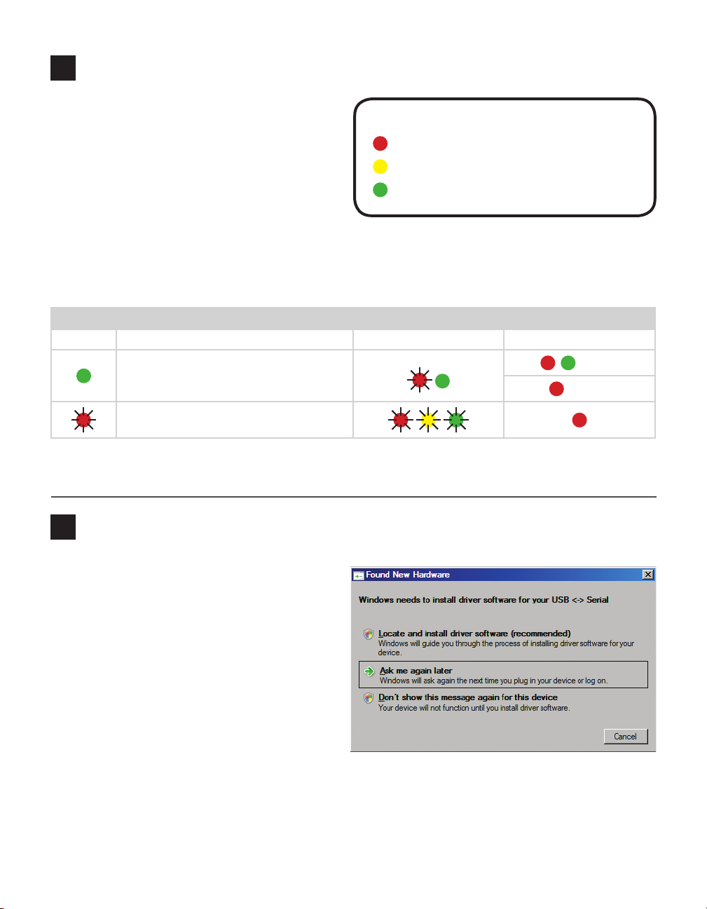
Next, use the device’s conguration features to
make sure it’s wired and working properly. e
Click 304 and 305 have three LEDs that monitor device activity and help you select operating
modes, as well as a push-button, labeled Mode
Switch, also used for operating modes.
1 Check LEDs to make sure the device has
power.
2 Autobaud device to make sure it can talk to the sensor or other attached serial device (see table).
Hold the push-button to cycle through modes, then release when the desired mode is reached.
LED operating mode indicating functions:
Selection Operating mode Running Completed
Autobaud – Release push-button when
green LED is solid to autobaud to sensor.
Reset – Release push-button when red LED
is blinking to reset to factory defaults.
Note. On certain devices, the yellow LED may replace the green LED in the autobaud process—that is, the
yellow LED selects the autobaud process, is on during the autobaud process, etc.
LED activity indicating functions:
Red – Shows device has power
Yellow – Shows device is transmitting data
Green – Shows device is receiving data
Failure
Success
Install USB drivers (Click 305 only)
4
Before connecting to the Click 305, USB drivers
need to be installed on your computer:
1 Find the Click305_USBDrivers.zip le on the
Wavetronix website.
2 Copy the zip le to your desktop and unzip
the les.
3 Connect a USB cable from your computer to
the Click 305. Once you have connected the
cable, a Found New Hardware window should
appear.
4 Select the Locate and install driver soware
option. Follow the steps to install the drivers.
5 Once you’ve installed once, the Found New Hardware box will come up a second time. Follow step 4 again.
Note. If you use a dierent USB port to connect the device another time, you will get the Found New Hard-
ware box again.
Page 3

Install Click Supervisor
5
Note. Your device is now fully functional. If you don’t wish to make any other
changes to conguration, you don’t need to follow the rest of the steps. However, the device can be further congured using Click Supervisor, soware
available from Wavetronix. Click Supervisor will enable you to view and change
certain settings that mostly help in identifying your device.
If you would like to install Click Supervisor, follow these steps:
1 Download the setup le from www.wavetronix.com (under Support).
2 Double-click on the le to run the setup wizard. Follow the steps to install.
Make a connection
6
1 Make sure there is a connection between the device and the computer that
Click Supervisor is on. is can be through the DB-9 connector on either
module, the USB port on the Click 305, or through another device also on
the T-bus.
2 Run Click Supervisor and select Communication. is screen lets you
pick the type of connection you want to make, serial or IP. e devices will
mostly likely be congured using serial communication.
3 Click Settings to make any necessary changes to the settings, such as the
port or the baud rate. Click OK to return to the Communication screen,
then click Connect. Keep the Click ID set to 0.
4 In the next screen, Click Supervisor will display all the devices it discovers.
When the device appears, select it and click Select. Click Supervisor will
connect to the device.
Select a driver
7
1 Select Setup Click on the main screen. You will see the following two driv-
ers:
˽ SmartSensor – is driver is used if you plan on connecting from a TOC
to your device to your sensor. You can use this driver to view and change
certain basic functional and informational settings such as baud rate, device description and device location.
˽ Expert – is driver exposes all device settings, and should be used only
when you are instructed to by Wavetronix Technical Services.
2 Select the driver you want and click OK.
Page 4

Configure the module
8
As mentioned in Part 5, your device can function properly without any settings being changed in Click Supervisor. e settings
listed below can be changed if you prefer, but it is not necessary
to do so.
SmartSensor Driver
˽ Device ID – Changes the ID number associated with the de-
vice. By default this is the last ve digits of the serial number.
˽ Baud rate – If connecting to a sensor, this must match the
sensor’s baud rate.
˽ Description/Location – For informational/identication purposes only. ese settings do not aect the
operation of the device.
Verify the connection
9
If you want to verify the serial connection on the Click 304:
1 Connect a straight-through cable between the DB-9 connector on the front of the Click 304 and your
computer.
2 Follow the steps in Part 6 of this document to make a connection to the Click 304 using Click Super-
visor. If you can talk to the device while physically connected to it, the serial connection is working
prope rly.
If you want to verify the serial connection on the Click 305:
1 Connect a USB cable between the USB connector on the front of the Click 305 and your computer.
2 Follow the steps in Part 6 of this document to make a connection to the Click 305 using Click Super-
visor (make sure to use the new com port that was assigned when you installed the Click 305 USB
drivers). If you can talk to the device while physically connected to it, the USB connection is working
prope rly.
© 2014 Wavetronix LLC. All rights reserved. Protected by US Pat. Nos. 6,556,916; 6,693,557; 7,426,450; 7,427,930; 7,573,400; 7,889,097; 7,889,098; 7,924,170; 7,991,542; 8,248,272;
8,665,113; and Cdn. Pat. Nos. 2,461,411; 2,434,756; 2,512,689; and Euro. Pat. Nos. 1435036; 1438702; 1611458. Other US and international patents pending. Wavetronix, SmartSensor, Click,
Command and all associated logos are trademarks of Wavetronix LLC. All other product or brand names as they appear are trademarks or registered trademarks of their respective holders. Product specifications are subject to change without notice. This material is provided for informational purposes only; Wavetronix assumes no liability related to its use.
WX-500-0183
 Loading...