

Page 1
Click 301 Serial to Ethernet
INSTALLER QUICK-REFERENCE GUIDE
Mount the device
1
e Click 301 mounts over a T-bus for power and communication:
1 If the Click 301 was shipped with the T-bus connector attached,
remove the connector from the module.
2 Snap the connector onto the DIN rail by positioning it over the rail
with the male connector pointing to the right. Hook one arm over
the edge of the DIN rail and press down on the other arm until it
snaps into place.
3 Connect the T-bus connector to the rest of the T-bus by sliding
them together until you hear them snap into place.
4 Mount the Click 301 onto the DIN rail: position it properly over the
T-bus connector, hook the lip over the lower edge of the DIN rail,
and use a rocking motion to snap the module into place.
Wire power and communication
2
If you are using a Click 200 surge protector with the Click 301, power and communication are provided
to the Click 301 through the T-bus (see the Click 200 Quick-reference Guide). If you don’t have a Click 200
surge protector, use the following steps to wire power and communication into the Click 301:
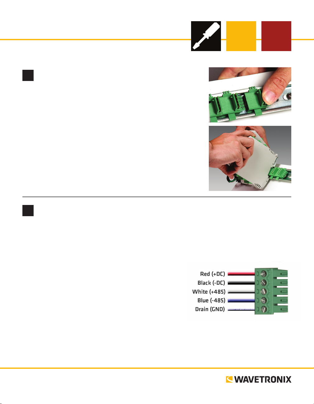
1 Plug a T-bus 5-screw terminal block into the rst T-bus connector.
2 Wire DC power (10–30 V) from the power supply into the
rst screw terminal on the 5-screw terminal block; wire
-DC into the second screw terminal.
3 Connect RS-485 communication (+485, -485 and GND) to
either the remaining three screw terminals on the 5-screw
terminal block or to the screw terminals in the pluggable
screw terminal block on the top of the Click 301 (see labels
for correct wiring).
e front of the Click 301 has two other communication ports.
˽ DB-9 connector – Connect a straight-through cable here for RS-232 communication
˽ RJ-45 jack – Connect an Ethernet cable here to communicate over an Ethernet network
www.wavetronix.com
801.734.7200
Page 2
Use on-device configuration features
3
Next, use the device’s conguration features to
make sure the Click 301 is wired and working
properly. e Click 301 has three LEDs that monitor device activity and help you select operating
modes, as well as a push-button, labeled Mode
Switch, also used for operating modes.
1 Check LEDs to make sure the device has power.
2 Autobaud device to make sure it can talk to the
sensor or other attached serial device (see table).
Hold the push-button to cycle through modes, then release when the desired mode is reached.
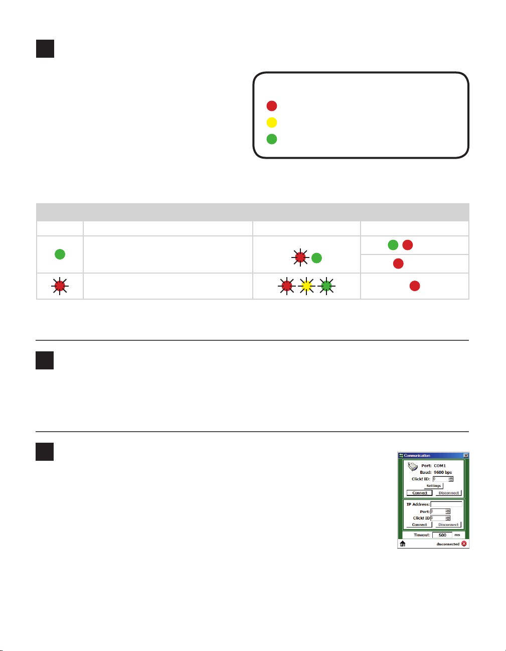
LED activity indicating functions:
Red – Shows device has power
Yellow – Shows device is transmitting data
Green – Shows device is receiving data
LED operating mode indicating functions:
Selection Operating mode Running Completed
Autobaud – Release push-button when
green LED is solid to autobaud to sensor.
Reset – Release push-button when red LED
is blinking to reset to factory defaults.
Note. On some devices, the yellow LED may replace the green LED in the autobaud process—that is, the
yellow LED selects the autobaud process, is on during the autobaud process, etc.
Failure
Success
Install Click Supervisor
4
Click Supervisor will be used to congure the Click 301. Follow these steps to install it:
1 Download the setup le from www.wavetronix.com (under Support).
2 Double-click on the le to run the setup wizard. Follow the steps to install.
Make a connection
5
1 Make sure there is a connection between the Click 301 and the computer that
Click Supervisor is on. is can be through the DB-9 connector on the module or
through another device also on the T-bus; for example, the Click 421 can communicate with the computer through Bluetooth®.
2 Run Click Supervisor and select Communication. is screen lets you pick the
type of connection you want to make, serial or IP. e Click 301 must be congured using serial communication.
3 Click Settings to make any necessary changes to the settings, such as the port or the baud
rate. Click OK to return to the Communication screen, then click Connect. Keep the Click ID set to 0.
4 In the next screen, Click Supervisor will display all the devices it discovers. When the Click 301 ap-
pears, select it and click Select. Click Supervisor will connect to the device.
Page 3

Select a driver
6
1 Select Setup Click on the main screen.
2 Select the appropriate driver for your application:
˽ SmartSensor – If you connect from a TOC to Click 301 to sensor
˽ Point to Point – If you connect from a TOC to Click 301 to another Click
301 to sensor
˽ Expert – Use only when instructed to by Wavetronix Technical Services
3 Click OK.
Once that driver has loaded, you can use it to change function settings such as
baud rate as well as to change informational settings such as device location and
description. You can also use the driver to view device information such as serial
number and rmware version.
Configure the module
7
Change the appropriate settings below. Only the IP address and port–related settings are necessary for
device functionality.
SmartSensor Driver
˽ Description/Location – For informational/identication purposes only.
ese settings do not aect the operation of the device.
˽ Device ID – Changes the ID number associated with the device. By default
this is the last ve digits of the serial number.
˽ Baud rate – If connecting to a sensor, this must match the sensor’s baud rate.
˽ IP Address – Change this setting to the desired IP address of the device.
Default is 172.16.0.13.
˽ IP Port – Change this setting to the desired IP port of the device. Default is
10001.
Point to Point Driver
˽ Description/Location – For informational/identication purposes only.
ese settings do not aect the operation of the device.
˽ Device ID – Changes the ID number associated with the device. By default
this is the last ve digits of the serial number.
˽ Baud rate – If connecting to a sensor, this must match the sensor’s baud rate.
˽ IP Address / IP Port – See SmartSensor driver above.
˽ Remote IP Address – Change this setting to the IP address of the device you
want your device to connect to. Default is 172.16.0.14.
˽ Remote IP Port – Change this setting to the IP port of the device you want
your device to connect to. Default is 10001.
Page 4

Verify the connection
8
Follow the steps below to verify the Ethernet/IP connection using your laptop.
1 Set up a static IP on the PC by going to Windows Start Menu > Settings > Control Panel > Network
> Network Connections. Select the Ethernet Connection, click the right mouse button, and select
Properties. Select Internet Protocol, and click on Properties. If the Click 301 IP address is on the
172.16.0.xxx, input a static IP address for the laptop that is dierent from any other devices on the network, such as 172.16.0.250 and a subnet of 255.255.255.0 and then click OK.
2 Connect a crossover Ethernet cable between the laptop and the Ethernet port on the Click 301.
3 To check the connection, ping the Click 301: go to the Start menu and select Run. Type “cmd” into the
dialog box that appears. e cmd.exe program will open.
4 Type “ping” followed by the IP address of the Click 301. Hit Enter. If you get a response, the connection
is working properly. If the request times out or you get a message saying the IP address could not be
found, something is wrong with your Click 301 Ethernet connection.
© 2014 Wavetronix LLC. All rights reserved. Protected by US Pat. Nos. 6,556,916; 6,693,557; 7,426,450; 7,427,930; 7,573,400; 7,889,097; 7,889,098; 7,924,170; 7,991,542; 8,248,272;
8,665,113; and Cdn. Pat. Nos. 2,461,411; 2,434,756; 2,512,689; and Euro. Pat. Nos. 1435036; 1438702; 1611458. Other US and international patents pending. Wavetronix, SmartSensor, Click,
Command and all associated logos are trademarks of Wavetronix LLC. All other product or brand names as they appear are trademarks or registered trademarks of their respective holders. Product specifications are subject to change without notice. This material is provided for informational purposes only; Wavetronix assumes no liability related to its use.
WX-500-0182
 Loading...