

Page 1
Click 200 Lightning Surge
INSTALLER QUICK-REFERENCE GUIDE
Mount the device
1
e Click 200 mounts over a T-bus for power and communication:
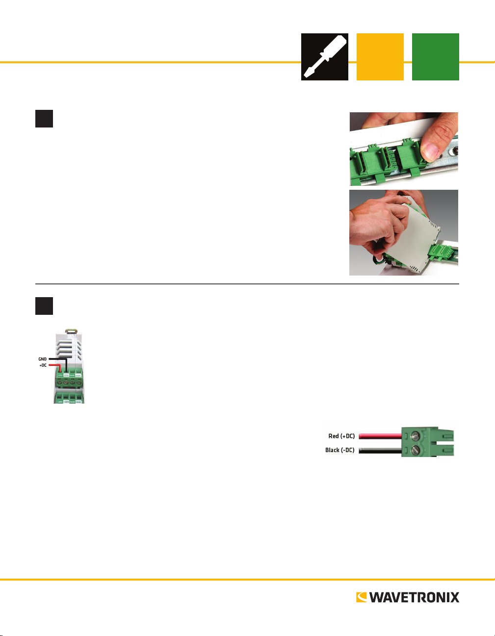
1 If the Click 200 was shipped with the T-bus connector attached, remove
the connector from the module.
2 Snap the connector onto the DIN rail by positioning it over the rail with
the male connector pointing to the right. Hook one arm over the edge of
the DIN rail and press down on the other arm until it snaps into place.
3 Connect the T-bus connector to the rest of the T-bus by sliding them
together until you hear them snap into place.
4 Mount the Click 200 onto the DIN rail: position it properly over the T-
bus connector, hook the lip over the lower edge of the DIN rail, and use a
rocking motion to snap the module into place.
Wire power and communication
2
e Click 200 can take power and communications in through its screw terminals and send
it through any T-bus it is mounted on. To wire power through the Click 200: wire +DC from
the power supply into the screw terminal marked +DC on the PROTECTED side of the
Click 200. Wire -DC from the power supply into the screw terminal marked -DC.
Alternatively, power can be wired from the power supply into a 5-screw terminal block,
which can then be plugged into the le side of the T-bus. To wire power through the 5-screw
terminal block: wire +DC from the power supply into
the screw terminal marked +DC on the 5-screw terminal block. Wire
-DC from the power supply into the screw terminal marked -DC.
e front of the Click 200 has two communication ports (communication through the device’s screw terminals will be covered in Part 4).
˽ RJ-45 jack – A convenient way to connect RS-485 communications to a rack card
˽ DB-9 connector – Connect between here and your computer to congure your sensor
Note. Unlike on other Click devices, the RS-232 lines are not connected to the RS-485 lines on the Click
200. Be sure to test both lines as part of your installation process.
www.wavetronix.com
801.734.7200
Page 2
Wire earth ground
Smart
Sensor
120
VAC
3
All Click 200 devices should be mounted on a DIN rail that is connected to earth ground, either through
an earth-grounded chassis or a 16 AWG or larger grounding wire attached to a 7-. (2.1-m) grounding rod.
Follow the steps below to correctly wire to earth ground:
1 Connect the grounding wire from either the DIN rail or a GND screw terminal on the UNPROTECT-
ED side of the Click 200 to the lug bolt on the inside of the pole-mount box.
2 Connect another grounding wire from the exterior lug bolt to earth ground.
Connect cables
4
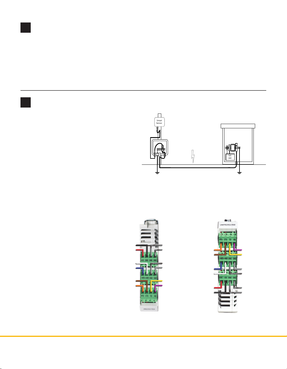
e Click 200 does three things in a sensor
Main Trac Cabinet
installation: rst, it sends power from the power
plant to the sensor. Second, it passes serial communications between sensor and cabinet and
between dierent cabinets. Finally, it surge
protects sensors and cabinets. If your installation
Pole
Mount
Trac
Cabinet
Both ends of the homerun
cable connect to the
UNPROTECTED side of
the surge modules.
has an underground cable run, use two Click 200
devices: one in the pole-mount cabinet, the other
in the main trac cabinet, as shown above. ese
devices protect the sensor and the main trac
cabinet from surges on the underground cable run caused by lightning striking the ground nearby.
Note. ere are two cables your Click 200 could use. To tell which one you have, look at the connector: the
SmartSensor cable has the larger 26-pin connector and the 8-conductor cable has the smaller 10-pin connector. e wiring of these two cables
will vary slightly, as outlined below.
1 Run a cable from the sensor into
the pole-mount cabinet. Wire it
into the PROTECTED side of the
Click 200 (as shown near right).
2 Wire a second cable into the UN-
PROTECTED side (as shown far
right). Run that cable from the
pole-mount cabinet to the main
trac cabinet.
3 Wire that cable into the UN-
GND/-DC (Black)
+DC (Red)
+485 (White)
-485 (Blue)
CTS (Brown)
RTS (Orange)
Power Drain
RS-232 Drain
RS-485 Drain
Ground (Gray)
TD (Yellow)
RD (Purple)
RTS (Orange)
CTS (Brown)
-485 (Blue)
+485 (White)
+DC (Red)
-DC (Black)
RD (Purple)
TD (Yellow)
Ground (Gray)
RS-485 Drain
RS-232 Drain
Power Drain
PROTECTED side of the second
Click 200.
The 8-conductor cable diers from the images above in these ways:
there’s no gray ground wire; there’s only one drain, which can be
connected to any GND terminal; the white +485 wire has a blue stripe.
© 2014 Wavetronix LLC. All rights reserved. Protected by US Pat. Nos. 6,556,916; 6,693,557; 7,426,450; 7,427,930; 7,573,400; 7,889,097; 7,889,098; 7,924,170; 7,991,542; 8,248,272;
8,665,113; and Cdn. Pat. Nos. 2,461,411; 2,434,756; 2,512,689; and Euro. Pat. Nos. 1435036; 1438702; 1611458. Other US and international patents pending. Wavetronix, SmartSensor, Click,
Command and all associated logos are trademarks of Wavetronix LLC. All other product or brand names as they appear are trademarks or registered trademarks of their respective holders. Product specifications are subject to change without notice. This material is provided for informational purposes only; Wavetronix assumes no liability related to its use.
WX-500-0179
 Loading...