

Page 1
Click 104 Contact Closure
INSTALLER QUICK-REFERENCE GUIDE
Understand buses
1
e 104 installation process will make more sense if you understand its two buses:
˽ Bus 1: Data – e RJ-11 jacks (for RS-485) and the RS-232 screw terminals
are connected; theyll be used for receiving detection calls
˽ Bus 2: Control – e connector on the back connects to the T-bus (shared
RS-485 bus for multiple Click devices) and is isolated from bus 1; it should be
used to connect to the Click 104 with a computer so you can congure it.
Mount the device
2
e Click 104 mounts over a T-bus for power and for the control bus (bus 2):
1 If the Click 104 was shipped with the T-bus connector attached, remove the
connector from the module.
2 Snap the connector onto the DIN rail by positioning it over the rail with the
male connector pointing to the right. Hook one arm over the edge of the
DIN rail and press down on the other arm until it snaps into place.
3 Connect the T-bus connector to the rest of the T-bus by sliding them to-
gether until you hear them snap into place.
4 Mount the Click 104 onto the DIN rail: position it properly over the T-bus
connector, hook the lip over the lower edge of the DIN rail, and use a rocking motion to snap the module into place.
RS-232
Bus 1
Data
+DC
Bus 2
-DC
Control
+485
-485
GND
Click
104
Contact
Closures
3-4 1-2
Bus 1
Data
RS-485
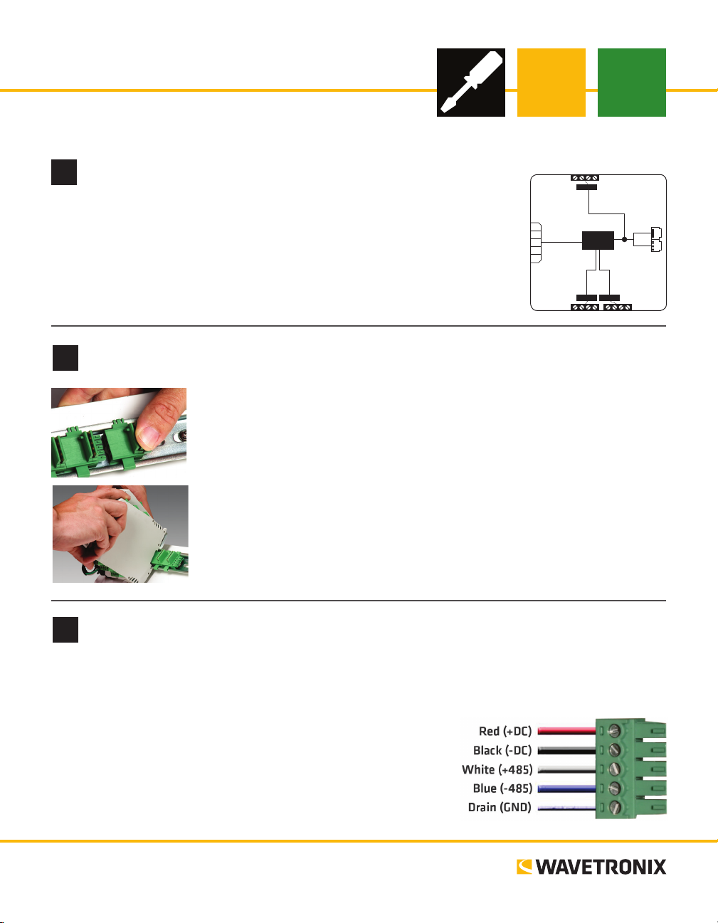
Wire power and RS-485 communication
3
If you are using a Click 200 surge protector with the Click 104, power and communication are provided to
the Click 104 through the T-bus (see the Click 200 Quick-reference Guide). If you don’t have a Click 200
surge protector, use the following steps to wire power and communication into the Click 104:
1 Plug a T-bus 5-screw terminal block into the rst T-bus connector.
2 Wire DC power (9–28 V) from the power supply into the rst
screw terminal on the 5-screw terminal block; wire -DC into the
second screw terminal.
3 Connect RS-485 communication (+485, -485 and GND) to the
remaining three screw terminals on the 5-screw terminal block.
www.wavetronix.com
801.734.7200
Page 2
Understand the device’s configuration features
4
e following physical features allow you to congure the Click 104:
˽ Channel LEDs – e top bank of LEDs; these light up to indicate vehicle detection.
˽ Level 2 LEDs – Light up to indicate conguration options. When the device is not in
menu mode, these LEDs are o.
˽ Level 1 LEDs – Light up to indicate menu options while cycling through the menu. ey
also have the following functions:
˿ Red (PWR) – Indicates the presence of power to the device.
˿ Blue (OK) – Indicates the device is operating properly; this LED goes out if the
device is in fail-safe mode.
˿ Green (TD) – Indicates serial communication transmit data on RS-485 bus 1 or 2.
˿ Yellow (RD) – Indicates serial communication receive data on RS-485 bus 1 or 2.
˽ Mode Switch – Lets you cycle through and select menu and conguration options.
˽ Rotary Switch – Aids in input channel mapping.
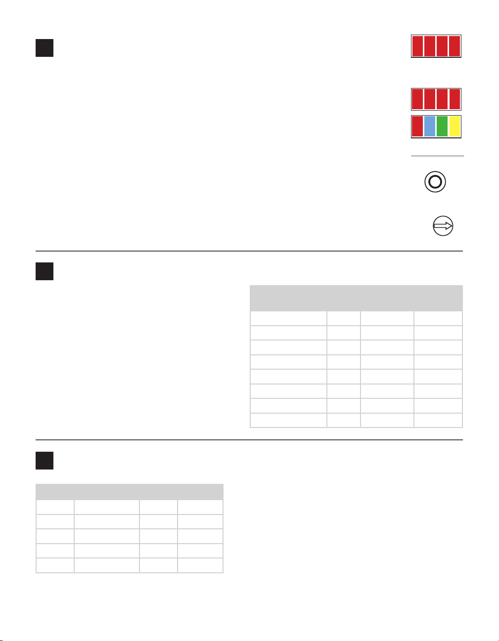
Select configuration method
5
e Click 104 can be congured in one of three
ways: Click Supervisor, the front panel menu and
the rotary switch. Each option has pros and cons,
and each lets you change dierent parameters;
some parameters can only be set via one option,
while others can be set using any of the three. e
table at right gives you an idea of which parameters
can be set using which conguration options.
NOTE: If the channel input mapping is set by the
rotary switch, it can’t be changed by the front panel
menu or by Click Supervisor.
Rotary
Switch
Baud Rate No Yes Yes
Channel Input Map Yes Yes Yes
Autobaud No Yes No
Reset to Default No Yes Yes
Description No No Yes
Location No No Yes
Device ID No No Yes
Fail-safe Settings No No Yes
Front Panel
Menu
Channel
1 2 3 4
Menu
PWR OK TD RD
Mode Switch
Mapping
8
7
9
6
0
5
1
4
2
3
Click
Supervisor
Configuration option 1: rotary switch
6
Switch Channels Switch Channels
0 Software mode 5 17–20
1 1–4 6 21–24
2 5–8 7 25–28
3 9–12 8 29–32
4 13–16 9 33–36
e rotary switch on the faceplate lets you congure the
channel input mapping—that is, you can map four of the
input data channels coming from the sensor to the Click
104’s four output channels. e outputs are assigned
sequentially, so if you set the switch to 3, then input 9
will be mapped to channel 1, input 10 will be mapped to
channel 2, and so on. See the table at the right for switch/
input channel information.
NOTE: 0 (Soware mode) means that if mapping isn’t set by the rotary switch, it can be changed via the
front panel menu or Click Supervisor.
Page 3

Configuration option 2: front panel menu
Menu Operation
•
7
e front panel menu allows you to congure input mapping and baud rates. It can also reset the device to
factory defaults, and is the only place on the device to access the autobaud function.
Menu and conguration options are displayed on the Level 1 and Level 2 LEDs on the faceplate. Navigate
through the menu using the mode switch:
1 Press and hold the mode switch to enter Menu mode. e Level 1 LEDs will start to light up to indicate
that the device is cycling through all menu options.
2 When the LEDs light up in the way that indicates the menu option you want (see the gure below),
release the mode switch.
3 Quickly press and release the mode switch to select the current menu option. e Level 2 LEDs will
light up to let you congure the options for the selected menu option.
4 Press and hold the mode switch to cycle through available values for the selected menu option. e
Level 2 LEDs display the currently selected value.
5 Press and release the mode switch to accept the displayed value. e device will exit the menu.
See the gure below for how to use the LEDs to congure the parameter.
Channel Input Mapping
is function lets you map four of the input
data channels coming from the sensor to the
= LED O
= LED Flashing
= LED On
four output channels on the device. See part 5
for more information.
NOTE: If this is set with the rotary switch, you
won’t be able to change it with the front panel
menu.
Autobaud
Input Mapping
Menu LEDs
1 2 3 4
is function initiates an autobaud on the
RS-485 bus you select. If the autobaud is successful, the LEDs will display the baud rate
found, using the same LED patterns used for
the baud rate (see gure above). If it fails, all
four LEDs will ash, and then the device will
exit the menu.
Baud Rate for Bus 1 and Bus 2
is function lets you set the baud rate for bus
1 and bus 2. e two buses can be congured separately.
PUSH and HOLD Mode Switch to
cycle through menus and options.
R B G Y
Reset to Default
Menu LEDs
1 2 3 4
Cancel
Reset
R B G Y
Bus 2 Baud Rate
Menu LEDs
1 2 3 4
Cancel
9600
19200
38400
57600
R B G Y
Cancel
1-4
5-8
9-12
13-16
17-20
21-24
25-28
29-32
33-36
R B G Y
Autobaud
Menu LEDs
1 2 3 4
Cancel
Bus 1
Bus 2
R B G Y
Bus 1 Baud Rate
Menu LEDs
1 2 3 4
Cancel
9600
19200
38400
57600
This label is also on the side of the Click 104
• PUSH and
RELEASE
Mode Switch
to make
selections.
• 1 minute of
inactivity exits
menu.
Rotary
Switch
1
2
3
4
5
6
7
8
9
= SW0
= 1-4
= 5-8
= 9-12
= 13-16
= 17-20
= 21-24
= 25-28
= 29-32
= 33-36
8
7
9
6
5
4
2
3
0
1
Reset to Default
is function will restore all conguration settings to factory defaults (even those not congured using the
front panel menu): baud rate, channel map, description eld, location eld and device ID.
Page 4

Configuration option 3: Click Supervisor
8
Click Supervisor is the third available way to congure the Click 104. To install it, download the setup le
from www.wavetronix.com (under Support) and double-click on the le to run the setup wizard.
Make a connection and select a driver
1 Make sure the Click 104 is mounted on the same T-bus as a device that’s connected to your computer.
2 Run the soware and click Communication. Use the serial option (unless it’s an Ethernet connection).
3 Change any needed settings under the Settings link. Click Connect. (Keep the Click ID set to 0.)
4 In the next screen, Click Supervisor will display all the devices it discovers. When the desired Click 104
appears, select it and click Select. Click Supervisor will connect to the device.
5 Select Setup Click on the main screen. In the next screen, select the Expert driver and click OK.
Configure the module
e System > General tab has text parameters that cannot be changed anywhere
else: description/location, which are for informational purposes only; and device
ID, which usually shouldn’t be changed.
e Settings tab lets you set channel input mapping and select baud rates for the two
buses. Failsafe Enabled sets whether or not your device can enter fail-safe mode.
NOTE: Remember that if channel input mapping is set by the rotary switches, you
will only be able to view, not change, it here.
Complete wiring
9
Now you need to connect the Click 104 to the sensor (so that it can receive detection
data) and to the controller or other contact closure device.
To get detection data to bus 1:
˽ For a SmartSensor Matrix or Advance (meaning a Click 222 or 223 surge pro-
tector): connect a jumper cable to the Click 222 RJ-11 jack for the sensor you
want to get data from. Connect the other end to either of the RJ-11 jacks on the
faceplate of the Click 104. If you need more than four output channels for that
sensor, daisy-chain multiple 104s together, as shown at right.
˽ For a SmartSensor HD (meaning a Click 200): set the HD to push Z4 data on the
RS-232 port. Attach wires to the TD and RD screw terminals on the protected side
of the Click 200; attach the other ends to the TD and TD screw terminals on the
104. If needed, daisy-chain multiple 104s together with jumper cables.
How you wire the contact closures will vary based on the controller or other device you use.
Just be aware there are eight output screw terminals: a + and a – for each output channel.
© 2014 Wavetronix LLC. All rights reserved. Protected by US Pat. Nos. 6,556,916; 6,693,557; 7,426,450; 7,427,930; 7,573,400; 7,889,097; 7,889,098; 7,924,170; 7,991,542; 8,248,272;
8,665,113; and Cdn. Pat. Nos. 2,461,411; 2,434,756; 2,512,689; and Euro. Pat. Nos. 1435036; 1438702; 1611458. Other US and international patents pending. Wavetronix, SmartSensor, Click,
Command and all associated logos are trademarks of Wavetronix LLC. All other product or brand names as they appear are trademarks or registered trademarks of their respective holders. Product specifications are subject to change without notice. This material is provided for informational purposes only; Wavetronix assumes no liability related to its use.
WX-500-0252
 Loading...