

Page 1
SmartSensor HD
INSTALLER QUICK-REFERENCE GUIDE
Introduction
Complete steps 1–10 to install the Wavetronix SmartSensor HD. If you need
technical support or have questions, please contact Wavetronix Technical
Services at 801.734.7200. For more information, see the SmartSensor HD
User Guide.
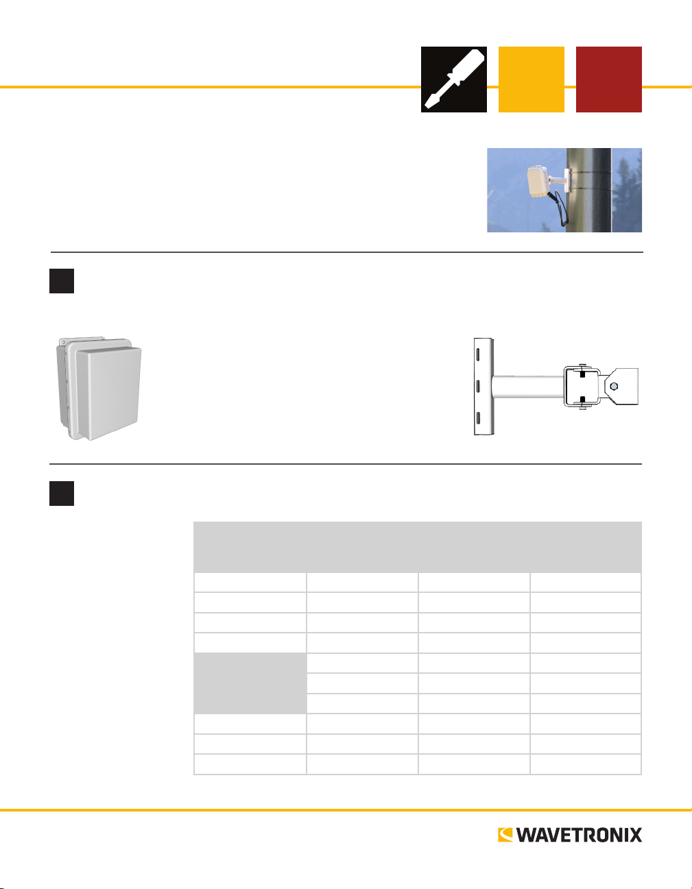
Ensure that all necessary components are available
1
You will need a number of items in order to install your sensor, including but not limited to the items below:
˽ Mount bracket and Band-It clamping system
˽ Sensor cable and homerun cable
˽ Click equipment and pole-mount box
˽ Laptop or PDA with SmartSensor Manager HD
˽ Bucket truck
˽ Pertinent documentation
Select a mounting height
2
Use the table to select
the mounting height
for the sensor based
on the oset from the
nearest detection lane.
e range of ideal
osets is highlighted
in gray.
If possible, use the
mounting height contained in the second
column, which is
marked Recommended
Mounting Height.
www.wavetronix.com
801.734.7200
Oset from first
Detection Lane
(ft/m)
6 / 1.8 12 / 3.7 9 / 2.7 19* / 5.8*
10 / 3 12 / 3.7 9 / 2.7 22 / 6.7
15 / 4.6 15 / 4.6 12 / 3.7 26 / 7.9
20 / 6 18 / 5.5 15 / 4.6 30 / 9.1
25 / 7.6 26 / 7.9 17 / 5.2 33 / 10
30 / 9.1 29 / 8.8 19 / 5.8 37 / 11.2
35 / 10.7 30 / 9.1 20 / 6 40 / 12.2
40 / 12.2 33 / 10 22 / 6.7 43 / 13.1
45 / 13.7 36 / 11 23 / 7 40 / 14
50 / 15.2 39 / 11.9 25 / 7.6 50 / 15.2
Recommended
Mounting Height
(ft/m)
Minimum
Mounting Height
(ft/m)
*Reduction in number of reported speeds
Maximum
Mounting Height
(ft/m)
Page 2
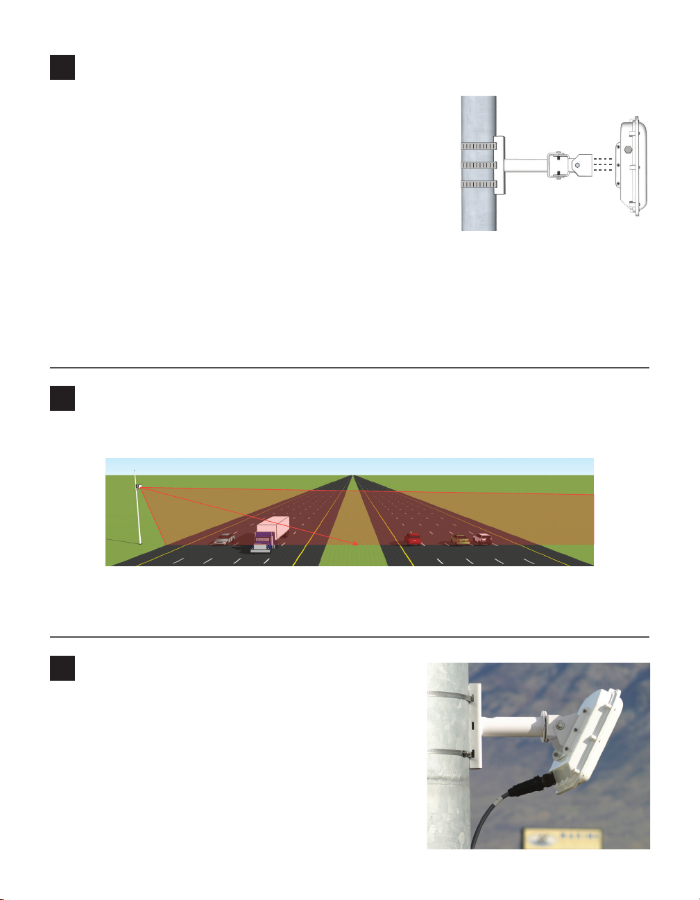
Attach the sensor and mount bracket to the pole
3
Attach the mount bracket to the pole:
1 Insert the stainless steel straps through the slots in the mount
bracket.
2 Position the mount on the pole so that the head of the mount is
pointing towards the middle of the lanes of interest.
3 Tighten the strap screws partway. e sensor alignment will need
to be ne-tuned later, so keep the straps loose enough to be adjustable but tight enough to be secure.
Attach the sensor to the mount bracket:
1 Align the bolts on the sensor’s backplate with the holes in the mount bracket. e connector at the bot-
tom of the unit should be pointing towards the ground.
2 Place the lock washers onto the bolts aer the bolts are in the mount bracket holes.
3 read on the nuts and tighten.
Align the sensor to the roadway
4
1 Tilt the sensor down so that the front is aimed at the center of the detection area.
2 Adjust the side-to-side angle as close to perpendicular to the ow of trac as possible. e side-to-side
alignment will be ne-tuned in step 10 using the SmartSensor Manager HD soware.
Attach the SmartSensor cable
5
1 Tear the tab o the silicon dielectric compound and squeeze
about 25% of it into the connector at the base of the sensor.
Wipe o any excess compound.
2 Insert the cable into the connector and twist clockwise until
you hear it click into place.
3 To avoid undue movement from wind, strap the cable to the
pole or run it through a conduit, but leave a small amount of
slack at the top of the cable to reduce strain.
Page 3

Attach the pole-mount cabinet
6
1 Attach the mounting brackets to the back of the pole-mount box;
thread in the mounting straps.
2 Position the pole-mount box onto the pole and attach the box to
the pole using the mounting straps.
3 Run the sensor/homerun cables through the cable grips on the bot-
tom of the pole-mount box.
Connect surge protection and power
7
SmartSensor HD normally ships with one of two cable types. Newer installations will use the 8-conductor cable, but some installations may still use the 9-conductor cable. e wiring of these cables diers very
slightly. e image below shows the wiring of the 8-conductor cable; below that, the dierences in wiring the 9-conductor cable are explained.
is covers the basics of how to wire the Click 200:
1 Disconnect the Click 200 from the DIN rail.
2 Disconnect the green screw terminals on the appropriate
side of the Click 200 and wire the sensor cable as shown
in the diagram.
3 Connect the Click 200 to the DIN rail.
4 Connect the ground terminal to the DIN rail and the
earth ground wire to the lug bolt on the bottom of the
pole-mount box.
5 Connect the exterior lug bolt to earth ground.
6 Connect 10–30 VDC to the +DC and –DC terminals on
the appropriate side of the Click 200.
Note. e Click 200 has one side marked PROTECTED and
one marked UNPROTECTED; which you use depends on
your installation. If you’re unsure which side to use, consult
the installation designs, Chapter 2 of the SmartSensor HD
User Guide, or Wavetronix Technical Services.
RTS (Orange)
CTS (Brown)
-485 (Blue)
+485 (White)
+DC (Red)
-DC (Black)
RD (Purple)
TD (Yellow)
Drain
Note. If you have a 9-conductor cable, it will have the following wiring dierences:
˽ ere is a gray ground wire that can be plugged into any GND terminal.
˽ Instead of one drain, there are three; they can also be plugged into any GND terminals.
˽ e white +485 wire does not have a blue stripe.
Page 4

Install the SmartSensor Manager HD (SSMHD) software
8
To conrm correct sensor installation and ne-tune sensor alignment, install the SmartSensor Manager HD
(SSMHD) soware using the steps below:
1 Download the setup program from the Wavetronix website, www.wavetronix.com. Go to the Support
tab, select SmartSensor from the drop-down menu, then select SmartSensor HD from the list. Click
the link for SmartSensor Manager HD under the Soware heading.
2 Double-click on the le and follow the steps included in the install wizard.
Make a connection
9
SSMHD allows for three connection types: serial, Internet, and virtual (for
testing and demonstration). You’ll most commonly make a serial connection.
To do this:
1 Make a physical or wireless connection to the sensor. is will likely
involve making a wired or wireless connection to a Click device that has
a communication connection with the sensor—for instance, to a device
that is on the same T-bus as the Click 200 surge protector the sensor is
connected to.
2 Launch SSMHD and click the serial button on the Connect section
of the main menu.
3 Change any necessary settings, such as port or speed.
4 Click Connect.
Complete sensor alignment
10
1 Select Lanes from the main menu, then Conguration.
2 Click on the magnifying glass icon and then click Show Alignment. Adjust
the sensor according to the arrow and the colors shown on the detected
vehicles. Green means the sensor is positioned for optimal performance;
yellow or red means the sensor is NOT correctly aligned with the roadway.
3 Once the sensor is properly aligned, tighten the strap screws the rest of the
way.
For the sensor alignment tool to function properly, trac must be owing
freely. Aer each adjustment of the sensor, several vehicles must pass before the
alignment tool’s output is valid. Also, if the sensor is not already aligned close to
perpendicular to trac, this tool will display a question mark, indicating that the
sensor is too far out of alignment for the tool to function properly.
© 2014 Wavetronix LLC. All rights reserved. Protected by US Pat. Nos. 6,556,916; 6,693,557; 7,426,450; 7,427,930; 7,573,400; 7,889,097; 7,889,098; 7,924,170; 7,991,542; 8,248,272;
8,665,113; and Cdn. Pat. Nos. 2,461,411; 2,434,756; 2,512,689; and Euro. Pat. Nos. 1435036; 1438702; 1611458. Other US and international patents pending. Wavetronix, SmartSensor, Click,
Command and all associated logos are trademarks of Wavetronix LLC. All other product or brand names as they appear are trademarks or registered trademarks of their respective holders. Product specifications are subject to change without notice. This material is provided for informational purposes only; Wavetronix assumes no liability related to its use.
WX-500-0170
 Loading...