

Page 1

Stratum 100
Wireless Ethernet Bridge
Installation
and
Maintenance
Guide
Page 2

Copyright © 1999 Wavespan Corporation. All rights reserved.
No part of this publication (whether in hardcopy or electronic form) may be reproduced or
transmitted, in any form or by any means, electronic, mechanical, photocopying, recording, or
otherwise, without the prior written consent of the publisher. Any information referred to
herein is furnished under license with Wavespan Corporation and may only be used, copied,
transmitted, stored, or printed in accordance with the terms of such license.
This publication and the information herein is furnished AS IS, is subject to change without
notice, and should not be construed as a commitment by Wavespan Corporation. Wavespan
Corporation assumes no responsibility or liability for any errors or inaccuracies, makes no
warranty of any kind (express, implied, or statutory) with respect to this publication, and
expressly disclaims any and all warranties of merchantability, fitness for particular purposes,
and noninfringement of third party rights.
Wavespan is a trademark of Wavespan Corporation. Other brand or product names are the
trademarks or registered trademarks of their respective holders.
FCC Regulatory Compliance
This device complies with Part 15 of the FCC Rules. Operation is subject to the following
two conditions: (1) This device may not cause harmful interference, and (2) this device must
accept any interference received, including interference that may cause undesired operation.
This equipment has been tested and found to comply with the limits for a Class A digital
device pursuant to Part 15 of the FCC Rules. These limits are designed to provide reasonable
protection against harmful interference when the equipment is operated in a commercial
environment. This equipment generates, uses, and can radiate radio frequency energy and, if
not installed and used in accordance with the instruction manuals, may cause harmful
interference to radio communications. Operation of this equipment in a residential area is
likely to cause harmful interference in which case the user will be required to correct the
interference at his own expense.
The following information is for FCC compliance of unlicensed, intentional radiators. This
equipment complies with FCC Regulation 15.407 as relating to point-to-point wireless
communication.
Modifications to this product not expressly approved by Wavespan Corporation could void
the FCC approval and the user’s right to operate the product.
Wavespan Corporation
500 N. Bernardo Avenue
Mountain View, CA 94043
+1 650 919-0190
http://www.wavespan.com
Printed in the United States of America
10 9 8 7 6 5 4 3 2 1 031699
Page 3

Safety Warning
Before aiming the antenna or working near the antenna, read all of this manual and
follow the instructions carefully.
DO NOT STAND IN FRONT OF THE ANTENNA WHILE POWER IS
ON.
Be sure to provide adequate grounding and lightning protection. Do not install the
Outdoor Unit near overhead electrical wires.
This unit is intended for point-to-point operation over an unobstructed line-of-sight path. It is
the responsibility of the installer to ensure the unit is properly installed in compliance with the
FCC’s guidelines for maximum permissible radio frequency exposure outlined in CFR 47
Section 1.1307(b)(1), preventing excess exposure to all persons. The installed radiating
device should be inaccessible to unauthorized personnel. The installed unit should be
positioned to guarantee no direct continuous exposure to people within 5 feet of the antenna.
During installation use caution to avoid excess exposures to directed antenna radiation within
3 feet of the front of the antenna.
The transmit power output from the Stratum 100 is less than 15 milliwatts. However, after the
gain of the standard 18-inch square antenna, the Effective Radiated Power is approximately
5.2 watts. Microwave radiation can cause tissue heating, potentially affecting the eyes,
causing permanent damage to vision.
Page 4

Precautions when Rack Mounting the
Stratum 100
When rack mounting your Stratum 100, you should the following precautions for safety and
to ensure proper operation of the equipment:
The maximum ambient temperature for the Stratum 100 IDU is 50degrees C. Care should be
taken that when installed in a rack, whether closed or open, the ambient temperature within
the rack should not exceed 50 degrees C.
Stratum 100 IDUs have fans and ventilation holes to ensure proper air flow and maintain
correct internal temperature. Do not block the fans or ventilation holes.
When mounting any equipment in racks, you must take into account mechanical loading of
the rack. Heavier equipment should be placed near the bottom of the rack and equipment
should not be mounted in such a way as to cause instability. Special precautions should be
taken with mountings that slide out for easier access to equipment. Such mountings can cause
instability of the rack resulting in unsafe conditions and possible tipping of the rack.
Ensure that the power source, wiring and over-current protection to rack mounted equipment
is rated such that it can support the cumulative load of all equipment. Do not exceed the
capacity of the wiring or over-current protection.
Reliable grounding of the Stratum 100 is required.
The rack should also be grounded. If power distribution strips are used, ensure that they are
properly grounded.
Page 5

Contents
About this Manual.............................................................................................................1
Whom This Manual is Intended For 1
Additional Reading 1
How This Manual Is Organized 1
Conventions 1
Introduction.......................................................................................................................3
Some Definitions 3
Standard Configuration 3
Installation .........................................................................................................................5
Installation Overview 5
Assembling Tools and Cables Before You Begin 6
Step 1. Installing and Mounting the ODUs 7
Step 2. Installing the Cabling from the IDUs to the ODUs 9
Step 3. Installing the IDUs 10
Preliminary Preparation: The Path Survey & Cable Installation 5
Step 1. Installing and Mounting the ODUs 5
Step 2. Installing the Cabling from the IDUs to the ODUs 5
Step 3. Installing the IDUs 5
Step 4. Aiming the Antennas 5
Step 5. Connecting to Ethernet 6
Step 6. Verifying Correct System Operation 6
Step 7. (Optional) Connecting a Modem to the AUX Port 6
Step 8. Connecting to a PBX or other T1 device. 6
For installing the ODUs 6
For the cabling between each IDU and associated ODU unit 6
For installing the IDUs 6
Setting Antenna Polarization 7
Attaching the Antenna Mount 7
Antenna Mast Requirements 7
Attaching Mount On Mast 7
Grounding the ODU and Mast 8
Lightning Protection 8
Routing Cables 9
Attaching the Cables 9
Weatherproofing the Outdoor Connectors 9
Environmental Requirements 10
Unpacking and Installing the Hardware 10
Attaching the Power Cable 10
Accessing the User Interface Software 12
Setting up the Second IDU 16
Stratum 100 Installation and Maintenance Guide Contents •• i
Page 6

Step 4. Aiming the Antennas 17
Modulation Level 17
Transmit (Tx) Power 17
Understanding the Built-in Aiming LED Indicator 17
Aiming the First Antenna 18
Aiming the Second Antenna 18
Verifying the Aim and Path Quality 18
Canceling Antenna Aiming Mode 19
Bringing the Link Up 20
If there are Problems… 21
Step 5. Connecting to Ethernet 22
Connecting the Hardware 22
Setting the Ethernet Parameters 22
Connecting Ethernet to the Other IDU 22
Verifying Ethernet Connectivity 23
Step 6. Verifying Correct System Operation 24
Clearing Old Alarms and Events 24
Checking that Packets are Transmitting 24
Step 7. (Optional) Installing a Modem or other Device on the AUX Port 26
Configuring the Modem Settings for Administrators Dialing In 26
Configuring Dialing Out to Send SNMP Traps 26
Setting PPP Configuration for Other Devices 26
Step 8. Connecting to a PBX 27
Maintaining and Monitoring the Stratum 100.............................................................29
Understanding the LEDs on the Front Panel 29
Connecting to the Stratum 100 29
Using the Console Port 29
Using Telnet and a VT100 Terminal Emulator 31
Using Telnet and a Web Browser 32
Remote Access through the Modem on the AUX Port 33
PPP Access Through the AUX Port 34
Accessing a Stratum 100 From its Remote Companion Stratum 100 (Through the Wireless Link) 35
Using SNMP 36
Dialing Out with Alarms using SNMP 36
Navigating in the VT100 User Interface 38
Moving the Cursor 38
Selecting Menu Choices and Commands 38
Read-Only Fields 38
Editable Fields 38
Toggle Fields 38
Applying Changes 38
Exit to Previous Screen 38
Navigating in the HTML Interface 39
Viewing Alarms and Events 39
Clearing Old Alarms and Events 39
Performance Monitoring 39
Checking that Packets are Going Over the Wireless Link 40
Checking that Packets are Being Bridged to/from the Ethernet Link 41
Checking the Status of the T1 Link 43
Setting Security Parameters 45
Setting Passwords for Access 45
Changing the Automatic Logout Timer 45
Checking Incoming Calls on the AUX Port 46
Adjusting T1 Settings 46
Adjusting the PPP Parameters for Directly Connected Devices on the AUX Port 47
Changing the Communication Settings on the Console Port 47
ii •• Contents Stratum 100 Installation and Maintenance Guide
Page 7

Troubleshooting..............................................................................................................49
Troubleshooting Strategies 49
Diagnosing Problems using the LEDs on the Front Panel 50
Understanding Alarms and Events 50
Viewing Alarms and Events 50
Clearing Old Alarms and Events 51
Understanding the Different Alarm and Event Messages 52
Running Diagnostics 53
Running Diagnostic Tests 53
Checking Software Versions and Configuration 54
Installation Problems 54
Other Common Problems 54
Contacting Technical Support 55
… Through Your Reseller or Dealer 55
… Through Wavespan 55
Appendix A: Technical Specifications ........................................................................57
Index.................................................................................................................................59
Stratum 100 Installation and Maintenance Guide Contents •• iii
Page 8

Page 9

About this Manual
Thank you for purchasing a Wavespan Stratum 100 wireless Ethernet bridge.
Whom This Manual is Intended For
Additional Reading
How This Manual Is Organized
Conventions
Stratum 100 Installation and Maintenance Guide About this Manual •• 1
Page 10

Page 11

Introduction
The Stratum 100 is a wireless Ethernet bridge designed to deliver dedicated full-duplex 100
Mbps connectivity with fiber reliability. The Stratum 100 transports all Ethernet traffic types
in addition to providing connection for two T1 channels.
A standard configuration Stratum 100 link is shipped with a pair of Indoor Units (IDUs) and
Outdoor Units (ODUs). The standard configuration ODUs include integrated 18-inch square
flat antennas and two-axis adjustable antenna mounts. The 18-inch flat antennas will support
a full-reliability link over distances from across the street to up to 5 miles.
Some Definitions
The Stratum 100 consists of two units:
In addition, the IDU and ODU communicate via two multi-mode fibers, one each for transmit
and receive. An additional twisted pair connection is required to supply power from the IDU
to the ODU.
Standard Configuration
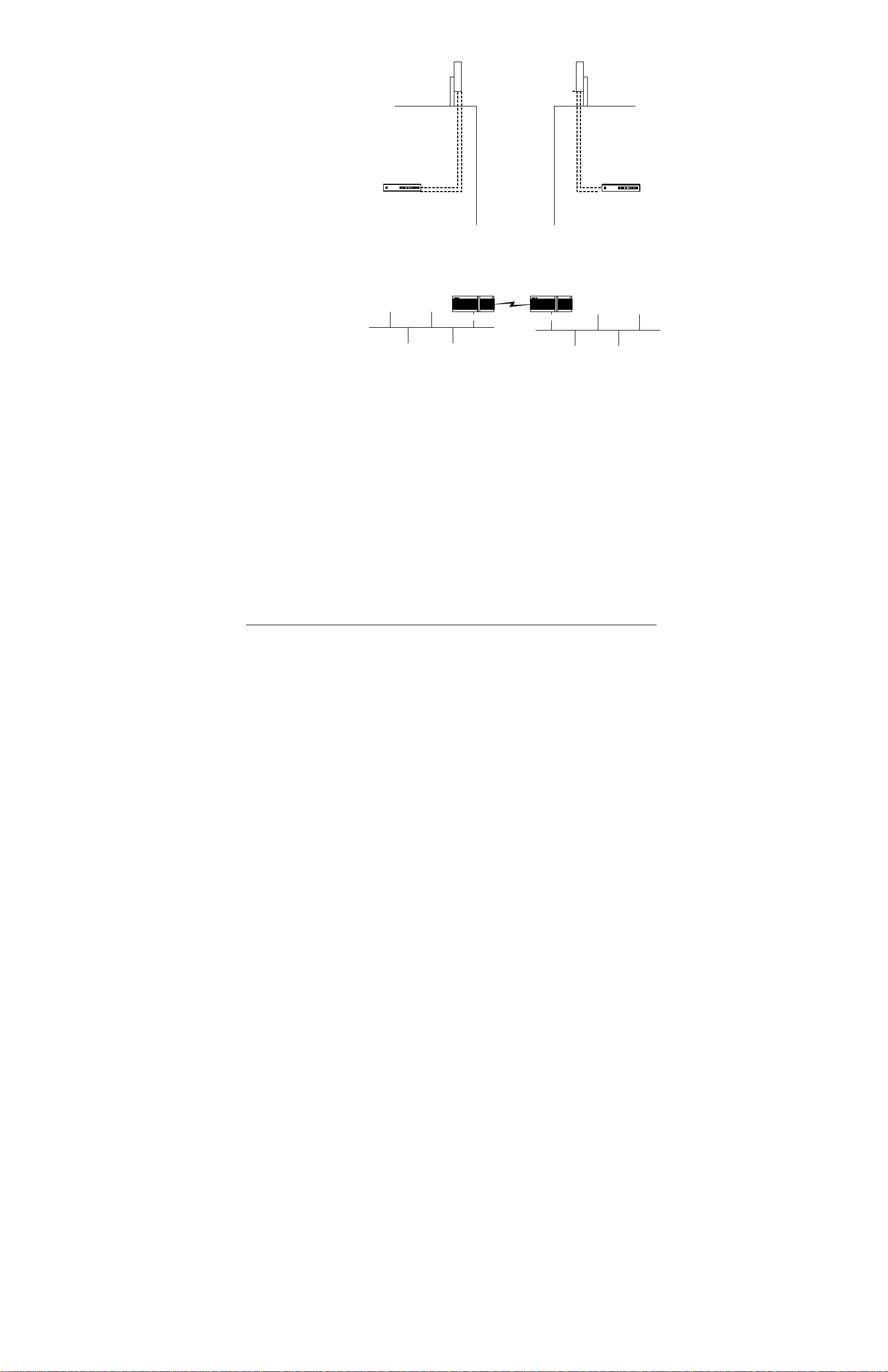
The diagram below shows the standard configuration, which has two buildings, each with
their own roof-mounted ODU and the IDU inside the building bridging the traffic to the
Ethernet.
• The Indoor Unit (IDU) is a rack-mounted unit which contains the electronic
bridging components. The IDU can be located in any convenient climatecontrolled location inside your building.
• The Outdoor Unit (ODU) consists of an antenna integrated with other system
components. The ODU must be mounted within line of sight of another
Stratum 100 (typically on the roof) in order for communications to occur.
Stratum 100 Installation and Maintenance Guide Introduction •• 3
Page 12
Outdoor Unit (ODU)
mounted on pole
power
and
multi-mode fiber
cables
Outdoor Unit (ODU)
mounted on pole
Indoor Unit (IDU)
Indoor Unit (IDU)
Typical system configuration, showing the two ODUs, mounted on the roofs of two adjacent buildings
and the associated IDUs located inside the buildings.
In topological (logical) terms, the Stratum 100 is simply a bridge between two subnets of your
network as shown in the diagram below.
Stratum 100 Stratum 100
LAN subnet in building #1
LAN subnet in building #2
4 •• Introduction Stratum 100 Installation and Maintenance Guide
Page 13

Installation
Installation Overview
The steps required to install the Stratum 100 are described below. The first step requires
engineering experience and knowledge that is beyond the scope of this book.
Preliminary Preparation: The Path Survey & Cable
Installation
Before beginning installation, you must have a path survey completed, including line-of-sight
path planning, antenna supports, and pre-installation preparation. The path survey should also
specify the expected signal strength between the two antennas. The path survey is typically
done by your engineering staff or by your reseller. The process of doing a path survey is
beyond the scope of this book. If you have questions or problems about the path survey,
contact your reseller or Wavespan sales/technical support. The remainder of this manual
assumes that you have completed the path survey and chosen locations for the IDUs and
ODUs.
Step 1. Installing and Mounting the ODUs
As part of your path survey, an appropriate site must be selected for the two ODUs. Typically
each ODU is attached to a pole on the roof, or in some cases, a tower. Installation of the
appropriate pole or tower is not covered in this manual. Instead, installation should be in
accordance with the findings of the Path Survey.
Note that your antenna supports require an earth ground for lightning and static protection.
Step 2. Installing the Cabling from the IDUs to the ODUs
After the ODU location has been chosen, you must run a multi-mode fiber cable and a twisted
pair (DC power) cable from the ODU location to the IDU location.
Step 3. Installing the IDUs
Each IDU must be installed in either a rack or on a tabletop. Unpacking and setting up the
IDU is described in detail below. Each IDU unit requires a controlled environment and an AC
power outlet (3-prong, with ground).
Step 4. Aiming the Antennas
The next step requires you to aim the antennas so that they are correctly aligned and the signal
strength is maximized.
Stratum 100 Installation and Maintenance Guide Installation •• 5
Page 14

Step 5. Connecting to Ethernet
Once the antennas have been correctly aimed, you can connect the IDUs to the network and
allow data transmission to begin.
Step 6. Verifying Correct System Operation
When all of the other steps are complete, you must check that data transmission is occurring
correctly.
Step 7. (Optional) Connecting a Modem to the AUX Port
A modem can be connected to the AUX port to allow remote dial-in management for the
Stratum 100. This is an optional feature.
Step 8. Connecting to a PBX or other T1 device.
The Stratum 100 can be used to provide two high-speed T1 connections between buildings.
These T1 channels can be used to interconnect PBXs, channel banks, video codecs or other T1
devices, channelized or unchannelized. The T1 interface is industry standard DSX-1.
Assembling Tools and Cables Before You Begin
You will need the following tools before beginning the installation:
For installing the ODUs
• ½” socket and/or open-end wrenches
• Philips screwdriver
For the cabling between each IDU and associated ODU
unit
• 62.5 micron fiber, multi-mode 850 nanometer cable (for data transmission)
Two cables are required.
• Twisted pair cable (for DC power connection) 2 pairs of 18 AWG
Note that the cable length will be different for each IDU/ODU pair, depending on the distance
between them.
For installing the IDUs
• 100Base-TX or 10Base-T cable suitable for connecting the Stratum 100 to your
Ethernet network.
OR
• Media Independent Interface Adpater suitable for connecting the Stratum 100
to your Ethernet network via another media such as fiber.
• PC or laptop running HyperTerminal, or an equivalent VT-100 emulator. The
PC or laptop must have a serial port with DB-9 male connector or adapter to
accept the DB-9 female connector on the supplied serial cable.
6 •• Installation Stratum 100 Installation and Maintenance Guide
Page 15

Step 1. Installing and Mounting the ODUs
The instructions below describe how to assemble and mount a single IDU. You must repeat
the installation for each ODU.
Remove the ODU, pre-assembled Antenna Mount and Accessory Kit from their shipping
cartons. Save all packing materials in case you need them later.
Using the foam packing material to protect the painted surfaces of the antenna, carefully
place the ODU on a tabletop with the antenna facing down. The paint provides an important
extra barrier to UV from sunlight.
Set aside the accessory kit. You will use this hardware to attach the antenna mount to the
ODU, and to attach the complete ODU to a supporting mast.
Setting Antenna Polarization
Antenna polarization must be the same at both ends of any link. For single links, vertical
polarization is a good default. There is no performance difference. For multiple links
located on the same rooftop, alternating the antenna polarization of independent links is
recommended.
If the coaxial connectors are facing down the antennas operate with vertical polarization.
Connectors facing right or left produces horizontal polarization.
Attaching the Antenna Mount
Slightly loosen the six 5/16-18 bolts on the Antenna Mount slotted elevation arms and angle
brackets so that they can be positioned for the next step.
Position the Antenna Mount on the ODU so that the angle bracket attached to the two
elevation arms is along the edge with the coax connectors (vertical polarization). The other
angle bracket is bolted to the opposite edge.
Use 5/16-20x1” hex-head bolts, flat washers and lock nuts at three corners of the ODU as
shown. The next step describes the corner with the ground wire.
Locate the ground wire, which has #10 and 5/16” lugs on its ends.
Place a 1x5/16” hex head bolt through the 5/16” lug of the ground wire, followed by a 5/16”
flat washer. Place this bolt, ground lug and flat washer through the angle bracket and ODU
corner hole nearest to the #10 ground stud on the back plate of the ODU. Secure with a flat
washer and lock nut as shown.
Tighten all four corner bolts securely.
Place a #10 flat washer over the #10 ground stud, followed by the ground wire and a #10 lock
washer. Tighten this nut, but do not over-torque.
Note: Avoid scratching the painted surfaces of the ODU during antenna mount installation.
Antenna Mast Requirements
The ODU must be mounted on a tubular steel or aluminum mast 1.9 to 3.9 inches in
diameter using the remaining hardware supplied in the antenna mount accessory kit.
The mast must be stable, not able to bend or rotate under extreme weather conditions, and
must provide a line-of-sight path to the other end of your link.
Attaching Mount On Mast
This section illustrates installation on a vertical mast. A horizontal support is perfectly
acceptable.
Cut the length of rubber collar material (using a sharp knife) so that it wraps around your mast
with a small gap (.10 - .25 inch) between the ends.
Select the proper size hose clamp and install the rubber collar securely on the mast. This
collar is used to hold the weight of the ODU during installation and antenna alignment.
Stratum 100 Installation and Maintenance Guide Installation •• 7
Page 16

For masts 1.9 to 2.5 inches in diameter use 3.5 inch long hex-head bolts for each yoke. For
masts 2.5 to 3.9 inches in diameter use the 4.5 inch long hex-head bolts.
Use a safety rope, or second person to hold the ODU in position on the mast, resting on the
rubber collar as shown. Install the top clamping yoke first. Install the bottom yoke last.
Note: Be careful not to drop the ODU. The weather seals protecting the antenna and microwave
transceiver can be damaged.
Visually aim the antenna as precisely as possible in azimuth and elevation. Use a map and
compass to set the correct direction. Tighten both yokes and elevation arms securely until you
are ready for antenna aiming.
Position mount on clamp, install top yoke first
Install bottom yoke last
Grounding the ODU and Mast
In Section 7.1 you connected the ODU’s ground stud to the antenna mount, which in turn must
be grounded through the metallic mast. These important ground connections provide a short
circuit path for static that could build up on the ODU, potentially damaging the microwave
transceiver or degrading performance. This protection depends on the metallic mast or
antenna support being properly connected to an earth ground.
A building’s electrical system ground is typically not a good earth ground because it can have
high currents flowing through it that result from an imbalance in the distribution of the singlephase load throughout a building. Ground loops can result if two pieces of equipment are
grounded to the electrical system ground and if there is a voltage difference between the
ground points. For electrical protection it is important that the Stratum 100 Indoor and ODUs
are grounded to an earth ground that does not have a voltage difference between the Indoor
and ODUs.
Lightning Protection
Damage to your Stratum 100 Indoor or ODUs caused directly or indirectly by lightning
is not covered under the manufacturer’s warranty.
If your ODU is located where nearby or direct lightning strikes are possible, especially on the
top of a tall building, a lightning rod and grounding system installed by a licensed
professional are highly recommended. In addition, the use of lightning arrestors in the two
coaxial cables (located in-line at the cable entry point to the building or at the rear of the IDU)
with an earth ground is highly recommended. Wavespan and its authorized resellers can
recommend suppliers of suitable coaxial lightning arrestors with Type-N connectors and
ground posts.
The purpose of in-line lightning arrestors in the coaxial cables is to protect the IDU from high
voltages induced by nearby lightning or a direct lightning strike at the ODU. The ideal
location for in-line lightning arrestors would be at the point where the coaxial cables enter the
building. This involves separate cables from the ODU to the point of entry, and additional
cables from there to the IDU. The next best approach is to locate in-line lightning arrestors at
the rear of the IDU, with a separate heavy-guage (#10 or #8) earth ground running directly
from the lightning arrestors to a proper grounding system.
8 •• Installation Stratum 100 Installation and Maintenance Guide
Page 17

Step 2. Installing the Cabling from the IDUs to the ODUs
Routing Cables
Label both ends of each cable, one cable for Tx (transmit) and one for Rx (receive), before
you route them.
Run cables through existing roof vents if possible. Weatherproof the entry point and protect
the cable from sharp metal edges. Secure the cable to prevent abrasion due to movement in
the wind.
Attaching the Cables
Be sure that the IDU power switch is OFF before connecting the cables to the ODU.
Attach the Tx and Rx cables to their respective connectors on the Indoor and ODUs. Hand-
tighten all connectors firmly.
Weatherproofing the Outdoor Connectors
Wrap the outdoor Tx and Rx coaxial connectors using CoaxSeal or similar weatherproofing
tape to create a sealed moisture barrier around the connectors after they are tightened on the
ODU.
Stratum 100 Installation and Maintenance Guide Installation •• 9
Page 18

Step 3. Installing the IDUs
Environmental Requirements
The IDU requires a protected environment with its temperature maintained between 00 and 55
C (320 – 1310 F), and less than 95% relative humidity, non-condensing. The environment
should be free from extremes in temperature, dust, humidity, shock, vibration and RF fields to
ensure the IDU’s operation within published specifications.
Because the IDUs have cooling fans, they can be rack mounted or stacked without spaces
between them. A clearance of at least one inch on both sides is required for ventilation.
Be sure that the ventilating perforations on the sides and rear (near connectors) are not
blocked by cables or other equipment. Better ventilation, resulting from air space around the
IDU, improves equipment reliability.
Unpacking and Installing the Hardware
1. Remove the IDU from its shipping carton.
2. Locate and set aside the accessory kit (with cables and mounting hardware)
supplied in this carton. Save all packing materials in case you need them later.
3. Read the FCC Regulatory Compliance notice and Safety Warnings at the
beginning of this manual.
IDU Accessory Kit Packing List
The IDU Kit contains
• rack mounting brackets and hardware,
• rubber mounting feet, (for tabletop use only)
• AC line cord,
• RJ-45 console cable (straight-through CAT-5 cable),
• RJ-45-to-DB-9 console adapter, and
• clamp-on ferrite filter for the 10Base-T cable.
Rack Mounting the IDU
Three sets of rack mounting bracket hole patterns allow the IDU to be mounted with its
connectors facing the rear or front. A center pattern also allows the IDU to be mounted in
center rail racks or on the surface of a wall if the brackets are installed facing down as shown.
Attach the two rack mounting brackets on each side of the IDU as shown. Use four #832x1/2” Pan Head screws and #8 lock washers (under the screw head) for each bracket.
Tighten the screws securely.
Mount the IDU in an equipment rack near your networking equipment (hub, server, switch, or
router) to which it will be connected. Use two #12-24x3/4” screws in each rack bracket to
mount the unit.
Tabletop Installation of the IDU
If you are installing the unit on a tabletop, attach the (4) self-adhesive rubber feet to the
bottom of the unit near the corners. The rubber feet are not used if you rack mount the
IDU.
0
Attaching the Power Cable
Make sure the ON/OFF switch is OFF or “0”. Attach the AC power cord to the rear of the
unit and plug it into a grounded AC outlet. Do not turn the power on until you have
connected the management console (described below).
10 •• Installation Stratum 100 Installation and Maintenance Guide
Page 19

Stratum 100 Installation and Maintenance Guide Installation •• 11
Page 20

Accessing the User Interface Software
Connecting the Management Console
Note: A straight-through data cable is provided for connecting your PC or laptop as a setup or
management console.
Locate the data cable supplied in the accessory kit. Attach one end to the RJ-45 CONSOLE
port connector on the rear of the Indoor Unit.
Install the RJ-45 to DB-9 adapter on the other end of this console cable.
Connect the DB-9 adapter to your PC or laptop COM port.
Note: It is important to use the DB-9 adapter supplied by Wavespan, even if you use a DB-9
to DB-25 adapter to match your PC or laptop COM port. The adapter supplied by Wavespan
converts the RJ-45 CONSOLE port wiring to standard COM port wiring.
To perform the initial setup of the Stratum 100, you must connect a PC system running a VT100 terminal emulator such as the HyperTerminal utility. The communications settings for
the console terminal must be:
• 9600 baud
• 8 bits
• no parity
• 1 stop bit
• no flow control
Turning on the IDU
After you have finished mounting the IDU, connect the AC power cable to the back of the
unit and turn on the power switch. Once the PC is attached to the console port and the power
is turned on, you will see the following introductory screen:
Stratum 100 Wireless Broadband Communication System
Software Version 00.01c
Copyright (c) 1996 - 1998
Access Level: [? ]
Password: [? ]
Entering the Password
When it is configured at the factory, the Stratum 100 is preset to have the following:
Access Level: superuser
Password: wavespan
After you enter these two fields, the Main Menu screen will appear as shown below.
12 •• Installation Stratum 100 Installation and Maintenance Guide
Page 21

---------------------------- Stratum 100 Main Menu --------------------------- System Status: STBY - NOT CONNECTED - ALARM NEW [ Alarms & Events.. ]
System Date/Time: 1999-02-19,11:06:18.0
------- Local -------- ------ Remote -------
Device Name: DEFAULT ?
Device Location: DEFAULT ?
Link Description: DEFAULT ?
IDU Serial Number: 00000 ?
ODU Serial Number: ? ?
Ethernet Address: 00:60:c1:00:01:35 ?
IP Address: 192.168.10.134 ?
Alarms: DISABLED ?
----------------------------------------------------------------------------- [ System Admin.. ] [ Reports.. ] [ Utilities.. ] [ Diagnostics.. ]
[ Remote ] [ Remote Exit ] [ Logout ]
-------------------------------------------------------------------------------
Specifying Initial Settings
From the main menu, use the arrow key to move to the System Admin field. Press Enter to
go to the system administration menu as shown below.
---------------------------- System Administration ------------------------ System Status: STBY - NOT CONNECTED - ALARM NEW [ Alarms & Events.. ]
System Date/Time: [1999-02-19,11:16:01.0]
System Administrator: [DEFAULT ]
Device Name: [DEFAULT ]
Device Location: [DEFAULT ]
Link Description: [DEFAULT ]
Circuit Identifier: [DEFAULT ]
Alarms: [Disabled]
--------------------------------------------------------------------------- Link Up/Down: [Down]
--------------------------------------------------------------------------- [ Link Setup.. ] [ Passwords.. ] [ Console Port.. ] [ SNMP.. ]
[ Ethernet Config.. ] [ T1 Config.. ] [ Modem Config.. ] [ PPP.. ]
[ ^Apply ] [ ^OK ] [ ^Cancel ]
-----------------------------------------------------------------------------
Enter correct values on the fields on this screen.
To update a field, use the down arrow key to move to that field. Type the desired value
and press Enter. Then press the down arrow to move to the next field.
After all changes are made, press the down arrow until
is highlighted, and press Enter to accept and save your changes.
[ ^Apply ]
If you do not choose [ ^Apply ] your changes will not be saved.
First, set the correct date and time. This time should be very accurate as it will be used as a
time stamp for the bridging functions of the Stratum 100.
The text fields displayed on this screen that are informational only. However it is useful to
have correct values set here.
Stratum 100 Installation and Maintenance Guide Installation •• 13
Page 22

• The System Administrator field is a text string that contains the name of the
administrator responsible for this Stratum 100 unit.
• The Device Name and Device Location simply specify text strings that
identify this IDU/ODU combination.
• The Link Description and Circuit Identifier describe the location and circuit
of the wireless link.
Finally, use the arrow key to go to the Alarms field. Press the space bar to toggle the value to
Enabled.
Finally, press the down arrow until [^ Apply ] is selected. Press Enter to apply and save
your changes.
Alternately, you can press Ctrl A from anywhere on the screen to save your changes.
14 •• Installation Stratum 100 Installation and Maintenance Guide
Page 23

Setting Antenna Aiming Mode
Use the down arrow key to move to Link Setup and press Enter to go to the link setup menu.
----------------------------------- Link Set-Up ------------------------------ System Status: AIMING - NOT CONNECTED - ALARM NEW [ Alarms & Events.. ]
----------------------------- Link Parameters ---------------------
Transmit Power Level: [Low ]
Link ID: [DEFAULT ]
Antenna Aiming: [Enabled ]
[ ^Apply ] [ ^OK ] [ ^Cancel ]
------------------------------------------------------------------------------
Specify the Transmit PowerLevel by using the space bar to toggle between low and high
power. Typically low power is used for links spanning less than 800 feet and high power is
used for links over longer distances.
Enter a 10-digit value for the Link ID field. This value will be used as a security hash code,
and it must be the same value for both IDUs.
Set the Antenna Aiming field to be Enabled.
Press Ctrl A to apply your changes.
Use the down arrow to move to the Ok field and press Enter to leave this menu.
Stratum 100 Installation and Maintenance Guide Installation •• 15
Page 24

Setting the IP Address (Optional)
If you wish to access the IDU through Telnet for remote management, you must assign an IP
address. If you will not be accessing the unit remotely, you can skip this step.
From the System Administration Menu, use the down arrow to go to Ethernet Config and
press Enter to go to the Ethernet Configuration menu.
If you wish to manage the system remotely via SNMP, you must set an IP address.
------------------------------ Ethernet Configuration ------------------------ System Status: OPERATE - CONNECTED - OK [ Alarms & Events.. ]
--------------------------- Physical Interface ------------------------------- Auto Negotiation: [Disabled]
Speed: [10 Mb ]
Duplex: [Half-Duplex]
Interface Type: [RJ45]
--------------------------- TCP/IP ------------------------------------------- IP Address: [192.168.3.202 ]
IP Subnet Mask: [255.255.255.0 ]
Default Gateway: [192.168.3.1 ]
--------------------------- Spanning Tree------------------------------------- Spanning Tree State: [Enabled ]
Hello Time: [2 ] Bridge Priority: [32768]
Forward Delay: [15 ] Port Cost: [100 ]
Max Age: [20 ] Port Priority: [128 ]
[ ^Apply ] [ ^OK ] [ ^Cancel ]
-------------------------------------------------------------------------------
Use the down arrow to go the TCP/IP section of the screen and enter the IP Address, IP
Subnet Mask, and Default Gateway (if needed).
Press Ctrl A to apply your changes. Use the down arrow to go to OK and press Enter to leave
this menu.
You have now specified all of the basic configuration parameters for the IDU and you can
unplug the computer from the console port.
Setting up the Second IDU
The second IDU unit should be installed and configured in exactly the same way. Note that
you must use the same Link ID for the second IDU.
16 •• Installation Stratum 100 Installation and Maintenance Guide
Page 25

Step 4. Aiming the Antennas
Modulation Level
The Wavespan 5800 operates using a default modulation level of 256-QAM for links in the
range of 330 feet to 5 miles. This provides maximum throughput with full link reliability.
For longer link distances a Wavespan 5800 system with the standard 18 inch flat antennas can
be configured in software to operate using lower modulation levels, operating with slightly
reduced throughput over longer distances with full reliability. Refer to the table at the bottom
of this page that describes the relationship between modulation level, range, and throughput.
An optional configuration of the Outdoor Unit is available, without the standard 18-inch flat
antenna, that provides a Type-N antenna connector for use with higher gain standard parabolic
antennas. The use of optional parabolic antennas can support 10 Mbits/sec full-duplex
throughput over distances up to 30 miles or more.
Transmit (Tx) Power
Set the same transmitter power output for both Master and Slave units in accordance
with the table below. Find the distance closest to the actual range of your link and set the
Tx Power parameter by typing the value shown, then press ENTER. If your link distance is
greater than 5 miles, and your system is equipped with the standard 18-inch antennas, it will
be necessary to set the modulation level lower than 256-QAM.
The positive Tx Power values must be typed without a “+” sign. The negative values must
be typed as “-7”, using the minus sign followed by the single digit power level, without a
space in-between.
If your link is shorter than 2 miles, it is important that you set the transmit power (Tx PWR)
level of both ends as described. Excess transmit power for short link distances may cause
unnecessary interference to other links, and overload of the receivers in your link, which can
degrade the bit-error-rate performance, causing some dropped packets.
Understanding the Built-in Aiming LED Indicator
Note: The Outdoor Unit has a high-intensity LED that indicates signal acquisition and strength.
Aiming LED: Indications
1. On (solid) means the Outdoor Unit is being supplied power but is not
configured in aiming mode.
2. One long flash every 5 seconds means that the local unit is in aiming mode but
is not able to lock on the aiming signal from the other end. The Master is
transmitting, the Slave is not.
3. Three quick flashes per second means the local unit is locked on the aiming
signal but is not aimed in the peak region (within 6 dB of the highest signal
detected so far). Both ends are transmitting.
4. Fifteen quick flashes per second means that the local unit is locked on the
aiming signal and is aimed in the peak region (within 6 dB of the highest
signal detected so far). A sampling circuit ‘remembers’ the highest level seen
as you scan the antenna from side to side and top to bottom, allowing you to
record and find the ‘edges’ of the peak region.
5. One quick flash every 10 seconds means the unit is in normal operation, not
in the aiming mode.
6. Off (solid) means the unit is off or has a cable fault.
A (0 – 5 VDC) aiming voltage is also available on the BNC connector in the center.
The peak signal value is stored as you sweep side-to-side. The LED guides you back to the
correct peak value.
Stratum 100 Installation and Maintenance Guide Installation •• 17
Page 26

Aiming Technique
Slowly (over about 5 seconds) sweep the Outdoor Unit in azimuth (side to side) covering a
90-degree arc, and in elevation covering a 30-degree arc (centered on the line-of-sight path).
This will allow the peak sampling circuit to record the highest level in the center of the
peak region. The link may go in and out of lock as you sweep; it will re-lock within 3
seconds. The peak signal level will be retained in memory as long as you are in aiming
mode. The flash rate will be 15 per second in the narrow peak signal region, and 3 per
second in the surrounding in-lock region. The peak signal region will be roughly 10
degrees wide with the standard 18-inch square antennas. The flashing pattern will guide you
back to the peak.
By capturing the peak level one axis at a time, you can see the left and right or upper and
lower edges of the peak. Position the antenna in the geometric center of the peak region
in both azimuth and elevation for optimum link performance.
Note: Aiming is easiest if you have two people with cell phones for coordination, one at each
antenna.
Aiming the First Antenna
1. Loosen the Bolts
You will need a ½-inch open-end or socket wrench for aiming. Make sure that the bolts on
the upper and lower yokes have been loosened just enough to be able to rotate the antenna on
the mast. The rubber collar supports the weight of the Outdoor Unit during aiming.
Antenna mount side view with rubber collar
Note: Re-read Antenna Aiming Technique to be sure you can ‘see’ the edges of the peak region.
2. Set Azimuth in Center of Peak Signal
Using the antenna aiming technique described in Section 13.2, watch the LED to find the
edges of the peak signal while rotating the antenna 90 degrees in azimuth (side to side).
Position the antenna in the center of the peak region. Tighten the upper and lower yokes
securely on the mast.
Note: To position the antenna exactly in the center of the peak signal region you can use a permanent
marker to identify the edges of the peak on the lower yoke or on the mast, and on the elevation arms for
the step below.
3. Set Elevation in Center of Peak Signal
Loosen the two bolts holding the elevation arms at the angle bracket and the two bolts
through the slots of both arms. Using the antenna aiming technique described above, watch
the LED to find the peak signal while raising and lowering the antenna in elevation. Set
the antenna in the center of the peak region. Securely tighten the four bolts at both ends of
the elevation arms. Also securely tighten the two bolts on the upper angle bracket.
Aiming the Second Antenna
Repeat exactly this same process for the other end of your link.
The first unit’s antenna typically does not need to be re-aimed after the second is aimed. You
can easily re-peak the first unit after the master end is aimed.
Verifying the Aim and Path Quality
It is important to check signal strength and link performance before using the link for ‘live’
network traffic. This will ensure that your line-of-sight path and antenna aiming are
satisfactory. To check signal strength, connect to the user interface of either Stratum 100 unit
(as described starting on page 12).
18 •• Installation Stratum 100 Installation and Maintenance Guide
Page 27

Receive Signal Strength Indicator (RSSI)
The Report screen shows the RSSI value which represents the average signal level on all
clear channels, and is updated once per second during normal operation. To see the Reports
screen, choose Reports from the main menu.
------------------------------------ Reports --------------------------------- System Status: STBY - NOT CONNECTED - ALARM [ Alarms & Events.. ]
System Name: DEFAULT
System Uptime: 1999-03-11,13:34:59.0
IDU Temperature: 0
ODU Temperature: 0
RSSI: 0
[ T1 Channel 1 Status ]
[ T1 Channel 2 Status ]
[ Modem Status ]
[ LAN Status ]
[ Session Status ]
[ RF Link Status ]
[ ^Cancel ]
------------------------------------------------------------------------------
MODULATION MIN. RSSI TYP. RANGE
256-QAM -63 dBm 5 miles
64-QAM -66 dBm 8 miles
16-QAM -69 dBm 11 miles
QPSK -74 dBm 18 miles
Typical RSSI values for clear paths
For a properly installed link at 5 miles, and a Tx Power output of +8 dBm, the typical RSSI
value should be above –63 dBm (a smaller negative number in the range of –55 to –63 dBm)
for 256-QAM operation. For lower level modulation the minimum RSSI values are shown
above. A Wavespan Stratum 100 link, with the standard 18-inch antenna or an optional
higher gain parabolic antenna, must be set up to meet the minimum RSSI values in this
table in order to deliver specified reliability in all weather conditions.
If the RSSI value is more than 3 dB lower than the Aiming value or the values in the
table above, one of the following is likely: (a.) the link has been set up over a distance that is
too long, (b.) the antennas are not both aimed correctly, or (c.) there are obstacles blocking or
too close to the line of sight path (inadequate Fresnel Zone clearance). It may operate
satisfactorily, but will have lower fade margins than are ideal.
To ensure the lowest possible bit error rate and overall link reliability, the RSSI should not be
operated higher than –55 dBm (it must be between –55 and the Minimum RSSI shown in the
table above). If your link’s RSSI is higher than –55 dBm, set the transmit power of both ends
lower (keeping both ends the same) until the level is –55 dBm on the average.
(18 inch antenna)
Canceling Antenna Aiming Mode
In the Link Setup screen, use the down arrow to move the highlight bar to Antenna Aiming
Mode. Press the space bar to toggle the mode from Enabled to Disabled aiming mode.
Choose [ ^Apply ] to save your change, and then choose [ ^OK ] to return to the System
Administration screen.
Stratum 100 Installation and Maintenance Guide Installation •• 19
Page 28

Bringing the Link Up
From System Administration, use the down arrow to move to the Link Up/Down field and
then press the space bar to toggle its value to Up.
Choose [ ^Apply ] to save your change, and then choose [ ^OK ] to return to the Main
Menu screen.
20 •• Installation Stratum 100 Installation and Maintenance Guide
Page 29

If there are Problems…
Stratum 100 Installation and Maintenance Guide Installation •• 21
Page 30

Step 5. Connecting to Ethernet
Connecting the Hardware
Note: The MII port and 10Base-T port cannot both be used at the same time. Also, the AUI
port is only half duplex.
Attach a data cable (not provided) to the 100Base-TX port on the Indoor Unit. . For a hub or
switch, use a straight through data cable. For a router use a crossover cable.
Install the snap-on ferrite filter as close as possible to the rear panel RJ-45 connector as
shown. This snap-on filter is required on the 10Base-T cable for FCC certification of the
Indoor Unit.
Plug the other end of this data cable into your network.
Setting the Ethernet Parameters
From the System Administration Menu, use the down arrow to go to Ethernet Config and
press Enter to go to the Ethernet Configuration menu.
------------------------------ Ethernet Configuration ------------------------ System Status: OPERATE - CONNECTED - OK [ Alarms & Events.. ]
--------------------------- Physical Interface ------------------------------- Auto Negotiation: [Disabled]
Speed: [10 Mb ]
Duplex: [Half-Duplex]
Interface Type: [RJ45]
--------------------------- TCP/IP ------------------------------------------- IP Address: [192.168.3.202 ]
IP Subnet Mask: [255.255.255.0 ]
Default Gateway: [192.168.3.1 ]
--------------------------- Spanning Tree------------------------------------- Spanning Tree State: [Enabled ]
Hello Time: [2 ] Bridge Priority: [32768]
Forward Delay: [15 ] Port Cost: [100 ]
Max Age: [20 ] Port Priority: [128 ]
[ ^Apply ] [ ^OK ] [ ^Cancel ]
-------------------------------------------------------------------------------
Use the down arrow to go the Physical Interface section of the screen. You must either
enable Auto Negotiation or specifically set the speed and duplex. (These fields are toggled
by pressing the space bar.) You must also specify the Interface Type (RJ45 or MII).
The IP address information in the TCP/IP section is only required if you will be accessing the
unit remotely via Telnet.
If you wish to use spanning tree, you can set those parameters now.
Press Ctrl A to save (apply) your changes. Use the down arrow to go to OK and press Enter
to leave this menu.
Connecting Ethernet to the Other IDU
Connect the Ethernet cable to the second IDU in the same manner as the first one. Use the
console port to set the Ethernet parameters.
22 •• Installation Stratum 100 Installation and Maintenance Guide
Page 31

Verifying Ethernet Connectivity
From the Main Menu, use the down arrow to highlight the [ Diagnostics ] selection and
------------------------------ Diagnostics ----------------------------------- System Status: STBY - NOT CONNECTED - ALARM NEW [ Alarms & Events.. ]
------------------------------ Ping Test ------------------------------------- Target IP Addr: [0.0.0.0 ] Target:
Timeout (seconds): [0 ] Count: 0
[ Start_Ping ] [ Stop_Ping ]
------------------------------ Loopback Tests -------------------------------- T1 Ch 1: [DISABLE]
T1 Ch 2: [DISABLE]
System: [DISABLE]
[ Apply_Loopback ]
------------------------------ BER Tests ------------------------------------- Channel: [T1_Ch1] Test: [Mark ]
Time: 0 Errors: 0 Rate: 0
[ Start_BER ] [ Stop_BER ] [ Reset_Counters ]
------------------------------ Other Tests ----------------------------------- [ View Power-On-Self-Test Results ] [ ^Cancel ]
-------------------------------------------------------------------------------
press Enter to go to the Diagnostics menu.
To verify Ethernet connectivity, enter the IP address of the remote Stratum 100 in the Target
IP Addr: field. Set the Timeout value with the number of seconds to perform the ping test.
Pings will be sent once per second for the specified time.
Use the down arrow to highlight the [ Start_Ping ] choice and press Enter to begin the test.
As the test proceeds, the Target field will be updated to show if the target responded. This
field will display Not Found if the target does not respond. If the target responds correctly,
this field will display Alive.
Stratum 100 Installation and Maintenance Guide Installation •• 23
Page 32

Step 6. Verifying Correct System Operation
To verify that the system is operating correctly, connect a PC system to the serial console port
of one of the IDUs and log in to the system as described starting on page 12.
Clearing Old Alarms and Events
While the system was being configured, a number of spurious alarms were generated. It will
be easier to see if the system is working correctly if those alarms are deleted. To do this, from
the Main Menu, use the down arrow to move to the Alarms and Events.. item. Press Enter to
------------------------------ Alarms & Event Log ---------------------------- System Status: OPERATE - NOT CONNECTED - ALARM
Time Stamp Description Type
-----------------------------------------------------------------------------1999-03-11,13:35:07.0 ODU Link Failure A
1999-03-11,13:35:03.0 Warm Start E
1999-03-11,08:32:43.0 System Diagnostic Ended E
1999-03-11,08:20:04.0 System Diagnostic Started E
1999-03-11,08:19:58.0 System Diagnostic Ended E
1999-03-11,08:19:16.0 System Diagnostic Started E
1999-03-11,08:19:13.0 System Diagnostic Ended E
1999-03-11,08:18:58.0 System Diagnostic Started E
1999-03-11,08:18:51.0 System Diagnostic Ended E
1999-03-11,08:18:39.0 System Diagnostic Started E
1999-03-11,08:18:37.0 System Diagnostic Ended E
1999-03-11,08:18:11.0 System Diagnostic Started E
1999-03-11,08:18:04.0 System Diagnostic Ended E
1999-03-11,08:17:47.0 System Diagnostic Started E
----------------------------------------------------------------------------- [ Clear All Alarms ] [ Clear All Events ] Mode: [WRAP WHEN FULL]
[ Page Up ] [ Page Down ] [ Home ] [ End ] [ ^Apply ] [ ^OK ] [ ^Cancel ]
-------------------------------------------------------------------------------
go to the Alarms menu.
Use the down arrow to go to the Clear All Alarms item. Press Enter.
Use the down arrow to go to the Clear All Events item. Press Enter.
Use the down arrow to go to OK and press Enter to leave the screen.
Checking that Packets are Transmitting
From the Main Menu, use the down arrow to move to the Reports.. selection. Press Enter to
display the Reports Menu.
24 •• Installation Stratum 100 Installation and Maintenance Guide
Page 33

------------------------------------ Reports --------------------------------- System Status: OPERATE - NOT CONNECTED - ALARM NEW [ Alarms & Events.. ]
System Name: DEFAULT
System Uptime: 1999-03-11,13:34:59.0
IDU Temperature: 0
ODU Temperature: 0
RSSI: 0
[ T1 Channel 1 Status ]
[ T1 Channel 2 Status ]
[ Modem Status ]
[ LAN Status ]
[ Session Status ]
[ RF Link Status ]
[ ^Cancel ]
------------------------------------------------------------------------------
Checking that Packets are Going Over the Wireless Link
Use the down arrow to select RF Link Status. Press Enter to display that report. When the
link is working correctly, the Rx Corrupt Packets and Rx Overruns should both be zero.
When packets are being transmitted, the Tx Packet Count and the Rx Packet Count fields
will increase as data is transmitted across the wireless link. To verify that these counts are
increasing, wait for a few seconds and then press Ctrl U to update the counters.
Use the down arrow to move to Cancel and press Enter to leave this report screen.
Checking that Packets are Being Bridged to/from the Ethernet Link
From the Reports Menu, use the down arrow to go to LAN Status and press Enter to display
that report.
The Rx counter shows the number of packets that were received from the Ethernet link and
bridged. The Tx counter shows the number of packets that were received from the wireless
link and transmitted to the Ethernet link.
Note that Ethernet packets and RF packets are not the same thing, because of the different
transmission requirements of the two media.
Use the down arrow to move to Cancel and press Enter to leave this report screen.
Stratum 100 Installation and Maintenance Guide Installation •• 25
Page 34

Step 7. (Optional) Installing a Modem or other Device on the
AUX Port
The AUX port on the back of the Stratum 100 is a standard RJ45 connector. You may
connect any standard modem to that port. You can then manage the Stratum 100 by dialing
directly into the modem.
To do this, simply connect a standard RJ45 serial cable to your modem.
Configuring the Modem Settings for Administrators
Dialing In
System Admin
Modem Config
----------------------------- Modem Configuration -----------------------------
System Status: STBY - NOT CONNECTED - ALARM [ Alarms & Events.. ]
Dial String 1: [AT ]
Dial String 2: [AT ]
Init String 1: [AT ]
Init String 2: [AT ]
Dial Out Time Interval: [60 ]
Dial Out Attempts: [5 ]
-------------------------- Port Parameters -----------------------------------
Baud Rate: [9600 ]
Stop Bits: [1]
Parity: [None]
Handshake: [None ]
Data Bits: [8]
[ ^Apply ] [ ^OK ] [ ^Cancel ]
------------------------------------------------------------------------------
Configuring Dialing Out to Send SNMP Traps
Setting PPP Configuration for Other Devices
26 •• Installation Stratum 100 Installation and Maintenance Guide
Page 35

Step 8. Connecting to a PBX
Stratum 100 Installation and Maintenance Guide Installation •• 27
Page 36

Page 37

Maintaining and Monitoring the
Stratum 100
Understanding the LEDs on the Front Panel
On the front panel of the Stratum 100 are LEDs that provide a quick verification that the unit
is operating correctly. The LEDs are also discussed in more detail in the Troubleshooting
section, beginning on page xx.
LED Name Normal Display: … which Indicates:
Status off No alarms or events.
Test off No testing currently in progress.
RF Link on (solid green) RF link to companion Stratum 100 is active and available.
LAN Link on (solid green) LAN is available. This applies only if the RJ45 link is being used.
LAN Tx blinking green Each blink indicates a packet received from the RF link and sent to
LAN Rx blinking green Each blink indicates a packet received from the Ethernet.
Dx on (solid green) Full duplex. Applies to RJ45 link only; if using MII, check the MII
on (solid amber) Half duplex. Applies to RJ45 link only; if using MII, check the MII
10/100 on (solid green) 100 Mbps operation
on (solid amber) 10 Mbps operation
T1 CH1 green Channel receiving ok; if the T1 channel is disabled, this LED will
T1 CH2 green Channel receiving ok; if the T1 channel is disabled, this LED will
If using MII, check the MII adapter for status LEDs.
the Ethernet.
adapter for status LEDs.
adapter for status LEDs.
If no data is being received, then this LED will be solid amber.
be off.
be off.
Connecting to the Stratum 100
Using the Console Port
The RJ45 connector on the back of the Stratum 100 labeled CONSOLE allows you to
connect any standard RS232C terminal emulator that supports VT100. Of course this method
Stratum 100 Installation and Maintenance Guide Maintaining and Monitoring the Stratum 100 •• 29
Page 38

requires physical access to one of the Stratum 100 IDU units (both units, if the wireless link is
not available).
Note: It is important to use the DB-9 adapter supplied by Wavespan, even if you use a DB-9
to DB-25 adapter to match your PC or laptop COM port. The adapter supplied by Wavespan
converts the RJ-45 CONSOLE port wiring to standard COM port wiring.
The simplest way to access the console is to connect a PC system running a VT-100 terminal
emulator such as the HyperTerminal utility. The communications settings for the console
terminal must be:
• 9600 baud
• 8 bits
• no parity
• 1 stop bit
• no flow control
Once the PC is attached to the console port and the power is turned on, you will see the
following introductory screen:
Stratum 100 Wireless Broadband Communication System
Software Version 00.01c
Copyright (c) 1996 - 1998
Access Level: [? ]
Password: [? ]
Entering the Password
When it is configured at the factory, the Stratum 100 is preset to have the following:
Access Level: superuser
Password: wavespan
After you enter these two fields, the Main Menu screen will appear and you can monitor and
manage the Stratum 100 as described later in this manual.
30 •• Maintaining and Monitoring the Stratum 100 Stratum 100 Installation and Maintenance Guide
Page 39

Using Telnet and a VT100 Terminal Emulator
If you have configured an IP address for your Stratum 100, you can access it using Telnet. To
do this, simply use your standard Telnet utility and specify the IP address of the Stratum 100.
Once the Telnet connection has been established, you will be able to see the following
introductory screen:
Stratum 100 Wireless Broadband Communication System
Software Version 00.01c
Copyright (c) 1996 - 1998
Access Level: [? ]
Password: [? ]
Entering the Password
When it is configured at the factory, the Stratum 100 is preset to have the following:
Access Level: superuser
Password: wavespan
---------------------------- Stratum 100 Main Menu --------------------------- System Status: STBY - NOT CONNECTED - ALARM NEW [ Alarms & Events.. ]
System Date/Time: 1999-02-19,11:06:18.0
------- Local -------- ------ Remote -------
Device Name: DEFAULT ?
Device Location: DEFAULT ?
Link Description: DEFAULT ?
IDU Serial Number: 00000 ?
ODU Serial Number: ? ?
Ethernet Address: 00:60:c1:00:01:35 ?
IP Address: 192.168.10.134 ?
Alarms: DISABLED ?
----------------------------------------------------------------------------- [ System Admin.. ] [ Reports.. ] [ Utilities.. ] [ Diagnostics.. ]
[ Remote ] [ Remote Exit ] [ Logout ]
-------------------------------------------------------------------------------
After you enter these two fields, the Main Menu screen will appear as shown below.
Stratum 100 Installation and Maintenance Guide Maintaining and Monitoring the Stratum 100 •• 31
Page 40

Using Telnet and a Web Browser
You can also access the Stratum 100 interface using Telnet and a Web browser. Simply
specify the IP address of the Stratum 100 in the Address field of your browser, and the
HTML interface will appear:
<<screen shot>>
32 •• Maintaining and Monitoring the Stratum 100 Stratum 100 Installation and Maintenance Guide
Page 41

Remote Access through the Modem on the AUX Port
If you have connected an optional modem to the AUX port, you can access the Stratum 100
remotely by dialing in to the modem. Once the dial connection is established, you will see the
opening screen:
Stratum 100 Wireless Broadband Communication System
Software Version 00.01c
Copyright (c) 1996 - 1998
Access Level: [? ]
Password: [? ]
Entering the Password
When it is configured at the factory, the Stratum 100 is preset to have the following:
Access Level: superuser
Password: wavespan
---------------------------- Stratum 100 Main Menu --------------------------- System Status: STBY - NOT CONNECTED - ALARM NEW [ Alarms & Events.. ]
System Date/Time: 1999-02-19,11:06:18.0
------- Local -------- ------ Remote -------
Device Name: DEFAULT ?
Device Location: DEFAULT ?
Link Description: DEFAULT ?
IDU Serial Number: 00000 ?
ODU Serial Number: ? ?
Ethernet Address: 00:60:c1:00:01:35 ?
IP Address: 192.168.10.134 ?
Alarms: DISABLED ?
----------------------------------------------------------------------------- [ System Admin.. ] [ Reports.. ] [ Utilities.. ] [ Diagnostics.. ]
[ Remote ] [ Remote Exit ] [ Logout ]
-------------------------------------------------------------------------------
After you enter these two fields, the Main Menu screen will appear as shown below.
Stratum 100 Installation and Maintenance Guide Maintaining and Monitoring the Stratum 100 •• 33
Page 42

PPP Access Through the AUX Port
The AUX port can also be used for direct access (similar to the CONSOLE port). The AUX
port uses PPP and it is typically connected to a terminal server or PBX.
To set the PPP parameters of the AUX port choose System Admin and then select PPP.. from
---------------------------- PPP Configuration ------------------------------- System Status: STBY - NOT CONNECTED - ALARM NEW [ Alarms & Events.. ]
------------------------------ PPP Options ---------------------------------- Connection Types: [NONE ]
Remote IP: [127.0.0.1 ] User: [default ]
Authentication: [PAP ]
[ Dial Out ] [ Hangup ]
----------------------------- Secrets File ---------------------------------- [ ]
[ ]
[ ]
[ ]
[ ]
-------------------------------- Options ------------------------------------ [ ]
[ ]
Link Status:
[ ^Apply ] [ ^OK ] [ ^Cancel ]
------------------------------------------------------------------------------
the System Administration screen.
<<description of fields>>
34 •• Maintaining and Monitoring the Stratum 100 Stratum 100 Installation and Maintenance Guide
Page 43

Accessing a Stratum 100 From its Remote Companion
Stratum 100 (Through the Wireless Link)
If you are connected to a Stratum 100 IDU, and the wireless link is up, you can log in to the
companion Stratum 100 by choosing the System Admin.. command from the main menu.
From the System Administration screen, select Remote to log on to the remote IDU.
You will see the opening screen
Stratum 100 Wireless Broadband Communication System
Software Version 00.01c
Copyright (c) 1996 - 1998
Access Level: [? ]
Password: [? ]
Entering the Password
When it is configured at the factory, the Stratum 100 is preset to have the following:
Access Level: superuser
Password: wavespan
---------------------------- Stratum 100 Main Menu --------------------------- System Status: STBY - NOT CONNECTED - ALARM NEW [ Alarms & Events.. ]
System Date/Time: 1999-02-19,11:06:18.0
------- Local -------- ------ Remote -------
Device Name: DEFAULT ?
Device Location: DEFAULT ?
Link Description: DEFAULT ?
IDU Serial Number: 00000 ?
ODU Serial Number: ? ?
Ethernet Address: 00:60:c1:00:01:35 ?
IP Address: 192.168.10.134 ?
Alarms: DISABLED ?
----------------------------------------------------------------------------- [ System Admin.. ] [ Reports.. ] [ Utilities.. ] [ Diagnostics.. ]
[ Remote ] [ Remote Exit ] [ Logout ]
-------------------------------------------------------------------------------
After you enter these two fields, the Main Menu screen will appear as shown below.
After you choose Remote Exit you will be disconnected and you will return to the main menu
of the local Stratum 100 IDU.
Stratum 100 Installation and Maintenance Guide Maintaining and Monitoring the Stratum 100 •• 35
Page 44

Using SNMP
Once the Stratum 100 is installed, you can use SNMP to manage and monitor it. To enable
traps by your SNMP manager, you must first access the Stratum 100 through some other
method (e.g. through the console port) and configure SNMP access.
To enable SNMP management, select System Admin.. from the main menu. Then choose
SNMP from the System Administration screen.
------------------------------- SNMP Management -------------------------- System Status: STBY - NOT CONNECTED - ALARM [ Alarms & Events.. ]
Read Community String: [public ]
Write Community String: [private ]
Trap Community String: [snmptrap ]
SNMP Trap Destinations IP Addr Screening
---------------------- --------------------- [0.0.0.0 ] [0.0.0.0 ]
[0.0.0.0 ] [0.0.0.0 ]
[0.0.0.0 ] [0.0.0.0 ]
[0.0.0.0 ] [0.0.0.0 ]
[0.0.0.0 ] [0.0.0.0 ]
SNMP Agent: [Disabled]
IP Screening: [Disabled]
[ ^Apply ] [ ^OK ] [ ^Cancel ]
-------------------------------------------------------------------------------
Enter the desired values on the SNMP Management screen. Then choose the SNMP Agent
field and use the space bar to toggle the value to Enabled.
Choose Apply to save your changes and then select OK to close the screen.
Dialing Out with Alarms using SNMP
You can also configure the AUX port to be used as a dial out line to send SNMP traps to a
specified location. To do this, choose System Admin from the main menu. From the System
Administration screen, select Modem Config to set up the dial out information.
36 •• Maintaining and Monitoring the Stratum 100 Stratum 100 Installation and Maintenance Guide
Page 45

----------------------------- Modem Configuration -----------------------------
System Status: STBY - NOT CONNECTED - ALARM NEW [ Alarms & Events.. ]
Dial String 1: [AT ]
Dial String 2: [AT ]
Init String 1: [AT ]
Init String 2: [AT ]
Dial Out Time Interval: [60 ]
Dial Out Attempts: [5 ]
-------------------------- Port Parameters -----------------------------------
Baud Rate: [9600 ]
Stop Bits: [1]
Parity: [None]
Handshake: [None ]
Data Bits: [8]
[ ^Apply ] [ ^OK ] [ ^Cancel ]
<<description of fields>>
Stratum 100 Installation and Maintenance Guide Maintaining and Monitoring the Stratum 100 •• 37
Page 46

Navigating in the VT100 User Interface
The user interface uses standard VT100 conventions.
Moving the Cursor
The UP/DOWN arrow keys move the cursor to the next or previous selection (see Accessing
the User Interface Console). The TAB key also advances the cursor to the next selection.
Selecting Menu Choices and Commands
Selectable items are shown in square brackets. For example,
[ Modem Status ]
Selectable items that also have a keyboard are shown with the
Read-Only Fields
These fields display information that cannot be edited in the current screen. They might be
edited in another screen. The cursor will not highlight Read-Only fields.
Editable Fields
You may type any alpha or numeric characters in Editable Fields. The backspace key can be
used in these fields. You must press ENTER before going on, to register the new contents.
Toggle Fields
Use the space bar to select the fixed choices. (You do not need to press Enter after setting a
toggle field).
Applying Changes
Type CTRL A (or move cursor to ^Apply and press ENTER) to apply changed settings
without exiting this screen. Changes only take effect if you apply them. Type CTRL O (or
^OK) to apply changes and exit to the previous screen. Some changes in the Link Setup
screen will automatically reboot the system when you apply them (you will be prompted first).
Exit to Previous Screen
Type CTRL C to EXIT the display of this screen and go back to the previous screen. If you
had not applied any changes, they will not be retained after exiting the current screen.
38 •• Maintaining and Monitoring the Stratum 100 Stratum 100 Installation and Maintenance Guide
Page 47

Navigating in the HTML Interface
The HTML interface uses different conventions for navigating through the screens.
Viewing Alarms and Events
Clearing Old Alarms and Events
While the system was being configured, a number of spurious alarms were generated. It will
be easier to see if the system is working correctly if those alarms are deleted. To do this, from
the Main Menu, use the down arrow to move to the Alarms and Events.. item. Press Enter to
------------------------------ Alarms & Event Log ---------------------------- System Status: OPERATE - NOT CONNECTED - ALARM
Time Stamp Description Type
-----------------------------------------------------------------------------1999-03-11,13:35:07.0 ODU Link Failure A
1999-03-11,13:35:03.0 Warm Start E
1999-03-11,08:32:43.0 System Diagnostic Ended E
1999-03-11,08:20:04.0 System Diagnostic Started E
1999-03-11,08:19:58.0 System Diagnostic Ended E
1999-03-11,08:19:16.0 System Diagnostic Started E
1999-03-11,08:19:13.0 System Diagnostic Ended E
1999-03-11,08:18:58.0 System Diagnostic Started E
1999-03-11,08:18:51.0 System Diagnostic Ended E
1999-03-11,08:18:39.0 System Diagnostic Started E
1999-03-11,08:18:37.0 System Diagnostic Ended E
1999-03-11,08:18:11.0 System Diagnostic Started E
1999-03-11,08:18:04.0 System Diagnostic Ended E
1999-03-11,08:17:47.0 System Diagnostic Started E
----------------------------------------------------------------------------- [ Clear All Alarms ] [ Clear All Events ] Mode: [WRAP WHEN FULL]
[ Page Up ] [ Page Down ] [ Home ] [ End ] [ ^Apply ] [ ^OK ] [ ^Cancel ]
-------------------------------------------------------------------------------
go to the Alarms menu.
Use the down arrow to go to the Clear All Alarms item. Press Enter.
Use the down arrow to go to the Clear All Events item. Press Enter.
Use the down arrow to go to OK and press Enter to leave the screen.
Performance Monitoring
A variety of reports and statistics are provided to help you check system performance and
manage the Stratum 100.
From the Main Menu, use the down arrow to move to the Reports.. selection. Press Enter to
display the Reports Menu.
Stratum 100 Installation and Maintenance Guide Maintaining and Monitoring the Stratum 100 •• 39
Page 48

------------------------------------ Reports --------------------------------- System Status: OPERATE - NOT CONNECTED - ALARM NEW [ Alarms & Events.. ]
System Name: DEFAULT
System Uptime: 1999-03-11,13:34:59.0
IDU Temperature: 0
ODU Temperature: 0
RSSI: 0
[ T1 Channel 1 Status ]
[ T1 Channel 2 Status ]
[ Modem Status ]
[ LAN Status ]
[ Session Status ]
[ RF Link Status ]
[ ^Cancel ]
------------------------------------------------------------------------------
Checking that Packets are Going Over the Wireless Link
--------------------------------- RF Link Status -----------------------------
System Status: STBY - NOT CONNECTED - ALARM [ Alarms & Events.. ]
----- Local ----- ----- Remote ---- Tx Pkt Count: 763 ?
Tx Byte Count: 48832 ?
Rx Pkt Count: 0 ?
Rx Byte Count: 0 ?
Rx Bcast: 0 ?
Rx Mcast: 0 ?
Rx Corrupt Packets: 0 ?
Rx Overruns: 0 ?
----------------------------------------------------------------------------- [ RF Pkt Interval ] [ RF Error Interval ]
Start Time: 1999-03-15,10:43:52.0 [ ^Update ] [ Clear ] [ ^Cancel ]
------------------------------------------------------------------------------
Use the down arrow to select RF Link Status. Press Enter to display that report.
When the link is working correctly, the Rx Corrupt Packets and Rx Overruns should both
be zero.
When packets are being transmitted, the Tx Packet Count and the Rx Packet Count fields
will increase as data is transmitted across the wireless link. To verify that these counts are
increasing, wait for a few seconds and then press Ctrl U to update the counters.
Choosing RF Pkt Interval will display a screen that shows packet intervals. <<??>>
40 •• Maintaining and Monitoring the Stratum 100 Stratum 100 Installation and Maintenance Guide
Page 49

---------------------------- RF Packet Intervals -----------------------------
System Status: STBY - NOT CONNECTED - ALARM [ Alarms & Events.. ]
Local: Current Interval 04:45 Remote: Current Interval 04:45
--------------------------------- --------------------------------- TxPkt RxPkt Brdcast TxPkt RxPkt Brdcast
00:00 0 0 0 ? ? ?
00:15 0 0 0 ? ? ?
00:30 0 0 0 ? ? ?
00:45 0 0 0 ? ? ?
01:00 0 0 0 ? ? ?
01:15 0 0 0 ? ? ?
01:30 0 0 0 ? ? ?
01:45 0 0 0 ? ? ?
02:00 0 0 0 ? ? ?
02:15 0 0 0 ? ? ?
02:30 0 0 0 ? ? ?
02:45 0 0 0 ? ? ?
03:00 0 0 0 ? ? ?
03:15 0 0 0 ? ? ?
------------------------------------------------------------------------------ [ Page Up ] [ Page Down ] [ Home ] [ End ] [ ^Update ] [ ^Cancel ]
-------------------------------------------------------------------------------
-------------------------------- Error Intervals -----------------------------
System Status: STBY - NOT CONNECTED - ALARM [ Alarms & Events.. ]
Local: Current Interval 04:45 Remote: Current Interval 04:45
--------------------------------- --------------------------------- RxCorrpt RxOvruns RxCorrpt RxOvruns
00:00 0 0 ? ?
00:15 0 0 ? ?
00:30 0 0 ? ?
00:45 0 0 ? ?
01:00 0 0 ? ?
01:15 0 0 ? ?
01:30 0 0 ? ?
01:45 0 0 ? ?
02:00 0 0 ? ?
02:15 0 0 ? ?
02:30 0 0 ? ?
02:45 0 0 ? ?
03:00 0 0 ? ?
03:15 0 0 ? ?
------------------------------------------------------------------------------ [ Page Up ] [ Page Down ] [ Home ] [ End ] [ ^Update ] [ ^Cancel ]
-------------------------------------------------------------------------------
Choosing RF Error Interval will display a screen that shows error intervals. <<??>>
Use the down arrow to move to Cancel and press Enter to leave this report screen.
Checking that Packets are Being Bridged to/from the
Ethernet Link
From the Reports Menu, use the down arrow to go to LAN Status and press Enter to display
that report.
Stratum 100 Installation and Maintenance Guide Maintaining and Monitoring the Stratum 100 •• 41
Page 50

---------------------------------- LAN Status ---------------------------------
System Status: STBY - NOT CONNECTED - ALARM [ Alarms & Events.. ]
----- Local ----- ----- Remote ---- Tx Pkt Count: 30302 ?
Rx Pkt Count: 0 ?
Rx Bcast: 0 ?
Rx Mcast: 0 ?
Tx Discarded Pkt: 0 ?
Tx Deferred : 0 ?
Tx Errored : 3 ?
Tx Frames Lost: 0 ?
Collisions : 3 ?
Rx Discarded Pkt: 0 ?
Rx Bad CRC : 0 ?
Rx Oversize : 0 ?
Rx Jabber : 0 ?
Rx Alignment Errors: 0 ?
------------------------------------------------------------------------------ Link: READY Auto-Neg: DISABLED Speed: 100 MB Duplex: FULL-DUPLEX
[ LAN Pkt Intvls ] [ Tx Error Intvls ] [ Rx Error Intvls ]
-------------1999-03-15,10:43:52.0 --------[ ^Update ]-[ Clear ]-[ ^Cancel ]--
The Rx counter shows the number of packets that were received from the Ethernet link and
bridged. The Tx counter shows the number of packets that were received from the wireless
link and transmitted to the Ethernet link.
Note that Ethernet packets and RF packets are not the same thing, because of the different
transmission requirements of the two media.
Use the down arrow to move to Cancel and press Enter to leave this report screen.
LAN Pkt Intvls
---------------------------- LAN Packet Intervals -----------------------------
System Status: STBY - NOT CONNECTED - ALARM [ Alarms & Events.. ]
Local: Current Interval 05:00 Remote: Current Interval 05:00
--------------------------------- -------------------------------- TxPkt RxPkt Brdcast TxPkt RxPkt Brdcast
00:00 75 0 0 ? ? ?
00:15 75 0 0 ? ? ?
00:30 75 0 0 ? ? ?
00:45 75 0 0 ? ? ?
01:00 75 0 0 ? ? ?
01:15 75 0 0 ? ? ?
01:30 75 0 0 ? ? ?
01:45 75 0 0 ? ? ?
02:00 75 0 0 ? ? ?
02:15 75 0 0 ? ? ?
02:30 75 0 0 ? ? ?
02:45 75 0 0 ? ? ?
03:00 75 0 0 ? ? ?
03:15 75 0 0 ? ? ?
------------------------------------------------------------------------------ [ Page Up ] [ Page Down ] [ Home ] [ End ] [ ^Update ] [ ^Cancel ]
-------------------------------------------------------------------------------
Tx Error Intvls
42 •• Maintaining and Monitoring the Stratum 100 Stratum 100 Installation and Maintenance Guide
Page 51

------------------------------- Tx Error Intervals ----------------------------
System Status: STBY - NOT CONNECTED - ALARM [ Alarms & Events.. ]
Local: Current Interval 05:00 Remote: Current Interval 05:00
--------------------------------- --------------------------------- TxDrp TxErd TxLost TxDef Coll TxDrp TxErd TxLost TxDef Coll
00:00 0 0 0 0 0 ? ? ? ? ?
00:15 0 0 0 0 0 ? ? ? ? ?
00:30 0 0 0 0 0 ? ? ? ? ?
00:45 0 0 0 0 0 ? ? ? ? ?
01:00 0 0 0 0 0 ? ? ? ? ?
01:15 0 0 0 0 0 ? ? ? ? ?
01:30 0 0 0 0 0 ? ? ? ? ?
01:45 0 0 0 0 0 ? ? ? ? ?
02:00 0 0 0 0 0 ? ? ? ? ?
02:15 0 0 0 0 0 ? ? ? ? ?
02:30 0 0 0 0 0 ? ? ? ? ?
02:45 0 0 0 0 0 ? ? ? ? ?
03:00 0 0 0 0 0 ? ? ? ? ?
03:15 0 0 0 0 0 ? ? ? ? ?
------------------------------------------------------------------------------ [ Page Up ] [ Page Down ] [ Home ] [ End ] [ ^Update ] [ ^Cancel ]
-------------------------------------------------------------------------------
Rx Error Intvls
------------------------------- Rx Error Intervals ----------------------------
System Status: STBY - NOT CONNECTED - ALARM [ Alarms & Events.. ]
Local: Current Interval 05:00 Remote: Current Interval 05:00
--------------------------------- --------------------------------- RxDrp RxCRC RxGnt RxJab RxAlg RxDrp RxCRC RxGnt RxJab RxAlg
00:00 0 0 0 0 0 ? ? ? ? ?
00:15 0 0 0 0 0 ? ? ? ? ?
00:30 0 0 0 0 0 ? ? ? ? ?
00:45 0 0 0 0 0 ? ? ? ? ?
01:00 0 0 0 0 0 ? ? ? ? ?
01:15 0 0 0 0 0 ? ? ? ? ?
01:30 0 0 0 0 0 ? ? ? ? ?
01:45 0 0 0 0 0 ? ? ? ? ?
02:00 0 0 0 0 0 ? ? ? ? ?
02:15 0 0 0 0 0 ? ? ? ? ?
02:30 0 0 0 0 0 ? ? ? ? ?
02:45 0 0 0 0 0 ? ? ? ? ?
03:00 0 0 0 0 0 ? ? ? ? ?
03:15 0 0 0 0 0 ? ? ? ? ?
------------------------------------------------------------------------------ [ Page Up ] [ Page Down ] [ Home ] [ End ] [ ^Update ] [ ^Cancel ]
-------------------------------------------------------------------------------
Checking the Status of the T1 Link
Reports
T1 Channel 1 Status / T1 Channel 2 Status
Stratum 100 Installation and Maintenance Guide Maintaining and Monitoring the Stratum 100 •• 43
Page 52

------------------------------ T1 Channel 1 Status ----------------------------
System Status: STBY - NOT CONNECTED - ALARM [ Alarms & Events.. ]
Channel 1 Alarm Status: NO ALARM
---- Local ---- ---- Remote --- Errored Seconds: 0 ?
Severely Errored Seconds: 0 ?
Severely Errored Framing Seconds: 0 ?
Unavailable Seconds: 0 ?
Line Errored Seconds: 0 ?
Burst Errored Seconds: 0 ?
Degraded Minutes: 0 ?
% AS 0 ?
% EFS 0 ?
% ES 0 ?
% SES 0 ?
% DM 0 ?
% BES 0 ?
[ T1 Channel 1 Intervals ] [ T1 Channel 1 Statistics ]
-------------1999-03-15,10:43:52.0 --------[ ^Update ]-[ Clear ]-[ ^Cancel ]-
T1 Channel 1 intervals
---------------------------- T1 Channel 1 Intervals --------------------------
System Status: STBY - NOT CONNECTED - ALARM [ Alarms & Events.. ]
Local: Current Interval 04:45 Remote: Current Interval 04:45
--------------------------------- --------------------------------- ES SES SEFS US BES DM LES ES SES SEFS US BES DM LES
00:00 0 0 0 0 0 0 0 ? ? ? ? ? ? ?
00:15 0 0 0 0 0 0 0 ? ? ? ? ? ? ?
00:30 0 0 0 0 0 0 0 ? ? ? ? ? ? ?
00:45 0 0 0 0 0 0 0 ? ? ? ? ? ? ?
01:00 0 0 0 0 0 0 0 ? ? ? ? ? ? ?
01:15 0 0 0 0 0 0 0 ? ? ? ? ? ? ?
01:30 0 0 0 0 0 0 0 ? ? ? ? ? ? ?
01:45 0 0 0 0 0 0 0 ? ? ? ? ? ? ?
02:00 0 0 0 0 0 0 0 ? ? ? ? ? ? ?
02:15 0 0 0 0 0 0 0 ? ? ? ? ? ? ?
02:30 0 0 0 0 0 0 0 ? ? ? ? ? ? ?
02:45 0 0 0 0 0 0 0 ? ? ? ? ? ? ?
03:00 0 0 0 0 0 0 0 ? ? ? ? ? ? ?
03:15 0 0 0 0 0 0 0 ? ? ? ? ? ? ?
------------------------------------------------------------------------------ [ Page Up ] [ Page Down ] [ Home ] [ End ] [ ^Update ] [ ^Cancel ]
-------------------------------------------------------------------------------
T1 Channel 1 Statistics
44 •• Maintaining and Monitoring the Stratum 100 Stratum 100 Installation and Maintenance Guide
Page 53

-------------------------- T1 Channel 1 Statistics --------------------------
System Status: STBY - NOT CONNECTED - ALARM [ Alarms & Events.. ]
Local: Current Interval 04:45 Remote: Current Interval 04:45
--------------------------------- -------------------------------- %AS %EFS %ES %SES %DM %BES %AS %EFS %ES %SES %DM %BES
00:00 0 0 0 0 0 0 ? ? ? ? ? ?
00:15 0 0 0 0 0 0 ? ? ? ? ? ?
00:30 0 0 0 0 0 0 ? ? ? ? ? ?
00:45 0 0 0 0 0 0 ? ? ? ? ? ?
01:00 0 0 0 0 0 0 ? ? ? ? ? ?
01:15 0 0 0 0 0 0 ? ? ? ? ? ?
01:30 0 0 0 0 0 0 ? ? ? ? ? ?
01:45 0 0 0 0 0 0 ? ? ? ? ? ?
02:00 0 0 0 0 0 0 ? ? ? ? ? ?
02:15 0 0 0 0 0 0 ? ? ? ? ? ?
02:30 0 0 0 0 0 0 ? ? ? ? ? ?
02:45 0 0 0 0 0 0 ? ? ? ? ? ?
03:00 0 0 0 0 0 0 ? ? ? ? ? ?
03:15 0 0 0 0 0 0 ? ? ? ? ? ?
------------------------------------------------------------------------------ [ Page Up ] [ Page Down ] [ Home ] [ End ] [ ^Update ] [ ^Cancel ]
-------------------------------------------------------------------------------
Setting Security Parameters
Setting Passwords for Access
System Admin
Passwords..
---------------------------- WS5800 System Passwords -------------------------
System Status: STBY - NOT CONNECTED - ALARM [ Alarms & Events.. ]
---- User ID ---- ---- Password ----
SuperUser: [wavespan ]
Maintenance: [ ]
Operator: [wavespan ]
User: [wavespan ]
[ ^Apply ] [ ^OK ] [ ^Cancel ]
------------------------------------------------------------------------------
Changing the Automatic Logout Timer
By default, you will be logged out after 30 minutes of inactivity.
To change this … <<Susan, I couldn’t find this on any of the current screens.>>
Stratum 100 Installation and Maintenance Guide Maintaining and Monitoring the Stratum 100 •• 45
Page 54

Checking Incoming Calls on the AUX Port
Reports
Modem Status
--------------------------------- Modem Status --------------------------------
System Status: STBY - NOT CONNECTED - ALARM [ Alarms & Events.. ]
---- Local ---- ---- Remote ----
Incoming Call Count: 0 ?
Outgoing Call Count: 0 ?
Unsuccessful Incoming Call Count: 0 ?
Unsuccessful Outgoing Call Count: 0 ?
Incoming Connect Time: 00:00:00 ?
Outgoing Connect Time: 00:00:00 ?
[ Zero Stats ]
Start Time: 1999-03-11,13:35:01.0 [ ^Update ] [ ^Cancel ]
------------------------------------------------------------------------------
Zeroing the Stats
Looking at Session Status
Reports
Session Status
----------------------------------- Sessions ----------------------------------
System Status: STBY - NOT CONNECTED - ALARM [ Alarms & Events.. ]
Connection Type Client IP Address Access Level Login Time
--------------- ----------------- ------------ -------------------- [*RS-232 N/A SUPERUSER 1999-03-15,15:09:25.0 ]
[ ]
[ ]
[ ^Cancel ]
-------------------------------------------------------------------------------
Adjusting T1 Settings
System Admin
T1 Config
46 •• Maintaining and Monitoring the Stratum 100 Stratum 100 Installation and Maintenance Guide
Page 55

------------------------------- T1 Configuration ------------------------------
System Status: STBY - NOT CONNECTED - ALARM [ Alarms & Events.. ]
Channel 1 Enable: [Disabled]
Channel 2 Enable: [Disabled]
Channel 1 Software Key: [NO KEY ]
Channel 2 Software Key: [NO KEY ]
Channel 1 Framing Mode: [ESF]
Channel 2 Framing Mode: [ESF]
Channel 1 Line Coding Format: [B8ZS]
Channel 2 Line Coding Format: [B8ZS]
[ ^Apply ] [ ^OK ] [ ^Cancel ]
------------------------------------------------------------------------------
Adjusting the PPP Parameters for Directly Connected
Devices on the AUX Port
System Admin
PPP..
---------------------------- PPP Configuration ------------------------------- System Status: STBY - NOT CONNECTED - ALARM [ Alarms & Events.. ]
------------------------------ PPP Options ---------------------------------- Connection Types: [NONE ]
Remote IP: [127.0.0.1 ] User: [default ]
Authentication: [PAP ]
[ Dial Out ] [ Hangup ]
----------------------------- Secrets File ---------------------------------- [ ]
[ ]
[ ]
[ ]
[ ]
-------------------------------- Options ------------------------------------ [ ]
[ ]
Link Status:
[ ^Apply ] [ ^OK ] [ ^Cancel ]
Changing the Communication Settings on the Console
Port
Stratum 100 Installation and Maintenance Guide Maintaining and Monitoring the Stratum 100 •• 47
Page 56

System Admin
Console Port..
--------------------------- Console Port Configuration ----------------------- System Status: STBY - NOT CONNECTED - ALARM [ Alarms & Events.. ]
-------------------------- Port Parameters ---------------------------------- Baud Rate: [9600 ]
Stop Bits: [1]
Parity: [None]
Handshake: [None ]
Data Bits: [8] Auto Logout (min): [30 ]
-----------------------------------------------------------------------------
[ ^Apply ] [ ^OK ] [ ^Cancel ]
------------------------------------------------------------------------------
48 •• Maintaining and Monitoring the Stratum 100 Stratum 100 Installation and Maintenance Guide
Page 57

Troubleshooting
Troubleshooting Strategies
To troubleshoot problems with the Stratum 100, do the following steps to isolate the location
of the problem:
1. Check the LEDs on both IDU units
2. Check the current alarms and events for both IDU units
3. Look at the reports and status info in the Reports menu for both IDU units
4.
<<Is this approach useful? Suggestions for steps to follow? –HH>>
Stratum 100 Installation and Maintenance Guide Troubleshooting •• 49
Page 58

Diagnosing Problems using the LEDs on the Front Panel
On the front panel of the Stratum 100 are LEDs that provide important status information.
LED
Name
Status off No alarms or events. on (solid red) Pending alarms; alarms can be
Test off No testing currently in progress. on (solid amber) Antenna Aiming mode, or
RF Link on (solid green) RF link to companion Stratum
LAN Link on (solid green) LAN is available. This applies
LAN Tx blinking green Each blink indicates a packet
LAN Rx blinking green Each blink indicates a packet
Dx on (solid green) Full duplex. Applies to RJ45 link
10/100 on (solid green) 100 Mbps operation
T1 CH1 on (solid green) Channel receiving ok; if the T1
T1 CH2 on (solid green) Channel receiving ok; if the T1
Normal Display: … which Indicates: Error Display: … which Indicates:
reviewed from the [ Alarms &
Events.. ] selection from the
console.
Diagnostics are currently in
progress.
100 is active and available.
only if the RJ45 link is being
used. If using MII, check the MII
adapter for status LEDs.
received from the RF link and
sent to the Ethernet.
received from the Ethernet.
only; if using MII, check the MII
adapter for status LEDs.
on (solid amber) Half duplex. Applies to RJ45
on (solid amber) 10 Mbps operation
link only; if using MII, check the
MII adapter for status LEDs.
channel is disabled, this LED will
be off.
channel is disabled, this LED will
be off.
on (solid red) No connectivity is available to
off No carrier detected on the RJ45
off No data is being transmitted to
off No data is being received from
on (solid amber) No data is being received (T1 is
on (solid amber) No data is being received (T1 is
the companion Stratum 100. For
connectivity to be available, the
two units must have
authenticated and the link must
be enabled from the console.
connector.
the Ethernet.
the Ethernet.
not available).
not available).
Understanding Alarms and Events
Viewing Alarms and Events
While the system was being configured, a number of spurious alarms were generated. It will
be easier to see if the system is working correctly if those alarms are deleted. To do this, from
the Main Menu, use the down arrow to move to the Alarms and Events.. item. Press Enter to
go to the Alarms menu.
50 •• Troubleshooting Stratum 100 Installation and Maintenance Guide
Page 59

------------------------------ Alarms & Event Log ---------------------------- System Status: OPERATE - NOT CONNECTED - ALARM
Time Stamp Description Type
-----------------------------------------------------------------------------1999-03-11,13:35:07.0 ODU Link Failure A
1999-03-11,13:35:03.0 Warm Start E
1999-03-11,08:32:43.0 System Diagnostic Ended E
1999-03-11,08:20:04.0 System Diagnostic Started E
1999-03-11,08:19:58.0 System Diagnostic Ended E
1999-03-11,08:19:16.0 System Diagnostic Started E
1999-03-11,08:19:13.0 System Diagnostic Ended E
1999-03-11,08:18:58.0 System Diagnostic Started E
1999-03-11,08:18:51.0 System Diagnostic Ended E
1999-03-11,08:18:39.0 System Diagnostic Started E
1999-03-11,08:18:37.0 System Diagnostic Ended E
1999-03-11,08:18:11.0 System Diagnostic Started E
1999-03-11,08:18:04.0 System Diagnostic Ended E
1999-03-11,08:17:47.0 System Diagnostic Started E
----------------------------------------------------------------------------- [ Clear All Alarms ] [ Clear All Events ] Mode: [WRAP WHEN FULL]
[ Page Up ] [ Page Down ] [ Home ] [ End ] [ ^Apply ] [ ^OK ] [ ^Cancel ]
-------------------------------------------------------------------------------
Clearing Old Alarms and Events
Use the down arrow to go to the Clear All Alarms item. Press Enter.
Use the down arrow to go to the Clear All Events item. Press Enter.
Use the down arrow to go to OK and press Enter to leave the screen.
Stratum 100 Installation and Maintenance Guide Troubleshooting •• 51
Page 60

Understanding the Different Alarm and Event Messages
The table below lists all of the alarm and event messages that are displayed in the Alarms &
Events screen.
Description
LAN Link Down A
LAN Admin Down A
RF Link Down - Manual E This event occurs when someone has manually set the Link Up/Down
RF Link Down A
RF Link Admin Down A
Out of Frame Defect A
ODU Link Failure A
Loss of Signal Failure A
Loss of Frame Failure A
Alarm Indication Signal A
Antenna Aiming Started E This event happens when someone has set antenna aiming mode from
Alarm/Event
(A/E) Situation Where Alarm/Event Occurs
field to be Down. This event is cleared when the field is restored to Up.
either end of the link.
52 •• Troubleshooting Stratum 100 Installation and Maintenance Guide
Page 61

Running Diagnostics
Running Diagnostic Tests
System Admin
Diagnostics..
------------------------------ Diagnostics ----------------------------------- System Status: STBY - NOT CONNECTED - ALARM [ Alarms & Events.. ]
------------------------------ Ping Test ------------------------------------- Target IP Addr: [0.0.0.0 ] Target:
Timeout (seconds): [0 ] Count: 0
[ Start_Ping ] [ Stop_Ping ]
------------------------------ Loopback Tests -------------------------------- T1 Ch 1: [DISABLE]
T1 Ch 2: [DISABLE]
System: [DISABLE]
[ Apply_Loopback ]
------------------------------ BER Tests ------------------------------------- Channel: [T1_Ch1] Test: [Mark ]
Time: 0 Errors: 0 Rate: 0
[ Start_BER ] [ Stop_BER ] [ Reset_Counters ]
------------------------------ Other Tests ----------------------------------- [ View Power-On-Self-Test Results ] [ ^Cancel ]
-------------------------------------------------------------------------------
Reviewing the Results of the Startup Diagnostics
-------------------------- Power-Up Diagnostics Results -----------------------
Test Result
-------------------------------------------------------------------------------
Data Processor Framer Memory........Passed
------------------------------------------------------------------------------ [ ^Cancel ]
-------------------------------------------------------------------------------
Stratum 100 Installation and Maintenance Guide Troubleshooting •• 53
Page 62

Checking Software Versions and Configuration
Utilities (from main menu)
------------------------------- Utilities ------------------------------
System Status: STBY - NOT CONNECTED - ALARM [ Alarms & Events.. ]
------- Local -------- ------ Remote -------
ODU Version
Boot ROM: ? ?
Firmware: ? ?
Hardware: ? ?
IDU Version
SCNM Boot ROM: 00.01g ?
SCNM Software: 00.01k ?
DP Boot ROM: 00.15 ?
DP Software: 00.16 ?
Framer: DEV 36 ?
Hardware: X11B ?
[ Update ] [ Restore Defaults ] [ Device Reset ]
[ ^Cancel ]
------------------------------------------------------------------------------
Resetting the Stratum 100s
Restoring Default Configurations
Installation Problems
Signal Strength Too Low – aiming problems
Link Down
No data exchanging – bad hash code?
Other Common Problems
54 •• Troubleshooting Stratum 100 Installation and Maintenance Guide
Page 63

Contacting Technical Support
… Through Your Reseller or Dealer
If you purchased your Stratum 100 through a reseller or dealer, you should contact them
directly for support.
… Through Wavespan
If you are still having problems after consulting this manual, contact us at our Web site at:
http://www.wavespan.com
or send electronic mail to:
You can fax questions 24 hours a day to:
1 650 919 0191
Our Customer Support line is staffed by engineers from 9 a.m. to 5 p.m. Monday through
Friday (Pacific Time) at
1 650 919-0190
Stratum 100 Installation and Maintenance Guide Troubleshooting •• 55
Page 64

Page 65

Appendix A: Technical Specifications
Stratum 100 Installation and Maintenance Guide Appendix A: Technical Specifications •• 57
Page 66

Page 67

Index
Error! No index entries found.
Stratum 100 Installation and Maintenance Guide Index •• 59
 Loading...