


1.5inch OLED Module User Manual
1.5inch OLED Module
User Manual
OVERVIEW
This is a general OLED display module, 1.5inch diagonal, 128*128 pixels, 16-bit grey level,
with embedded controller, communicating via SPI or I2C interface.
FEATURE S
Driver: SSD1327
Interface: 4-wire SPI/I2C
Pixels: 128*128
Display area: 1.5inch (diagonal)
Dimension: 44.5mm*37mm
Display color: White (16-bit grey level)
Operating voltage: 3.3V/5V
INT E RF A CE S
PIN
Description
VCC
3.3V/5V
GND
Ground
DIN
Data Input
CLK
Clock
CS
Chip Selection
DC
Data/Command
Selection
RST
Reset
HARDWARE CONFIGURATION
This OLED module supports two drive interfaces: 4-wire SPI and I2C interface. On the
backside, there is a welding resistor, users can change the communicating interface by change
this welding resistor.

1.5inch OLED Module User Manual
By default, the module is in 4-wire SPI communication mode, that is the BS is connected to
0. Not all the 0 and 1 stands for level, it just stands for the connecting options of the resister. The
actual hardware connection for different communication mode is as below:
BS
CS
D/C
DIN
CLK
4-wire SPI
0
Chip Selection
D/C
MOSI
SCK
I2C 1 NC
0/1
SDA
SCL
Description:
4-wires SPI (factory setting): BS (0) is connected to ground. In this mode, DIN is connected to
MOSI and the CLK is connected to SCK.
I2C: BS (1) is connected to VCC. In this mode, DIN is connected to SDA and the CLK is connected
to SCL. The CS pin can be dangling. The pin DC must be connected to 0 or 1, it is used to
configure the slave address of I2C device, 1 (High) configures the address of OLED to 0x3D and
0 set it as 0x3C.
WORDING PRINCIPLE
1. Working principle
SSD1327 is a controller for 128*128 OLED display, and the module embeds this controller.
The controller supports 16-bit grey level picture display as well.

1.5inch OLED Module User Manual
The OLED supports 8-bit 8080 and 8-bit 6800 parallel control, it also supports 3-wire SPI,
4-wires SPI and I2C control. Parallel interface requires too much IO pin and the 3-wire is less
used, so this module we use 4-wires SPI and I2C interface for communication.
The drive controller support 16-bit grey level display. 16-bit grey level is controlled by 4
bits. In hardware, two pixels controlled by one byte, so it will be most simple that the controller
scans pixels horizontally. (For detailed information please visit the datasheet: Page30)
2. SPI Communication Protocol
Note: The difference between the traditional is that: the OLED only supports display, so we only
require the data input (MCU to module) and hide the data line that sends data from slave device
to master (MISO). The table can be get at Datasheet Page 21.
CS# Chip selection. The chip only be enable when the CS is Low.
D/C# Data/Command control pin. DC=0: commands is sent; DC=1: data is sent.
SDIN: The data transmitted (image data)
SCLK: SPI clock

1.5inch OLED Module User Manual
The timing of SPI is composed of CPHA and CPOL. The timing controls the data
transmission of SPI communication.
CPOL (Clock polarity): Controls the steady state value of the clock when no data is
transferred. CPOL=0, SCK pin is low at idle state.
CPHA (Clock phase): Control when the first data is captured, at the first edge or the second
edge. CPHA=0, data is captured at the first edge.
The combination of CPOL and CPHA are the four communication modes of SPI. We
generally use SPI0, that is CPHA=0, CPOL=0.
3. I2C Communication Protocol
For detailed information, please visit Datasheet Page 23
First, transfer 7-bits address of slave device plus 1-bit read/write bit. Then waiting for
response from slave device. It is similar to most of I2C communication. Users can control the DC
pin to change the address of slave device.
Second, transfer 1-bit data bit plus 1-bit command control bit plus 6-bits control byte. The
most important is the command control bit. If the bit is set 0, it means the data transferred is
command, and if it is set 1, data will be transmitted.
Finally, 8-bits data is transferred.
Note: OLED data cannot be read when the controller communicating via serial port for.
HOW TO USE
We provide STM32, Arduino and Raspberry Pi (BCM2835, WiringPi and Python) demo code.
The OLED can be used to:
1. Drawing point, line, figures and circles. And can set their size, solid/dashed, linewidth, full or
nor, etc.
2. Supports English characters display and provide five common fonts
3. Support display Bitmap and 16-bit grey level images.
STM32
1. Hardware connection (Based on XNUCLEO-F103RB)
PIN
XNUCLEO-F103RB
VCC
3V3/5V
GND
GND
DIN
PA7
CLK
PA5
CS
PB6
DC
PA8
RST
PA9

1.5inch OLED Module User Manual
2. Files description
Under the folder /User/Fonts of project, there are five fonts provided
Under the folder /User/OLED of project, there are:
DEV_Config.c: Define the GPIOs used and the communication type.
OLED_Driver.c: Drive code of OLED.
OLED_GUI.c: Provide drawing functions and display functions.
3. Using
It defines two macros in DEV_Config.h: USE_SPI_4W and USE_IIC. If use I2C interface, you
need to set USE_IIC as 1 and USE_SPI_4W as 0; Otherwise, set USE_IIC as 0 and USE_SPI_4W as 1.
4. Expected result
Download the code and reset board, relative information are printed via UART interface,
and the OLED will display figures for 2s after a full refresh. Then display bitmap, 16-bits grayscale
and finally display time.
ARDUINO
1. Hardware connection (Based on UNO PLUS)
PIN
UNO PLUS
VCC
3V3/5V
GND
GND
DIN
11
CLK
13
CS
10
DC 7 RST
8
2. Files description
Two kinds of examples are provided: EXT_RAM and INI_RAM. In INI_RAM project, it use
internal RAM of Arduino and the EXT_RAM project use external SRAM (23K256).
Note: If you EXT_RAM, you need to buy an SRAM module and connect to Arduino separately.
SRAM module is not included in our product.
/Fonts: Provide five common fonts. You need to copy this folder to the libraries directory of
Arduino IDE.
/OLED:
DEV_Config.cpp: Defines the GPIOs and communication type.
OLED_Driver.cpp: Drive code of OLED
OLED_GUI.cpp: Functions for GUI drawing and displaying.
SPI_RAM.cpp: Because of the little flash of Arduino, we use an external SRAM as
buffer.
3. Using
Configure the communication type:

1.5inch OLED Module User Manual
It defines two macros in DEV_Config.h: USE_SPI_4W and USE_IIC. If use I2C interface, you
need to set USE_IIC as 1 and USE_SPI_4W as 0; Otherwise, set USE_IIC as 0 and USE_SPI_4W as 1.
Configure RAM:
Three macros are used to configure the control type, they are separately set for use internal
RAM of MCU, use external RAM and use the RAM of OLED:
#define USE_INT_RAM 1
#define USE_EXT_RAM 0
#define USE_OLED_RAM 0
The sizes of internal RAM are different among different Arduino board:
The sample code we provided is based on UNO, so the OLED_BUFSIZ is only 64*16 bytes,
about 1K. However, if you want to full display, it requires about 8K OLED_BUFSIZ.
If use external RAM, you just need to set USE_EXT_RAM as 1 and others as 0.
The OLED RAM is unavailable for this module. Because that when the OLED use serial
communication, data on its buffer cannot be read. It is defined here to compatible with other
OLED.
4. Expected result
Download the code and reset board, relative information are printed via UART interface,
and the OLED will display figures for 2s after a full refresh. Then display bitmap, 16-bits grayscale
and finally display time.
RAPSBER RY PI
1. Hardware Connection
1.5inch OLED
Raspberry Pi
VCC
3.3V/5V
GND
GND
DIN
MOSI
CLK
SCK
CS
CE0
DC
24 (BCM)

1.5inch OLED Module User Manual
RST
25 (BCM)
2. Enable communication interfaces of Pi
sudo raspi-config
If you use SPI interface (by default):
Choose Interface Options -> SPI -> yes to enable the SPI
If you use I2C interfae:
Choose Interface Options -> I2C -> yes to enable I2C
3. Libraries installation
About how to install libraries for Raspberry Pi code, please visit this page:
Libraries_Installation_for_RPi. The wiki page describe about how to install libraries for BCM2835,
WiringPi and Python.
4. Using
Copy the Raspberry Pi sample codes to your Raspberry Pi (you can use samba or directly
copy to the boot folder of SD card). The codes we describe below are all be copy to the user
directory of pi.
4.1 BM2835
Execute command ls:
bin: Include the .o files
Fonts: Include five fonts files
Obj: Object files are contained
main.c: main functions file
DEV_Config.c: defines the GPIOs of Pi and the communication type. If you have changed
the communication mode followed the Hardware Configuration above, you just need to modify
the USE_SPI_4W and USE_IIC macros in the header file.
OLED_Driver.c: drive codes of OLED
OLED_GUI.c: functions of drawing and displaying.
Makefile: make file of project. If you have changed the codes, you need to execute
command make clear to delete the dependent files and executable files which generated
before. Then execute make to generate new files.
oled_1in5: Executable file, generated by command make.
You can run the sample code by command: sudo ./oled_1in5
4.2 WiringPi
Execute command ls:
The folder catalog of WiringPi is same as BCM2835. Their difference are that:
1.5inch OLED Module User Manual
1. WiringPi oprates by read/write the device files of Linux OS. and the bcm2835 is library
function of Raspberry Pi’s CPU, it operates registers directly. Thus, if you have used
bcm2835 libraries firstly, the usage of WiringPi code will be failed. In this case, you just
need to reboot the system and try again.
2. Due to the first difference, they underlying configuration are different. In DEV_Config.c,
use wiringpiPi and the corresponding wiringPiSPI to provide underlay interfaces.
User command sudo ./oled_1in5 to run the code.
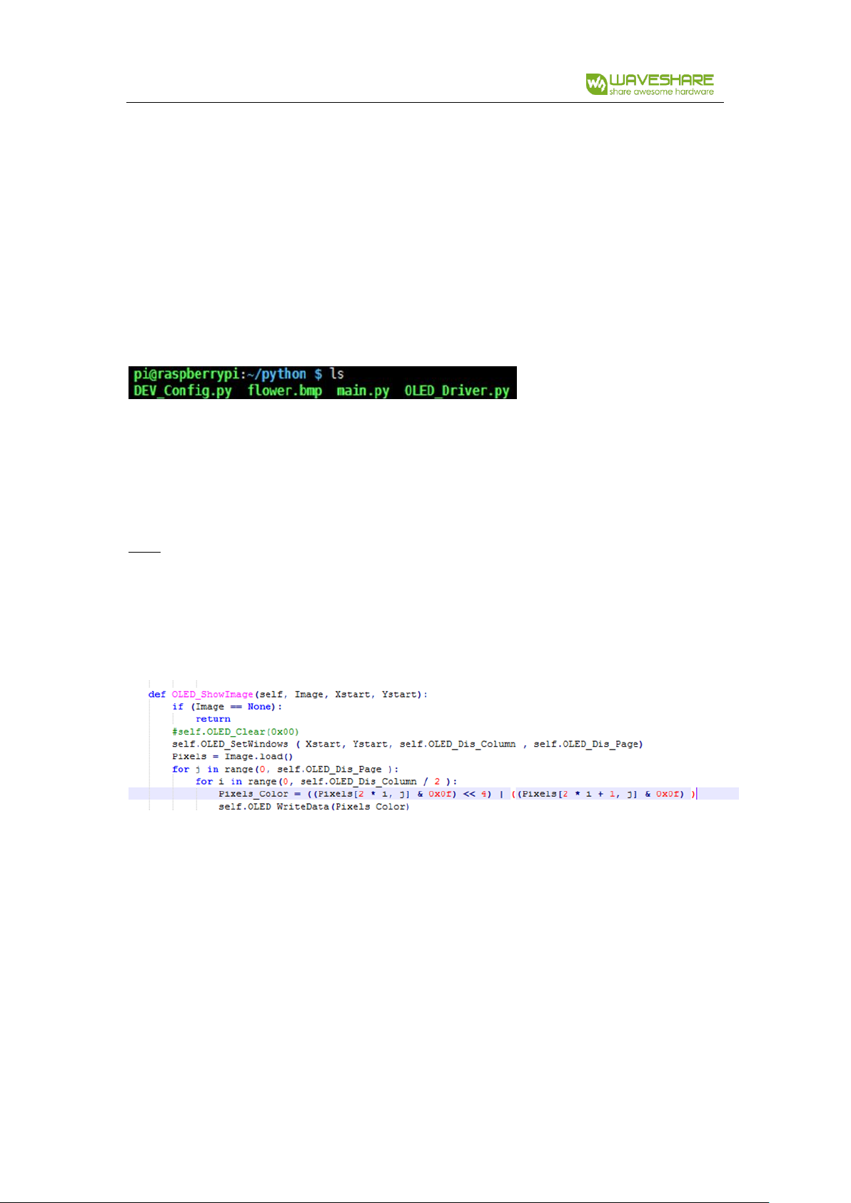
4.3 Python
Execute command ls:
DEV.Config.py: Hardware pin defined here, change USE_SPI_4W and USE_I2C to switch the
communication mode.
OLED.Driver.py: Drive code of OLED
main.py: main function, use Image libraries.
Run codes: sudo python main.py
Note: Some of Raspbian has no image libraries, in this case, you can run this command to install
it: sudo apt-get install python-imaging
Image is an image handle library of python, it uses an image object to express an image.
Use new to create a blank image, set the size as resolution of OLED, and calling Draw libraries to
paint it, finally transmit the image data to OLED to display.
Image.new("L", (OLED.OLED_Dis_Column, OLED.OLED_Dis_Page), 0); “L” is grayscale.
For python, you can use open function to open an image instead of converting to arrays.
Please set the image to 16-bit grayscale and make sure the size of image doesn’t larger than the
resolution.
4.4 Auto-run after booting.
Initialize auto run in Raspberry Pi by configuring code of /etc/rc.local file:
sudo vim /etc/rc.local
Before exit0 add:
sudo python /home/pi/python/demo.py &
Important: to place the program /home/pi/python/demo.py at the same director, you can input
command pwd to get the path. And & character is necessary at the end of command line,

1.5inch OLED Module User Manual
otherwise probable need to reinstall the system (impossible terminate the process by pressing
ctrl+c, impossible to login with pi user permission).
CO NVER T I MA GE T O AR R A YS
1. Convert Image data
Open 16-bit grayscale by Image2Lcd software, and set:
输出数据类型(Output data type): C 语言数组(*.c)
扫描方式 (Scanning type): 水平扫描(horizontal scanning)
输出灰度(Output grey level): 16 灰 (16-bit grey level)
最大宽度和高度(The max width and height):128 128 (The resolution of OLED)
Then check the option 包含图像头数据(Contain Header). The header is required while
analyze image data.
2. Analyzing header of image
For 16-bit grayscale image, the header likes that:
typedef struct _HEADGRAY
{
unsigned char scan;
unsigned char gray;
unsigned short w;
1.5inch OLED Module User Manual
unsigned short h;
}HEADGRAY;
It is totally 6 bytes:
The first byte defines the scanning way:
Bit7: 0: from left to right; 1: from right to left
Bit6: 0: from top to bottom; 1: from bottom to top
Bit5: 0: the pixels in the byte are ordered by DESC; 1: the pixels in the byte are ordered by
ASC
Bit4: 0: The byte order of WORD type is same as PC; 1: The byte order of WORD type is
contrary to PC
Bit3-2: Reserved
Bit1-0: [00]: Horizontal Scanning; [01]: Vertical Scanning; [10]: Data horizontal and Bytes
Vertical; [11]: Data vertical and Bytes horizontal
The second byte is the value of gray level:
1: monochrome
2: 4-bits grayscale
4: 16-bits grayscale
8: 256 color
12: 4096 color
16: 16-bits multicolor
24: 24-bits multicolor
32: 32-bits multicolor
And the rest is the width and height of the image.
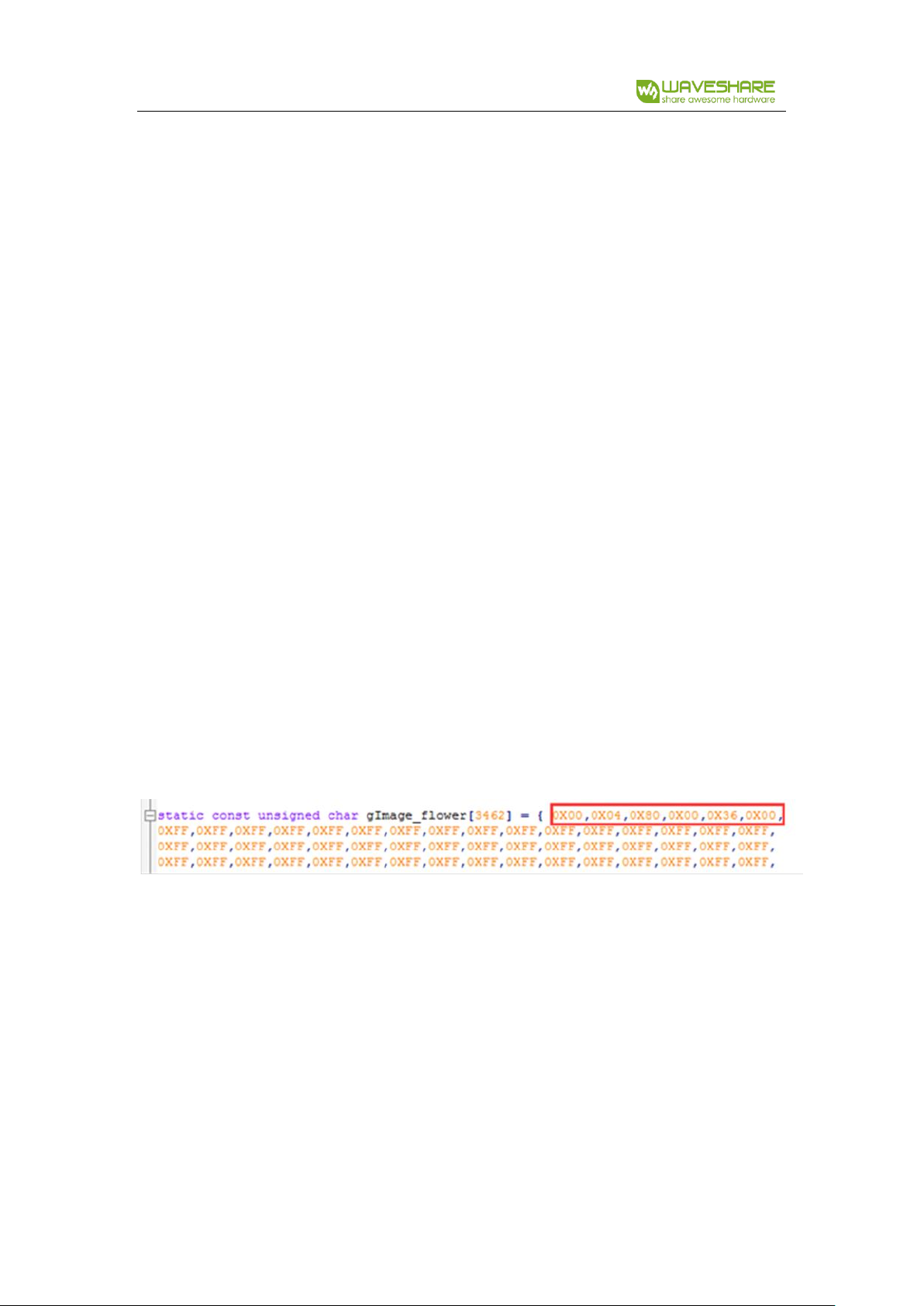
For example:
The header we used on the sample code is that:
We could get the information: Scanning from left to right, 16-bits grayscale. The width and
height of image are 128 and 54 separatelly.
 Loading...