


USER GUIDE
Low-Noise QCL Driver — Laboratory Series
1
TABLE OF CONTENTS PAGE
GENERAL OVERVIEW 2
SAFETY 3
QUICK CONNECT GUIDE 4
PIN DESCRIPTIONS 6
EXTERNAL MODULATION TRANSFER FUNCTIONS 6
ELECTRICAL SPECIFICATIONS 7
THEORY OF OPERATION 9
OPERATING INSTRUCTIONS (STAND-ALONE) 9
OPERATING INSTRUCTIONS (REMOTE) 17
TROUBLESHOOTING 22
ADDITIONAL TECHNICAL NOTES 25
MECHANICAL SPECIFICATIONS 27
CE DECLARATION OF CONFORMITY 28
WARRANTY & CERTIFICATION 29
ORDERING INFORMATION
PART NO DESCRIPTION
QCL500 LAB 500 mA Low Noise QCL Instrument
QCL1000 LAB 1.0 A Low Noise QCL Instrument
QCL1500 LAB 1.5 A Low Noise QCL Instrument
QCL2000 LAB 2.0 A Low Noise QCL Instrument
NOISESCAN Noise Characterization Scan
55-110014 SMA-BNC Cable
55-110015 USB Cable
WCB310 Shielded SMA-SMA Cable
QCL TL LOW
QCL TL 1500 Resistive Test Load for QCL1500
QCL TL 2000 Resistive Test Load for QCL2000
RCKMT-LAB SNGL 19” Single Unit Rack Mount Kit
RCKMT-LAB DUAL 19” Double Unit Rack Mount Kit
INTLK REPL KIT
(included with purchase)
Resistive Test Load for QCL500 or
QCL1000
Interlock Replacement Kit with
BNC terminator and modifi ed
D-SUB connector to override
interlocks
Pb
RoHS
1
Covered by U.S. Patents 6,696,887; 6,867,644 and 7,176,755. Licensed from Battelle Memorial Institute
e
Compliant
Applies to Product Revision A
© April 2015

GENERAL OVERVIEW
• Output currents of 500 mA, 1 A, 1.5 A, 2 A
• Low noise: <0.4 A RMS up to 100 kHz
(QCL500, typical)
• Compliance voltage is adjustable, 10 to 20 V
(NOTE: The unit will only deliver the voltage
that the load requires, up to the compliance
voltage limit.)
• Analog modulation up to 2-3 MHz
• Constant Current Mode operation
• Touchscreen with intuitive user interface
• CE compliant, compatible with CDRH laser
regulations
• Feature-rich for research projects
» USB and Ethernet interfaces with software
included
» Auto voltage/current scan function
» Data collection using a computer or USB
fl ash drive
» Field upgradeable fi rmware
» Sophisticated error handling
THE LOWEST-NOISE DRIVER
AVAILABLE
These low noise QCL instruments have the lowest current
noise density of any commercially available. Powering your
QCL with this patented1 driver gives you narrow linewidth,
stable center wavelength, and repeatable scans.
INTUITIVE USER INTERFACE AND
SUPERIOR SOFTWARE CONTROL
With Wavelength’s plug and play instrument, you have the
ability to quickly set the controls using either the instrument or
a remote computer.
PROTECT YOUR QCL INVESTMENT
All the essential control and monitor functions you expect in a
Wavelength laser driver are incorporated into this instrument,
along with protection circuitry to safeguard your QCL from
minor power source faults, over-temperature conditions, and
electrical faults.
The soft-clamping current limit can be set without enabling the
driver output, and uses a brick-wall never-exceed limit circuit
to protect the QCL from potentially damaging overcurrent
situations.
» Save and recall functions for specifi c set
ups
• Rack mountable: 2 U height and ½ rack width
• Safety features protect your QCL investment
F E A T U R E S
» Adjustable soft-clamp current limit, with
Brick-Wall Never-Exceed circuitry
» Password protection available to lock out a
selectable control set
» Key switch, active, and passive interlocks
» Brown-out & overvoltage protection
» Power supply overcurrent protection
» Driver over-temperature protection circuit
» Relay shorts output when current is
disabled
» AC input and patented power supply
fi ltering
» 2 second turn-on delay — adjustable
» 1.5 msec current ramp
OEM VERSION AVAILABLE
Once you have fi nalized your work, the QCL circuitry is
available in compact OEM versions.
APPLICATIONS
Due to their unique construction, QCLs operate with high
power in the near-IR through terahertz ranges. These
wavelengths are particularly suited to detection of molecules
signifi cant to humans.
Applications for the lower noise QCL driver include: remote
detection of explosive materials, medical diagnosis using the
breath, non-invasive glucose testing, emissions monitoring of
the atmosphere or marine environments, and pharmaceutical
process quality control. Additional applications include
anesthesia and hospital air quality monitoring, leak detection,
and remote imaging.
1
Covered by U.S. Patents 6,696,887; 6,867,644 and
7,176,755. Licensed from Battelle Memorial Institute
2

SAFETY
DEFINITIONS
CHASSIS GROUND Symbol
CAUTION: A condition that has the potential to
cause damage to property or instrument.
WARNING: A condition that has the potential to
cause bodily harm or death.
GENERAL
• Observe all Cautions and Warnings both in the User
Guide and on the instrument.
• Use the QCL instrument as specifi ed in this guide or the
protection provided by this instrument may be impaired
and the warranty will be voided.
• Use good laser safety practices when using the QCL
instrument.
• Before proceeding, it is critical that you take precautions
to prevent electrostatic discharge (ESD) damage to your
laser.
• Locking the instrument with the key switch disables the
output current. The key can only be removed when in the
LOCK position.
FUSES
• Disconnect the power to the QCL instrument before
changing the fuses.
• T o prevent damage to the QCL instrument when replacing
fuses, locate and correct the problem that caused the fuse
to blow before re-applying power.
• To avoid fi re hazard, use only the specifi ed fuse with the
correct type number, voltage, and current ratings, and use
only the recommended replacement parts.
CAUTIONS
The QCL instrument has no user-serviceable parts.
Other than the fuses, the QCL instrument is not
designed to be maintained by the user nor does it
contain any parts that can be repaired by the user.
All maintenance and repairs must be performed by
Wavelength or the warranty will be void.
Use a soft cloth to remove dust from the QCL
instrument. Do not expose the QCL instrument to
any liquids, sprays, or solvents. To avoid electrical
shock, unplug the power cord before cleaning the
instrument.
Before connecting to the power source, make sure
the correct cables and voltage for your area are
set. The voltage selection is available on the back
of the instrument. See the Quick Start Guide for
instructions on changing the voltage.
POWER CORDS
• This equipment is grounded through the AC power cord
grounding conductor.
• Use only the earth-grounded power cords that are
recommended in this user guide.
• Route power cords and other cables so that they cannot
be damaged.
• Position the QCL instrument in a location that makes it
easy to quickly disconnect the power cord.
• To avoid fi re hazard, use only the specifi ed power cords
with the correct grounding, voltage, and current ratings.
WARNINGS
Position the QCL instrument so that access to the
Main Power On/Off switch on the back panel is
easily accessed.
Do not use the QCL instrument if there is evidence
of damage from shipping; damaged equipment
can present signifi cant safety hazards. If you
suspect the QCL instrument is damaged, contact
Wavelength technical support before attempting to
operate the instrument.
To avoid electrical shock, use the recommended
earth-grounded power cables and properly earthgrounded, 3-prong receptacles only. Failure to
follow this precaution can result in severe injury.
To avoid injury, do not tell the engineers how to
do their jobs. Let them muddle through until they
decide to read the User Guide.
3

QUICK CONNECT GUIDE
INSTALL FUSE & SELECT VOLTAGE
Figure 1. Fuse Box and Voltage Selector
1. On the back panel, locate the Fuse Box and Voltage
Selector receptacle. (See the Rear Panel diagram on
page 10 for the location.)
2. Insert a small fl athead screwdriver into the slot (1) at the
top of the receptacle and twist to open faceplate. The red
fuse drawer and fuses are located in the Ship Kit.
3. On the face of the fuse drawer are two voltage choices.
Based on your country, select the proper fuses to install.
VOLTAGE FUSE PART NUMBER
100-120 V
220-240 V
1.25 A, 250 V,
fast blow
0.63 A, 250 V,
fast blow
Littelfuse 5 x 20 mm,
Part #02351.25HXP
Littelfuse 5 x 20 mm,
Part #0217.630MXP
WIRE A TEST LOAD
Use of a test load is recommended for setup of the QCL
instrument. Use the Wavelength test loads listed on page 1, or
when building your own test load, a 10 resistor with a 50 W
power rating is recommended for the QCL500, QCL1000,
and QCL1500. For the QCL2000, a 50 W 5 resistor is
recommended.
• Install the test load by either connecting to the QCL SMA
port or wiring the load to PIN 5 and PIN 9 on the QCL
D-SUB as shown in Figure 3.
12345
6789
1
QCL
SMA
1
NOTE: The SMA case is electrically connected to the QCL chassis.
Figure 3. QCL Wiring Diagram
Pin 9 QCL +
or SMA Outer Ring
QCL D-SUB
QCL
CAUTION: It is imperative that the correct voltage
is used. Serious damage can occur if the incorrect
voltage is selected.
4. Insert the fuses as shown in Figure 2, with a short fuse
at the contact end of the receptacle. Then, turn the drawer
until the correct voltage label is at the top and replace it
in the receptacle. Press fi rmly to make sure the drawer is
completely seated. It should be fl ush with the receptacle.
Figure 2. Fuse Installation and Voltage Selector
5. Close the faceplate, again pressing fi rmly until it is fl ush.
The correct voltage label is shown through the Voltage
Window (2) on the faceplate.
QCL
Pin 5 QCL -
or SMA Center Pin
QCL Driver
Current Sink
-V
Figure 4. QCL Polarity Diagram
4

SETUP INTERLOCKS
ENABLE CURRENT
The Wavelength Interlock Replacement Kit includes a male
D-SUB with the passive interlock pins shorted and a BNC
terminator.
1. For the passive interlock, on the back panel, short PIN 1
and PIN 2 on the QCL D-SUB.
2. For the active interlock, on the back panel, insert a BNC
terminator in the ACTIVE LOCK BNC port.
3. On the front panel, the key switch must be on UNLOCK to
enable the current to the QCL.
TURN ON POWER
1. On the back panel, press the power switch to the |. The
front panel power button light pulses slowly.
2. On the front panel, press the Power button. The button
illuminates, the touchscreen activates, and the Control
screen is active.
3. The front panel displays dashes instead of digits until the
unit has fi nished its power-up sequence (~10 seconds).
Press the ENABLE button. There is a standard 2-second
delay before the button illuminates and the current fl ows.
SHUTDOWN THE INSTRUMENT
If the Enable button is illuminated, current is still fl owing to
the test load. Before shutting down, the current needs to be
turned off.
1. Press the Enable button. The button light will turn off and
current to the QCL test load will stop.
2. On the front panel, press the Power button. The
touchscreen will go black but the button light slowly
pulses blue to indicate that the back Power button is still
on. NOTE: Turning off only the front Power button puts
the instrument in Standby mode.
3. On the back panel, press the power switch to O.
SET LIMITS
1. Press to access the Limit Screen.
2. On the Limit screen, press the blue Limit Current value
and rotate the Adjustment knob to change to the desired
value. The instrument will beep when set.
NOTE: The Max Supply V oltage and Cable Resistance values
can be ignored for now.
ADJUST SETPOINT
1. Press to access the Control Screen.
2. Press the Setpoint current value and turn the Adjustment
knob to change it. The instrument will beep when set.
5

QCL D-SUB
)
QCL
d)
PIN DESCRIPTIONS
Pin 9 QCL +
or SMA Outer Ring
Figure 4. Female 9-Pin D-SUB
Table 1. QCL D-SUB Pin-Out
PIN DESCRIPTION
1, 2 Passive interlock pins (must be shorted to enable
current)
3 Chassis ground
4 Not used
5 * QCL- (negative)
6 Not used
7 Not used
8 Not used
9 * QCL+ (positive)
SHELL Chassis ground
* NOTE: Use Pins 5 and 9 for current to the QCL.
MONITOR D-SUB
QCL
Pin 5 QCL -
or SMA Center Pin
QCL Driver
Current Sink
-V
Figure 7. QCL Polarity Diagram
BNC PINS
GROUND
ACTIVE SIGNAL
Figure 8. BNC Pins
EXTERNAL MODULATION BNC
TRANSFER FUNCTIONS
Figure 5. Male 9-Pin D-SUB
Table 2. Monitor D-SUB Pin-Out
PIN DESCRIPTION
1 Alignment LED (+5 V) can source 250 mA
2 Alignment LED ground
3 QCL current enabled indicator (+5 V TTL)
high = disabled
low, ground = enabled
4 QCL current enabled indicator ground
5 Not used
6 Analog setpoint monitor
7 Analog monitor ground
8 Analog output current monitor
9 Analog monitor ground
QCL SMA
+ (groun
The external modulation input, setpoint monitor, and analog current
monitor transfer functions depend on the QCL instrument model and
are all as follows:
QCL500-LAB: 0.1 A / V.
QCL1000-LAB: 0.2 A / V.
QCL1500-LAB: 0.3 A / V.
QCL2000-LAB: 0.4 A / V.
The input range is always 0 – 5 V.
ACTIVE INTERLOCK BNC
Ground the center pin to the outer shell to override the interlock and
allow the current to fl ow to the QCL. If an external circuit won’t be
used, a 50 or 75 terminator is acceptable.
TRIGGER BNC
See Remote Operation on page 21.
QCL- (negative
Figure 6. SMA Pin-Out
6

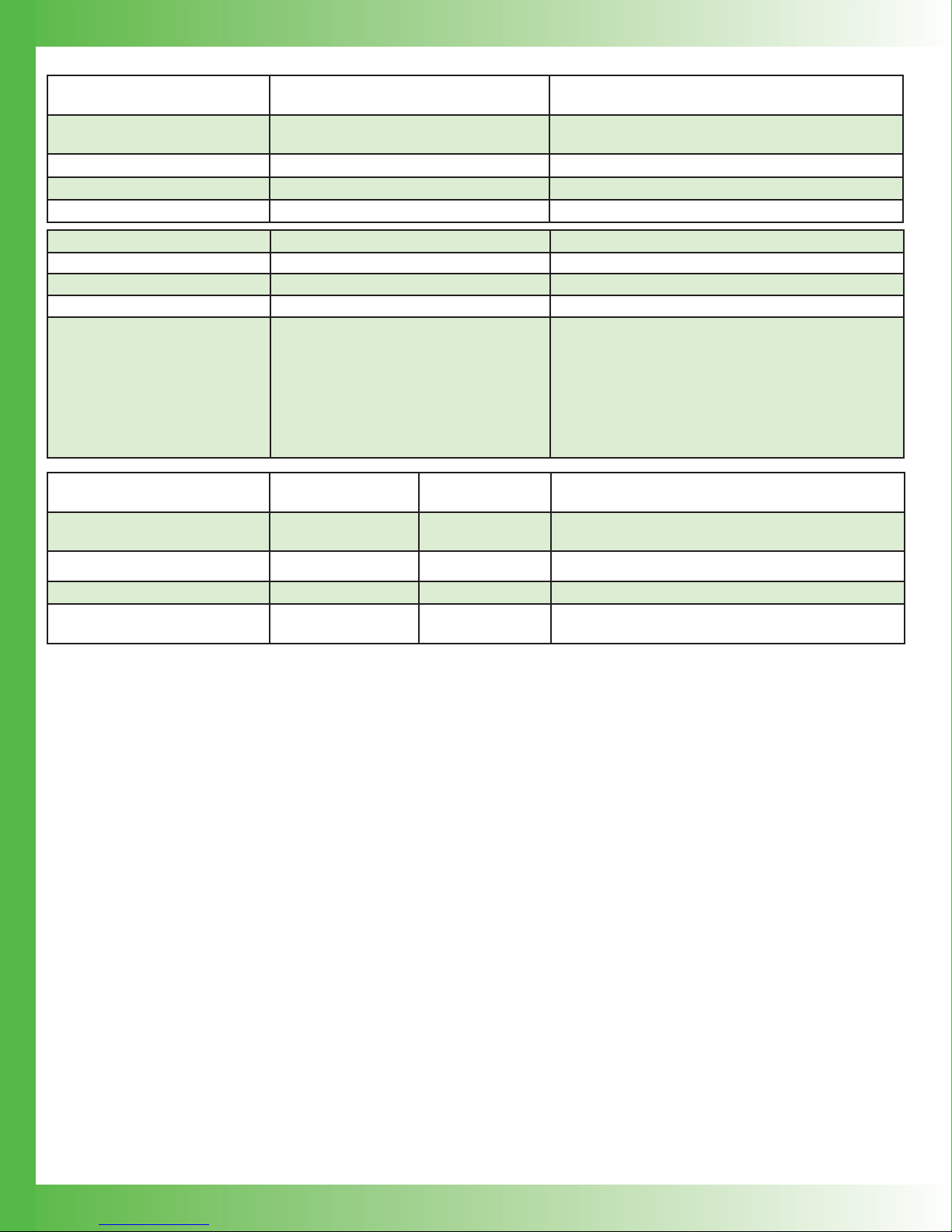
ELECTRICAL SPECIFICATIONS
DRIVER OUTPUT CURRENT MIN TYP MAX UNITS NOTES
Output Current 0.5, 1.0, 1.5, or 2.0 A
RMS Noise Current 0.4 1.0 1.3 A RMS QCL1000 at 500 mA output, 100 kHz test bandwidth
Noise Current Density 1 2 4 nA / Hz QCL1000 at 500 mA, 10 test load
Stability, short and long term 5 10 15 ppm 25°C ambient
Temperature Coeffi cient 5 10 18 ppm / °C
Internal Supply Voltage can be adjusted from the front
panel.
Compliance Voltage Range 10 20 V
Slow Start Current Ramp (after
Enabled)
Delayed Start 2 sec User adjustable
EXTERNAL MODULATION MIN TYP MAX UNITS NOTES
Modulation Bandwidth 2 3 MHz Sinewave
Rise/Fall Time 250 / 200 nsec To full scale
Slew Rate 30 V / sec
Depth of Modulation 90 % At 500 kHz
Input Impedance 1 k
External Modulation Input
Damage Threshold
1.5 msec
-10 to +10 V BNC Connector
NOTE: With this current source, the voltage developed
across the load (laser) is not driven by the controller,
but by Ohm’s Law and the resistance of the load
(laser).
To setpoint
MONITORS AND OUTPUTS VALUE UNIT NOTES
Setpoint Resolution 16 bits 5V = fullscale output
Display Accuracy Measurement
Resolution
Accuracy, Current Output
Monitor vs. Actual Current
(display or analog output)
Accuracy, Current Setpoint vs.
Actual Current
Accuracy , Analog Setpoint
1
Monitor
1
Current Setpoint Monitor is a reference signal only, and may deviate from the actual setpoint by up to 5% when the setpoint is greater
than 10% of full scale.
24 Bits
0.2 % > 5% of full scale
0.5 % < 5% of full scale
0.2 % Internal setpoint
0.2 % External modulation
5 % >10% of full scale
25 % <10% of full scale
CONTINUED ON FOLLOWING PAGE
7
POWER SUPPLY
REQUIREMENTS
AC Power Supply and Line
Frequency
100-120 / 220-240 VAC, 2 A, 50-60 Hz
VALUE NOTES
Switch selectable: 100-120 V and 220-240 V,
appropriate power cord supplied
Fuse for 220-240 V 0.63 A, 250 V, fast blow 5 x 20 mm, Part #0217.630MXP, Littelfuse
Fuse for 100-120 V 1.25 A, 250 V, fast blow 5 x 20 mm, Part #02351.25HXP, Littelfuse
Power Consumption 9.8 Watts at idle, no output to QCL load
GENERAL SPECIFICATIONS VALUE NOTES
Warm-up Time 1 Hour
Remote Interface USB, Ethernet
Warranty One (1) Year
Safety Tested To IEC 61000-3-2
IEC 61000-3-3
IEC 61000-4-2
IEC 61000-4-3
IEC 61000-4-4
IEC 61000-4-5
IEC 61000-4-6
IEC 61000-4-8
IEC 61010-1
European Council Directive 2004/108/EC &
European Council Directive 2006/95/EC
ABSOLUTE MAXIMUM
RATINGS
Case Operating Temperature
Range
VALUE UNIT NOTES
-40 to 50 °C
Humidity 80 % Relative humidity at 30°C (non-condensing)
Weight 12 (~5.4) lbs (kg)
Size
3.47 x 8.86 x 17.72
(89 x 226 x 450)
inches (mm)
8

OPERATING INSTRUCTIONS (STAND-ALONE)
WHAT’S IN THE BOX
• QCL Instrument
• Power Cable, type appropriate for fi nal location
• Red fuse tray
• T wo 0.63 A fuses and two 1.25 A fuses for fuse box on the
back panel
• USB Flash Drive, includes all necessary software,
instrument documentation, and additional storage space
• Keys for the key switch
• Interlock Replacement Kit (interlocks for QCL D-SUB and
Active Interlock BNC)
These instructions are for operating the QCL Laboratory
Series instrument. Fuses are provided but not installed. After
installing the fuses in the fuse box, be sure to install the fuse
box so the correct voltage for your country is showing. We
also recommend using a test load until you are familiar with
operation of the instrument.
REQUIRED AND OPTIONAL
EQUIPMENT
FOR SET UP
THEORY OF OPERATION
The QCL Series low noise drivers are designed expressly to
drive quantum cascade lasers, and utilize patented1 circuitry
to deliver ultra-low noise current and still maintain a wide
modulation bandwidth.
The QCL drivers are controlled current sources; they deliver
the current commanded by the setpoint. The current source
continually monitors the actual output current, compares it to
the setpoint, and adjusts the current if there is a difference
between the two signals.
As current is driven through the load, there is a voltage drop
across the load proportional to the load resistance and current.
As the current increases, the voltage drop may increase to
the point that it reaches the Compliance Voltage limit of the
current source. Once that occurs the current source is no
longer able to increase the current driven to the load even if
you increase the setpoint.
The QCL driver includes features that help protect your laser,
and also make the driver more versatile in a wide array of
applications. These features are explained in detail in the
Operating Instructions.
• The user-adjustable current limit prevents overdriving the
laser even if the external modulation signal is above the
maximum drive current for the laser.
• Over- and under-voltage protection circuits protect the
driver and QCL if the power supply voltages fall outside of
the acceptable operating range.
• Small, narrow headed fl athead screwdriver (required)
• Test load (optional)
• Wavelength Interlock Replacement Kit with interlock
overrides (optional)
COMPUTER REQUIREMENTS FOR
REMOTE OPERATION ONLY (OPTIONAL)
Hardware
• 1 GHz or faster 32-bit (x86) OR 64-bit (x64) processor
• 1 GB RAM 32-bit or 2 GB RAM 64-bit
• 16 GB available hard disk space for 32-bit or 20 GB for
64-bit DirectX 9 graphics device with WDDM 1.0 or higher
driver
Software
• Windows 8, 7 SP1, or Vista SP2 Operating System 4.5
.NET framework
ESD INFORMATION
Before proceeding, it is critical that you take precautions to
prevent electrostatic discharge (ESD) damage to the load.
ESD damage can result from improper handling of sensitive
electronics, and is easily preventable with simple precautions.
• Over-temperature protection circuits safely shut down
the output if the internal temperature of the QCL driver
rises to an unsafe level. The fan turns on to manage the
internal temperature.
• Output slow-start ramps the current to setpoint over
1.5 msec.
• A mechanical relay shorts the output connections when
the output is disabled, and when the QCL driver is
powered off.
1
Covered by U.S. Patents 6,696,887; 6,867,644 and
7,176,755. Licensed from Battelle Memorial Institute.
9

REAR PANEL
1
2
CAUTION:
No user serviceable parts. Do
not remove cover.
Covered by U.S. Patents:
6,696,887
6,867,644
7,176,755
3
4
!
SERIAL #
WARNING: Before powering on
device, verify voltage setting is
correct and proper fuses are
installed.
CHASSIS
GND
QCL
5
Figure 9. Rear Panel
QCL
MONITORS
8
6
9
MOD
7
10
ACTIVE
LOCK
11
FUSE ~250V, 1.25AF (5 x 20mm)
100-120 VAC, 1.25 A, 50-60 Hz
ETHERNETUSB
12
TRIGGEREXT
FUSE ~250V, 0.63AF (5 x 20mm)
220-240 VAC, 0.63 A, 50-60 Hz
13
Table 3. Rear Panel Functions
NAME DESCRIPTION
1 Fan Vent Do not block air fl ow.
2 Chassis Ground Physical connection to chassis and electrical earth ground.
3 QCL SMA SMA connector, alternate connection to QCL.
4 QCL D-SUB 9-Pin female D-SUB connector.
5 Monitors 9-Pin male D-SUB connector.
6 USB USB port, connection between instrument and a computer.
7 Ethernet Ethernet port, connection between instrument and a computer or network.
8 EXT MOD External Modulation: BNC connector, setpoint signal generator input.
9 Active Lock BNC connector, active interlock, tie center pin to GND to enable output.
10 Trigger
11
12 Power Switch AC power switch that powers the instrument.
13 Power Plug IEC AC line input.
Fuse Box and Voltage
Selector
BNC connector output, allows instrument to trigger external device for synchronizing
measurement.
Removable fuse drawer allows user to switch between 115 V and 230 V. Fuses need to be
installed prior to operation.
10

INSTALL FUSES AND SELECT
PROPER VOLTAGE
Figure 10. Fuse Box and Voltage Selector
1. On the back panel, locate the Fuse Box and Voltage
Selector receptacle. (See the Rear Panel diagram on
page 10 for the location.)
2. Insert a small fl athead screwdriver into the slot (1) at the
top of the receptacle and twist to open faceplate. The red
fuse drawer and fuses are located in the Ship Kit.
3. On the face of the fuse drawer are two voltage choices.
Based on your country, select the proper fuses to install.
CONNECT POWER
Insert the female end of the IEC AC power cord into the Power
receptacle on the back panel and then plug the male end into
the power source.
WIRE A TEST LOAD
Use of a test load is recommended for setup of the QCL
instrument. Use the Wavelength test loads listed on page 1, or
when building your own test load, a 10 resistor with a 50 W
power rating is recommended for the QCL500, QCL1000,
and QCL1500. For the QCL2000, a 50 W 5 resistor is
recommended.
• Install the test load by either connecting to the QCL SMA
port or wiring the load to PIN 5 and PIN 9 on the QCL
D-SUB as shown in Figure 12.
12345
6789
QCL D-SUB
VOLTAGE FUSE PART NUMBER
100-120 V
220-240 V
1.25 A, 250 V,
fast blow
0.63 A, 250 V,
fast blow
Littelfuse 5 x 20 mm,
Part #02351.25HXP
Littelfuse 5 x 20 mm,
Part #0217.630MXP
CAUTION: It is imperative that the correct voltage
is used. Serious damage can occur if the incorrect
voltage is selected.
4. Insert the fuses as shown in Figure 11, with a short fuse
at the contact end of the receptacle. Then, turn the drawer
until the correct voltage label is at the top and replace it
in the receptacle. Press fi rmly to make sure the drawer is
completely seated. It should be fl ush with the receptacle.
1
QCL
SMA
1
NOTE: The SMA case is electrically connected to the QCL chassis.
QCL
Figure 12. QCL Wiring Diagram
Pin 9 QCL +
or SMA Outer Ring
Test Load
Pin 5 QCL -
or SMA Center Pin
QCL Driver
Current Sink
-V
Figure 13. Test Load Polarity Diagram
Figure 11. Fuse Installation and Voltage Selector
5. Close the faceplate, again pressing fi rmly until it is fl ush.
The correct voltage label is shown through the Voltage
Window (2) on the faceplate.
11

SET UP INTERLOCKS
TEXT AND ICON COLOR KEY
The Wavelength Interlock Replacement Kit includes a male
D-SUB with the passive interlock pins shorted and a BNC
terminator.
1. For the passive interlock, on the back panel, short PIN 1
and PIN 2 on the QCL D-SUB.
2. For the active interlock, on the back panel, insert a BNC
terminator in the ACTIVE LOCK BNC port.
3. On the front panel, the key switch must be on UNLOCK to
enable the current to the QCL.
NOTE: To disable operation, turn the key switch to the
LOCKED position. The key can only be removed when in the
locked position.
FRONT PANEL
TEXT
Text indicates current state.
White, Green Uneditable fi eld, for information only.
Blue Editable fi eld, touch to select or toggle fi eld
(text highlights and changes color), adjust
using either the touchscreen or adjustment
knob. Instrument beeps and text returns to
blue when values are set. Touch again to
cancel selection.
ICONS
Icon color indicates current state.
Blue Screen is active.
Grey Screen is inactive, touch icon to access that screen.
3
QCL1000
LAB
4
ENABLE
POWER
DATA
1
2
5
Figure 14. Front Panel
Table 4.
Table 5. Front Panel Functions
NAME DESCRIPTION
1 Power Button
2 Adjustment Knob Turn to adjust the numeric values. Instrument beeps when values are set.
3 Enable Button Allows instrument to deliver current to the QCL. Glows blue when current is enabled.
4 Keylock Switch
5 Data Port
Powers the application electronics. Glows blue when application electronics power is on and unit
is operational, slow pulses blue when on Standby and only the back panel power switch is on.
UNLOCK allows laser output current to fl ow, LOCK disables laser output current. NOTE: The
key can be removed only in LOCK position.
USB fl ash drive, used to update the fi rmware or save data. This is not used for remote USB
control of the instrument.
12

TURN ON QCL INSTRUMENT
1. Press the Power switch on the back panel to |. The front
panel power button light slowly pulses.
2. Press the Power button on the front panel, the button
illuminates, touchscreen is activated, and the Control
screen is active.
NOTE: Turning off front Power button powers down the
application electronics and puts the unit into standby
mode. Turning off rear Power switch powers down all
electronics and settings return to factory default.
3. The front panel displays dashes instead of digits until the
unit has fi nished its power-up sequence (~10 seconds).
SET LIMITS
1. Press to access the Limit Screen.
ADJUST THE SETPOINT
1. Press to access the Control Screen.
2. Press the Setpoint value and turn the Adjustment knob
until the desired operating current is displayed.
2. Press Limit Current, Maximum Supply Voltage, and/or
Cable Resistance values and rotate the Adjustment knob
to change each value. The instrument will beep when set.
Figure 15. Limit Screen
NOTES:
• The Limit Current should not exceed the damage current
threshold of your QCL.
• The Maximum Internal Supply Voltage can be lowered
to minimize internal instrument temperature or to act as a
compliance voltage clamp on the QCL output current. See
Additional Technical Notes on page 25 for optimization
instructions.
• The Cable Resistance range is 0 – 1 .
QCL Voltage displays the voltage at the QCL DSUB or
SMA terminals. To account for voltage loss across the
cable to the QCL, you can enter a non-zero value for
Cable Resistance.
The QCL Voltage will now display as:
Voltage Displayed = Voltage@Pins - (Cable Resistance x Operating Current)
• The minimum limit current is about 8% of full scale.
Figure 16. Control Screen
NOTE: The Control screen is on by default when the
instrument is turned on. The Mode is Constant Current by
default and cannot be changed.
DISPLAY EXISTING CURRENT AND
VOLTAGE VALUES
Press to access the Monitor Screen.
Values on this screen cannot be changed and are for
information only.
Figure 17. Monitor Screen
13

ENABLE THE QCL INSTRUMENT
Press the Enable button on the front panel. The button will
glow blue only when current is delivered to the load. There is
a standard 2-second delay before the button illuminates and
current fl ows.
VI SCAN
1. On the Control screen, press to access the VI
scan screen.
2. Press the Current Start value to select the current at
which to start the scan. Turn the Adjustment knob to
change it.
NOTES:
• The step interval time is approximate. In the scan fi les,
time intervals are slightly more than the step interval
indicated on the instrument. Each interval builds on the
previous one.
• Should the Step Size interval not fi nish at the Stop Current,
the reading is still taken and recorded. For example, if
the Start Current is 250 mA and the Stop Current is 1.04
A with a Current Step of 250 mA, a reading is taken at
1000 mA (1 A) and 1040 mA (1. 04A) but not at 1250 mA
(1.25 A).
• After a VI scan is completed, the output is disabled and
the setpoint is zeroed.
SAVE OR RECALL SETTINGS
Press to access the Save/Recall Screen.
Figure 18. Scan Screen
3. Press the Current Stop value to select the current at
which to stop the scan.
4. Press the Step Size value to select the current interval at
which to take a measurement. The maximum interval is
10% of full scale. Minimum step is 1% of full scale.
5. Press the Time Interval value to select the amount of time
to allow the current to settle. For the best data accuracy,
use a Time Interval of 2 seconds or more. The minimum
time interval is 0.1 seconds.
6. Insert the USB fl ash drive in the USB slot on the front
panel.
7. Press the green Run button to start the scan. When
fi nished, data is saved to the USB fl ash drive with
the fi lename viscanxx.txt, where xx starts at 00 and
increments.
8. To stop mid-scan, press the red Stop button to abort the
scan. Any data collected during the aborted scan is saved
to the USB fl ash drive.
Under Save Settings to, press the blue text
to toggle through the Profi le options, select
one, and then press the Save icon.
The following variables are saved:
OPERATION SETTINGS VI SCAN SETTINGS
Setpoint VI Start Current
Current Limit VI Stop Current
Max Supply Voltage VI Step Size
Cable Resistance VI Time Interval
Display Brightness
Beeper Status
Figure 19. Save / Recall Screen
14

Under Recall Settings from, press the
blue text to toggle through the saved Profi le
options, and then press the Recall icon to
recall the saved settings. Select Factory to
restore the settings to the factory defaults.
SETTINGS SCREEN
Press to access the Settings Screen
Move the slider bar on the touchscreen to change the display
brightness. Press the blue text to toggle the Beeper on-off
setting.
EXTERNAL MODULATION
(EXT MOD) BNC
This is the external modulation input. The voltage input on
this BNC sums with the DC value on the screen. The input
impedance is 1 k . To calculate the external modulation
signal voltage, see the next section for the transfer function,
and use the following equation:
EXT_MOD
= I
CAUTION: Connect the oscilloscope across the
test load only — never connect the oscilloscope
across a quantum cascade laser.
V
If the external modulation input causes the driver to reach the
current limit, the output signal will be clamped at the limit level
but will not switch off.
The bandwidth of the Current Monitor is lower than the
bandwidth of the output. To monitor the actual output
waveform at high frequencies, connect an oscilloscope across
the output pin on the MONITOR D-SUB, Pin 8 (positive), and
Pin 9 (ground) while using the resistor test load.
/ Transfer Function
SETPOINT
Figure 20. Settings Screen
LOCK OR UNLOCK SETTINGS
(OPTIONAL)
Settings are not locked.
This is the default. Critical values set with the
Adjustment knob can be locked. Press to lock
the settings.
Settings are locked.
Press to unlock the settings.
Settings are locked and password protected.
Locked settings that are password protected
can only be locked and unlocked using a remote
computer.
EXTERNAL MODULATION BNC
TRANSFER FUNCTIONS
The external modulation transfer function depends on the
QCL instrument model and is as follows:
QCL500-LAB: 0.1 A / V.
QCL1000-LAB: 0.2 A / V.
QCL1500-LAB: 0.3 A / V.
QCL2000-LAB: 0.4 A / V.
The input range is always 0 – 5 V.
15

ADDITIONAL CAPABILITIES
ANALOG CURRENT MONITOR
This signal is the sum of the DC setpoint as shown on the
screen and the external modulation input.
To monitor the analog current level:
1. Connect the Analog output Current Monitor (PIN 8) on the
MONITOR D-SUB to an oscilloscope.
2. Connect an Analog Monitor Ground (PIN 7 or PIN 9) to
oscilloscope ground.
SETPOINT CURRENT MONITOR
This is a reference only and can be off by as much as 5%
when setpoint is >10% of full scale.
To monitor the setpoint current:
1. Measure the voltage on the Analog Setpoint Monitor (PIN 6).
2. Ground for that measurement is the Analog Monitor Ground
(PIN 7 or PIN 9).
The setpoint monitor and analog current monitor transfer
functions depend on the QCL instrument model and are all
as follows:
QCL500-LAB: 0.1 A / V.
QCL1000-LAB: 0.2 A / V.
QCL1500-LAB: 0.3 A / V.
QCL2000-LAB: 0.4 A / V.
The input range is always 0 – 5 V.
ALIGNMENT LED DRIVE
+5 V, up to 250 mA sourced.
To drive an alignment LED, on the MONITOR D-SUB
1. Connect an LED to the Alignment LED +5V (PIN 1).
2. Ground the LED at the Alignment LED Ground (PIN 2).
ENABLE STATUS INDICATOR
This is a +5 V TTL indicator. If current to the QCL output
is enabled, the voltage between PIN 3 and PIN 4 on the
MONITORS D-SUB will be low. It will be high if current is
disabled.
16

OPERATING INSTRUCTIONS (REMOTE)
http://www.teamwavelength.com/support/software.php.
http://www.teamwavelength.com/support/software.php
INSTALL THE LAB QUICKCONNECT
APPLICATION SOFTWARE
The QuickConnect software is necessary for remote operation
of the instrument. The software can be installed on the remote
computer from either the USB fl ash drive included with your
instrument or from the Wavelength website.
• On the USB fl ash drive, the software is located in the
\ setup folder.
• On the Wavelength website, the link to the software is
located at
http://www.teamwavelength.com/support/software.php.
NOTE: .NET 4.5 software is required to run the application. If
it is not currently installed on the remote computer, it will be
installed automatically when you insert the fl ash drive.
TO INSTALL THE SOFTWARE,
1. From the USB fl ash drive or the Wavelength website
and in the fi le dialog box, select the software version that
corresponds to your computer system type, either 32-bit
or 64-bit. NOTE: If the incorrect system type is selected,
an error message will appear and the software will not
install.
2. Click the computer system’s setupxx.exe fi le, where “xx”
refers to the system type. The Preparing to Install dialog
box opens and the software automatically extracts the fi le.
3. On the Welcome window, click Next.
4. On the Destination Folder window, click Next to accept
the default Wavelength folder or Change to select a
different folder. When the new folder has been selected,
click Next.
5. On the Ready to Install window , review the settings, click
Install.
6. On the Windows Security window, click Install.
7. On the Completed window, select the Launch the
program checkbox to open the application and then click
Finish.
The fi le is found at:
http://www.teamwavelength.com/support/software.php
3. Extract the fi le on the fl ash drive. It should contain the
following fi les:
\INSTALL.INI
\QCLxx\ABL.IMG
\QCLxx\APP.IMG
\QCLxx\INSTALL.INI
NOTE: “QCLxx” is replaced with the instrument model number,
such as QCL2000.
4. Insert the fl ash drive into the front DATA port on the
instrument. The update automatically begins installation.
5. At the Apply the fi rmware screen, click Yes. The fi rmware
update installs.
6. Once the update is complete, click OK and reboot the
instrument by turning off the front and rear panel power
buttons and turning them back on again.
7. (Optional) To confi rm the latest version is installed on
the instrument, after the instrument is on, swipe the
touchscreen to show the system information screen. The
new version number is displayed.
CONNECT AN INSTRUMENT TO A
REMOTE COMPUTER
1. Connect the QCL instrument to a power source. See
the Stand Alone operation instructions on page 11 for
more information.
2. Connect the instrument to the computer using a USB or
Ethernet cable. If connecting more than one instrument, a
USB or Ethernet hub may be required.
3. Turn on the rear panel Power switch. The front panel
Power button pulses blue.
4. Turn on the front panel Power button. The button glows
steadily blue and the touchscreen activates.
UPDATE THE INSTRUMENT
FIRMWARE
Updates to the instrument fi rmware are available on the
Wavelength website.
1. Turn the instrument completely off at both the front and
rear panels, and then turn it completely on again.
2. On the Wavelength website, download the ZIP fi le that is
specifi c to your QCL Laboratory Series model and save
the update fi le to a fl ash drive.
ACCESS THE INSTRUMENT ON A
REMOTE COMPUTER
1. On the computer and from the Start Menu, click All
Programs, then click Wavelength Electronics, and then
LAB QuickConnect. The LAB QuickConnect Application
window opens.
2. In the LAB QuickConnect Application window, click
Open Instrument.
3. In the Choose Instrument To Open window, select the
instrument to connect to and click Open.
17

Figure 20. Include USB Devices window
NOTES:
• The Include USB Devices checkbox is selected by
default and any powered instruments currently connected
to the computer via a USB cable appear in the list.
• If you are unsure which instrument to select, on the
instrument, swipe the touchscreen fi rmly from left to
right. The instrument details screen, including the serial
number, appears.
• Instruments that are connected to subnets can be added
to the list.
1. Select the Include Network Devices checkbox, add
the IP address or host name of the subnet, and then
click Add Host.
2. Click Refresh. Any instruments connected to that
subnet appear in the list.
Figure 22. Remote Computer Control screen
Figure 23. Instrument touchscreen when controlled remotely
CHANGE THE TURN-ON DELA Y
The default delay between the time the current to the laser
is enabled and the current actually fl ows is 2 seconds. This
turn-on delay can be set to a minimum of 0 seconds and a
maximum of 5 seconds.
1. On the Operation Tab, click on the blue text below Turn-
On Delay.
2. Change the value and tab to a new editable fi eld to save
the change.
Figure 21. Include Network Devices window
3. On the Instrument Operation tab, in the lower left, click
Seize. Control of the instrument will transfer from the
instrument to the computer and a screen of all editable
fi elds appears. The computer screen is editable and the
instrument screen is not.
NOTE: One instrument can be controlled remotely at a time.
CONTEXTUAL HELP
At any time, contextual Help Information appears on the right
side of the window when the pointer is placed over a button
or screen element. Technical Support information, such as the
instrument serial number and Wavelength contact information
is available when the pointer is placed over the grey frame
surrounding the window.
18

SUPER USER VS. NORMAL USER
PERMISSIONS
There are two levels of permissions when modifying the
instrument controls, Super User and Normal User.
Super User: The Super User has the ability to modify any
remote operation and to assign permissions for Normal
Users. A password is required to access Super User features.
Upon fi rst sign in, the password entered is the new Super
User password and is required for subsequent sign ins.
Normal User: The Normal User is primarily used for Local
operation. The Super User can restrict access to specifi c
inputs on the instrument.
ACCESS SUPER USER MODE
When control of the instrument is fi rst seized, it is in Normal
User mode.
1. On the Instrument Operation tab and at the bottom, click
Super User.
2. Type the password in the text box and click OK. Select
the Show Password checkbox to type the password as
text.
NOTE: Upon fi rst sign in, the password typed becomes the
password for subsequent sign ins.
EDIT INSTRUMENT PROFILES
Profi les can be edited in Super User mode or when Normal
Users are not restricted from saving profi les.
1. In the Profi le Editor Window and in the Available
Profi les menu, select a profi le. The factory default profi le,
Profi le 0: Factory Default, cannot be changed.
2. Type values in the Profi le Data boxes.
3. (Optional) In the Description Line 1 and 2, type a
description of the profi le. This text replaces the Save-
Recall Profi le text on the instrument. A maximum of 14
characters are saved.
4. (Optional) To grant Normal Users read-write permissions,
select the appropriate checkbox.
• Local User Can Save/Modify This Profi le: Allows
any user to change any preset profi le value on the
instrument.
• Normal User Can Recall: Allows any user to recall
preset profi les. This is selected by default.
5. Click Apply to Instrument and/or Save.
• Click Apply to Instrument to change the values
on the instrument but not save the changes to the
Profi le.
• Click Save to save changes to the Profi le but not
change the values on the instrument.
• Click Apply to Instrument and then Save, to apply
changes to the instrument and then save the changes
to the Profi le.
Figure 24. Enter Password window
6. .
Figure 25. QCL-LAB Profi le Editor window
19

EDIT ADV ANCED OPTIONS
CHANGE SUPER USER PASSWORD
Advanced Options can only be edited in Super User mode.
Figure 26. Advanced Options window
CHANGE PERMISSIONS
Permissions can only be modifi ed in Super User mode and
apply only to Normal User mode.
1. Under Permissions, select Apply Restrictions To
Instrument.
NOTE: To apply the restriction changes to the instrument,
this checkbox must be selected when the selections are
saved.
2. Select the appropriate checkbox to restrict access to those
values. Click All to select all the checkboxes or None to
clear them. All restrictions apply to Normal Users when
the instrument is in Normal User mode or when operated
in local mode.
3. Click Save.
NOTES:
• Restrictions checkboxes can be selected and saved
without applying the changes to the instrument.
• To apply the local Save Profi le and Recall Profi le
options to the instrument, the local user Save/Modify and
Recall checkboxes on the Profi le Editor must also be
checked, as well as the Apply Restrictions checkbox on
the Advanced Options dialog box.
1. On the Instrument Operation tab, click Super User.
2. Type the password in the text box and click OK. Select
the Show Password checkbox to type the password as
text.
3. Under Permissions, click Change Super User
Password.
4. Type a new password and then click OK.
CHANGE NETWORK
CONFIGURATION SETTINGS
Network confi gurations can only be changed in Super User
mode.
1. Under Network Confi gurations, click Edit Network
Confi guration.
2. Type the new information into the text boxes and click
Save.
POWER INSTRUMENT ON OR OFF
The front panel can be turned on or off using a remote
computer. When the front panel Power button is turned on,
the button displays a blue circle and the screen displays all
editable values on the instrument. When it is turned off, the
screen is black and only the Power button, without the blue
circle, is available. This is equivalent to pressing the front
panel Power button.
• On the Instrument Operation tab, click the Power button.
Figure 27. Power button on Figure 28. Power button off
20

CHANGE VALUES ON INSTRUMENT
RUN A VI SCAN
Blue and yellow text denotes editable values, green and white
text is not. Press TAB to move to the next editable fi eld.
1. On the Instrument Operation tab, click the blue text to
edit. The text turns yellow when in editing mode.
2. Tab to or click on blue text to edit the value.
NOTE: Tabbing to a new editable text fi eld saves changes
made to the previous value. Manually moving the cursor to a
new fi eld does not save the change, which reverts to the last
saved value.
1. On the Instrument Operation tab, click the green arrow.
A Specify Data File window opens.
2. Navigate to the location to save the scan data, name the
fi le as desired, and click Save.
3. A new window opens showing the scan in progress.
• To stop the scan, click Stop Scan. Data collected up
to the point the scan was stopped is recorded in the
data fi le.
4. To dismiss the scan window, click Close.
Figure 29. Text color indicates ability to edit
ENABLE OR DISABLE CURRENT TO
THE LASER
Current to the laser can be enabled or disabled using a
remote computer. When the current is enabled, the Enable
button glows blue.
• On the Instrument Operation tab, click the Enable
button.
Figure 30. Enable button on Figure 31. Enable button off
Figure 32. VI Scan screen
END REMOTE OPERATION
Returning the instrument to local operation is accomplished
one of two ways:
• On the Instrument Operations tab and at the bottom,
click Close Instrument.
• On the instrument, tap Press For Local.
USE THE TRIGGER SIGNAL
A trigger signal is provided so that external measurement
equipment can be synchronized with laser current. Exactly
10 msec after a remote change in setpoint, a 20 sec positive
going pulse appears on the Trigger BNC plug.
To use the Trigger, connect a BNC cable to the TRIGGER
BNC output.
21

TROUBLESHOOTING
Table 5. Troubleshooting
PROBLEM POTENTIAL CAUSES SOLUTIONS
The button has been pushed on and
Front panel Power button does not turn on
The Enable button does not turn on
The instrument is on but the front panel
display is blank
The date and time on my VI scan fi le are
wrong
The VI scan fi les are not in the order that
they were created
Unable to create new VI scans
I can’t fi nd my VI scan fi les VI scan fi les are named sequentially.
The fan keeps coming on
off within 3 seconds.
The rear panel switch is off.
The button has been turned on and off
within 2 seconds.
The QCL D-SUB interlock or Active
Interlock connections are open, or the
keyswitch is in the LOCKED position
The instrument experienced an
internal fault.
(See Error Messages on page 24.)
The instrument heatsink temperature
has exceeded 70ºC.
The front panel Power button is not
on.
The instrument experienced an
internal fault.
(See Error Messages on page 24.)
The internal temperature has reached
an unsafe level.
The front panel Power button is
pulsing on and off in standby mode.
Some fi les may have been deleted off
of the USB fl ash drive.
The interlocks may not be satisfi ed.
There are too many fi les on the USB
fl ash drive.
The internal temperature is being
regulated.
The front panel Power button has a 3 second
delay between when it is turned off and on in
rapid succession. This is a safety mechanism
to ensure there is no damage to either the
QCL instrument or the attached load.
Turn the rear panel switch to the on or |
position.
The button cannot be pressed faster than
every 2 seconds.
• Make sure PIN 1 and PIN 2 on the QCL
D-SUB are shorted.
• The “Active Lock” BNC connector may
be open. Install a BNC shorting plug.
• Rotate the key to the UNLOCKED
position.
The instrument will remain disabled until
manually powered off and then on using the
rear panel power switch.
Allow the instrument to cool down and then
press the front panel power button.
Press the Power button on the front panel to
enable the display.
Switch the back panel power button off and
then on again, and turn the front panel power
button on.
Allow the instrument to cool down and then
switch the back panel power button off and
then on again, and turn the front panel power
button on.
Press the Power button on the front panel to
enable the display.
The QCL instrument does not have a realtime
clock. When a VI scan fi le is created, the date
and time stamp are randomly chosen.
When fi les are deleted off of the USB fl ash
drive and new fi les are saved to it, the new
fi les are given sequentially the names of the
deleted fi les.
Turn the keyswitch to UNLOCKED, or
install the ACTIVE LOCK BNC and passive
interlocks.
Delete fi les from the USB fl ash
If fi les have been deleted from the fl ash drive,
any new fi les added are named sequentially
and have the names of the deleted fi les.
To reduce internal heat generation, choose a
lower supply voltage. The instrument will shut
down if the internal temperature gets too hot.
drive.
22

PROBLEM POTENTIAL CAUSES SOLUTIONS
http://www.teamwavelength.com/downloads/
notes/an-ld08.pdf
http://www.teamwavelength.com/downloads/
notes/an-ld09.pdf
There may be ground loops in the
system; some system components
Noise current is higher than expected.
The output switched off unexpectedly
20 kHz noise is in the output current QCL driver is operating in current limit.
If I run my QCL at about 5% of maximum
output current, the transfer function
becomes non-linear and I see distortion in
my output current waveform.
My instrument doesn’t show up in the list.
(Remote Only)
Actual current does not match the setpoint.
may be higher noise than expected;
cabling and shielding may be
inadequate.
The instrument detected an internal
error
.
(See Error Messages on page 24.)
The internal temperature has
exceeded 70ºC.
QCL driver resolution is too low.
Your instrument may not be turned on.
Your instrument may not be plugged in
to the computer.
Your instrument may be on a different
sub-net.
The setpoint exceeds the limit current
setting.
The QCL is compliance voltage
limited.
Refer to Wavelength Electronics Application
Note AN-LD08: “Manage Grounding to
Minimize Noise with the QCL Drivers”:
http://www.teamwavelength.com/downloads/
notes/an-ld08.pdf
Also reference AN-LD09: “Troubleshooting
Low Noise Systems”:
http://www.teamwavelength.com/downloads/
notes/an-ld09.pdf
Switch the back panel power button off and
then on again, and turn the front panel power
button on.
Allow the instrument to cool down and then
press the front panel power button.
If safe for the quantum cascade laser,
increase the output current limit setting.
When actively operating in current limit, the
safety circuits add noise to the output.
Select a QCL driver with a much lower
maximum output current. For example,
to run 50 mA, request a QCL125 (125 mA
maximum output).
Power up the instrument and click Refresh
on the Choose Instrument window.
Check that either a USB or Ethernet cable is
tightly connected to the instrument and to the
computer.
Add the sub-net to the Choose Instrument
window and then click Refresh.
If the limit current can be increased without
damage to the QCL, increase the limit
current setting.
Increase the Max Supply Voltage slightly to
see if actual current increases. Follow the
instructions on page 25 to optimally set
the Max Supply Voltage.
23

Table 6. Error Messages
To clear error text, fi x the cause then press any icon or the Enable button.
ERROR POTENTIAL CAUSES SOLUTION
The USB fl ash drive is missing or not
accessible. Please make sure that a USB
fl ash drive is inserted into the front panel.
The USB fl ash drive was removed. The
scan has been aborted.
Output current is disabled. The keyswitch
is in the locked position.
Output current disabled. Pins 1 & 2 on the
QCL D-SUB are not tied.
Output current disabled. The Active
Interlock is not shorted.
The internal temperature limit of the
instrument has been exceeded. Output
current has been disabled to protect the
laser.
The VI scan was canceled by the user.
Scan was canceled because output
current is disabled.
An open circuit was detected at the
load. Please verify the load and load
connections.
A short circuit was detected at the load
terminals. Please verify the load and load
connections.
An internal error occurred while reading
data from hardware. Please contact the
factory for further assistance.
A timeout occurred waiting for output.
Make sure the load is connected and
interlocks are satisfi ed.
An internal error was detected. Please
contact the factory for further assistance.
A fault in the internal +5V supply was
detected. Please contact the factory.
A fault in the internal +15V supply was
detected. Please contact the factory.
A fault in the internal -15V supply was
detected. Please contact the factory.
A timeout occurred waiting for the internal
load power supply to stabilize. Please
contact the factory.
A problem has been detected in the
instrument power supply. Please contact
the factory for further assistance.
A current surge has been detected in the
instrument. Output has been disabled to
protect the laser.
To run a local VI scan, a USB fl ash drive
must be in place.
To run a local VI scan, a USB fl ash drive
must be in place.
The keyswitch is horizontal or in the locked
position.
The passive interlock is not shorted. Short Pin 1 and Pin 2 on the QCL D-SUB.
The active interlock is not grounded.
The ambient air temperature is too high for
the instrument.
The Stop button was pressed during the
scan.
The Enable button was pressed during a
scan, cutting current to the load.
The instrument cannot drive current
through the load.
The instrument is detecting that there is no
resistance where the load should be.
Insert a USB fl ash drive in the data port on
the front panel.
Insert a USB fl ash drive in the data port on
the front panel.
Turn the keyswitch to the vertical or
unlocked position.
Ground the center pin of the Active Lock
BNC.
Reduce the ambient air temperature to
50ºC or less.
Make sure the QCL SMA or Pins 5 & 9 of
the QCL D-SUB are connected.
Make sure the QCL SMA or Pins 5 & 9 of
the QCL D-SUB are connected.
Contact Wavelength technical support for
further assistance.
Contact Wavelength technical support for
further assistance.
Contact Wavelength technical support for
further assistance.
Contact Wavelength technical support for
further assistance.
Contact Wavelength technical support for
further assistance.
Contact Wavelength technical support for
further assistance.
Contact Wavelength technical support for
further assistance.
Contact Wavelength technical support for
further assistance.
Contact W
further assistance.
avelength technical support for
24

ADDITIONAL TECHNICAL NOTES
This section includes useful technical information on these
topics:
• Reduce internal temperature or provide compliance
voltage limit
• Use Passive and Active interlocks
• Soft-clamp current limit
• Square wave response
• Remove the bail and feet from an instrument
REDUCE INTERNAL TEMPERATURE
OR PROVIDE COMPLIANCE
VOLTAGE LIMIT
At full current, the Maximum Compliance Voltage available
to the QCL is about 7.5 V below the maximum supply
voltage. This 7.5 V estimate decreases as operating current
decreases. To determine the best internal supply voltage for
your application, follow these steps:
1. Wire your QCL to the instrument and adjust the current
limit on the Limit screen and setpoint on the Control
screen for your application.
2. Press the Enable button to enable the output current. The
actual current displayed should match the setpoint.
3. On the Limit screen, select the blue MAX Supply Voltage
value and, using the Adjustment knob, adjust it down
slowly until the actual current starts to decrease. The QCL
current is now limited by the compliance voltage of the
instrument.
4. Using the Adjustment knob, now increase the MAX
Supply Voltage value until the current is no longer below
the setpoint. This is the optimal maximum supply voltage
for your setup.
5. On the Monitor screen, observe the QCL Voltage. This is
the voltage across the QCL at this operating current and
is the effective voltage limit to the QCL for your setup.
NOTE: If you reach 18 V on the MAX Supply Voltage
input and the current is still not compliance voltage limited,
the instrument is operating at its lowest voltage and the
voltage limit cannot be reduced further.
SOFT-CLAMP CURRENT LIMIT
The QCL driver employs a soft-clamping current limit that
begins to act at a current lower than the calculated absolute
current limit.
The Limit Current is the absolute current limit, which is the
current that will not be exceeded under any circumstance.
Because of the soft-clamp circuit, the actual current where the
limit circuit begins to act is 20% below the absolute current
limit.
If the output current is between this point and the Absolute
Current Limit, the output response to the analog input
setpoint is nonlinear. The result is that the drive current will
asymptotically approach the absolute current limit, and will
never exceed it even if the external modulation setpoint
voltage far exceeds the current limit.
Figure 33 illustrates the behavior of the soft-clamp current
limit. In this case the analog input voltage setpoint signal is
a triangle wave, with the amplitude set so that the driver will
attempt to overdrive the current limit.
Figure 33. Soft Clamping Current Limit Behavior
USE P ASSIVE AND ACTIVE
INTERLOCKS
The passive interlock is designed to trigger if Pins 1 and 2 on
the QCL D-SUB are not shorted. Use this interlock with doors
and enclosures that trigger an open circuit when opened.
The active interlock (ACTIVE LOCK BNC) can be used with
a temperature controller or other active system component to
disable the current output if the QCL exceeds an acceptable
temperature operating range.
25

SQUARE WAVE RESPONSE
Figure 34 and Figure 35 illustrate the modulation response of
the QCL1500 driven at 1.15 A into a 10 test load.
Figure 34. 10 kHz Output Plot
QCL1500 at 1.15 A with 10 Ω Test Load
Figure 35. 600 kHz Output Plot
QCL1500 at 1.15 A with 10 Ω Test Load
REMOVE THE BAIL AND FEET FROM
AN INSTRUMENT
To make sure there is the proper clearance between stacked
instruments when rack mounting, the feet and bail must be
removed.
On the underside of the instrument, using a Phillips head
screwdriver, unscrew the four rubber feet.
26

MECHANICAL SPECIFICATIONS
3.47
[88.14]
16.35
[415]
8.860
[225.0]
0.66
[16.8]
3.92
[99.6]
6.10
[154.9]
8.860
[225.0]
3.47
[88.14]
8.49
[215.6]
17.72 [450]
16.35
[415]
0.72
[3.89]
Dimensions are in inches [mm].
Tolerance is ±5%.
27

CE DECLARATION OF CONFORMITY
CONFORMING PRODUCTS
MODEL NUMBER PRODUCT
QCL500-LAB 500 mA QCL Driver Laboratory Instrument
QCL1000-LAB 1000 mA QCL Driver Laboratory Instrument
QCL1500-LAB 1500 mA QCL Driver Laboratory Instrument
QCL2000-LAB 2000 mA QCL Driver Laboratory Instrument
DECLARATION
The undersigned hereby declares, on behalf of Wavelength Electronics, Inc. (Wavelength) of Bozeman, Montana, that the
products listed in the table above, to which this Declaration applies, are in conformity with the provisions of:
APPLICABLE REGULATIONS
• European Council Directive 2004/108/EC (December 15, 2004) on Electromagnetic Compatibility, tested to:
» IEC 61000-3-2 and IEC 61000-3-3
» IEC 61000-4-2, IEC 61000-4-3, IEC 61000-4-4, IEC 61000-4-5, IEC 61000-4-6, and IEC 61000-4-8
• European Council Directive 2006/95/EC (December 12, 2006) on Low-Voltage Equipment Safety, tested to:
» IEC 61010-1
• European Council Directive 2011/65/EU (June 8, 2011) on Restriction of the use of certain hazardous substances in
electrical and electronic equipment (RoHS)
TECHNICAL FILE
The Technical Construction Files for the listed products, as required by this Declaration, are maintained at Wavelength
corporate headquarters: 51 Evergreen Drive, Bozeman, Montana.
18-Nov-14
Mary Johnson, CEO Date
28

WARRANTY & CERTIFICATION
CERTIFICATION
Wavelength Electronics, Inc. (Wavelength) certifi es that this product
met its published specifi cations at the time of shipment. Wavelength
further certifi es that its calibration measurements are traceable to
the United States National Institute of Standards and Technology, to
the extent allowed by that organization’s calibration facilities, and to
the calibration facilities of other International Standards Organization
members.
WARRANTY
This Wavelength product is warranted against defects in materials
and workmanship for a period of one (1) year from date of shipment.
During the warranty period, Wavelength will, at its option, either
repair or replace products which prove to be defective. Warranty is
void if label is removed from back panel.
WARRANTY SERVICE
For warranty service or repair, this product must be returned to the
factory. An RMA is required for products returned to Wavelength
for warranty service. The Buyer shall prepay shipping charges to
Wavelength and Wavelength shall pay shipping charges to return
the product to the Buyer upon determination of defective materials
or workmanship. However, the Buyer shall pay all shipping charges,
duties, and taxes for products returned to Wavelength from another
country.
LIFE SUPPORT POLICY
This important safety information applies to all Wavelength electrical
and electronic products and accessories:
As a general policy, Wavelength Electronics, Inc. does not
recommend the use of any of its products in life support applications
where the failure or malfunction of the Wavelength product can be
reasonably expected to cause failure of the life support device or
to signifi cantly affect its safety or effectiveness. Wavelength will
not knowingly sell its products for use in such applications unless it
receives written assurances satisfactory to Wavelength that the risks
of injury or damage have been minimized, the customer assumes all
such risks, and there is no product liability for Wavelength. Examples
of devices considered to be life support devices are:
neonatal oxygen analyzers, nerve stimulators (for
any use), auto-transfusion devices, blood pumps,
defi brillators, arrhythmia detectors and alarms,
pacemakers, hemodialysis systems, peritoneal dialysis
systems, ventilators of all types, and infusion pumps as
well as other devices designated as “critical” by the FDA.
The above are representative examples only and are not
intended to be conclusive or exclusive of any
other life support device.
LIMITATIONS OF WARRANTY
The warranty shall not apply to defects resulting from improper use or
misuse of the product or operation outside published specifi cations.
Warranty for the QCL instrument is invalid if the instrument cover
has been removed for any reason. No other warranty is expressed
or implied. Wavelength specifi cally disclaims the implied warranties
of merchantability and fi tness for a particular purpose.
EXCLUSIVE REMEDIES
The remedies provided herein are the Buyer’s sole and exclusive
remedies. Wavelength shall not be liable for any direct, indirect,
special, incidental, or consequential damages, whether based on
contract, tort, or any other legal theory.
REVERSE ENGINEERING PROHIBITED
Buyer, End-User, or Third-Party Reseller are expressly prohibited
from reverse engineering, decompiling, or disassembling this
product.
NOTICE
The information contained in this document is subject to change
without notice. Wavelength will not be liable for errors contained
herein or for incidental or consequential damages in connection with
the furnishing, performance, or use of this material. No part of this
document may be translated to another language without the prior
written consent of Wavelength.
SAFETY
There are no user-serviceable parts inside this product. Return the
product to Wavelength Electronics for service and
repair to ensure that safety features are maintained.
TECHNICAL SUPPORT & CONTACT
INFORMATION
WAVELE
n
GTH
ELECTRONICS
51 Evergreen Drive
Bozeman, Montana 59771
406-587-4910 (tel)
406-587-4911 (fax)
Sales & Tech Support
sales@teamWavelength.com
techsupport@teamWavelength.com
REVISION HISTORY
Document Number:
REVISION DATE NOTES
C 8-Dec-14 Initial Release
D 19-Jan-15 Updated Specs
E Apr 2015
KEYWORDS
QCL1000, QCL500, QCL1500, QCL2000, quantum cascade laser driver, qcl
laser driver, qcl controller, quantum cascade laser controller
QCL1000-LA400
Updated Transfer Functions,
Fuse Installation
29
 Loading...