

Page 1
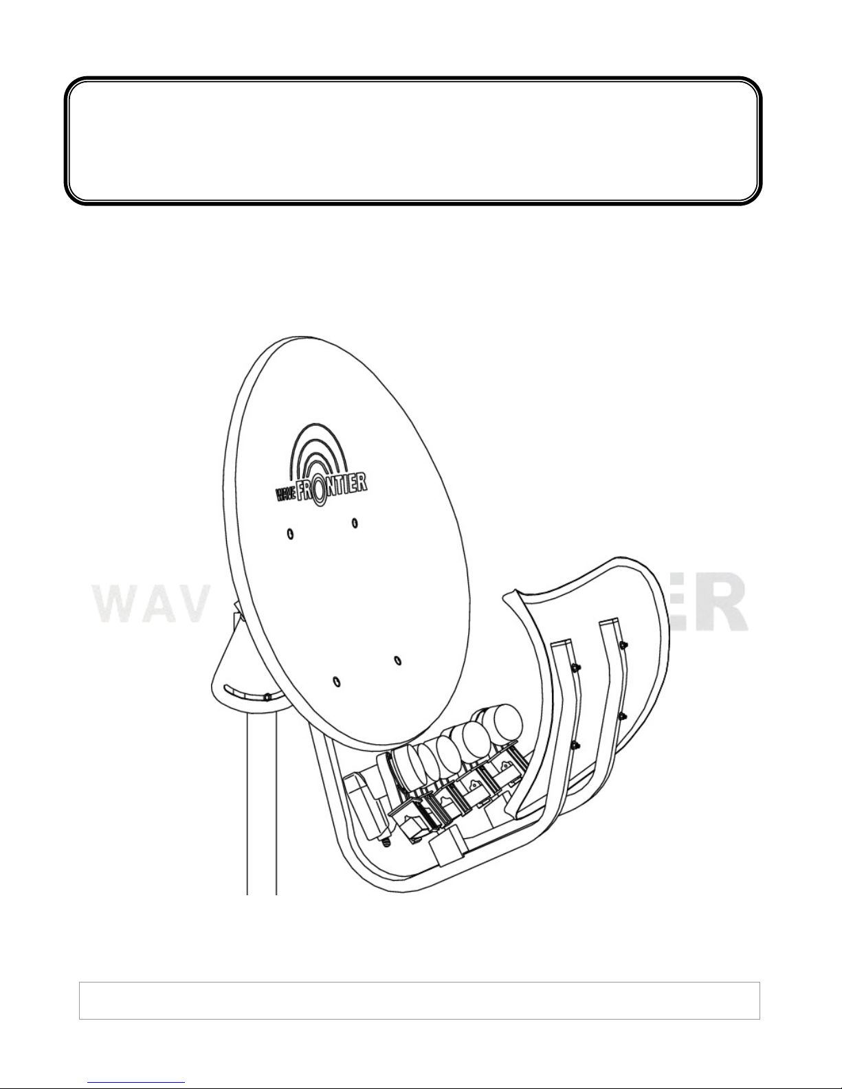
INSTALLATION MANUAL
For Toroidal 55 Multi-Beam Satellite Antenna
¯ 2004 Wave Frontier Co T55
Page 2
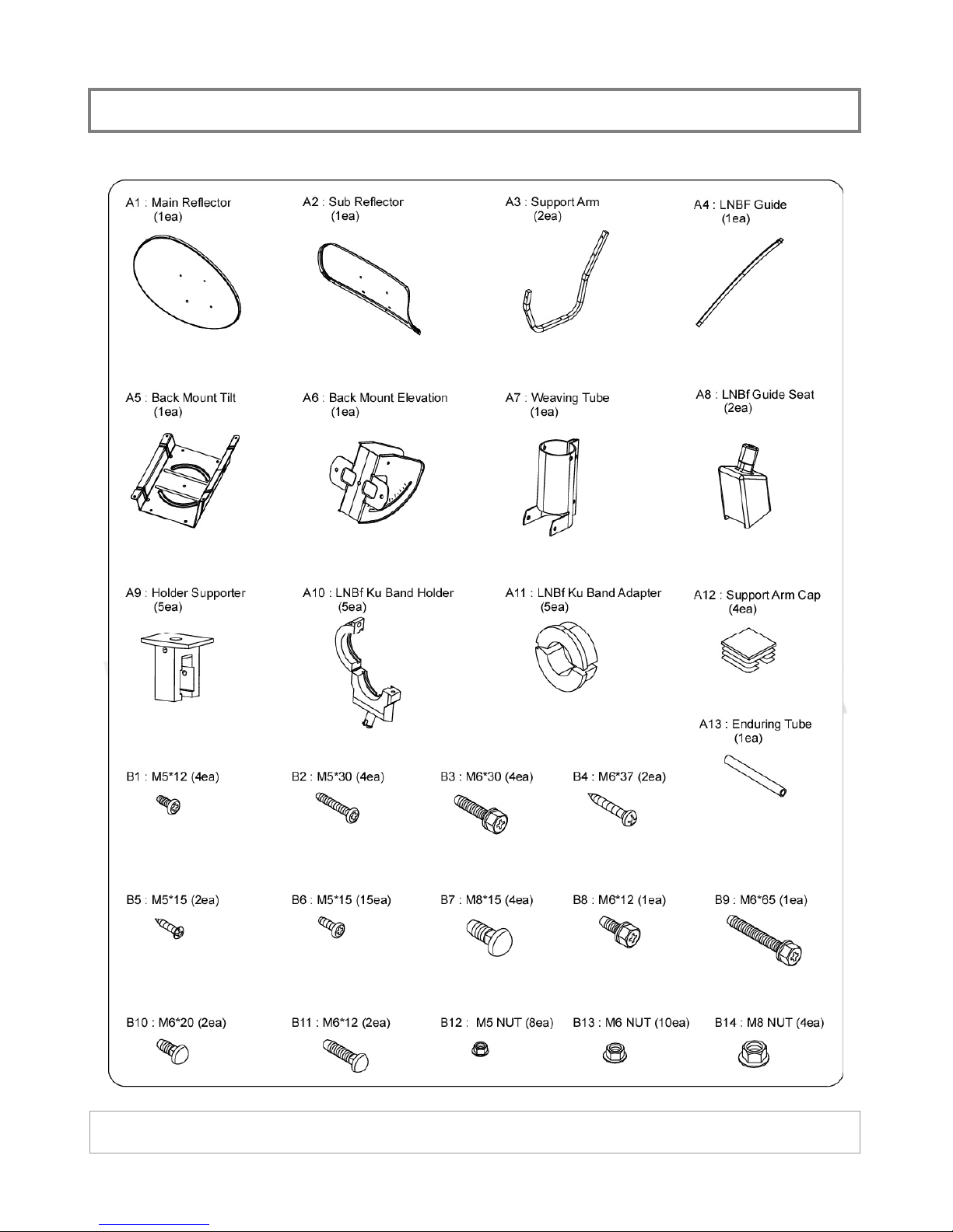
PARTS LIST
¯ 2004 Wave Frontier Co T55
Page 3
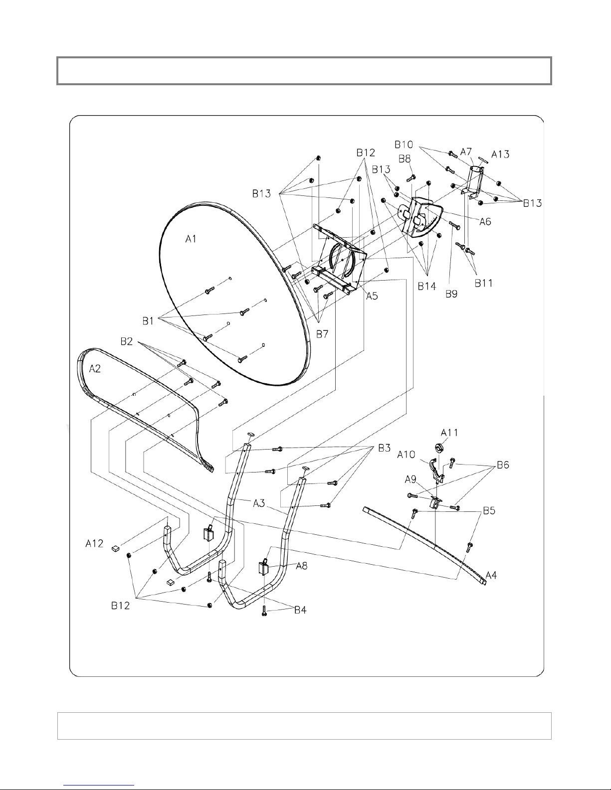
ASSEMBLY DIAGRAM
¯ 2004 Wave Frontier Co T55
Page 4
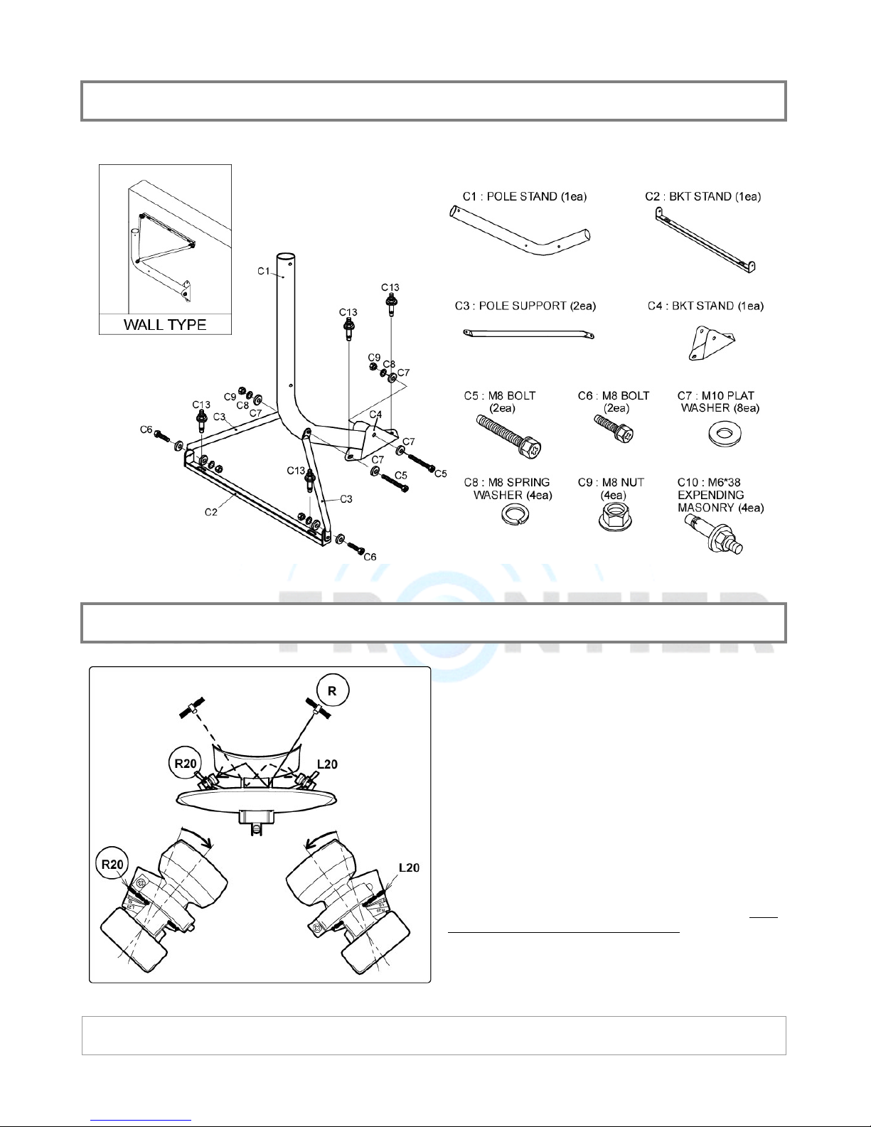
POLE MOUNT ASSEMBLY
BASIC: HOW TOROIDAL WORKS
The illustration shows how signal travels through
Toroidal. Signals are reflected twice; 1
main reflector and 2nd on the sub reflector. This is
how Toroidal can capture multiple signals within
40 degrees in arc. [In other words, you can
capture satellites from 90W ~ 130W or 60W ~
100W or 110W ~ 150.]
Please note that LNBF for your upper right satellite
(e.g. 119W) is on the left side of guide at R20 (if
you stand behind the dish).
You will find markings (from R20 to L20) on both
guide(A4) and holder supporter(A9).
st
on the
¯ 2004 Wave Frontier Co T55
Page 5
BEFORE ALIGNMENT PROCESS
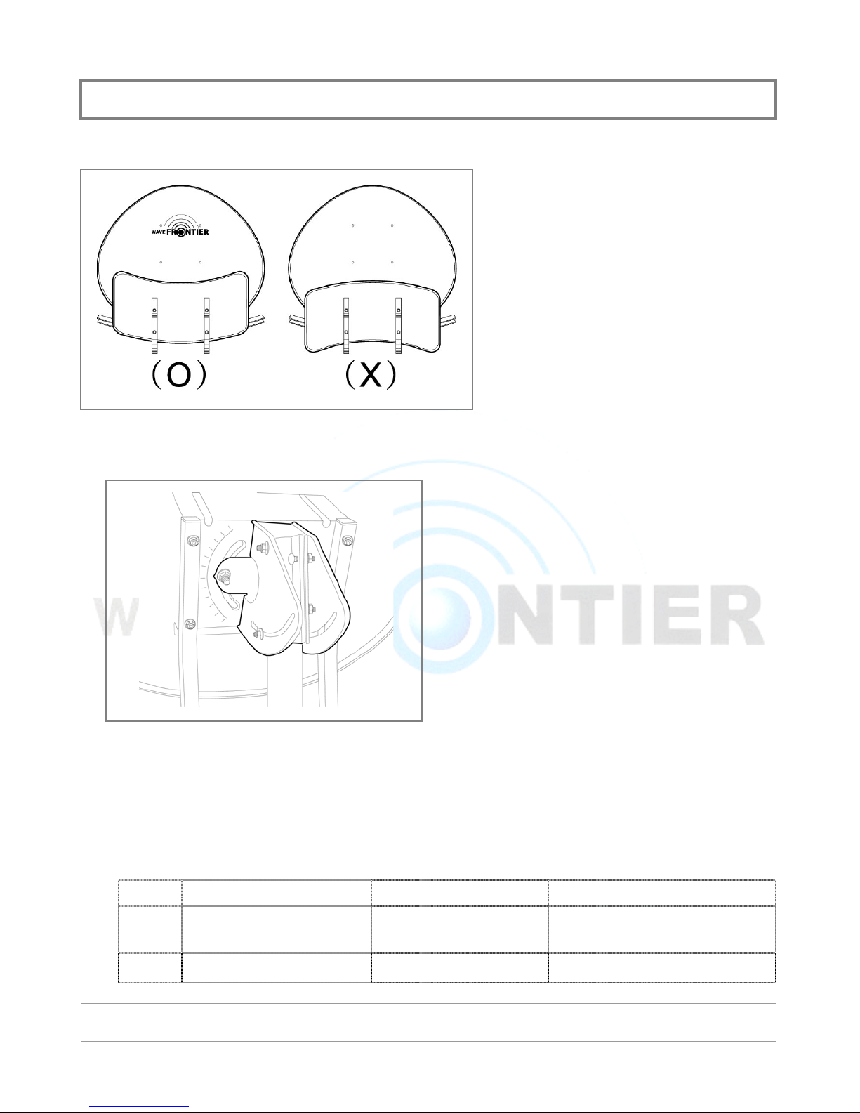
ൡ Check Your Assembly (Sub Reflector)
ൡ Check Your Assembly (Back Mount Unit)
Follow the assembly diagram to
assemble your Toroidal.
Check the orientation of your sub
reflector and guide as illustrated on the
figure.
(O) is the correct assembly of sub
reflector.
Check the orientation of back mount
unit as illustrated on the figure.
ൡ Check Your Receiver
1. Please check your receiver if it is properly working with your regular parabolic dish before
you try to connect to Toroidal.
2. Some receiver requires frequency range information in its setup process;
Model Description Frequency Range Used For
DirecTV: 101/119W
M20R Reversed DSS LNBF 12.2 Ghz ~ 12.7 Ghz
C10R Reversed Sat C LNBF 12.6 Ghz ~ 12.7 Ghz DirecTV 110W Only
DishNet: 61.5/110/119/148W
Bell Express Vu: 82/91W
¯ 2004 Wave Frontier Co T55
Page 6
PRE-ALIGNMENT: LNBF HOLDE
R
Please refer to the setup information provided
to you. If you have not received the
information, please request your zip code
specific information at the “Setup Info” section
on www.WaveFrontier.US
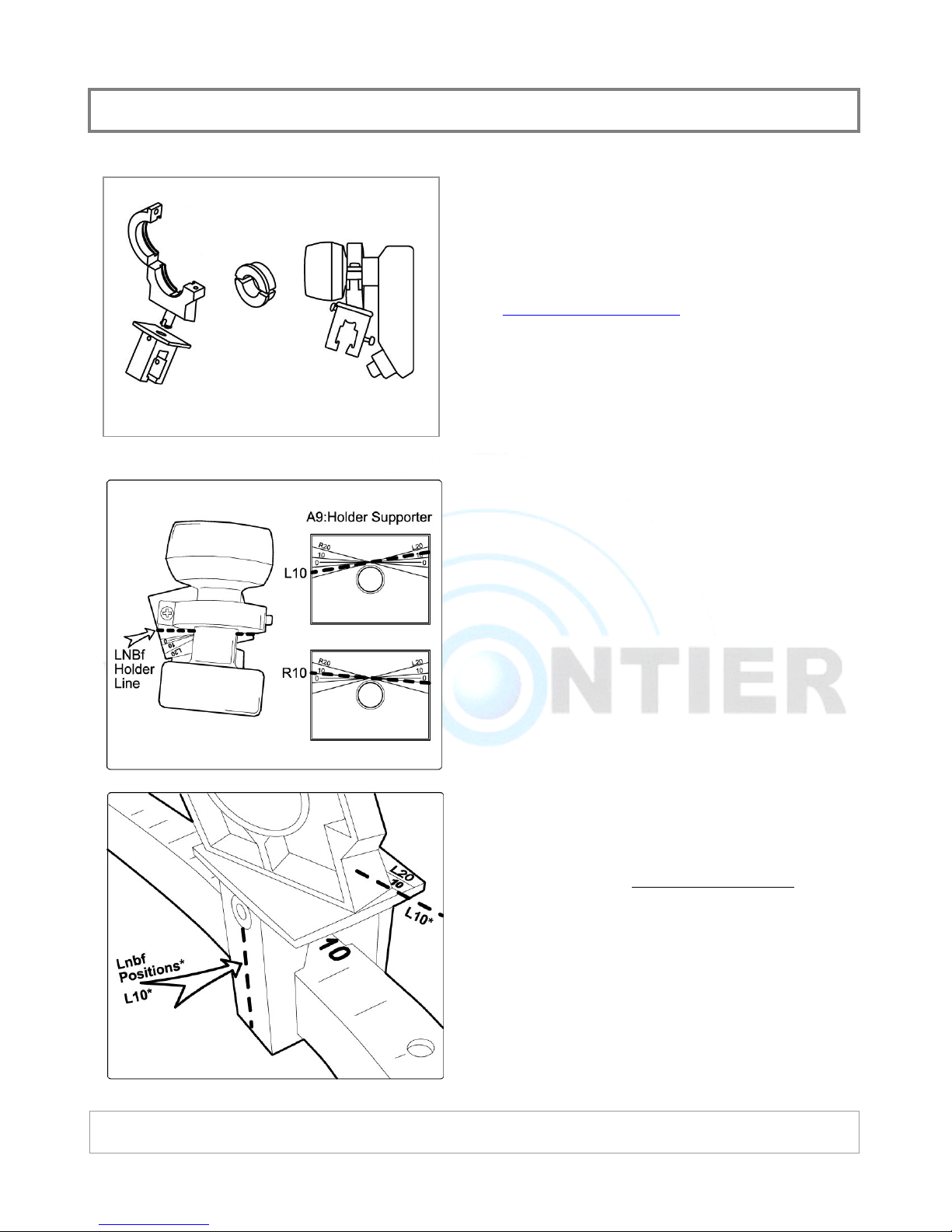
Assemble holder parts by hand at this stage.
Adapter will be required if neck size of your
LNBF is less than 40 mm.
Align the LNBF holder line to the corresponding
scale on the holder supporter. If your setup
info indicates that “A” satellite is L10, rotate
the holder till holder line reaches the L10 line
on the supporter.
.
This adjustment has a minimal impact on
signal strength. If you setup info indicates a
value with decimal number such as L14.7,
place between L10 and L20.
Place your pre-assembled holder onto the
guide. Locate the center of the holder
value give on the information. If your setup
info indicates that “A” satellite is at L10, place
the holder at L10 on the guide.
You will be making adjustment of this location
when you do the fine tuning of Toroidal
alignment at the final stage.
to the
¯ 2004 Wave Frontier Co T55
Page 7
PRE-ALIGNMENT: TOROIDAL
ൡ ELEVATION
Tip: You will be making adjustment on
elevation, skew and azimuth angles when
optimizing your setup throughout the process.
Do not use excessive force when assembling
moving parts.
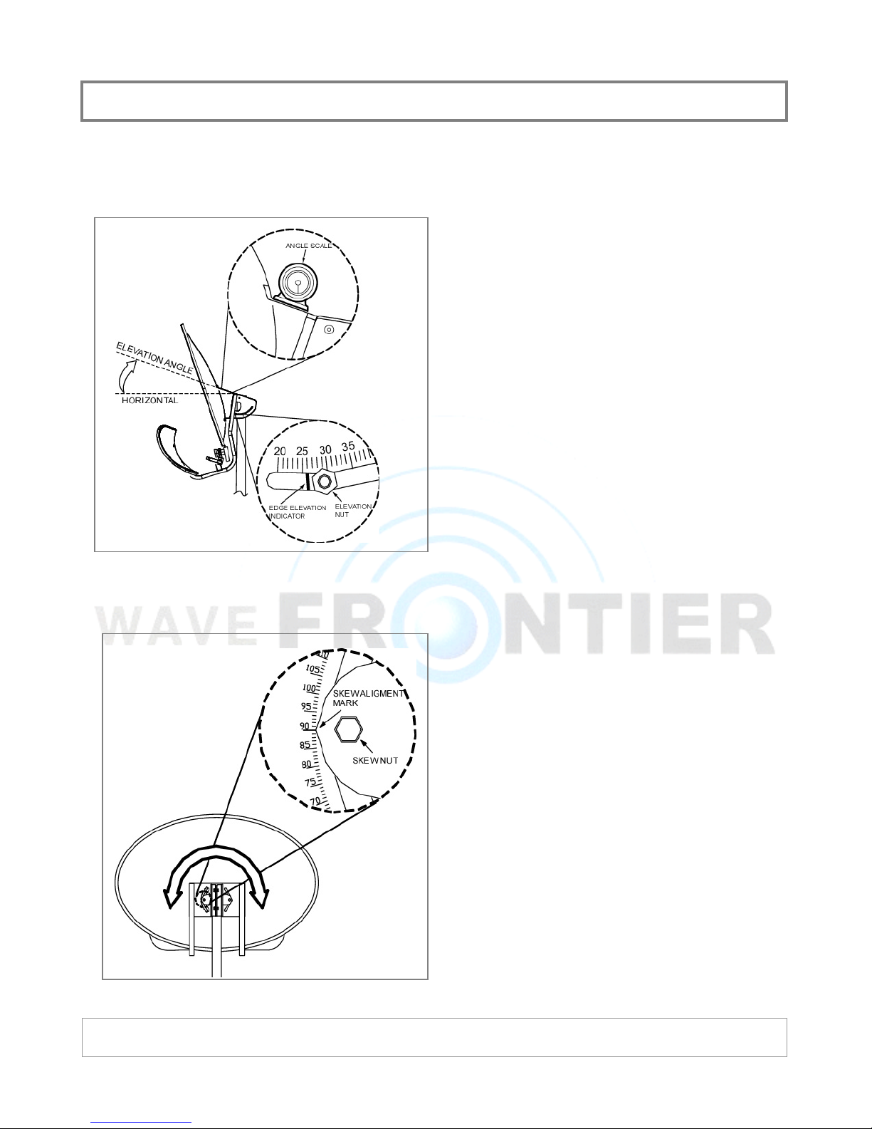
VERY IMPORTANT: Make sure that your
pole mount is in absolute vertical
position.
Use angle scale locator or adjust ‘Edge
Elevation Indicator’ to the value provided.
Note that elevation is the most important and
critical factor in aligning Toroidal dish.
ൡ SKEW
Adjust skew angle as given in the setup
information.
¯ 2004 Wave Frontier Co T55
Page 8
ALIGNMENT: TOROIDAL
ൡ TIP
If possible, align Toroidal on the ground level with your receiver and monitor right next
to Toroidal. (or use a sat finder equipment). It is MUCH FASTER, EASIER and SAFER.
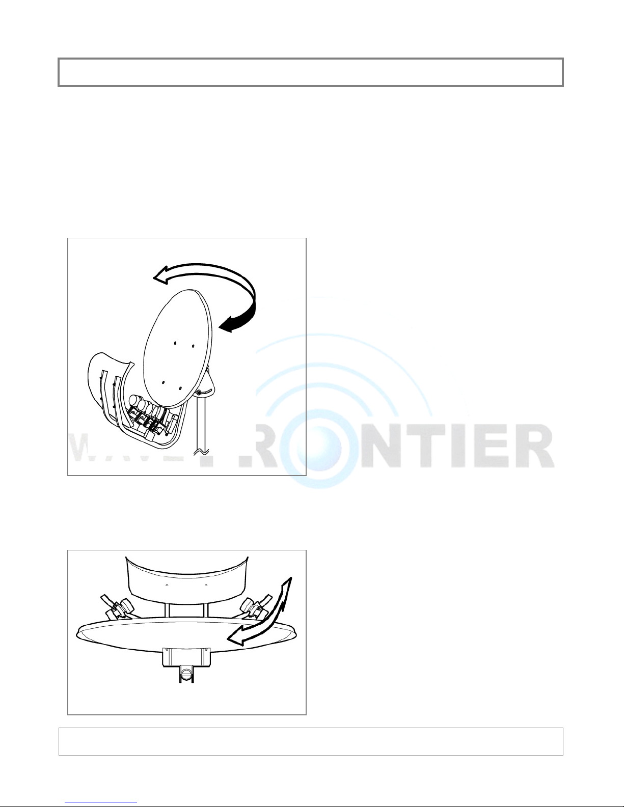
ൡ AZIMUTH SETTING
1. Connect your receiver to the center LNBF
(closest one to the center). Do not use
any switch at this point unless you are
absolutely certain that your switch and
receiver works properly.
2. Swing the dish left/right to find signal on
your center LNBF. You may also need to
adjust elevation to do this.
3. Once you found signal, do the fine-tuning
by adjusting elevation and azimuth and
check signal strength simultaneously, get
the best possible signal you can get.
ൡ LNBF LOCATION ADJUSTMENT
4. You will need to move the dish (up/down
and left/right) a little by little to get the
best signal. It will take your time and
patience.
Once you have a satisfactory signal on the
center LNBF, move on to the next LNBF.
You can also make adjustment on location of
each LNBF (except center-LNBF) to get a
better signal.
Tip: Even if your azimuth is off from the
calculated setup info, you can recover azimuth
offset by adjusting LNBF location on the guide.
¯ 2004 Wave Frontier Co T55
Page 9
FINE-TUNING: TOROIDAL
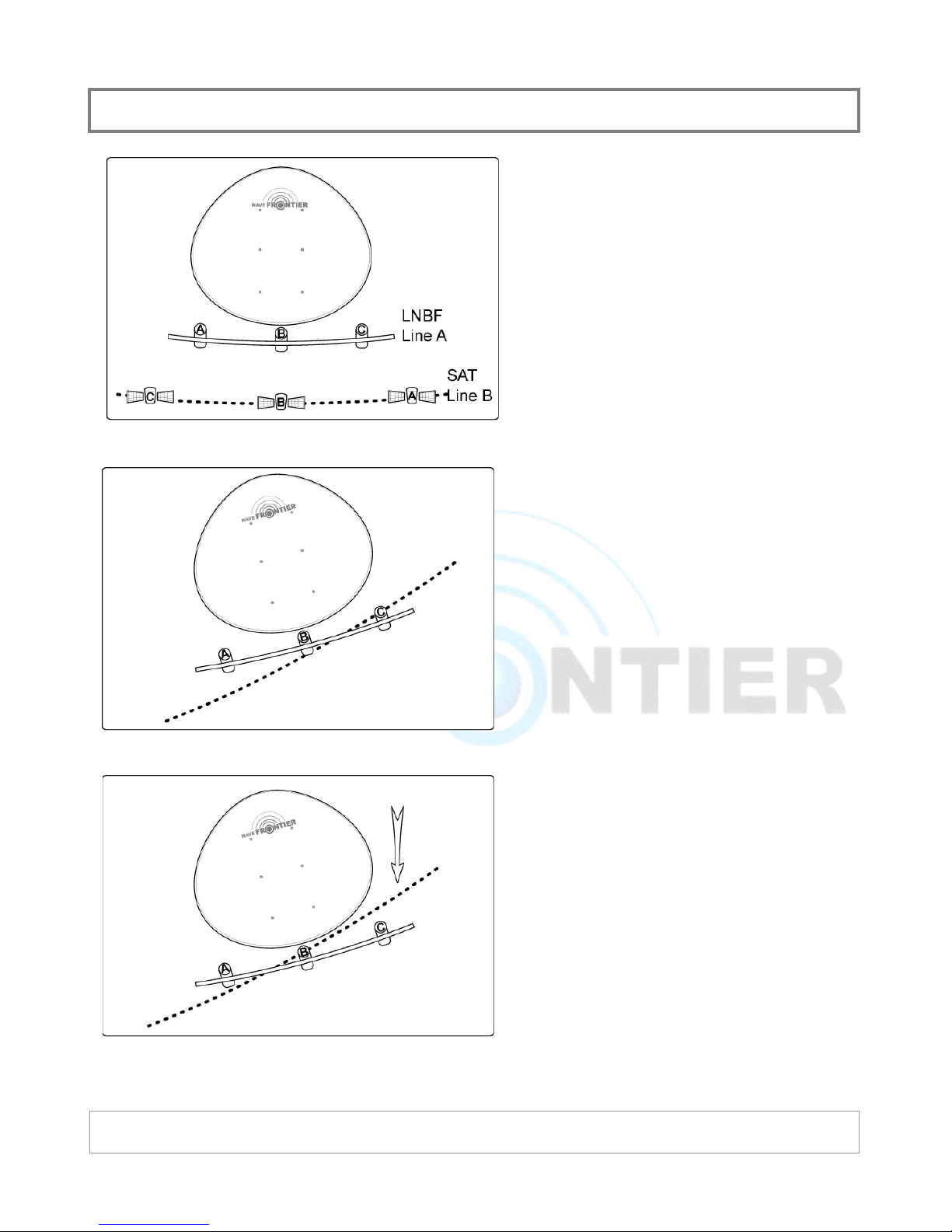
The alignment process of Toroidal is to
adjust two lines in parallel.
Assume that “A” line is formed by your
LNBFs and “B” line is formed by your target
satellites.
The alignment process of Toroidal is to
make these two lines parallel.
In reality, the line B is not a straight line.
Assume that you have 3 satellites that you
want to target.
Assume Your signal readings are as follows
after the initial alignment process;
x LNBF A: No signal
x LNBF B: 75%
x LNBF C: 95%
You will need to lower elevation since your
center-LNBF is at a higher point than the
satellite B’s focal point.
After elevation adjustment, signal readings
will be:
x LNBF A: 75%
x LNBF B: 95%
x LNBF C: 75%
Now your LNBF A is at higher point and
LNBF C is at lower point.
¯ 2004 Wave Frontier Co T55
Page 10
FINE-TUNING: TOROIDAL
R
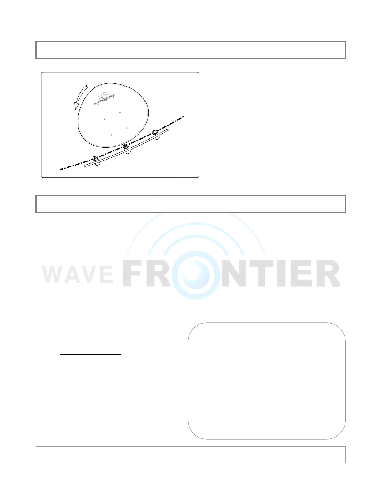
The final step would be changing a skew
angle to align A & C.
After the skew angle adjustment:
x LNBF A: 95%
x LNBF B: 95%
x LNBF C: 95%
The adjustment of skew angle is same as
adjusting the elevation angles for sat A &
C.
REGISTRATION / SERIAL NUMBE
Your Toroidal comes with 1 year manufacturer’s limited warranty. To ensure your
warranty coverage, you must do the followings:
1. REGISTER YOUR TOROIDAL
x Visit www.WaveFrontier.US
x Logo on to REGISTER section
x Provide all required information
2. KEEP SERIAL NUMBER
x Please take off the serial number
label and place this on the back of
MAIN REFLECTOR. (at the bottom
portion)
x Wave Frontier may require a customer
to submit this serial number for any
types of warranty or customer service
inquiry and may refuse warranty
request to a customer without a valid
serial number.
¯ 2004 Wave Frontier Co T55
 Loading...