

Page 1

WAVECOM Monitoring System
W-SPECTRA, W-SPEED
Manual V1.1.0
by WAVECOM ELEKTRONIK AG
Page 2

PUBLISHED BY
WAVECOM ELEKTRONIK AG
Hammerstrasse 8
CH-8180 Buelach
Switzerland
Phone +41-44-872 70 60
Fax +41-44-872 70 66
Email: info@wavecom.ch
Internet: http://www.wavecom.ch
© by WAVECOM ELEKTRONIK AG. All rights reserved.
Reproduction in whole or in part in any form is prohibited without written consent of the copyright owner.
The publication of information in this document does not imply freedom from patent or other protective rights of
WAVECOM ELEKTRONIK AG or others.
All brand names in this document are trademarks or registered trademarks of their owners.
Specifications are subject to change without further notice.
Printed: Tuesday, June 30, 2015
Page 3

Contents
General Information 2
Welcome ..................................................................................................... 2
Revisions ..................................................................................................... 2
Recommended WAVECOM Products and Services .............................................. 2
Introduction 4
W-SPECTRA ................................................................................................. 4
W-SPEED ..................................................................................................... 6
Setup 8
W-SPECTRA, W-SPEED .................................................................................. 8
Software Uninstall....................................................................................... 12
W-BV BitView Tool ............................................................................. 2
W-Sat-email-Decoder ......................................................................... 3
W-SPECTRA and W-SPEED Hardware Installation ................................... 8
Software Installation .......................................................................... 8
W-SPECTRA Server ............................................................................ 9
W-SPECTRA Licensing ...................................................................... 10
Complete Automatic Monitoring System W-SPECTRA 13
First Start .................................................................................................. 13
Default Data and Program Folders (Paths) ..................................................... 15
Main Menu ................................................................................................. 16
File Menu ................................................................................................... 18
Run Menu .................................................................................................. 18
Configuration Menu ..................................................................................... 19
Startup Preferences ......................................................................... 20
Tools Menu ................................................................................................ 20
Help Menu ................................................................................................. 22
Contents ........................................................................................ 23
License ........................................................................................... 23
WAVECOM on the Web ..................................................................... 23
About W-SPECTRA ........................................................................... 23
The Operation Tab ...................................................................................... 24
Direct Receiver Control ..................................................................... 24
Classifier, Decoder and Database Operations ...................................... 25
Wideband Spectrum Display and Media Player/Recorder ....................... 27
Narrowband Spectrum Display and Media Player/Recorder .................... 28
Display of Classification and Decoding Results ..................................... 28
User Configurable Database ......................................................................... 29
Three Operation Modes ............................................................................... 30
Direct Mode – Begin the Spectrum Monitoring ..................................... 30
Memory Scan – Revisit and Verify the Spectrum .................................. 31
Frequency Search – Automatic Spectrum Monitoring and Database
Capturing ....................................................................................... 32
Scan Delay in Automatic Modes ......................................................... 34
Summary of the Three Operation Modes ............................................. 34
Database Operations and Integrity Check ........................................... 35
Spectrum Editing Tool (W-SPEED) 37
WAVECOM Monitoring System W-SPECTRA, W-SPEED Manual V1.1.0 Contents iii
Page 4

Main Functionalities .................................................................................... 37
File Menu ................................................................................................... 38
Sonagram in Different Bandwidths ................................................................ 38
Select a Signal and Playback ........................................................................ 39
Split a Recording ........................................................................................ 40
Convert a Recording ................................................................................... 41
Parameters and Options 42
Alphabet… ................................................................................................. 42
Auto Decrypt .............................................................................................. 42
Bit Inversion Mask ...................................................................................... 43
CRC Recognition ......................................................................................... 43
CRC Table .................................................................................................. 43
Clear Screen .............................................................................................. 43
Frame Format… .......................................................................................... 44
IAS ........................................................................................................... 44
Letters/Figures... ........................................................................................ 44
Resync Mode .............................................................................................. 45
SAT Settings… ............................................................................................ 45
Timestamp ................................................................................................ 46
Display Results in a Separate Window ........................................................... 46
Auto.......................................................................................................... 47
Modulation ................................................................................................. 47
Passband Center ......................................................................................... 49
Passband Bandwidth ................................................................................... 49
Center ....................................................................................................... 49
Shift ......................................................................................................... 49
Baudrate ................................................................................................... 49
Polarity ..................................................................................................... 49
Frequency Offset ........................................................................................ 50
NB FFT Gain ............................................................................................... 50
Custom Alphabets ....................................................................................... 50
Passband Filter Support ............................................................................... 52
Transmission Modes 54
ACARS ...................................................................................................... 54
AIS ........................................................................................................... 56
ALE-400 .................................................................................................... 57
ALF-RDS .................................................................................................... 58
ALIS ......................................................................................................... 58
ALIS-2 ...................................................................................................... 59
AMSAT-P3D ............................................................................................... 60
APCO-25 ................................................................................................... 60
ARQ6-90 and ARQ6-98 ................................................................................ 61
ARQ-E ....................................................................................................... 61
ARQ-E3 ..................................................................................................... 62
ARQ-M2-342 and ARQ-M2-242 ..................................................................... 63
ARQ-M4-342 and ARQ-M4-242 ..................................................................... 63
ARQ-N ....................................................................................................... 64
ASCII ........................................................................................................ 64
ATIS ......................................................................................................... 65
AUM-13 ..................................................................................................... 66
AUTOSPEC ................................................................................................. 66
BAUDOT .................................................................................................... 67
BIIS .......................................................................................................... 68
BR-6028 .................................................................................................... 71
BULG-ASCII ............................................................................................... 72
CCIR ......................................................................................................... 73
CCITT ....................................................................................................... 74
CHINESE 4+4 ............................................................................................ 75
CHU .......................................................................................................... 75
CIS-11 ...................................................................................................... 76
iv Contents WAVECOM Monitoring System W-SPECTRA, W-SPEED Manual V1.1.0
Page 5

CIS-12 ...................................................................................................... 77
CIS-14 ...................................................................................................... 77
CIS-36 ...................................................................................................... 77
CIS-36-50 ................................................................................................. 78
CIS-50-50 ................................................................................................. 79
CLOVER-2 .................................................................................................. 79
CLOVER-2000 ............................................................................................ 80
CLOVER-2500 ............................................................................................ 81
CODAN-SELCAL .......................................................................................... 81
CODAN-9001 ............................................................................................. 81
COQUELET-13 ............................................................................................ 85
COQUELET-8 .............................................................................................. 86
COQUELET-80 ............................................................................................ 87
CTCSS ....................................................................................................... 88
CV-786 ...................................................................................................... 89
CW-MORSE ................................................................................................ 89
DCS SELCAL .............................................................................................. 90
DGPS ........................................................................................................ 91
DMR .......................................................................................................... 92
dPMR ........................................................................................................ 92
DTMF ........................................................................................................ 93
DUP-ARQ ................................................................................................... 94
DUP-ARQ-2 ................................................................................................ 95
DUP-FEC-2................................................................................................. 95
DZVEI ....................................................................................................... 96
EEA ........................................................................................................... 96
EFR ........................................................................................................... 97
EIA ........................................................................................................... 98
ERMES ...................................................................................................... 98
EURO ...................................................................................................... 101
FEC-A...................................................................................................... 101
FELDHELL ................................................................................................ 102
FLEX ....................................................................................................... 103
FM-HELL .................................................................................................. 103
FMS-BOS ................................................................................................. 104
GMDSS/DSC-HF ....................................................................................... 106
GMDSS/DSC-VHF ..................................................................................... 106
GOLAY/GSC ............................................................................................. 107
G-TOR ..................................................................................................... 108
GW-FSK .................................................................................................. 109
GW-OFDM................................................................................................ 109
GW-OFDM-Modulation and Protocol .................................................. 110
Decoder ....................................................................................... 110
GW-PSK .................................................................................................. 111
HC-ARQ ................................................................................................... 111
HF-ACARS ............................................................................................... 112
HNG-FEC ................................................................................................. 113
ICAO SELCAL ........................................................................................... 114
LINK-11 (CLEW) ....................................................................................... 115
MD-674 ASYNC ........................................................................................ 116
METEOSAT ............................................................................................... 116
MFSK-20 ................................................................................................. 117
MFSK-8 and MFSK-16................................................................................ 118
MIL-188-110-16Tone (MIL-188-110A/B Appendix B) ..................................... 118
MIL-188-110-39Tone (MIL-188-110A/B Appendix C) ..................................... 119
MIL-188-110A .......................................................................................... 120
MIL-188-110A-MOD .................................................................................. 122
MIL-188-110B (Appendix C), STANAG 4539 ................................................. 123
MIL-188-141A .......................................................................................... 125
MIL-188-141B (Appendix C) ....................................................................... 126
MIL-M-55529A NB/WB .............................................................................. 127
MOBITEX-1200 ......................................................................................... 128
MOBITEX-8000 ......................................................................................... 129
MODAT .................................................................................................... 129
WAVECOM Monitoring System W-SPECTRA, W-SPEED Manual V1.1.0 Contents v
Page 6

Fax & MODEMS Half-Duplex ....................................................................... 130
FAX-G3-V.17 ................................................................................. 130
FAX-G3-V.27ter ............................................................................. 130
FAX-G3-V.29 ................................................................................. 131
FAX-G3-V34hdx ............................................................................ 131
V.21, BELL103 .............................................................................. 131
V.22 / V.22bis, BELL212A ............................................................... 131
V.23 ............................................................................................ 131
FAX & MODEMS Full-Duplex ....................................................................... 132
V.26 / V.26bis ............................................................................... 132
V.32 / V.32bis ............................................................................... 132
V.34 ............................................................................................ 132
V.90 ............................................................................................ 132
V.92 ............................................................................................ 133
MPT-1327 ................................................................................................ 133
NATEL ..................................................................................................... 135
NMT-450 ................................................................................................. 136
NOAA-GEOSAT ......................................................................................... 136
NWR-SAME .............................................................................................. 137
NXDN ...................................................................................................... 141
OLIVIA .................................................................................................... 141
ORBCOMM ............................................................................................... 142
PACKET-1200 ........................................................................................... 143
PACKET-300 ............................................................................................ 144
PACKET-9600 ........................................................................................... 144
PACTOR ................................................................................................... 145
PACTOR-FEC ............................................................................................ 146
PACTOR-II ............................................................................................... 147
PACTOR-II-AUTO ...................................................................................... 148
PACTOR-II-FEC ........................................................................................ 148
PACTOR-III .............................................................................................. 149
PCCIR ..................................................................................................... 150
PDZVEI ................................................................................................... 151
PICCOLO-MK6 and PICCOLO-MK12 ............................................................. 152
POCSAG .................................................................................................. 153
POL-ARQ ................................................................................................. 155
PRESS-FAX .............................................................................................. 155
PSK-10 .................................................................................................... 156
PSK-31, PSK-63, PSK-125, PSK-250 ........................................................... 156
PSK-31-FEC ............................................................................................. 157
PSK-63F, PSK-125F, PSK-220F ................................................................... 158
PSK-AM ................................................................................................... 159
PZVEI ...................................................................................................... 159
ROBUST-PACKET ...................................................................................... 160
RUM-FEC ................................................................................................. 161
SAT-AERO ............................................................................................... 162
SAT-B ..................................................................................................... 162
SAT-B-C-TFC ............................................................................................ 163
SAT-B-C-HSD ........................................................................................... 164
SAT-C-TDM, SAT-C-TDMA, SAT-C-EGC ........................................................ 165
SAT-C TDM ................................................................................... 165
SAT-C-TDMA ................................................................................. 166
SAT-C-TDM-EGC ............................................................................ 167
SAT-M ..................................................................................................... 169
SAT-MINI-M ............................................................................................. 169
SAT-MINI-M-C-HSD .................................................................................. 170
SI-ARQ .................................................................................................... 171
SI-AUTO .................................................................................................. 171
SI-FEC .................................................................................................... 172
SITOR-ARQ .............................................................................................. 172
SITOR-AUTO ............................................................................................ 173
SITOR-FEC............................................................................................... 173
SP-14 ...................................................................................................... 173
SPREAD-11, SPREAD-21 and SPREAD-51 ..................................................... 175
vi Contents WAVECOM Monitoring System W-SPECTRA, W-SPEED Manual V1.1.0
Page 7

SSTV ....................................................................................................... 175
STANAG-4285 .......................................................................................... 177
STANAG-4415 .......................................................................................... 179
STANAG-4481-FSK ................................................................................... 180
STANAG-4481-PSK ................................................................................... 181
STANAG-4529 .......................................................................................... 182
STANAG-4539 .......................................................................................... 184
STANAG-5065-FSK ................................................................................... 184
SWED-ARQ .............................................................................................. 184
TETRA ..................................................................................................... 185
Constraints ................................................................................... 188
THROB and THROBX ................................................................................. 189
TWINPLEX ............................................................................................... 190
VDEW ..................................................................................................... 191
VDL-M2 ................................................................................................... 192
VISEL ...................................................................................................... 193
WEATHER-FAX ......................................................................................... 193
X.25........................................................................................................ 194
ZVEI-1 .................................................................................................... 195
ZVEI-2 .................................................................................................... 196
ZVEI-3 .................................................................................................... 197
ZVEI-VDEW ............................................................................................. 197
Classifier – the Brain of W-SPECTRA 200
Overview ................................................................................................. 200
Classifier ................................................................................................. 200
How the Classifier Works ................................................................ 200
Classification Results List ................................................................ 201
Classifier Parameters ..................................................................... 202
Caveats ........................................................................................ 203
Technical Data of the Narrowband and Wideband Classifier ................. 204
Classifier Code Check HF/VHF/UHF (CCC) .................................................... 206
How the Classifier Code Check Works ............................................... 206
User Interface ............................................................................... 208
Decoding ...................................................................................... 211
Scan Delay in Automatic Modes ....................................................... 211
Classifier Code Check Editor ....................................................................... 211
Installation ................................................................................... 211
CCC Editor GUI.............................................................................. 212
Database Fields ............................................................................. 216
SAT System 219
Overview ................................................................................................. 219
Systems .................................................................................................. 220
RF Channels .................................................................................. 221
Logical Channels............................................................................ 221
MES Identification .......................................................................... 222
Session Signaling .......................................................................... 222
SAT Operation .......................................................................................... 222
Traffic-Channel Decoder ................................................................. 224
The Sat Aero System ................................................................................ 224
Services ....................................................................................... 224
Channel types ............................................................................... 225
Trouble Shooting ........................................................................... 226
Modem and FAX Modes 230
Overview ................................................................................................. 230
Line transmission .......................................................................... 230
Fax and Data Transmission ........................................................................ 231
Modem Functionality ...................................................................... 231
Handshaking ................................................................................. 232
WAVECOM Monitoring System W-SPECTRA, W-SPEED Manual V1.1.0 Contents vii
Page 8

Modulation Types .......................................................................... 233
Decoding ................................................................................................. 234
Input and interfacing ..................................................................... 236
Constraints ................................................................................... 236
Output ......................................................................................... 237
License System, Software and Options 238
License System ........................................................................................ 238
CmStick .................................................................................................. 238
CodeMeter and CmStick User Guide (Help) ....................................... 239
License update for CodeMeter and CmStick ....................................... 239
WAVECOM Data Formats 240
IP-CONF TCP/IP Data Format ..................................................................... 240
IP-PXGF TCP/IP Data Format ...................................................................... 240
OVERVIEW.................................................................................... 240
PXGF DESCRIPTION ....................................................................... 240
THE PXGF CHUNK STRUCTURE ........................................................ 240
APPLICATION NOTES ..................................................................... 241
DEFINITION OF CHUNKS ................................................................ 242
WAVECOM Data File Format ....................................................................... 244
File Header ................................................................................... 244
Data Structures ............................................................................. 245
File Headers and Data Structures for Individual File Types .................. 245
Appendix 253
Alphabets Details ...................................................................................... 253
Unicode ........................................................................................ 253
Questions & Answers................................................................................. 263
Signal Interference ................................................................................... 263
General ........................................................................................ 263
Antenna installation ....................................................................... 264
Receiver ....................................................................................... 264
HF cabling .................................................................................... 264
Grounding .................................................................................... 264
Location of decoder ....................................................................... 264
PCs and peripherals ....................................................................... 264
Video monitor ............................................................................... 264
LAN ............................................................................................. 264
Conditions of Sale ..................................................................................... 264
General ........................................................................................ 264
Prices ........................................................................................... 265
Delivery time ................................................................................ 265
Dispatch ....................................................................................... 265
Return of goods ............................................................................. 265
Payment ....................................................................................... 265
Reservation of ownership ............................................................... 265
Cancellation .................................................................................. 265
Changes of order quantities ............................................................ 265
Legal domicile ............................................................................... 265
Warranty ...................................................................................... 266
Obligation ..................................................................................... 266
Copyright ..................................................................................... 266
Liability ........................................................................................ 266
Laws and regulations ..................................................................... 266
License Terms .......................................................................................... 266
Manufacturer Address ............................................................................... 267
Glossary of Terms 269
Index 279
viii Contents WAVECOM Monitoring System W-SPECTRA, W-SPEED Manual V1.1.0
Page 9

WAVECOM Monitoring System W-SPECTRA, W-SPEED Manual V1.1.0 Contents ix
Page 10

Page 11

WAVECOM Monitoring System W-SPECTRA, W-SPEED Manual V1.1.0 General Information 1
Page 12

Version
Date
Changes
1.0.0
05-Jan-2015
Launch of W-SPECTRA and W-SPEED.
1.1.0
06-Jun-2015
New features and functionalities in W-SPECTRA and W-SPEED.
General Information
Welcome
Thank you for choosing Wavecom monitoring system and decoder product. The product that you have
purchased includes the latest technology in data decoding, together with the latest software release available at the time of shipment.
Please check our website at http://www.wavecom.ch for software updates.
Before you install the product, please also check the latest documentation on the installation DVD or on
our website.
WAVECOM ELEKTRONIK AG develops and sells products for wireless (HF/VHF/VHF/SHF) data monitoring in
all frequency bands.
Our main decoder and monintoring product series are:
W-SPECTRA is a complete automatic spectrum monitoring system over all frequency bands
(HF/VHF/UHF/SHF).
W-PCI and W-PCIe are hardware decoders with two physically independent channels. W74PC is
hardware decoder with four physically independent channels.
W-CODE is a stand-alone software decoder working with native host hardware, like a built-in
soundcard or other audio devices.
All hardware decoders (W-PCI, W-PCIe and W74PC) and the software decoder W-CODE have the
same decoding functionalities.
W-PCI-LAN and W-PCIe-LAN are hardware decoders running in a ruggedized mobile computer.
They are a complete data decoding system.
Revisions
Recommended WAVECOM Products and Services
W-BV BitView Tool
The highly sophisticated BitView Tool is an external off-line, stand-alone .NET application for analysis of
unknown signals.
BitView has a number of features:
Bit manipulation tools
Bit display tools (text, graphics)
Simultaneous processing of multiple analysis sessions
Auto-update functionality
Report generator (parameters, data, ASCII, XML)
Drag and drop of functions
2 General Information WAVECOM Monitoring System W-SPECTRA, W-SPEED Manual V1.1.0
Page 13

Email system
Recognize
Decode
AMOS
Y
Y
Blast
Y
N
Dualog
Y
Y
GlobeWireless
Y
Y
GTMail
Y Y MS-RAS PPP
Y
Y
MS-RAS TCP/IP
Y
N
Rydex
Y
Y
se@comm
Y
Partially
SkyFile
Y Y UUCP
Y Y UUPlus
Y Y Xdatos
Y
Partially
ZModem
Y
Y
Re-arrangement of functions in a tree view
Nested docking
Auto hide
Drag and drop of windows
Application and modification of alphabets
Persistent-to-XML file (screen layout is restored at start-up time)
.NET technology
No installation required, just run the executable
Data stream and data file import from W61PC/LAN, W-PCI, W-PCIe and W-CODE
MatLab and C# user defined functions
W-Sat-email-Decoder
The W-Sat-email-Decoder takes as its input a session file and the corresponding text files, as produced by
a WAVECOM decoder, or any text file from an external source containing emails. It does protocol decoding
and decompression, the email(s) and possible attachment(s) are output as files. The following email systems will be recognized and decoded respectively.
WAVECOM Monitoring System W-SPECTRA, W-SPEED Manual V1.1.0 General Information 3
Page 14

Introduction
W-SPECTRA
In the modern data communication and signal intelligence the user requires more and more a complete
automatic system which monitors certain frequency bands, fullfills the following main tasks:
It controls the receiver directly, set the receiver frequency, demodulator and demodulator band-
width, etc.
It classifies and decodes signals automatically.
It records the results of classification and decoding into a database.
It records the spectrum in a wide bandwidth, so that the user can analyse the whole spectrum af-
terwards.
W-SPECTRA is exactly such a system to meet these major demands. W-SPECTRA provides:
Comprehensive online (real-time) monitoring functions, running through the entire radio spec-
trum from ELF to SHF
Intuitive graphical user interface: its main operation tab covers all online monitoring activities
Built-in bi-directional control of receivers (WiNRADiO G3xDDC)
Three monitoring modes: Direct Mode, Memory Scan and Frequency Search
More than 220 mode decoders and protocols over HF/VHF/UHF/SHF
Wideband (2 MHz) and narrowband (96 kHz) FFT and sonagram displays
Wideband (2 MHz) and narrowband (96 kHz) signal recording in baseband (IQ) and signal play-
back
Signal recording is made with various important side information (meta-data) on-the-fly, such as
the receiver frequency, bandwidth and timestamp for complete investigation of the whole spectrum after the online monitoring
Automatic demodulation and decoding of known signals to the content level
Automatic search, classification and code check of signals over a user-defined frequency band and
certain search strategy
Automatic or manual capturing of results into a database
Display of classification and decoding results in a separate window
Classification and decoding results can be saved into files as well
User configurable database template
Database in XML format, providing easy processing by third-party applications
Integrity check of the database
Wideband spectrum editing: display a wideband IQ recording in a 2-dimensional sonagram,
zoom-in view of the sonagram and cut out a signal anywhere (in time and frequency domains)
from a wideband IQ recording for classification and decoding afterwards.
A typical configuration of an automatic spectrum monitoring system with W-SPECTRA can look like the following:
4 Introduction WAVECOM Monitoring System W-SPECTRA, W-SPEED Manual V1.1.0
Page 15

Example setup of a monitoring system with W-SPECTRA.
W-SPECTRA connects to a Software Defined Radio (SDR) and takes over its full control. A built-in mass
storage device (e.g., an SSD) can be used by W-SPECTRA for wideband IQ signal recording.
All important operation activities are covered in the W-SPECTRA GUI “Operation” tab:
Receiver control: allows the bi-directional setting of the receiver frequency, demodulator, demodu-
lator bandwidth and AGC etc.
Choose a classifier or a decoder manually or automatically
Display the classification result into a database entry
Database operations: insert, overwrite and manually edit an entry
Wideband spectrum display (2 MHz) with IQ signal recording and playback
Narrowband spectrum display (96 kHz) with IQ signal recording and playback
Display detailed classification and decoding result
Switch among the three operation modes: Direct Mode, Memory Scan and Frequency Search
Four buttons (Start, Stop, Previous and Next) control the work flow of the three operation modes.
WAVECOM Monitoring System W-SPECTRA, W-SPEED Manual V1.1.0 Introduction 5
Page 16

W-SPECTRA GUI Operation tab contains five parts: direct receiver control, classifier and decoder setting,
wideband spectrum display and media player/recorder, narrowband spectrum display and media player/recorder and classification and decoding result display.
W-SPEED
While running online (real-time) spectrum monitoring, a system (e.g., W-SPECTRA) can usually classify
and decode signals in a limited bandwidth in real-time (online). The reasons are usually limited processing
bandwidth of certain components and limited computation power. Signals outside the processing bandwidth can not be processed online. To solve this problem W-SPECTRA makes a recording of signals in a
much wider bandwidth than it can process online. The recording is done in a lossless way, usually in baseband IQ and the recorded signal is processed afterwards by the Spectrum Editing tool W-SPEED.
W-SPEED loads a recorded signal and displays it in a two-dimensional sonagram with the frequency as the
x-axis and time as the y-axis. The sonagram display bandwidth is selectable among 250 kHz, 500 kHz, 1
MHz, 1.5 MHz, 2 MHz, 4 MHz, 8 MHz, 10 MHz, 12 MHz, 16 MHz and 24 MHz, with 2 MHz as default. The
user can examine the sonagram by zooming-in to and navigating over the spectrum, mark an interesting
signal and send this signal to W-SPECTRA or other Wavecom decoders (e.g., W-CODE) for classification
and decoding.
A typical setup of this spectrum investigation is as in the following
6 Introduction WAVECOM Monitoring System W-SPECTRA, W-SPEED Manual V1.1.0
Page 17

Example setup of the Wavecom spectrum editing tool W-SPEED working together with the monitoring system W-SPECTRA. The user can select a 96 kHz wide signal stripe and send it to W-SPECTRA for detail investigation.
WAVECOM Monitoring System W-SPECTRA, W-SPEED Manual V1.1.0 Introduction 7
Page 18

Click the “W-SPECTRA” button to install the WSPECTRA application.
First, you will see the welcome screen. Click
“Next” to continue the installation.
Setup
W-SPECTRA, W-SPEED
The automatic monitoring system W-SPECTRA and the spectrum editing tool W-SPEED provide all functions required to analyse, classify, decode and process radio data communications over the entire frequency spectrum. Both are licensed software, running on existing equipments of the customer. This feature allows seamless integration with SDR (Software Defined Radio) receivers with IQ data and TCP/IP data outputs. The license for the software is programmed on a CmStick USB key. One client license is provided with each software package (multiple licenses on request).
W-SPECTRA and W-SPEED Hardware Installation
Insert the USB license key(s) in any USB socket.
Software Installation
W-SPECTRA supports the WiNRADiO Software Defined Radio (SDR) receivers G3xDDC. Before the user install W-SPECTRA please make sure that the G3xDDC software is already installed.
Insert the WAVECOM installation DVD in the drive. When requested, point the auto start wizard to the disc
drive and start installation.
Note: To run installation you need to have the Administrator right. After installation, you can run the
applications W-SPECTRA and W-SPEED if you are a member of the Administrators, Power Users or Us-
ers group.
Before the installation of a software update, the old version must be uninstalled (see “Software Uninstall”
on page 12). After uninstallation has completed, insert the WAVECOM installation disc in the drive; the installer will start automatically. Otherwise, it can be started with Windows Explorer by double-clicking
Installation.exe.
Without loosing generality we show the installation steps on the example W-SPECTRA.
The selection dialogue of the installation program is displayed:
8 Setup WAVECOM Monitoring System W-SPECTRA, W-SPEED Manual V1.1.0
Page 19

Change the destination folder and click “Next” to
continue the installation.
Click “Next” to continue the installation.
Wait until the installation is finished.
If the installation was successful, click Fin-
ish to complete the process.
Note: If a firewall is enabled on your system, depending on its security level settings, various components
of W-SPECTRA may ask to access the Internet or the trusted zone of the firewall. You will have to manually grant access to these components.
Check for hidden windows if the installation process seems to “hang” (this can be done by pressing the
Alt+Tab keys). Sometimes windows in the background are waiting for a button to be pressed to allow the
installation to proceed.
W-SPECTRA Server
W-SPECTRA runs in a client/server architecture. The W-SPECTRA server is running as a Windows service,
which will start automatically at the PC startup. The corresponding tray icon indicates the server status as
below.
Status of the W-SPECTRA server.
Make sure that the server is in “running” status. The user can also start the server manually by right clicking the mouse or just double clicking the desktop icon “W-SPECTRA”.
WAVECOM Monitoring System W-SPECTRA, W-SPEED Manual V1.1.0 Setup 9
Page 20

W-SPECTRA Licensing
The license of W-SPECTRA is programmed on a USB key (Wibu CmStick). The software is delivered with
one year free update, i.e., the customer will get new software versions free of charge during one year after the date of purchase. The update period can be extended for max. 5 years. The purchased software
version itself runs without time limit.
On request, different licensing models are available:
Single-user licenses
Network licenses with floating licenses (sharing of W-SPECTRA and options between different
computers)
Licenses for other WAVECOM software products and third party products may also be stored on
the CmStick
Software Updates
Software released during the update period can be installed at any time.
New licenses can be loaded to the CmStick without sending the physical USB key to WAVECOM. Just click
License Update on the CodeMeter Control Center and follow the information provided by the assistant.
How to update a license.
Software Options
W-SPECTRA runs in two different bandwidth variants: narrowband (W-SPECTRA-NB, with a 8 kHz narrowband classifier CLNB) or wideband (W-SPECTRA-WB, with a 96 kHz wideband classifier CLWB) (see
“License System, Software and Options” on page 238).
Both classifiers are delivered with separate license codes. The classifier licenses can also be shared by
other Wavecom decoders, e.g., W-CODE. If the customer already has a classifier license, he can just order
the W-SPECTRA without specifying the bandwidth. In this case W-SPECTRA will run with the existing classifier license.
To order the W-SPECTRA software, please follow this procedure:
Place an order W-SPECTRA with the bandwidth option (narrowband or wideband). If you already
have a CmStick, you may give us the serial number of your CmStick.
WAVECOM will process your order and forward an invoice.
After the payment has been received, a new key or license file for your existing CmStick will be
forwarded.
10 Setup WAVECOM Monitoring System W-SPECTRA, W-SPEED Manual V1.1.0
Page 21

Press the “WebAdmin”.
Licenses available on the CmStick are listed in
this screen.
Item
Remarks
Product
Code
Displays the product code
Name
Displays the name of the product item, normally the name of the product
Feature Map
Displays the feature map
Licenses
Displays the total number of network licenses
Maintenance
Period
Display the maintenance period of the license. Wavecom uses this to check whether the
license is valid to run a new software version
User Limit
Displays the number of licenses, which are currently used in the user limit mode
No User
Limit
Displays the number of licences that are currently used in the no user limit mode
Exclusive
Displays the number of licences that are currently used in the exclusive mode
Shared
Displays the number of licences that are currently used in the shared mode
Free
Displays the number of licences that are currently free
Details
Displays detailed information about the respective network licences in use
To process an order for options, the following information is required:
Complete address
Ordered items
Email or mail delivery
Serial number and remote context file of CmStick to be updated, if applicable
W-SPECTRA License Checking
To check the license(s) on the CmStick follow these steps:
Open the CodeMeter WebAdmin interface from the CodeMeter tray icon.
Important: If you have multiple CmSticks plugged into computers in the same local network, refer to
WAVECOM Monitoring System W-SPECTRA, W-SPEED Manual V1.1.0 Setup 11
Page 22

VISTA
XP
Windows 7
Click on Start, go to
the Computers menu
and click the Unin-
stall or change a
program button
Select WAVECOM W-
[XX] from the list
Click Uninstall
Click on Start, go to the
Settings menu and open
Control Panel
Select the Add/Remove
Programs icon
Select Install/Uninstall
Choose WAVECOM W-
[XX] from the list
Click Add/Remove
Click on Start and open the
Control Panel
Select the Programs icon
Select Programs and Fea-
tures
Choose WAVECOM W-[xx]
from the list
Click Uninstall in the menu
“License System, Software and Options” on page 238.
Software Uninstall
In certain situations, e.g., when updating the application, it is necessary to uninstall the software. Use the
following commands:
The application has now been removed from the PC - it is possible, however, that the shortcut icons may
have to be removed manually.
12 Setup WAVECOM Monitoring System W-SPECTRA, W-SPEED Manual V1.1.0
Page 23

Complete Automatic Monitoring
System W-SPECTRA
First Start
After the software and the CmStick have been successfully installed, W-SPECTRA can be started
either from the Windows Start menu or by double-clicking the program icon on your desktop.
Start the WiNRADiO G3xDDC receiver as well. For example,
WiNRADiO G39DDC native GUI.
Proper operation of W-SPECTRA is indicated by the WAVECOM Server Control icon in the Windows
system tray in the taskbar. If the the icon is green, the server is operating normally. You may also
move the mouse over the icon and check that you get this status message: WAVECOM Server –
W-SPECTRA (running).
The following GUI shows that W-SPECTRA is running properly. It is connected to an SDR and is
classifying signals coming from the receiver.
WAVECOM Monitoring System W-SPECTRA, W-SPEED Manual V1.1.0Complete Automatic Monitoring System WSPECTRA 13
Page 24

W-SPECTRA works properly.
There are five major parts in the W-SPECTRA main GUI:
o Direct receiver (SDR) control
o Run a decoder or a classifier, database operations
o Wideband (2 MHz) spectrum display and media player/recorder
o Narrowband (96 kHz) spectrum display and media player/recorder
o Decoder or classifier setting and display of results.
The user can set the receiver frequency, demodulator and demodulator bandwidth using the W-
SPECTRA GUI or the native SDR GUI, e.g., WiNRADiO G39DDC GUI. Settings will be synchronised
in both GUIs.
The user can view the spectrum up to 2 MHz in the wideband display.
The signals in the middle 96 kHz wide stripe of the wideband display will be shown in the narrow-
band spectrum display. The user may move the middle cursor in the narrowband display to locate
the signal.
The user may choose a classifier or decoder in the pull-down list “Mode” and the signal will be
classified or decoded. The result will be displayed in the lower part of the GUI.
If no receiver (SDR) is running or the W-SPECTRA server stops, warning messages will be dis-
played in the W-SPECTRA GUI. The user may take actions according to the message guide.
14 Complete Automatic Monitoring System W-SPECTRAWAVECOM Monitoring System W-SPECTRA, WSPEED Manual V1.1.0
Page 25

If the receiver is not running or the W-SPECTRA server stops, warning mes-
sages will appear. The user may take corresponding actions.
Default Data and Program Folders (Paths)
To see all folders, select Folder Options in the Control Panel
Enable Show all folders.
Enable Show hidden files, folders and drives
Path names can vary if you use a non-English language operating system or if you are not using the Microsoft “Windows Explorer”.
WAVECOM Monitoring System W-SPECTRA, W-SPEED Manual V1.1.0Complete Automatic Monitoring System WSPECTRA 15
Page 26

Folder
XP
Vista
Program Folder (Read only,
RO)
C:\Program Files\WAVECOM\<Product>\
C:\Program Files\WAVECOM\<Product>\
Global Data
(Read only,
RO)
C:\Documents and Settings\All Users\Application Data\WAVECOM\<Product>\
C:\ProgramData\WAVECOM\<Product>\
Global Data
(Read & write,
RW)
C:\Documents and Settings\All Users\Documents\WAVECOM\<Product>\
C:\Users\Public\Public Documents\
WAVECOM\<Product>\
User Specific
Roaming Data
C:\Documents and Settings\\<Username>\\Application Data\
WAVECOM\<Product>\
C:\Users\<Username>\AppData\Roaming\
WAVECOM\<Product>\
User Specific
Non-Roaming
Data
C:\Documents and Settings\<Username>\Local Settings\Application
Data\WAVECOM\<Product>\
C:\Users\<Username>\AppData\Local\
WAVECOM\<Product>\
Program Folder
Global Data (RO)
Global Data (RW)
Main Menu
The main menu includes all submenus relating to operating modes, as well as setup, analysis, classification, decoding and database functions.
The WINDOWS operating system is based on a multitasking kernel and can handle several tasks simultaneously, and therefore interaction with the menu system will not interrupt the execution of an active function. This allows, for example, the integrity check of a database running without interrupting other activities.
W-SPECTRA Main GUI Screen Display
16 Complete Automatic Monitoring System W-SPECTRAWAVECOM Monitoring System W-SPECTRA, WSPEED Manual V1.1.0
Page 27

When working properly (connected to the receiver SDR and the W-SPECTRA server is running), the main
GUI should look as the following.
W-SPECTRA is running properly. It is classifying a signal and doing code check.
As a standard WINDOWS procedure a left-click on a menu item will display the corresponding drop-down
menu.
W-SPECTRA menu items: File, Run, Configuration, Tools and Help.
The W-SPECTRA menu includes File, Run, Configuration, Tools and Help.
File menu includes various database operations.
Run menu sets the three W-SPECTRA operation modes: Direct Mode, Memory Scan and Frequency
Search.
Configuration menu includes the receiver (SDR) setup, the startup behavior and customization of
the database.
Tools menu includes additional functionalities of W-SPECTRA.
Help menu includes the software version and build information.
The button line under the menu line includes “New database”, “Open database”, “Save database”,
“Save decoder result as text”, “Run Direct mode”, “Run Memory scan” and “Run Frequency
search”. When moving the mouse to the buttons the corresponding hint will appear.
WAVECOM Monitoring System W-SPECTRA, W-SPEED Manual V1.1.0Complete Automatic Monitoring System WSPECTRA 17
Page 28

New database
Open an empty database using the template which is already active in W-SPECTRA.
The user can view the active database template by clicking the tab “Direct mode”,
“Memory scan” or “Frequency search”.
New from template
Open an empty database with a user configured template.
Open database
Open an existing database.
Save database
Save the changes (new entries etc.) into the database.
Save database as
Save the changes in the database under another name.
Save decoder result as
text
Save the classification and decoding result into a TXT file.
Check database
Check the integrity of a database: remove null entries and remove duplicate entries.
(See “Database Operations and Integrity Check” on page 35.)
Close database
Close a database.
Exit
Exit the W-SPECTRA application.
File Menu
W-SPECTRA File menu.
Using the File menu, the user can access
Run Menu
18 Complete Automatic Monitoring System W-SPECTRAWAVECOM Monitoring System W-SPECTRA, WSPEED Manual V1.1.0
Page 29

Startup preferences
This menu opens a dialog window, in which the user can set the default behavior of WSPECTRA at startup.
The user can define which operation mode (Direct mode, Memory scan or Frequency
search) should W-SPECTRA run when it starts.
The user can define which database template should be loaded when W-SPECTRA starts.
The user can define which color scheme should apply to the FFT display and sonagram display.
SDR settings
This menu will open a configuration window where the user can rescan all receivers
(WiNRADiO G3xDDC) which are running on the local computer, choose a receiver (WiNRA-
DiO G3xDDC), connect or disconnect it. The user can set the default values of “Receiver
frequency”, “Demodulator bandwidth”, “Demodulator”, “AGC” and “Squelch level”. When
closing the window the default values are saved. (see “Direct Receiver Control” on page
24.)
Customize a database
Open a configuration window where the user can define a database template. (see “User
Configurable Database” on page 29.)
W-SPECTRA Run menu.
With the menu “Run” the user can switch W-SPECTRA among the three operation modes: “Direct mode”,
“Memory scan” and “Frequency search”. The user can also switch to a mode by clicking the corresponding
button.
Each operation mode defines a different automatic work flow and running behavior of W-SPECTRA.
Configuration Menu
W-SPECTRA Configuration menu.
Configuration menu includes
WAVECOM Monitoring System W-SPECTRA, W-SPEED Manual V1.1.0Complete Automatic Monitoring System WSPECTRA 19
Page 30

Startup Preferences
The “Startup preferences” under the Configuration menu starts a window where the user can define the
following default values when W-SPECTRA starts up.
Mode: means which of the three operation modes (Direct mode, Memory scan or Frequency
search) should W-SPECTRA run.
Database template: which database template should W-SPECTRA load. When no template is speci-
fied, only the 6 mandatory database fields are displayed.
FFT color scheme and
Sonagram color scheme define the color schemes of the spectrum display in the Operation tab.
W-SPECTRA “Startup preferences” under Configuration menu.
Tools Menu
In the Tools menu the user can open additional functionalities or tools of W-SPECTRA.
W-SPECTRA Tools menu.
The user can open four tools: “Spectra editing” (W-SPEED), “Split a recording”, “Convert a recording” and
“CCC Editor” (CCC table editor).
By choosing “Spectra editing” the user can run the spectrum editing tool W-SPEED.
20 Complete Automatic Monitoring System W-SPECTRAWAVECOM Monitoring System W-SPECTRA, WSPEED Manual V1.1.0
Page 31

Spectra Editing tool (W-SPEED).
With W-SPEED the user can display a recorded signal in a two-dimensional sonagram in different display
bandwidths. The user can zoom-in to the sonagram, find an interesting signal, mark (select) it and send it
to W-SPECTRA for detailed investigation.
By choosing “Split a recording” the user can call a function to split a big PXGF recording into several
equal-size consecutive small recording files. (Details in “Split a Recording”.)
Split a big PXGF recording to several consecutive small recordings.
By choosing “Convert a recording” the user can convert a WAV recording to the PXGF format. (Details in
“Convert a Recording”.)
WAVECOM Monitoring System W-SPECTRA, W-SPEED Manual V1.1.0Complete Automatic Monitoring System WSPECTRA 21
Page 32

Convert a WAV recording to the PXGF format.
By choosing “CCC Editor” the user can open a tool to edit the Classifier Code Check lookup table.
Classifier Code Check table editor (CCC Editor).
This lookup table is used by the Classifier Code Check in W-SPECTRA to get correct code check result. This
editor is the same as used in the Wavecom decoders, e.g., W-CODE.
Help Menu
In the Help menu there are the user manual and other additional information.
W-SPECTRA Help menu.
22 Complete Automatic Monitoring System W-SPECTRAWAVECOM Monitoring System W-SPECTRA, WSPEED Manual V1.1.0
Page 33

Contents
Selecting Contents opens the online help system.
Help on clicked buttons, menus and windows are then available.
License
Under the “Help” menu “License”, the user can check the licenses on a USB key.
W-SPECTRA licenses on a USB key.
One complete set of W-SPECTRA licenses consists of
1 pcs W-SPECTRA Server (Code 200)
4 pcs W-SPECTRA (Code 2)
1 pcs Classifier license (Code 201 for narrowband or Code 101 for wideband)
1 pcs W-SPEED (Code 4).
WAVECOM on the Web
Selecting the link www.wavecom.ch the user can visit the website of the company WAVECOM ELEKTRONIK AG.
About W-SPECTRA
In the Help menu the user can check the version and build information of W-SPECTRA.
W-SPECTRA version, build no. and build date.
WAVECOM Monitoring System W-SPECTRA, W-SPEED Manual V1.1.0Complete Automatic Monitoring System WSPECTRA 23
Page 34

The Operation Tab
There are four tabs in the W-SPECTRA main GUI: Operation, Direct mode, Memory scan and Frequency
search.
When the user starts W-SPECTRA, the main GUI displays the “Operation” tab. All major activities (receiver
control, spectrum display, database operations, classification and decoding etc.) for automatic spectrum
monitoring are accessable in this tab.
W-SPECTRA main GUI in Operation tab (with comments).
There are five major parts in the Operation tab: direct receiver control, classifier, decoder and database
control, wideband spectrum display and media player/recorder, narrowband spectrum display and media
player/recorder and the display of classification and decoding results.
Direct Receiver Control
W-SPECTRA scans the SDR receivers (WiNRADiO G3xDDC series) running on the local computer when it
starts up, connects to one receiver automatically and take over full control of it. The user can set the receiver frequency, demodulator, demodulator BW, AGC and squelch level in the W-SPECTRA GUI.
Direct receiver control in the W-SPECTRA Operation tab.
The value setting is bi-directional, i.e., the user can also set values in the native SDR GUI and they will be
synchronised in both directions.
24 Complete Automatic Monitoring System W-SPECTRAWAVECOM Monitoring System W-SPECTRA, WSPEED Manual V1.1.0
Page 35

W-SPECTRA uses default values to set the SDR when it starts. The default values can be changed in the
“SDR settings” window in the Configuration menu. This window lists (“Recan”) all SDRs which are running on the local computer. The user can choose one SDR, change the default value of
Rx frequency
Demodulator (Demod)
Demodulator bandwith (Demod BW)
Automatic gain control (AGC) and
Squelch level.
The default values will be saved by closing the window.
There are three color indicators:
Yellow: the receiver is running properly and ready for connection to W-SPECTRA
Green: the receiver is now connected to W-SPECTRA and works properly and
Black: the receiver is not running now (offline).
SDR settings window in the Configuration menu.
Classifier, Decoder and Database Operations
In this area the user can choose from a pull-down list in “Mode” to run a signal processing component
(classifier, classifier code check or a decoder) to analyse the selected signal from the receiver. The mode
(decoder or classifier) can also be set by W-SPECTRA when it is running in automatic status.
WAVECOM Monitoring System W-SPECTRA, W-SPEED Manual V1.1.0Complete Automatic Monitoring System WSPECTRA 25
Page 36

Select a decoder or a classifier from the Mode list.
To process a signal properly the user needs to
Set the “Freq Offset” or move the frequency cursor in the narrowband spectrum display to select
or locate the signal,
Change the “NB FFT Gain”, so that the signal has a proper level in the narrowband spectrum dis-
play,
Set the “Shift” value, if necessary, and
Set other decoder parameters in the lower right panel of the GUI.
The lower part of the W-SPECTRA Operation tab displays classification or decoding results.
In the small spectrum display in the lower left corner of the GUI the user can measure the bandwidth
(shift) of the signal by moving the two yellow cursors.
To set the “Freq Offset” or locate a signal by moving the three blue frequency cursors in the narrowband
spectrum display the user should make sure that
For HF decoders the signal should appear at the right side to the middle frequency cursor,
For VHF/UHF-DIR decoders the middle frequency cursor should be placed at the middle of the sig-
nal,
26 Complete Automatic Monitoring System W-SPECTRAWAVECOM Monitoring System W-SPECTRA, WSPEED Manual V1.1.0
Page 37

For VHF/UHF-SUB decoders the signal should appear at the right side to the middle frequency cur-
sor, and
For SAT (satellite) decoders the middle frequency cursor should be placed at the middle of the sig-
nal.
The values in the “Mode”, “Freq Offset” and “Shift” appear also in the corresponding database fields, to-
gether with “Remarks” and “Date & time”. When a classifier or a classifier code check is running, the result
will be displayed in the “Remarks” field.
The user can Insert or Overwrite the entry into the database by clicking the corresponding button. Using
the Edit button the user can manually change values of a database entry.
Edit a database entry by clicking the “Edit” button.
Wideband Spectrum Display and Media Player/Recorder
In the Operation tab there are two spectrum displays where the user can view signals in a wide spectrum
range and in more detail, respectively.
The wideband spectrum display has a 2 MHz bandwidth. This display usually corresponds to a wideband
spectrum of an SDR, like the DDC1 in WiNRADiO G3xDDC. The spectrum middle is the receiver frequency
(Rx Freq). The user can change the Rx Freq by clicking the mouse at another position in the spectrum.
WAVECOM Monitoring System W-SPECTRA, W-SPEED Manual V1.1.0Complete Automatic Monitoring System WSPECTRA 27
Page 38

Wideband spectrum display and media player/recorder.
Below the spectrum display there is a media player/recorder, where the user can make an IQ recording of
the 2 MHz wide spectrum. The recording format is PXGF, it allows the simultaneous recording of important
side information such as
receiver frequency (Rx Freq)
recording bandwidth and
timestamp.
The recording of side information is on-the-fly, i.e., the value can change during the recording. This allows
a full recovery of information when a recording is played back and investigated in detail afterwards. Dur-
ing playback the receiver frequency and timestamp in the recording is displayed in “Rx Freq” and “Date &
Time” fields, respectively. The user can select a 96 kHz stripe to pick out an interesting signal, display this
stripe in the narrowband spectrum display and send it to a classifier or decoder for detailed analysis. The
96 kHz stripe will also be output (without demodulation) to the speaker for acoustic monitoring. During
playback the user can drag the button (thumb) on the slider to any position of a recording.
Note: Only make (wideband) recordings on a built-in storage medium (e.g., built-in harddisk or SSD).
Don’t use external USB harddisk, nor over the network, because the max. speed of external devices may
be insufficient for the wideband recording and this may cause loss of data.
Narrowband Spectrum Display and Media Player/Recorder
The narrowband spectrum display is of 96 kHz wide. This display usually corresponds to a narrowband
spectrum of an SDR, like the DDC2 of WiNRADiO G3xDDC. The middle of the spectrum corresponds to that
of the wideband spectrum display when the signal is coming from the receiver.
Narrowband spectrum display and media player/recorder.
With this display the user can view the target signal in more detail and locate the signal for classification
or decoding by moving the middle frequency tuning cursor to the right position. The distance to the spectrum middle is displayed in the “Offset” field.
Below the spectrum display there is a narrowband media player/recorder, where the user can make an IQ
recording of the 96 kHz wide spectrum. Unlike in the wideband media player/recorder, the recording format can be PXGF or WAV. Whereas the PXGF format allows the recording of side information, the conventional WAV format does not have this capability: the bandwidth (sampling rate) is fixed at the beginning of
the recording and no side information can be periodically saved (implanted) during the recording.
The playback works in the same way as in the wideband media player/recorder. A recording can be played
back in both media players and the playback runs in real-time.
Display of Classification and Decoding Results
The lower part of the Operation tab is the display window for classification and decoding results.
28 Complete Automatic Monitoring System W-SPECTRAWAVECOM Monitoring System W-SPECTRA, WSPEED Manual V1.1.0
Page 39

Database field definition
Six mandatory fields
Location
Elevation
Rx Frequency (receiver frequency)
Baudrate
ITU Designator
Mode (decoder or classifier running)
Modulation
Remote Name
Offset (middle cursor of the NB spectrum display)
Frame Format
Polarisation
Shift
Burst Specs
Satellite Name
Remarks
Operator
Satellite Position
Date & Time
Direction
Links to Templates
23 optional fields
Longitude
Links to Files
Frequency 2
Latitude
Links to Internet
Date & Time 2
SNR
Three custom free editable fields
Callsign
Antenna
The lower part of the Operation tab displays the classification and decoding results and the parameter settings.
In the right panel there are three buttons. The user can:
Display the result in a separate and bigger window by clicking the “Window” button.
Clear the display window by clicking the “Clear” button.
Turn on and off the timestamp display by clicking the “Timestamp” button.
The right panel consists of the set of parameters of the classifier or decoder which is just running. The
small spectrum display at the left side is a duplicate of the spectrum in the three tuning frequency cursors
of the narrowband spectrum display. Two yellow cursors in this small display can be used to measure the
bandwidth of a signal.
There are four operation buttons (Start, Stop, Previous and Next) at the last line of the GUI. Their functionality depends on the three W-SPECTRA operation modes (Direct mode, Memory scan and Frequency
search).
User Configurable Database
As an automatic spectrum monitoring system W-SPECTRA consists of a user configurable database. The
database is in XML format, which make it easy for third-party access and processing. The database contains 6 mandatory fields, 23 optional fields and three custom free editable fields.
WAVECOM Monitoring System W-SPECTRA, W-SPEED Manual V1.1.0Complete Automatic Monitoring System WSPECTRA 29
Page 40

The first 6 database fields are mandatory. The use can define his own database template in the Configura-
tion menu “Customize a database” by choosing from the 23 optional fields and defining his own database
fields (up to three).
Define a database template.
In all three W-SPECTRA operation modes the user can open his customised database template to capture
monitoring results manually or automatically.
Three Operation Modes
W-SPECTRA works in 3 operation modes: Direct mode, Memory scan and Frequency search. All three
modes can work in an automatic or a manual way. The user can select a signal by placing the middle frequency tuning cursor in the narrowband spectrum display and turn on a classifier or a decoder. Results are
displayed in the lower part of the Operation tab. In each mode W-SPECTRA opens a database in a user defined template to capture the monitoring results.
Direct Mode – Begin the Spectrum Monitoring
W-SPECTRA “Direct mode” is designed for a user to begin the spectrum monitoring mainly in a manual
way.
The user can set the receiver frequency manually and turn on a classifier or a decoder to monitor
and decode a signal.
To select a signal the user can move the middle frequency tuning cursor in the narrowband spec-
trum display. Please note that for HF, VHF/UHF-SUB decoders or classifier the signal should appear at the right side of the middle cursor; for VHF/UHF-DIR and SAT decoders or classifier the
middle tuning cursor should be placed in the middle of the signal.
The user can manually insert results into a database by clicking “Insert” or “Overwrite” button in
the Operation tab. The user can also edit a database entry by clicking the “Edit” button in the Operation tab.
All database entries are displayed in the “Direct mode” tab.
30 Complete Automatic Monitoring System W-SPECTRAWAVECOM Monitoring System W-SPECTRA, WSPEED Manual V1.1.0
Page 41

The Direct mode can also run automatically to “sweep” the spectrum in a small range so that a
signal can be fine tuned to the spectrum middle. The user can also do this tuning manually by
clicking the “Previous” or “Next” button.
“Direct mode” tab with database and sweep parameters setting.
In the “Direct mode” tab the user can view and edit database entries. In the lower part the user can set
parameters of the automatic sweep:
Range: how far the spectrum sweep can run.
Step: frequency step of each jump.
Dwell: how long should the spectrum stay at one frequency until it moves to the next frequency
(+/- step size). It defines how fast the sweep is running.
The four buttons at the last line have the following definition:
Start button: starts the sweep function. The receiver will jump to the next frequency according to
the “Step” size and “Dwell” interval.
Stop button: stops the automatic sweep function.
Previous and Next buttons: the user can tune the receiver frequency manually to the previous and
next value respectively according to the “Step” size.
Memory Scan – Revisit and Verify the Spectrum
W-SPECTRA runs in Memory scan mode over an existing database. Each database entry sets the receiver
(SDR) and the decoder or classifier accordingly. In this way the user is revisiting the spectrum and verifying the database entries. The user may insert a new entry into the database or just overwrite the old one.
WAVECOM Monitoring System W-SPECTRA, W-SPEED Manual V1.1.0Complete Automatic Monitoring System WSPECTRA 31
Page 42

“Memory scan” tab with a database and scan parameters setting.
In the “Memory scan” tab the user can open an existing database and edit database entries manually.
In the lower part of the tab there are three parameters, defining the behavior of the Memory scan mode:
“From row” and “To row”: define which range of a database should be used to revisit the spec-
trum.
Interval: how long (in time) does W-SPECTRA stay at one database entry until it switch to the
next entry when it is running in the automatic mode.
The four buttons in the last line of the GUI have the following functions:
Start button: starts the automatic memory scan from the database entry defined in the “From
row” and jump to the next entry after the “Interval” period.
Stop button: stops the memory scan function.
Previous and Next buttons: manually jump to the previous and next database entry, respectively.
Frequency Search – Automatic Spectrum Monitoring and Database Capturing
With the “Frequency search” mode W-SPECTRA can scan over an entire frequency band, e.g., the HF band
(3 – 30 MHz), run a classifier and code check (with different search strategies), search for signals and
capture the classification results into a database automatically. This mode is the most powerful part of WSPECTRA as an automatic spectrum monitoring system – signals in a certain frequency band will be automatically classified, checked and captured into a database.
32 Complete Automatic Monitoring System W-SPECTRAWAVECOM Monitoring System W-SPECTRA, WSPEED Manual V1.1.0
Page 43

“Frequency search” tab with a database and search parameters setting.
To run the automatic frequency search the following parameters should be set:
“From” and “to”: define the search range of a certain frequency band.
Step: defines the unit size each time when the system jumps to the next frequency.
Interval: defines how long should the frequency search mode stay at one frequency before it
jumps to the next frequency. Note that the Interval should not be very short, so that the classifier
in frequency search mode can catch the signal in the bandwidth. A reasonable value can be 15
seconds.
Search strategy: defines how does a classifier or classifier code check work when it catches a sig-
nal. The possible strategies are Classify (P1), Classify – Tablecheck (P2), Classify – Tablecheck –
Codecheck (P3), Classify – Tablecheck – Decoding (P4) and Classify – Tablecheck – Codecheck –
Decoding (P5).
When a classifier or a classifier code check delivers results, parameters will appear in their corresponding database fields and the whole result will appear in the “Remarks” field.
Loop: is a checkbox. It defines whether the frequency search should begin from the first frequency
(From) when it reaches the last frequency (to).
Use squelch: is a checkbox. When it is selected (checked), the system will deliver a result when
the signal is above the squelch level.
Automatic insert: is a checkbox. It defines when the frequency search delivers a result (signal
above the squelch level or some classifier code check results) whether it will be inserted into the
database. The new database entry appears in the “Frequency search” tab.
At the last line of the GUI there are four buttons with the following functions:
Start button: starts the frequency search from the first frequency defined in “From” field and jump
to the next frequency (+ Step) after an Interval period.
Stop button: stops the frequency search function.
WAVECOM Monitoring System W-SPECTRA, W-SPEED Manual V1.1.0Complete Automatic Monitoring System WSPECTRA 33
Page 44

Process Steps
P1
Only classification is performed, but no decoding
P2
Classification and table check are performed, but no decoding
P3
Classification, table check and code check are performed, but no decoding
P4
Classification and table check are performed and finally the signal is decoded if
a mode with an associated, valid detector was found
P5
Classification, table check and code check are performed and finally the signal
is decoded if a mode with an associated, valid detector was found
Direct mode
Memory scan
Frequency search
Description
Classify and decode a
signal by setting a receiver frequency manu-
ally. Use “Sweep” mode
to catch a signal in a
small range
Rescan and verify the
spectrum according to database entries. New result
can be inserted into the
database
Automatic search signals
(classify and code check)
over a predefined frequency
band according to a search
strategy. Results automatically inserted into a database
Start button
Start to sweep over a
defined frequency
range
Start to rescan the spectrum according to the database entries
Start to search signals in a
wide range of frequency
Stop button
Stop sweeping
Stop rescan
Stop searching signals
Previous button
Jump to the previous
frequency according to
the step size
Jump to the previous database entry
Jump to the previous frequency according to the
step size
Next button
Jump to the next frequency according to the
step size
Jump to the next database
entry
Jump to the next frequency
according to the step size
Default (recommended) values
Sweep range: 3000 Hz
Step size: 100 Hz
Dwell period: 1 sec
Time interval: 15 sec
Step size: 1000 Hz
Time interval: 15 sec
Previous and Next buttons: manually jump to the previous and next frequency respectively ac-
cording to the Step size.
There are 5 search strategies in which the classifier code check can work:
Scan Delay in Automatic Modes
In all three operation modes (Direct mode, Memory scan and Frequency search) the classifier code check
adopts a “scan delay” method: When the classifier and code check find a signal at a frequency, the automatic jump to the next frequency / database entry is deferred until the complete classifier code check result is delivered. In this way W-SPECTRA delivers more precise, stable and reliable monitoring results.
Summary of the Three Operation Modes
The following table summarizes the three operation modes and their parameters.
34 Complete Automatic Monitoring System W-SPECTRAWAVECOM Monitoring System W-SPECTRA, WSPEED Manual V1.1.0
Page 45

Database Operations and Integrity Check
When a database is open in an operation tab, the user can right click the mouse and open a context menu
with the entries: “Activate”, “Insert” and “Delete”.
Activate: this will set the receiver and W-SPECTRA according to the database entry – set the Rx
Freq. and run the mode in W-SPECTRA with various parameters.
Insert: insert a new database entry above the selected entry. The user can edit the blank entry
freely.
Delete: this will delete a database entry upon confirmation.
Database operation using a context menu “Activate”, “Insert” and “Delete”.
Under the File menu there is a “Check database” function which can check the integrity of the database.
It can
Remove empty entries: entirely blank entries will be removed.
Remove duplicates entries: redundant entries with identical content, including identical timestamp,
will be removed.
WAVECOM Monitoring System W-SPECTRA, W-SPEED Manual V1.1.0Complete Automatic Monitoring System WSPECTRA 35
Page 46

“Check database” under the File menu.
36 Complete Automatic Monitoring System W-SPECTRAWAVECOM Monitoring System W-SPECTRA, WSPEED Manual V1.1.0
Page 47

Spectrum Editing Tool (WSPEED)
Main Functionalities
With W-SPECTRA the user can monitor the spectrum online, i.e., the signals in the 96 kHz bandwidth
around the receiver frequency will be analysed, classified and decoded online (in real-time). Signals outside this 96 kHz monitoring bandwidth, however, are not lost: the user can make a wideband (2 MHz) IQ
recording with various side information in PXGF format using the wideband media player/recorder.
With the Spectrum Editing tool (W-SPEED) a wideband IQ recording can be displayed in a two-dimensional
sonagram (frequency as the X-axis and time as the Y-axis) with zoom-in and free navigation functions. Interesting signals can be selected (marked) and sent to W-SPECTRA or other Wavecom decoders for afterwards processing.
Spectrum Editing Tool (W-SPEED) displays a recording in a 2 MHz wide sonagram.
The user can select an interesting signal anywhere in the sonagram and send to WSPECTRA for detail analysis.
WAVECOM Monitoring System W-SPECTRA, W-SPEED Manual V1.1.0 Spectrum Editing Tool (W-SPEED) 37
Page 48

File Menu
W-SPEED File menu.
The File menu consists of following functions:
Load: opens a (wideband) PXGF recording and displays it in a two-dimensional sonagram.
Split a recording: splits a big PXGF recording into several equal-size consecutive small recordings.
Convert a recording: converts a WAV recording into PXGF format with on-the-fly meta-data.
Save as bmp: saves the two-dimensional songagram as an image.
Close: closes the recording and sonagram.
Exit: closes the application.
Sonagram in Different Bandwidths
W-SPEED loads an IQ recording in PXGF format. This format carries the actual timestamp, receiver frequency and bandwidth (sampling rate) throughout the whole recording. W-SPEED displays a PXGF recording in a sonagram with selectable bandwidths. W-SPEED displays the actual timestamp as the Y-axis. It
labels the X-axis with the absolute receiver frequency (Rx Freq) when it hasn’t changed during the whole
recording, otherwise the X-axis is labeled with the relative frequency with +/- half of the selected display
bandwidth and 0 in the middle.
The user can:
Select a “Display bandwidth” among 250 kHz, 500 kHz, 1 MHz, 1.5 MHz, 2 MHz, 4 MHz, 8 MHz, 10
MHz, 12 MHz, 16 MHz and 24 MHz. Default bandwidth is 2 MHz.
Change the “Color scheme” of the sonagram display.
Change the “Gain”. This will change the signal amplitude during the calculation of sonagram.
Click the button “Reload”, “Stop” or “Pause” to make the corresponding action to the sonagram
calculation and display.
View the progress of the sonagram display.
Move a cross cursor over the entire sonagram and spot display the “Rx Freq” and timestamp of
any point in the sonagram.
Zoom-in view (max. 32 times) displays a sonagram in a max. resolution of 60 Hz per pixel at the
display bandwidth of 250 kHz.
Two-dimensional navigation over the entire sonagram.
38 Spectrum Editing Tool (W-SPEED) WAVECOM Monitoring System W-SPECTRA, W-SPEED Manual V1.1.0
Page 49

Note: The computation load of W-SPEED can be quite high when it is displaying an IQ recording into a
two-dimensional sonagram. When possible please turn off the online classification or decoding in WSPECTRA: set the Mode to “no-mode”.
Select a Signal and Playback
After W-SPEED finished displaying an IQ recording into a 2-dimensional sonagram the user may navigate
to anywhere of the sonagram, select a signal of his interest by pressing down the left mouse button and
making a stripe with the fix width of 96 kHz. The user can send (stream) the selected signal to WSPECTRA for detailed investigation by pressing the “Play” button. At the same time the 96 kHz-wide signal
is output to the speaker for acoustic monitoring. The user may fine tune the frequency position of the selected stripe by adjusting (editing) the value in “Offset” during the streaming of the signal.
Press down the left mouse button, select a 96 kHz signal stripe and send it
(playback) to W-SPECTRA or other Wavecom decoders for detailed investigation.
The selected signal stripe can also be sent to other Wavecom decoders, e.g., W-CODE. The user needs to
define a “Custom Input” with the PXGF format as the following example:
WAVECOM Monitoring System W-SPECTRA, W-SPEED Manual V1.1.0 Spectrum Editing Tool (W-SPEED) 39
Page 50

Define a PXGF input (in W-CODE) using the “Configuration” menu -> “Custom Input”.
The PXGF input should have the “format” set to “ip-pxgf” and “channel-config” set to “iq”.
After the user opened the corresponding PXGF input in W-CODE, he may send the selected 96 kHz signal
stripe from W-SPEED to W-CODE for further processing.
Stream a 96 kHz signal stripe from W-SPEED to W-CODE at the PXGF input with port number 12003.
Note: W-SPECTRA uses the TCP/IP ports 12007, 12009, 12011, 27001 and 33264 for its own operation.
Please don’t use these ports when defining a PXGF input or other TCP/IP connections.
Split a Recording
Usually a wideband recording can get huge. The wideband recording made by W-SPECTRA is 2 MHz wide,
in I/Q, each I and Q parts are 16 bits. This make a one-minute recording 0.5 GB; one hour 30 GB and for
one day (24 hours) the recording will be 720 GB. Although the capacity of modern storage media can easily accommodate these huge files, it may be inconvenient to view and analyze a huge recording at one
time.
The function “Split a recording” under the File menu divide a big PXGF recording into several consecutive
recording files in reasonable size.
40 Spectrum Editing Tool (W-SPEED) WAVECOM Monitoring System W-SPECTRA, W-SPEED Manual V1.1.0
Page 51

Because the recording format PXGF allows intrinsic side-information (meta-data is recorded periodically
throughout the whole file), recordings after split can be processed by W-SPEED and W-SPECTRA as the
original file.
Split a PXGF recording into several small part recordings.
The file splitting scheme is:
A recording bigger than 10 GB can be split into max. 10 equal size files;
A recording between 9 GB and 10 GB can be split into max. 9 equal size files;
The minimum size of a recording which can be split is 2 GB. It can be split into max. 2 files.
Convert a Recording
In most cases the user makes a recording in WAV format. In this format there is no elegant way to save
some important side-information e.g., receiver (Rx) frequency and timestamp. User may write these in-
formation in the file name. With the “Convert a recording” program the user can convert a WAV file into a
PXGF recording. The user may input the “Receiver frequency” and the beginning “Timestamp”, so that
these information will be implanted into the PXGF recording during the conversion.
The advantage of this “on-the-fly” side-information is, the user can later split a PXGF recording when it is
too big without losing any information.
Convert a WAV recording to the PXGF format.
Note: The conversion supports a WAV recording with sampling rate between 48 kHz and 25 MHz and bit
per sample should be 8, 16, 24 or 32.
WAVECOM Monitoring System W-SPECTRA, W-SPEED Manual V1.1.0 Spectrum Editing Tool (W-SPEED) 41
Page 52

Parameters and Options
W-SPECTRA runs a classifier, a decoder or other analyse tools with its default parameters. The user may
change / set new values to the parameter in the lower right corner of the W-SPECTRA GUI “Operation”
tab.
Set parameter value of a mode in the lower right corner of the W-SPECTRA GUI Operation tab.
Alphabet…
The Alphabet menu has options for transparent and normal output. The normal output includes fonts for
e.g., Latin, Greek, Cyrillic, Hebrew, Arabic alphabets.
The ASCII character sets for output in German, Bulgarian, US, Swedish, Danish-Norwegian, Chinese
or other alphabets may also be selected.
Skyper, an alphabet which is used in POCSAG mode in Germany, is also available.
The transparent alphabet includes output of non-printable characters of a data transmission, e.g., ITA-2
control characters like Letter Shift and Figure Shift, or undefined upper case characters. In normal alphabets these characters are not output.
Auto Decrypt
Decryption can be switched on/off with Auto Decrypt. If enabled, the key is displayed in the status bar.
42 Parameters and Options WAVECOM Monitoring System W-SPECTRA, W-SPEED Manual V1.1.0
Page 53

Bit Inversion Mask
One or several data bits may be inverted by using the Bit Inversion item.
The Bit Inversion Mask can be entered in three different ways:
In the top input box a decimal number between 0 and 31 may be entered
In the center input box the same number may be entered in binary format with the least signifi-
cant bit to the right
In the bottom check boxes a logical "1" is entered with the mouse by clicking in the check box
Bit Inversion is only implemented for ITA-2 (Baudot) based bit streams.
CRC Recognition
An automatic detection of the CRC can be switched on/off with CRC.
CRC Table
A table of CRC's is stored as \Config\CRCTable.xml. The user may open and edit this xml file by clicking
the “Edit” button beside the “CRC” parameter.
Clear Screen
There is a “Clear” button right to the result display window. Click this button to clear the screen, all the
output in the display window will be deleted.
A “Clear” screen button.
WAVECOM Monitoring System W-SPECTRA, W-SPEED Manual V1.1.0 Parameters and Options 43
Page 54

Frame Format…
This parameter is available in most MIL/STANAG modes. The user may choose a valid frame format from
the list.
IAS
IAS is the abbreviation for ISO-ASYNCHRONOUS and SYNCHRONOUS modes. Iso-asynchronous modes
have start and stop elements like Baudot, but the code words have an integer number of elements. The
IAS function is used for the extremely accurate baud rate estimation of a synchronous or isoasynchronous bit stream.
The automatic phase correction for the ideal bit center sampling (bit synchronism) is completely independent of the IAS function and is always active. The extremely accurate baud rate determination uses
the number of necessary phase correction steps for the baud rate determination.
In modes working with an interrupted data stream such as PACKET-300, it may be advantageous to be
able to switch off the baud rate correction to prevent drifting of the pre-selected baud rate. When the IAS
function is disabled, any pre-selected variable baud rate will be treated in the same way as a fixed baud
rate.
In most of the VHF/UHF modes the IAS is permanently disabled. This is due to the lack of phase coherence between successive data blocks. An exact measurement of the phase shift is not possible for an extended period of time.
In the event of adverse HF reception conditions (fading), enabling IAS may offer substantial advantages.
The software will decrease the size of the phase correction steps in accordance with the verified, reduced
phase errors, and thus prevent bit glitches and the resulting loss of synchronism. It is therefore recommended to enable IAS as a default.
Choose “on” and “off” to enable and disable the ias parameter, respectively.
Letters/Figures...
This option is only available for ITA-2 based modes.
The Letters/Figures dialog box contains the options Normal, Letters Only, Figures Only and Unshift
on Space (UOS). Letters and Figures designates the ITA-2 lower (letters) and upper (figures) cases.
For reception under normal conditions the selection of one case or the other is controlled by the reception
of the shift characters.
44 Parameters and Options WAVECOM Monitoring System W-SPECTRA, W-SPEED Manual V1.1.0
Page 55

Special alphabets, e.g., Chinese, comprise only letters so forcing a shift into lower case mode may be an
advantage (Letters Only). Selecting this function may also be advantageous when searching for a bit inversion pattern, as the pattern may be more easily recognized.
In weather code transmissions five figure groups are used - in this case one may force a shift into upper
case (Figures Only).
The Unshift on Space (UOS) function forces a shift into lower case after a space character has been received. In this manner the readability of the transmission may be enhanced under poor conditions (weak
signals or interference).
Compared to the Letters Only mode, UOS has the advantage that single, upper case characters like periods/full-stops and commas are correctly printed. The drawback is that the software will incorrectly shift to
lower case when receiving figure groups separated by space characters.
Resync Mode
There is a “Resync” button beside the “Mode” field in the W-SPECTRA GUI Operation tab. This function
forces a re-synchronization of the current mode.
Press the “Resync” button to restart a decoder or a classifier.
SAT Settings…
For the SAT Modes, additional parameters can be set in the SAT Settings dialog box.
These settings are:
Service: Select the service to monitor. Choose between:
FAX/DATA/TEL/HSD/TELX_SM/TELX_MM. There are two different possibilities for monitoring
telex:
- TELX_SM: Single message monitoring: only the telex of the MES found in the Control Channel
will be recorded.
WAVECOM Monitoring System W-SPECTRA, W-SPEED Manual V1.1.0 Parameters and Options 45
Page 56

- TELX_MM: Multi message monitoring, the mode stays on the TDM channel until there are no
more Telex transmissions on this channel.
Server: Set the Windows directory for the output files on the server.
Client: Set the Windows directory for the output files on the client computer. This setting is only
enabled on a remotely-connected GUI.
Watchlist: Click the All MES IDs box, if all MESs must be monitored; leave this box empty if only
specific MESs should be monitored. Enter these MES IDs into the combo box. If ranges of MES IDs
should be monitored, enter and enable each range.
See “SAT System” on page 219.
Timestamp
By clicking Timestamps in the lower right corner of the W-SPECTRA GUI, the local time will be displayed
beside each output line.
Click the “Timestamp” button to turn on and off the timestamp in the result display.
Display Results in a Separate Window
By clicking Window button in the lower right corner of the W-SPECTRA GUI, a separate window will open
to display the decoding result. This is helpful, because the result display window in W-SPECTRA may be
quite small.
Click the “Window” button will open a separate window to display the result.
46 Parameters and Options WAVECOM Monitoring System W-SPECTRA, W-SPEED Manual V1.1.0
Page 57

A separate window to display the result.
Auto
By setting the “auto-mode” to “on” the mode parameters “shift”, “center” and “baudrate” are automatically calculated and adjusted. After the recalculation the “auto-mode” goes to “off”.
Modulation
In the Modulation pull-down list the user may set the demodulator of a mode decoder.
Most HF, VHF or UHF modes feature a pre-selected demodulator mode for optimum performance, but
sometimes different demodulators may be chosen.
AM
Satellite weather charts are transmitted using AM. This demodulator uses the quadrature I/Q demodulation method.
The level displayed by the level indicator corresponds to the AM modulation depth of the signal.
BPSK
BPSK shifts the carrier phase ±180 degrees. For carrier recovery a Costas loop is used - this is a PLL with
a special phase comparator, which removes the payload data from the PLL loop. The input signal is then
down-converted to base band by mixing the carrier in a complex mixer, and the resulting signal is the data signal.
BPSK is almost exclusively used for satellite data links.
CW
The CW demodulator utilizes a steep, adaptive band pass filter and automatic amplitude control. The AGC
attack time may be adjusted according to the propagation conditions. The filter response may be set to
Slow, Normal or Fast. This demodulator produces high quality CW decoding. It is important to select the
appropriate receiver AGC response (normal or slow).
WAVECOM Monitoring System W-SPECTRA, W-SPEED Manual V1.1.0 Parameters and Options 47
Page 58

DSP
The DSP mode utilizes an I/Q demodulator (Hilbert transformation). The received signal is split into an inphase component and a quadrature component. Next, amplitude normalization takes place and the resultant signal is used for the frequency conversion. This method is characterized by a linear relationship between the received frequency and the output voltage of the demodulator.
The DSP demodulator has a good signal-to-noise ratio and yields very good results under most conditions.
DPSK
In differential PSK the absolute carrier phase cannot be used for data recovery as is the case with BPSK
and QPSK. To decode multiphase DPSK (up to 16DPSK) the input signal is mixed with a complex, phase
regulated reference signal. The resulting data reduced signal is then filtered in a low pass filter. The following phase comparator calculates the phase difference between the signal from the integrator and the
delayed signal.
A variant of DPSK is used almost exclusively when phase modulation is employed on short wave data
links.
DBPSK
Similar to DPSK, but has two phase shifts at ± 180 degrees.
DQPSK
Similar to DPSK, but has four phase shifts at ± 90 and ± 180 degrees.
DTMF
This demodulator handles multi-frequency signals. Filters are switched in on the various frequencies of the
signal and the amplitude is then calculated for each frequency. Next the amplitudes are evaluated. Two
simultaneous tones are demodulated. The SNR is the same as for the mark-space demodulator.
DXPSK
Adaptive DPSK demodulator for PACTOR-II. This demodulator will automatically adapt itself to DBPSK,
DQPSK, D8PSK or D16PSK.
D8PSK
Similar to DPSK, but has eight phase shifts at ±45, ±90, ±135 and ± 180 degrees.
D16PSK
Similar to DPSK, but has sixteen phase shifts at ±22.5, ±45, ±67.5, ±90, ±112.5, ±135, ±157.5 and
±180 degrees.
FFSK and GFSK
Depending on the mode, the FFSK (Fast Frequency Shift Keying) and GFSK (Gaussian Frequency Shift
Keying) demodulator is automatically selected. Basically this demodulator utilizes the I/Q principle (Hilbert). However, filters are adjusted to accommodate the special demands of these modes.
MFSK
This demodulator handles multi-frequency signals. Filters are switched in on the various frequencies of the
signal and the amplitude is then calculated for each frequency. Next the amplitudes are evaluated. Depending on the number of tones used, the filters are configured as phase linear FIR filters or as IIR filters.
The SNR is the same as for the mark-space demodulator. Simultaneous multi-tone decoding (e.g., DTMF)
is not possible with this demodulator.
MS (Mark-Space)
The mark-space demodulator processes the two keying frequencies of a FSK signal. These are fed to two
phase linear FIR filters and the amplitude is then calculated. The mark-space demodulator exhibits an extremely good noise distance and should be used for all FSK modes utilizing a speed of less than 300 Baud.
OQPSK
Carrier recovery is mandatory to demodulate OQPSK. As OQPSK has phase shifts at ±90 degrees, the signal must be squared two times to produce a carrier at four times the original frequency. A PLL recovers
the carrier in frequency and phase with ambiguities at ±90 and ±180 degrees. A complex mixer down
converts the signal to base band and the resulting signal is the data signal. In contrast to QPSK, OQPSK
has only phase steps of ±90 degrees in one step. First the in-phase part is switched, then after half a
48 Parameters and Options WAVECOM Monitoring System W-SPECTRA, W-SPEED Manual V1.1.0
Page 59

symbol duration the quadrature part is switched. The advantage of this process is a smaller amplitude variation.
OQPSK is used almost exclusively for satellite data links.
QPSK
Carrier recovery is mandatory to demodulate QPSK. As QPSK has phase shifts at ±90 and ±180 degrees,
the signal must be squared two times to produce a carrier at four times the original frequency. A PLL recovers the carrier in frequency and phase with ambiguities at ±90 and ±180 degrees. A complex mixer
down converts the signal to base band, and the resulting signal is the data signal.
QPSK is almost exclusively used for satellite data links.
SUBTONE
The same as DSP, but the parameters are optimized for low frequencies.
Passband Center
Set a value in the passband-center to adjust the center frequency of the passband filter.
For more details see “Passband Filter Support” on page 52.
Passband Bandwidth
Set a value in the passband-bandwidth to adjust the bandwidth of the passband filter.
For more details see “Passband Filter Support” on page 52.
Center
Set a value in the center to adjust the demodulator center frequency within 1 Hz accuracy. For modes
utilizing direct FSK this button is not available: in this case the offset frequency is equal to the effective
center frequency.
Shift
Set a value in the shift to adjust the frequency shift in 1Hz steps. In HF modes the range is 50 Hz – 3500
Hz, and in VHF-UHF modes using direct FSK the range is 50 Hz – 16000 Hz.
Baudrate
Set a value in the baudrate.
Polarity
Set the polarity to toggle “normal” or “inverse”. Usually when the signal is from the USB (upper side
band) the polarity should be set to “normal” and vice versa.
WAVECOM Monitoring System W-SPECTRA, W-SPEED Manual V1.1.0 Parameters and Options 49
Page 60

Frequency Offset
By adjusting the middle frequency tuning cursor in the narrowband spectrum display the user can place a
signal for correct decoding. The relative distance of the middle cursor to the spectrum middle appears in
the “Freq Offset” of the W-SPECTRA GUI.
Moving the middle frequency tuning cursor in the narrowband spectrum
display will set the “Frequency Offset”.
The “Freq Offset” should be set, so that
For HF and VHF/UHF-SUB modes, the signal appears at the right side of the middle frequency tun-
ing cursor.
For VHF/UHF-DIR and SAT (satellite) mode, the middle frequency tuning cursor is placed at the
middle of a signal.
NB FFT Gain
The user may adjust the “NB FFT Gain” to amplify or weaken the signal level: when no signal is appearing
in the narrowband spectrum display, the user may increase the gain to view and decode the signal.
Adjust the “NB FFT Gain” to reach a good FFT display and decoding quality.
Note: To reach a good decoding quality the user should usually use a small gain value. The gain should be
set to a value, so that the signal appears just a little bit in the narrowband spectrum display.
Custom Alphabets
The user can define his own “Custom Alphabets” under the menu “Configuration” -> “Custom Alphabets”.
Only 5-bit alphabets are accommodated, and the number of custom alphabets is limited to 16.
50 Parameters and Options WAVECOM Monitoring System W-SPECTRA, W-SPEED Manual V1.1.0
Page 61

The Custom Alphabets… dialog box displays a number of input fields:
Clicking Save As… opens a dialog box, in which to enter a name for the newly created translation
table. Press OK to close the dialog box and save the new translation table. The translation table
contains the actual values set in the Alphabet Translation Table dialog. The name of the new
table appears in the Alphabet combo box and a new .xml file with the name of the table is created containing the table data.
Pressing Save stores the current dialog settings to the translation table that is active as shown in
the Alphabet combo box. The data is stored in an .xml file under Wspectra\Alphabets folder.
Clicking Delete deletes the active translation table.
Pressing Undo will replace the new, user selected values in the dialog box with the values stored
for the current alphabet.
The Update List is used to add the user created alphabets to the list of alphabets. By pressing the
Update List button, the Alphabet directory is searched for .xml files related to new alphabet. If a
new one is found the list and the Alphabet combo box are updated.
The Alphabet combo box shows the names of all translation tables. By selecting an entry the
stored data for the specific translation table are displayed. Note that the most recent changes to
the current alphabet are not saved until Save is pressed.
Select the font that is used to display the translation tables by pressing Font.
The Alphabet list control (left list) displays the characters defined for the current alphabet. The
first column shows the position index in the alphabet for the characters. The second column (Current) shows the currently defined value of the character at the selected position. The third column
(New) shows the user defined character value. By pressing the Save button, the Current value
becomes the New value.
The Font list control (right list) displays all the characters defined in the selected font. The first
column shows the decimal or hex character value. The second column (Symbol) shows the character. Selected characters are copied to the selected rows in the Alphabet list by pressing the Ar-
row () button.
Using the Writing Direction radio buttons, a LeftToRight or RightToLeft output direction of the
decoded text may be selected
The System combo list is used to set the length of the codeword for a user defined alphabet. The
present version allows only 5-bit alphabets.
Click Transparent to select if control characters are to be displayed in the decoded text.
WAVECOM Monitoring System W-SPECTRA, W-SPEED Manual V1.1.0 Parameters and Options 51
Page 62

Depending on which radio button, i.e., Letters, Figures or Third, is selected, the letters, figures
or third shift control characters of the current 5-bit custom alphabet are displayed in the list control.
The Control Characters combo box contains the control characters that can be added to an al-
phabet, i.e., the Letters Shift, Figures Shift, Third Shift, Unperforated Tape, Space,
Linefeed and Carriage Return characters. Select a character, then press the Arrow () button
to copy the selected character to the selected row in the custom Alphabet list.
The Arrow () button is used to move characters to the translation table. Press this button to
copy the selected character in the Font table, or the selected entry in the Control Characters
combo box to the selected position in the Alphabet table.
The Find button and the edit box to the left of the button are used to find a character (decimal or
hex value) in the Alphabet or Font table.
Press Reset to replace all character values in the custom Alphabet list with ‘0’ .
Press Refresh to reload all characters of the current font and update the display. This feature is
useful when the font has been changed.
Pressing Hex View to display the hex value for all characters; otherwise, decimal values are used.
When Show All is enabled, the positions of undefined characters are displayed in the Font char-
acter table.
Press the OK button to close the window. Recent changes are not saved - if the latest changes
have to be saved, press the Save button before pressing OK.
Passband Filter Support
Perfect signal processing (filtering) is essential for the best decoding results which are achieved by using
the correct filters in the receiver. Doing so prevents blocking effects from strong nearby signals. However
correctly processed signals may be unavailable, e.g., when a receiver does not offer optimum filters or
when using recorded signals. To overcome these obstacles additional passband filters are included in the
WAVECOM decoders to assist the operator in separating signals within the analyzed frequency spectrum.
Depending on the demodulator (Modulation) used by a mode the user may set the passband filter parameters: Passband Center, Passband Bandwidth and Center. (See the table below).
52 Parameters and Options WAVECOM Monitoring System W-SPECTRA, W-SPEED Manual V1.1.0
Page 63

Item
PB Conf.
Remarks
DSP
+
Freely configurable
AM + Freely configurable
CW + Freely configurable
GFSK
+
PB center frequency controlled from offset frequency setting
FFSK
+
PB center frequency controlled from offset frequency setting
MARK-SPACE
-
PB automatically adjusted depending on center, shift and speed
MFSK
-
Individual tones are filtered and PB automatically adjusted depending on tone spacing, center and speed
DTMF
-
Individual tones are filtered and PB automatically adjusted depending on tone spacing, center and speed
BR6028
-
Preconfigured filters that cannot be changed. The location of the pilot tone can be manually set
BPSK
+
Freely configurable
QPSK
+
Freely configurable
OQPSK
+
Freely configurable
DPSK
-
PB bandwidth automatically adjusted depending on center, shift and
speed. The center frequency can be manually set
DXPSK
-
PB bandwidth automatically adjusted depending on center, shift and
speed. The center frequency can be manually set
DBPSK
-
PB bandwidth automatically adjusted depending on center, shift and
speed. The center frequency can be manually set
DQPSK
-
PB bandwidth automatically adjusted depending on center, shift and
speed. The center frequency can be manually set
D8PSK
-
PB bandwidth automatically adjusted depending on center, shift and
speed. The center frequency can be manually set
D16PSK
-
PB bandwidth automatically adjusted depending on center, shift and
speed. The center frequency can be manually set
IQ + Freely configurable
ANALYSE
+
Freely configurable
FFT - No filtering implemented
TIME
-
No filtering implemented
OFDM
-
No filtering implemented
SUBTONE
-
No filtering implemented
DISCRIMINATOR
-
No filtering implemented
EXT-DEM
-
No filtering implemented
BYPASS
-
No filtering implemented
WAVECOM Monitoring System W-SPECTRA, W-SPEED Manual V1.1.0 Parameters and Options 53
Page 64

Parameter
Value
Frequency range
VHF
Operation modes
CSMA/CD packet ARQ system
Modulation
AM, SUB FSK
Symbol rate
2400 Bd
Center frequency
1800 Hz
Shift
1200 Hz
Receiver settings
AM, BW = 3 kHz
Input format(s)
AF, IF
Additional Info
ITA-5 with parity and block coding
Frequencies Europe: 131.725, 131.525, 131.825 MHz
Frequencies USA: 131.550, 130.025, 129.125, 131.475, 130.450,
131.125, 136.700, 136.750, 136.800 MHz
Frequency Japan: 131.450 MHz
Transmission Modes
ACARS
Aircraft Communications Addressing and Reporting System (ACARS) is a carrier sensing, multiple access
packet radio system for aircraft communications. ACARS operates in the VHF band, mainly around 130
MHz, using 2400 bps NRZI coded coherent audio frequency MSK (Minimum Shift Keying - a particular form
of FSK) on AM to make use of standard aircraft AM communications equipment.
To receive ACARS an omni-directional 108-136 MHz antenna, a VHF AM receiver (scanner) with 13 kHz
channel bandwidth and a corresponding AF output is necessary. As the ACARS packets are very short, turn
the squelch of the receiver OFF.
Speed selection is not available for ACARS as only one speed is in use (2400 Baud).
Processing of ACARS Messages
It is possible to do some interpretation of ACARS messages. The following options are available:
Reassemble multipart messages
This setting enables the reassembling of bigger messages which are sent in several parts. Instead of
showing each part separately, the message is shown as one single message when the last part has been
received. The message header is still shown separately for each part.
Parse ADS-C messages
This setting enables the parsing of ADS-C messages (Automatic Dependent Surveillance - Contract). When
an ADS-C message is received, it is decoded and the additional information is shown in the output window.
54 Transmission Modes WAVECOM Monitoring System W-SPECTRA, W-SPEED Manual V1.1.0
Page 65

Parameter
Value
Pre-key
16 characters All binary “ones”
Bit Sync
2 characters “+” , “*”
Character Sync
2 characters SYN, SYN (0x16)
Start of Heading
1 character SOH (0x01)
Mode
1 character
Address
7 characters
Technical Acknowledgement
1 character
Label
2 characters
Block Identifier
1 character
Start of Text
1 character
STX (0x02) - if no text ETX (0x03)
Text
220 characters maximum, printable characters only
Suffix
1 character, if single or terminal block ETX, else ETB (0x17)
Block Check Sequence 16 bits
BCS Suffix 1 character DEL (0x7F)
ACARS Frame
Messages may be single or multi-block. The pre-key sequence and the BCS have no parity bits.
ACARS communications are divided in Category A and Category B.
Using Category A, an aircraft may broadcast its messages to all ground stations. This is denoted by an
ASCII "2" in the Mode field of the downlink message. The WAVECOM software translates this character to
"A".
Using Category B an aircraft transmits its message to a single ground station. This is denoted by an ASCII
character in the range "@" to "]" in the Mode field of the downlink message.
The ground station may use either "2" or the range "‘" to "}" in the Mode field. All ground stations support
Category A, but may uplink "‘" to "}" in the Mode field.
The WAVECOM software translates the ground station address (also called the Logical Channel Number)
into a number in the range 0...29.
A station will transmit after having monitored the HF channel for traffic, otherwise it waits until the channel is clear. If a collision occurs between the packets of two stations transmitting at the same time, they
will back-off and new transmission intervals will be set by random interval timers in the radio equipment.
At the receiving end, a block check calculation is made and compared to the calculation appended to the
packet by the transmitting station. If the downlink messages contain errors, no response will be given and
the transmitting station will retransmit the packet a number of times, until a positive acknowledgement is
received and the message can be deleted from storage, or the aircrew be alerted to its non-transmission.
If an uplink message is found in error, the airborne equipment will generate a negative acknowledgement
(NAK), which triggers an uplink retransmission. Retransmission is also triggered by timeout.
Positive acknowledgement from the aircraft consists of the transmission of the Uplink Block Identifier of
the correctly received block. Positive acknowledgement from the ground station consists of a similar
transmission of the Downlink Block Identifier.
Acknowledgements are placed in the Technical Acknowledgement field.
The general response message label is "_DEL" (0x5F or 0x7F). Messages with this label contain no information except acknowledgements and are used for link maintenance.
The traffic exchanged can be requests for voice communication, weather reports, access to airline computer systems, reading of aircraft automatic sensors, flight plans, messages to be routed to destinations in
WAVECOM Monitoring System W-SPECTRA, W-SPEED Manual V1.1.0 Transmission Modes 55
Page 66

Decoded
Interpretation
(#8)
Decoder generated message number
06-11-1996 18:43:32
Decoder generated timestamp (optional)
M=
Mode Category A = A,
Category B = 0..29
ADDR=
Aircraft address
(aircraft registration or flight identifier)
TA=
Technical acknowledgement
(downlink 0...9, uplink A...Z, a...z, NUL (00h))
ML=
Message Label (message type)
B=
Uplink/Downlink Block Identifier
(downlink 0...9, uplink A...Z, a...z, NUL (00h))
MSN=
Message Sequence Number
FID=
Flight Identifier
the international airline data network - in fact much traffic previously carried by voice, has been transferred to ACARS.
The text field of the ACARS packet is used for messages with a fixed format, free text, or a mixture of
formatted and free text. Standard 7-bit ASCII is used; bit 8 is an odd parity bit and LSB (bit 1) is transmitted first.
ACARS Downlink Message Example
(#8) 06-11-1996 18:43:32 M=06 ADDR= HB-INR TA=Q ML=Q0 B=6 MSN=0635 FID=SR6767
(Bold typeface indicates decoder generated characters)
In this case record #8 decoded at 18:43:32 contains a message from a Swiss aircraft with registration
HB-INR using logical channel 06 to transmit and acknowledgement of uplink block Q and a link test (Q0)
with block identifier 6 and message sequence number 0635 (here the time in minutes and seconds after
the hour is used - other formats are also in use). The flight is Swissair SR6767.
A few examples of the more important or frequently seen ACARS messages:
M=06 ADDR= HB-IND TA=NAK ML=_ B=3 MSN=2810 FID=OS005
Using logical channel 06 an unsolicited (TA=NAK) general response _ without information is transmitted
as block 3 from aircraft HB-IND on flight OS005 with sequence number 2810. General responses are
mainly used for block acknowledgement purposes.
M=06 ADDR= TA=NAK ML=SQ B= 00XSZRH
This is a "squitter" - an ID and uplink test message transmitted at regular intervals from ground stations.
This one is a squitter (SQ) version 0 (00) from a SITA (XS) ground station in Zurich, Switzerland (ZRH).
The denotes the ASCII NUL character (00h) used for broadcast. A block identifier is not used.
M=06 ADDR= OY-MDS TA=5 ML=:; B=131125
This is a data transceiver auto tune message (:;) from ground station 06 commanding the ACARS transceiver of aircraft OY-MDS to change its frequency to 131.125 MHz. At the same time acknowledgement is
given for the aircraft's downlink block 5.
AIS
AIS also known as (Universal) Automatic Identification System (UAIS) is a worldwide radio system for ship
collision avoidance and navigational advice. AIS-equipped ships continuously transmit short messages
containing information like position, course over ground, speed over ground, and so on. All information
may be sent from ship to ship, as well as well as from ship to shore. This is very useful for Vessel Traffic
56 Transmission Modes WAVECOM Monitoring System W-SPECTRA, W-SPEED Manual V1.1.0
Page 67

Parameter
Value
Frequency range
VHF
Operation modes
SOTDMA FEC
Modulation
GMSK
Symbol rate
9600 Bd
Receiver settings
BW = 15 kHz
Signal source(s)
IF
Area
Designation
Function
Message
Global
International
0, 2, 3, 4, 5, 11, 12, 13, 14, 15, 16, 17
St.Lawrence Seaway
SLS
1 (Metro/Hydro)
1, 2, 3, 6
2 (Vessel/Lock)
1,2
32 (Special)
11
USA/Canada
PAWSS
1 (Metro/Hydro)
4,5
2 (Vessel/Lock)
3
Rhine/Danube
Inland
10, 21, 22, 23, 24, 40, 55
Systems (VTS) in congested areas such as harbors, rivers and archipelagos. Tranmissions may be in
broadcast mode or individually addressed. The messages may contain a fixed content in binary format,
free text or binary information defined by international, regional or national authorities (see table below).
Transmission is 9600 Baud GMSK modulation over 25 or 12.5 kHz channels using the HDLC packet protocol. Each station transmits and receives over two radio channels to avoid interference problems. SelfOrganizing Time Division Multiple Access (SOTDMA) is used. One Time Division Multiple Access (TDMA)
frame corresponds to one minute and contains 2250 slots.
Each frame contains an 8-bit ramp up and a 24-bit synchronization sequence. At the beginning and end of
each frame, a HDLC flag (01111110) is sent. After the 8-bit preamble, 168 bits of data and a 16-bit CRC
checksum are sent in a default packet (one slot). Long transmission packets may occupy two to five continuous slots. Bit stuffing and NRZI encoding is used.
Traffic can be monitored on the AIS1 Channel 87B 161.975 MHz and AIS2 Channel 88B 162.025 MHz
From Options | Display Mode, All frames or Error free frames may be selected.
AIS Binary Messages
ALE-400
Amateur version of MIL-188-141A.
For more details see “MIL-188-141A” on page 125.
WAVECOM Monitoring System W-SPECTRA, W-SPEED Manual V1.1.0 Transmission Modes 57
Page 68

Parameter
Value
Frequency range
HF
Operation modes
ALE, Broadcast/Simplex FEC
Modulation
MFSK-8
Symbol rate
50 Bd
Center frequency
1625 Hz
Receiver settings
DATA, CW, LSB or USB
Input format(s)
AF, IF
Parameter
Value
Frequency range
HF
Operation modes
Broadcast FEC
Modulation
BPSK
Symbol rate
1187.5 Bd
Receiver settings
DATA, CW, LSB or USB
Input format(s)
AF, IF
ALF-RDS
ALF-RDS (Accurate positioning by Low Frequencies) is a German system for the transmission of DGPS information on low frequencies (in this case 123, 7 kHz). Data is transmitted in RDS format. RDS (Radio Data System) is a one-way data transmission system used by FM broadcasters worldwide to broadcast program, time and traffic information on a 57 kHz BPSK DSB sub carrier with suppressed carrier and a bit
rate of 1187.5 bps. In the case of ALF-RDS, the transmission is made in SSB with a decreased level pilot
carrier to reduce bandwidth.
The basic RDS data unit is a group which consists of four blocks, each having 16 data bits and 10 error
detection and correction bits. Groups are divided into type A and B, each containing 16 different groups.
In the upper window, a Display Mode can be selected. The default display mode is All Blocks, which displays the information of each block. Binary will display the contents of a group in binary format.
In the lower window, other information like flags, time, program information and transmitted text is displayed.
ALIS
ALIS (Automatic Link Set-up) is a simplex ARQ system and operates at a Symbol rate of 228.66 Baud on
the radio link.
ALIS is described in report 551-2 of the ITU "Reports of the CCIR 1990 - Fixed Services at Frequencies below about 30 MHz".
58 Transmission Modes WAVECOM Monitoring System W-SPECTRA, W-SPEED Manual V1.1.0
Page 69

Parameter
Value
Frequency range
HF
Operation modes
FSK, Simplex ARQ
Modulation
FSK
Symbol rate
228.66 Bd, variable 30-650 Bd
Receiver settings
DATA, CW, LSB or USB
Input format(s)
AF, IF
Additional Info
ITA-2 with block coding
Parameter
Value
Frequency range
HF
Operation modes
Simplex ARQ
Modulation
MFSK-8
Symbol rate
240.82 Bdd
Receiver settings
DATA, CW, LSB or USB
Input format(s)
AF, IF
Additional Info
ITA-5
The transmission block of the standard ARQ system consists of 2 identification bits, 30 data bits and 16
CRC bits. Data transmission is transparent for ALIS. Known systems are however structured around six
ITA-2 characters.
The two identification bits indicate one of four possible system states. The CRC checksum enables detection and correction of transmission errors.
The acknowledgement block is 16 bits in length. The total transmit-receive cycle for ALIS is 111 bits,
which corresponds to a duration of 485.4 ms. An error free transmission is equivalent to a terminal baud
rate of 100 Baud.
The ALIS system automatically determines the optimal operating frequency after having received a CALL
command. The station then sends a synchronization word, address, block counter and a status word. The
receiving station correlates this bit sequence and synchronizes itself. If the data transmission link fails,
ALIS will search for a new frequency to re-establish the link.
ALIS-2
ALIS-2 (Automatic Link Set-up) is a simplex system operating with a baud rate of 240.82 baud. ALIS-2 is
described in the "Report of the CCIR 1990, Fixed Service at Frequencies below about 30 MHz" of the ITU.
ALIS-2 is 8-FSK modulated. The tone spacing is 240 Hz, and the tone duration is 4.15254 ms. The transmission block consists of 55 tri-bits, resulting in 165 bits per frame. In addition to the preamble of 21 bits,
each block contains 126 data bits. The preamble includes an identification code, allowing different systems
to be identified.
Two identification bits signal four operational states: traffic, idle, RQ and binary data transfer. The 16-bit
CRC-checksum serves the detection of transmission errors and error correction purposes.
The overall transmission and receive cycle of ALIS-2 is 354 bits, which is equivalent to 490 ms. In case of
an error-free data transmission, the terminal bit rate is 720 bit/s.
ALIS-2 almost always uses the ITA-5 ASCII alphabet.
The ALIS-2 system automatically determines the optimum operating frequency after having received a
CALL command. The station then sends a synchronization word, address, block counter and a status word.
The receiving station correlates this bit sequence and synchronizes itself. If the transmission link is interrupted, ALIS-2 will search for a new frequency to re-establish the link.
WAVECOM Monitoring System W-SPECTRA, W-SPEED Manual V1.1.0 Transmission Modes 59
Page 70

Parameter
Value
Frequency range
VHF/UHF
Operation modes
FEC telemetry
Modulation
BPSK
Symbol rate
800 Bd (with Manchester coding)
Receiver settings
FM, BW = 5 kHz
Input format(s)
AF, IF
Additional Info
ITA-5
Parameter
Value
Frequency range
VHF, UHF
Operation modes
Digital voice and data (Phase 1)
Symbol rate
4800 Bd
Modulation
Continuous 4 Level FM (C4FM) - CQPSK
Receiver settings
BW = 12.5 kHz
Input format(s)
IF
Access method
FDMA
If an ALIS-2 system is identified the status line will display System: “XXXXXXXXh", where “XXXXXXXXh”
denotes an eight digit hex id string.
AMSAT-P3D
AMSAT (Radio Amateur Satellite Corporation) OSCAR-40 (AMSAT Phase 3D) is the latest satellite in the
Phase 3 series of high altitude radio amateur satellites.
The satellite telemetry system may be monitored.
A complete telemetry frame consists of a 4 byte preamble, a 512 byte data set and a 2 byte CRC checksum. The 400 bps information is differentially encoded then EXORed with a 400 bps clock signal to create
a Manchester coded PSK signal.
The P3 flight computer of AMSAT OSCAR-40 uses a radiation hardened Cosmac CDP-1802 microprocessor
running at 100K instructions/sec. The operating system is called IPS, an acronym that translates as "Interpreter for Process Structures".
A small part of the computer’s 64 kBit memory is used by IPS as workspace. 256 bytes of data collected
via a 128 channel ADC, and 128 bytes of digital data is stored in this area called the IPS "SysPage".
The "SysPage" covers a lot of measurement functions: Status, navigation, power and temperature.
The decoder is able to demodulate, decode, verify (CRC) and display the data content in binary or as text.
The so called "A" or "E" packets are processed further and the information is displayed in four sections:
Main status, temperatures, power and sensors.
From Options | Display Mode, All frames or Error free frames may be selected.
Selecting Options | Display offers the option of an ASCII or RAW bits display.
APCO-25
Project 25 (P25) or APCO-25 is a set of standards for digital radio communications for public safety, security, public service and commercial applications. It is standardized by Telecommunications Industry Association (TIA) and supports both voice and data transmissions. APCO-25 compliant technology is being deployed in several phases. Wavecom decoder currently supports only Phase 1 systems.
60 Transmission Modes WAVECOM Monitoring System W-SPECTRA, W-SPEED Manual V1.1.0
Page 71

Parameter
Value
Voice codec
IMBE (Rate 7.2 kbps)
Parameter
Value
Frequency range
HF
Operating modes
Simplex ARQ
Modulation
FSK
Symbol rate
200 Bd, variable 30-650 Bd
Receiver settings
DATA, CW, LSB or USB
Input format(s)
AF, IF
Parameter
Value
Frequency range
HF
Operation modes
Duplex ARQ
Modulation
FSK
Symbol rate
46.2, 48, 50, 64, 72, 86, 96, 144, 184.6, 192, and 288 Bd, variable 30-
The common air interface of the APCO-25 Phase 1 system is described in TIA-102.BAAA-A. The devices
may use both the C4FM and CQPSK modulation techniques which can be demodulated with a single demodulator. The system uses frequency channels of 12.5 kHz bandwidth to transmit 9600 bits per second.
Analog audio is digitized by using the full rate IMBE vocoder (7.2 kbps) before transmission (TIA-
102.BABA).
The system allows group and individual calls, where each device has its own ID as well as one or more
talk-group IDs. Each call is marked as a group or individual call with its source and destination addresses.
The decoded voice calls can be monitored live using the default sound card of the system and they are also automatically saved under the default Data-Output directory as .wav files. Live sound streaming can be
disabled using the mute button on the upper pane.
The contents of the decoded data packets are printed out as raw data and are not further analyzed.
The Offset should be set to the center frequency of the channel to be decoded. The Polarity of the signal is
detected automatically.
ARQ6-90 and ARQ6-98
ARQ6-90 and ARQ6-98 systems transmit 6 characters of 7 bits each in every data block resulting in a total
of 42 bits. The SITOR alphabet with a mark-space ratio of 3:4 is used.
Both systems operate on the ARQ principle. Using the ARQ method, a data block of 42 bits is transmitted.
The SITOR alphabet is used to protect the transmitted data. After each transmission the direction of
transmission is reversed and the remote station acknowledges error-free data or requests a repetition of
data received in error.
The two systems only differ in the duration of the request cycle interval.
A complete cycle for ARQ6-90 has duration of 450 ms of which the data block is 210 ms an interval is 230
ms.
A complete cycle for ARQ6-98 has duration of 490 ms of which the data block is 210 ms an interval is 280
ms.
ARQ-E
The ARQ-E duplex systems operate at Symbol rates of 46.2, 48, 50, 64, 72, 86, 96, 144, 184.6, 192, and
288 Baud on the radio link.
WAVECOM Monitoring System W-SPECTRA, W-SPEED Manual V1.1.0 Transmission Modes 61
Page 72

Parameter
Value
650 Bd
Receiver settings
DATA, CW, LSB or USB
Input format(s)
AF, IF
Additional Info
ITA-2 with parity and identification bit
Parameter
Value
Frequency range
HF
Operation modes
Full-duplex ARQ
Modulation
FSK
Symbol rate
48, 50, 96, 192 and 288 Bd, variable 30-650 Bd
Receiver settings
DATA, CW, LSB or USB
Input format(s)
AF, IF
Additional Info
ITA-3
ARQ-E synchronization may be started by the selection of a baud rate. An AUTO program start causes the
automatic determination of the frequency shift and baud rate to be executed first. The signal polarity (USB
or LSB sidebands) is automatically detected.
After synchronization to an ARQ-E system has been achieved, the detected repetition rate is displayed (4,
5 or 8 cycles). This parameter may give clues to the identity of the transmission.
If a continuously repeated character (often FFFF) is decoded whilst working in the ARQ-E mode, it is most
likely an ARQ-E3 system being monitored. ARQ-E employs the ARQ-1A alphabet with parity checking
which allows the detection of transmission errors.
Full-duplex systems transmit a RQ character after having detected an erroneous character or in the presence of excessive signal distortions. The remote station subsequently repeats the last three, four or seven
characters preceded by the RQ character.
To maintain synchronization between the two stations both transmitters operate continuously and send
the idle bit pattern if no traffic is transmitted.
ARQ-E3
ARQ-E3 systems often operate at Symbol rates of 48, 50, 96, 192 and 288 Baud on the radio link.
ARQ-E3 synchronization may be started with the selection of a baud rate. An AUTO program start causes
the automatic determination of the frequency shift and baud rate to be executed first. The signal polarity
(USB or LSB sidebands) is automatically detected.
After synchronization to an ARQ-E3 system has been achieved the detected repetition rate is displayed (4
or 8 cycles). This parameter may give clues to the identity of the transmission.
If the same continuously repeated character (often FFFF) is decoded whilst working in the ARQ-E3 mode,
it is most likely an ARQ-E system which is being monitored. ARQ-E3 employs the ITA-3 alphabet (balanced
3:4 mark-space ratio) for data transmission and error detection.
Full-Duplex systems transmit a RQ character after having detected an erroneous character or in the presence of excessive signal distortions. The remote station subsequently repeats the last three or seven characters preceded by the RQ character.
To maintain synchronization between the two stations both transmitters operate continuously and send
the idle bit pattern if no traffic is transmitted.
62 Transmission Modes WAVECOM Monitoring System W-SPECTRA, W-SPEED Manual V1.1.0
Page 73

Parameter
Value
Frequency range
HF
Operation modes
Duplex ARQ TDM
Modulation
FSK
Symbol rate
96, 87 and 200 Bd, variable 30-650 Bd
Receiver settings
DATA, CW, LSB or USB
Input format(s)
AF, IF
Additional Info
ITA-3
Parameter
Value
Frequency range
HF
Operation modes
Duplex ARQ TDM
Modulation
FSK
Symbol rate
172 and 192 Bd, variable 30-650 Bd
Receiver settings
DATA, CW, LSB or USB
Input format(s)
AF, IF
Additional Info
ITA-3
ARQ-M2-342 and ARQ-M2-242
These operating modes also known as TDM or ARQ-28, conforming to CCIR recommendations 342-2 and
242. Two 50 Bd Baudot channels are interleaved to form a time multiplexed aggregate bit stream. Multiplex frames of 28 and 56 bits are used.
ARQ-M2-342 and ARQ-M2-242 systems operate at Symbol rates of 85.7, 96 or 200 Baud on the radio link.
The ITA-3 7-bit alphabet is used allowing error detection. The ITA-3 alphabet is a balanced code in which
each character has a mark-space bit ratio of 3:4. ARQ-M2-342 and ARQ-M2-242 systems are full-duplex
systems.
Full-duplex systems send a repeat request (RQ) character to the remote station if a character error has
been detected or the distortion or fading becomes excessive. This results in the re-transmission of the last
3 or 7 characters preceded by the RQ request control character.
According to the CCITT recommendation, the repetition cycle may span 4 or 8 characters, as is the case
with ARQ-E. The longer RQ-cycle of 8 characters has never been monitored.
In addition to the time multiplexing of several channels (division channels); each division channel may be
further subdivided into sub-channels resulting in a multitude of possible modes of operation. At present
however no transmissions with sub-channel division are known. Systems employing sub-channel division
may be recognized by a rhythmic blinking of the Error indication (system state) in the decoder status bar.
ARQ-M4-342 and ARQ-M4-242
These operating modes also known as TDM or ARQ-56, conforming to the CCIR recommendations 342-2
and 242. Four 50 Bd Baudot channels are interleaved to form a time multiplexed aggregate bit stream.
Multiplex frames of 56 bits are used.
ARQ-M4-342 and ARQ-M4-242 systems operate at a Symbol rate of 172 or 192 Baud on the radio link.
The ITA-3 7-bit alphabet is used allowing error detection. The ITA-3 alphabet is a balanced code in which
each character has a 3 to 4 ratio between mark and space bits (balanced code). ARQ-M4-342 and ARQM4-242 are full-duplex systems.
WAVECOM Monitoring System W-SPECTRA, W-SPEED Manual V1.1.0 Transmission Modes 63
Page 74

Parameter
Value
Frequency range
HF
Operation modes
Duplex ARQ
Modulation
FSK
Symbol rate
48, 64, 72 86, 96 and 192 Bd, variable 30-650 Bd
Receiver settings
DATA, CW, LSB or USB
Input format(s)
AF, IF
Additional Info
ITA-2 with parity and identification bit
Parameter
Value
Frequency range
HF
Operation modes
Asynchronous
Modulation
FSK
Symbol rate
50, 75, 100, 110, 150, 180, 200, 300 and 600 Bd, variable 50-1200 Bd
Receiver settings
DATA, CW, LSB or USB
Full-duplex systems send a repeat request (RQ) character to the remote station if a character error has
been detected or the distortion or fading becomes excessive. This results in the re-transmission of the last
3 or 7 characters preceded by the RQ request control character.
According to the CCITT recommendation, the repetition cycle may span 4 or 8 characters, as is the case
with ARQ-E. The longer RQ-cycle of 8 characters has never been monitored.
In addition to the time multiplexing of several channels (division channels); each division channel may be
further subdivided into sub-channels resulting in a multitude of possible modes of operation. At present
however no transmissions with sub-channel division are known. Systems employing sub-channel division
may be recognized by the rhythmic blinking of the Error indication (system state) in the decoder status
bar.
ARQ-N
ARQ-N uses the ARQ-1A alphabet (as does ARQ-E). Character inversion (as in the case of ARQ-E or ARQE3) is not defined for ARQ-N. The lack of inversion makes it impossible to automatically determine the
length of the RQ cycle. However, known systems operate exclusively with a single RQ character and three
repeated characters.
Known ARQ-N systems operate exclusively at a symbol rate of 96 Bd on the radio link.
The synchronization phase for the ARQ-N mode of operation may be initiated via the AUTO function or by
manual selection of the baud rate.
Signal polarity (USB or LSB sidebands) is automatically detected.
Full-duplex systems transmit the RQ character after having detected an erroneous character or in the
presence of excessive signal distortions. The remote station subsequently repeats the last three characters
preceded by the RQ character.
To maintain synchronization between the two stations both transmitters operate continuously and send
the idle bit pattern if no traffic data is transmitted.
ASCII
The ASCII code, which is internationally adapted as the CCITT ITA-5 alphabet, is used in all kinds of data
transfer of information between computers or computer based equipment. Only the 7-bit values 0 – 127
are internationally defined and standardized. For asynchronous transmissions, the code consists of a start
bit, 7 or 8 data bits, one parity bit (optional) and 1 or 2 stop bits.
64 Transmission Modes WAVECOM Monitoring System W-SPECTRA, W-SPEED Manual V1.1.0
Page 75

Parameter
Value
Input format(s)
AF, IF
Additional Info
ITA-5
Parameter
Value
Frequency range
VHF/UHF
Operation modes
FEC
Modulation
FM, SUB FSK
Symbol rate
1200 Bd
Center frequency
1700 Hz
Shift
800 Hz
Receiver settings
FM, BW = 12 kHz
Input format(s)
AF, IF
Additional Info
7 Bit decimal code with redundancy
For ASCII mode standard baud rates from 110 to 300 Baud are available. Non-standard baud rates may
be selected using the Baudrate menu item.
The parity bit allows error detection. The number of "1"s is counted. If an odd number is found and parity
has been defined as ODD, then the parity bit should be "1", otherwise an error has occurred. If parity has
been defined as EVEN and an even number of "1"s is found, then the parity bit should also be "1".
The ASCII code does not distinguish between a "Letters" or "Figures" case as does Baudot because 7 or 8
data bit ASCII has 128 or 256 possible bit combinations. This covers most symbol requirements.
ASCII based transmissions are finding their way into radio data communications because of the compatibility with computer communications thus avoiding time and resource consuming code conversions.
From Options/Frame length and Parity the various code word lengths and parity options may be selected.
Mark parity means that the parity bit is always set to the mark signal condition, and likewise, space parity
always sends the parity bit in the space signal condition. Since these two parity options serve no useful
purpose whatsoever, they are almost never used.
ATIS
ATIS is an abbreviation of "Automatic Transmitter Identification System". ATIS is used in the VHF-UHF radio systems on the river Rhine and automatically generates the identification signal at the end of each p eriod of speech transmission. In case of lengthy transmissions, the ATIS signal is required to be transmitted
at least once every five minutes.
ATIS conforms in certain aspects to the CCITT Recommendation 493-3. The specifications are directed at
all river Rhine nautical radio installations, fixed as well as mobile stations and has been in use there since
1994 and from 1995 also internationally.
The ATIS signal sequence is transmitted using the FSK with space and mark frequencies of 1300 Hz and
2100 Hz and a modulation rate of 1200 Baud. The higher frequency corresponds to the B-state of the signal and the lower to the Y-state.
The ATIS sequence consists of a country identifier and a four digit call-sign, e.g., PE 1234 for a Dutch vessel or HB 6235 for a Swiss vessel.
All sequences are transmitted twice (DX and RX positions). A 10-bit code is used in this synchronous system. Bits 8, 9 and 10 are a binary representation of the number of bits in the B-state. The error check
character corresponds to a modulo-2 sum of the corresponding information bits.
WAVECOM Monitoring System W-SPECTRA, W-SPEED Manual V1.1.0 Transmission Modes 65
Page 76

Code
Country
Code
Country
Code
Country
Z
Albania
O
Austria
O
Belgium
L
Bulgaria
D
Germany
F
France
9
Croatia
H
Hungary
P
Netherlands
H
Liechtenstein
L
Luxemburg
S
Poland
Y
Romania
O
Slovak Rep.
H
Switzerland
O
Czech Rep.
T
Turkey
U
Ukraine
U
Russia Federation
Z
Macedonia
Y
Latvia
E
Estonia
L
Lithuania
S
Slovenia
Y
Yugoslavia
Parameter
Value
Frequency range
HF
Operation modes
Broadcast, unprotected
Modulation
MFSK-13
Symbol rate
8 Bd
Shift/Bandwidth
480 Hz
Receiver settings
DATA, CW, LSB or USB
Input format(s)
AF, IF
ATIS Country Identification Code
AUM-13
AUM-13 is a sequential 13 tone mode, which is optimized for the transmission of numeric codes. AUM-13
is similar to SP-14.
Each tone has been assigned a character:
10 tones are assigned to the numerals 0-9
One tone is used as an idle character
One tone is used as a space character
One tone is used as a repetition indicator
A transmission is initiated with a start sequence, which identifies this mode and may be used for accurate
tuning. This sequence is transmitted at 1 Baud, which makes it readable even during very unfavorable
conditions.
The data proper is transmitted at a rate of 8 Baud. As the transmission rate is very low this mode is insensitive to fading and multipath propagation.
A MFSK IAS will retrieve symbol clock. In order to process both baud rates used by AUM-13, the IAS has
to be configured to a baud rate of 16 Baud. Thus at a rate of 1 baud 16 symbols per transmitted symbol,
and at 8 Baud two symbols per transmitted symbol, must be received with a certain tolerance. Even if for
instance the same character is received 16 times in succession, error correction is impossible due to the
fact that in case of repetition of numerals the numeral itself is followed by the repetition indicator.
AUTOSPEC
The standard baud rate for AUTOSPEC is 68.5 Bd.
66 Transmission Modes WAVECOM Monitoring System W-SPECTRA, W-SPEED Manual V1.1.0
Page 77

Parameter
Value
Frequency range
HF
Operation modes
FEC
Modulation
FSK
Symbol rate
62.3, 68.5, 102.63 and 137 Bd, variable 30-650 Bd
Receiver settings
DATA, CW, LSB or USB
Input format(s)
AF, IF
Additional Info
10-Bit Bauer Code
Parameter
Value
Frequency range
HF
Operation modes
Asynchronous
Modulation
FSK
Symbol rate
45.45, 50, 70, 75, 100, 150 and 180 Bd, variable 30-650 Bd
Receiver settings
DATA, CW, LSB or USB
Input format(s)
AF, IF
Additional Info
ITA-2
The parity dependent repeat transmission of the 5 data bits is easily recognized by ear for certain character combinations. The IDLE signal also has a distinctive sound.
The Bauer code is used for error detection and correction purposes. Each code word consists of 10 bits.
The five leading bits are a character of the ITA-2 alphabet and the trailing 5 bits are a direct repetition of
the first five bits. If even parity is present, the last five bits are inverted before transmission.
The Bauer code can correct single bit errors and corrected characters are displayed in red on the screen
display. Characters which have been found to contain more than a single bit error are represented by the
underline symbol. Error correction may be enabled or disabled by selecting ECC (Error Correction Control).
BAUDOT
The Baudot code has been the most common telegraph code used as a result of the widespread use of te leprinter, its place now being gradually taken over by ASCII.
Baudot is internationally approved as CCITT alphabet ITA-2, but several national modifications to ITA-2
exist as do completely different character assignments, e.g., Arabic alphabets Bagdad-70 and ATU-80,
Russian M2, and alphabets using a third shift to accommodate the shift between Latin and another character set.
Baudot is the basis for many codes in use on radio circuits due to the need for easy compatibility with teleprinter networks and equipment.
For the BAUDOT the Auto option starts the process of automatically setting up the demodulator and determining the baud rate and signal polarity.
The Baudrate item in the Demodulator menu allows a manual start of signal decoding with polarity determination remaining automatic. The user may also enter a baud rate of his choice. Setting the demodulator up for correct shift and center frequency must also be done manually via the Demodulator menu.
In the case of a manual start, the polarity is also determined and the signal is tested for a valid asynchronous data format. If valid parameters are detected, the output of text is started. Even in the case of a
break in the received signal, the software does not attempt automatic synchronization. This prevents the
premature termination of data capturing in the presence of transient interference to the signal.
The Auto mode will automatically cause a return to synchronization if lengthy periods of signal loss are
experienced or a pre-defined error rate exceeded.
WAVECOM Monitoring System W-SPECTRA, W-SPEED Manual V1.1.0 Transmission Modes 67
Page 78

Parameter
Value
Frequency range
VHF/UHF
Operation modes
CRC and parity
Modulation
FM, SUB FFSK
Symbol rate
1200 Baud
Center frequency
1500 Hz
Shift
600 Hz
Receiver settings
FM, BW = 15 kHz
Input format(s)
AF, IF
Additional Info
Signaling data, Short Data transfer, HDLC possible, ETSI-standard (ETS 300
230)
A Baudot code word consists of a start bit, 5 data bits and 1, 1.5 or 2 stop bits giving each character a
length of 7, 7.5 or 8 bits. Baudot is an asynchronous code in which synchronization is performed for each
character by the start and stop bits.
Baudot transmissions may be rendered unreadable by inverting one or several data bits. Using the Bit In-
version item in the Options menu any of the 32-bit inversion patterns may be pre-selected.
Isochronous or synchronous Baudot uses 7 bits and is especially used for on-line crypto systems.
BIIS
Binary Interchange of Information and Signaling is an ETSI-standard (ETS 300 230) used for transmission
of signaling information for selective calls, status messages, short text messages and data.
The system operates at 1200 Bit/s using indirect FSK modulation in the VHF or UHF band. To accommodate the different types of data, a number of code words have been defined. Every transmission consists
of at least one address word. Additional data such as telephone numbers or short text messages may be
appended to the address word as one or more data blocks.
For the transmission of longer data packets the High-Level Data Link Control (HDLC) protocol may be implemented in the BIIS devices.
Status messages are transmitted within the address word. The address word contains the Operational
Mode Characteristic (OMC), a regional code indicating the country of the device, a common address part,
the transmitter address and the receiver address. The address data is displayed in hexadecimal format.
OMC code and regional code are displayed as short strings. There are 64 OMC codes consisting of a cat egory part (CAT) and a function part (FNC). Some codes are custom, status or reserved codes. The following table shows all valid codes in string and binary representation.
68 Transmission Modes WAVECOM Monitoring System W-SPECTRA, W-SPEED Manual V1.1.0
Page 79

C A T F N C String
0 0 0 0 0 0 EmRes
1 0 0 0 0 0 Status1
0 1 0 0 0 0 EmAck
1 1 0 0 0 0 Reser1
0 0 1 0 0 0 EmCall
1 0 1 0 0 0 Status9
0 1 1 0 0 0 SysCon
1 1 1 0 0 0 Cust1
0 0 0 1 0 0 TXKeyON
1 0 0 1 0 0 Status5
0 1 0 1 0 0 BusyAck
1 1 0 1 0 0 Reser5
0 0 1 1 0 0 BroCal
1 0 1 1 0 0 Status13
0 1 1 1 0 0 VotNow
1 1 1 1 0 0 Cust5
0 0 0 0 1 0 CleaDow
1 0 0 0 1 0 Status3
0 1 0 0 1 0 GenAck
1 1 0 0 1 0 Reser3
0 0 1 0 1 0 NorCall
1 0 1 0 1 0 Status11
0 1 1 0 1 0 DiaDat
1 1 1 0 1 0 Cust3
0 0 0 1 1 0 RepON
1 0 0 1 1 0 Status7
0 1 0 1 1 0 IntermAck
1 1 0 1 1 0 Reser7
OMC Strings
WAVECOM Monitoring System W-SPECTRA, W-SPEED Manual V1.1.0 Transmission Modes 69
Page 80

C A T F N C String
0 0 1 1 1 0 ManRes
1 0 1 1 1 0 Status15
0 1 1 1 1 0 MobEn
1 1 1 1 1 0 Cust7
0 0 0 0 0 1 Cancel
1 0 0 0 0 1 Status2
0 1 0 0 0 1 RepAck
1 1 0 0 0 1 Reser2
0 0 1 0 0 1 PriCal
1 0 1 0 0 1 Status10
0 1 1 0 0 1 ShorDat
1 1 1 0 0 1 Cust2
0 0 0 1 0 1 TXKeyOFF
1 0 0 1 0 1 Status6
0 1 0 1 0 1 CalBaAck
1 1 0 1 0 1 Reser6
0 0 1 1 0 1 ReqCalBa
1 0 1 1 0 1 Status14
0 1 1 1 0 1 SatusReq
1 1 1 1 0 1 Cust6
0 0 0 0 1 1 MaintID
1 0 0 0 1 1 Status4
0 1 0 0 1 1 AbsentUna
1 1 0 0 1 1 Reser4
0 0 1 0 1 1 TelCall
1 0 1 0 1 1 Status12
0 1 1 0 1 1 ChanCha
1 1 1 0 1 1 Cust4
70 Transmission Modes WAVECOM Monitoring System W-SPECTRA, W-SPEED Manual V1.1.0
Page 81

C A T F N C String
0 0 0 1 1 1 RepOFF
1 0 0 1 1 1 Status8
0 1 0 1 1 1 RejAck
1 1 0 1 1 1 Reser8
0 0 1 1 1 1 ExtAdr
1 0 1 1 1 1 Status16
0 1 1 1 1 1 MobDis
1 1 1 1 1 1 Cust8
Depending on the OMC code, the address word can be followed by one or more data words. Four such
cases exist:
Telephone Call
One or more data words containing a telephone number are appended to the address word. The telephone
number is displayed in the decoder output.
External Addressing
A datagram for external addressing consists of two address words. The first address word carries the
transmitter address including the transmitter regional code and the second address word carries the receiver address including the receiver regional code.
Short Data Transfer
A short data transfer is very similar to the transmission of a telephone number. The address word is followed by some data words. The display format of the decoded information can be switched between binary, hexadecimal, and text data. Text data is displayed in ASCII format.
Dialog Data Transfer
In case of dialog data transfer the BIIS address word is followed by a HDLC control block. This control
block is analyzed by the decoder module and the contents are displayed as plain text.
The control block consists of an address, a command-response bit, a control field indicating the frame type
and a 32-bit parameter field in hexadecimal format.
I-frames and S-frames contain a receive sequence number N(R) or send sequence number N(S). The usual HDLC commands and responses are displayed in abbreviated form.
Data words following the HDLC control block can be displayed in binary or hexadecimal format.
In the case of system control data (OMC = 011000), a 6-bit custom code is transmitted instead of transmit and receive addresses.
Further information about the OMC coding, regional codes and the HDLC protocol may be found in the
ETSI-standard ETS 300 230.
For validation of the code words, CRC and parity checks are used. If the CRC or the parity is incorrect the
decoder output is displayed in red.
BR-6028
BR-6028 is a VFT (Voice Frequency Telegraph) frequency and time diversity modem using 7 data channels. It is sometimes also known as “BARRIE” or “USA-7” channel modem.
WAVECOM Monitoring System W-SPECTRA, W-SPEED Manual V1.1.0 Transmission Modes 71
Page 82

Parameter
Value
Frequency range
HF
Operation modes
Baudot, ASCII
Modulation
VFT FSK
Symbol rate
45.45, 50, 75, 100, 103.7 Bd, variable 30-110 Bd
Pilot Tone
560 Hz
Receiver settings
DATA, CW, LSB or USB
Input format(s)
AF, IF
Center (Hz)
Space (Hz)
Mark (Hz)
Pilot Tone
560
CH1
850
765
935
CH2
1190
1105
1275
CH3
1530
1445
1615
CH4
1870
1785
1955
CH5
2210
2125
2295
CH6
2550
2465
2635
CH7
2890
2805
2975
Theoretically the system may handle channel dropouts of up to 3 seconds before errors occur. An unmodulated pilot tone is transmitted at 560 Hz.
Tune to the “Pilot Tone”.
Channel spacing: 340 Hz
Shift: 170 Hz
Channels are delayed by a multiple of 1.024 seconds
Symbol rate: 45-100 Baud
Modes: Baudot, ASCII, and some FEC modes
Use the alphabet option to select the correct protocol and alphabet.
BULG-ASCII
For BULG-ASCII the standard baud rates 110 to 600 Bd may be directly selected. Other baud rates up to
1200 Baud may be selected using the variable baud rate option.
72 Transmission Modes WAVECOM Monitoring System W-SPECTRA, W-SPEED Manual V1.1.0
Page 83

Parameter
Value
Frequency range
HF
Operation modes
Asynchronous duplex ARQ
Modulation
FSK
Symbol rate
110, 120, 150, 180, 200, 300 and 600 Bd, variable 50–1200 Bd
Receiver settings
DATA, CW, LSB or USB
Input format(s)
AF, IF
Parameter
Value
Frequency range
VHF/UHF
Operation modes
Analogue Selcal
Modulation
FM, SUB Tones
Receiver settings
FM, BW = 12 kHz
Input format(s)
AF, IF
BULG-ASCII is a full-duplex mode using go-back-7-frames ARQ and a variable data frame length. Frames
are transmitted with a preceding frame counter for transmitted and received frames and an appended CRC
check sum.
ASCII modes using iso-asynchronous start-stop bit patterns are frequently encountered in the HF bands.
BULG-ASCII employs the standard ITA-5 alphabet, a national alphabet and transfers compressed and encrypted messages and files.
CCIR
The entire call number is transmitted by consecutive tones in decade sequence. When two identical digits
are to be transmitted consecutively, then an eleventh frequency is used as a repetition identifier. If more
than two identical digits are to be transmitted, the repetition tone is appended to the digit tone (e.g.,
22222 is transmitted as f2 fw f2 fw f2, where f2 is the tone for "2" and fw is the repetition tone).
In most systems the accuracy of the single frequencies has to be within +1/-1.5% of the nominal value.
Decoding the selective calls is started by clicking on a system. If transmission and system selection conform, the call sign is displayed on the monitor. In the Options menu a Time stamp function can be enabled to add date and time to each call.
WAVECOM Monitoring System W-SPECTRA, W-SPEED Manual V1.1.0 Transmission Modes 73
Page 84

Digit
Hz
Digit
Hz
0
1981
8
1747
1
1124
9
1860
2
1197
A
2400
3
1275
B
930 4 1358
C
2247
5
1446
D
991 6 1540
E
2110
7
1640
9
1860
Protocol
Time
CCIR-1
100 ms
CCIR-2
70 ms
CCIR-7
70 ms
Parameter
Value
Frequency range
VHF/UHF
Operation modes
Analogue Selcal
Modulation
FM, SUB Tones
Receiver settings
FM 12 kHz, narrow
Signal source
AF, IF
Tone Allocation
Tone Duration
CCITT
The entire call number is transmitted by consecutive tones in decade sequence. When two identical digits
are to be transmitted consecutively, then an eleventh frequency is used as a repetition identifier. If more
than two identical digits are to be transmitted, the repetition tone is appended to the digit tone (e.g.,
22222 is transmitted as f2 fw f2 fw f2, where f2 is the tone for "2" and fw is the repetition tone).
In most systems the accuracy of the single frequencies has to be within +1/-1.5% of the nominal value.
Decoding the selective calls is started by clicking on a system. If transmission and system selection conform, the call sign is displayed on the monitor. In the Options menu a Time stamp function can be enabled to add date and time to each call.
74 Transmission Modes WAVECOM Monitoring System W-SPECTRA, W-SPEED Manual V1.1.0
Page 85

DIGIT
Hz
0
400 7 1477
1
697 8 1633
2
770 9 1800
3
852 A 1900
4
941 B 2000
5
1209
C
2100
6
1335
D
2200
7
1477
E
2300
Parameter
Value
Frequency Range
HF
Operation modes
Multi-carrier PSK
Modulation
DQPSK
Symbol rate
75 Bd
Shift
300 Hz between each carrier, 450 Hz between the two carriers in the middle
Receiver settings
LSB or USB
Input format(s)
AF, IF
Tone Allocation
Tone duration: 100ms.
CHINESE 4+4
Chinese 4+4 is a multi-carrier transmission mode. It consists of 8 carriers. They are 300 Hz apart, execpt
the 4th and 5th carriers, which are 450 Hz apart from each other.
Every carrier is DQPSK modulated with a symbol rate of 75 baud.
Wavecom Chinese 4+4 decoder uses Hadamard soft-decision decoding. During decoding the paramater
Confidence shows the error correction quality. A values above 95% means almost all errors are corrected.
However, this is just a qualitative measure.
The decoder can correct a center frequency error of up to +/- 30 Hz automatically. The user needs to
place the frequency cursor in this range. The user has to specify the polarity of the signal, i.e., NOR(mal)
or INV(erse).
CHU
CHU is a radio station operated by the National Research Council of Canada.
It continuously broadcasts time information on 3330 kHz, 7850 kHz and 14670 kHz.
The information provided is the Gregorian year, Julian date, UTC hour, minute and second. Further information is a leap second warning, DUT1, the difference between the International Atomic Time TAI and
UTC and the code for the Canadian daylight time indication.
WAVECOM Monitoring System W-SPECTRA, W-SPEED Manual V1.1.0 Transmission Modes 75
Page 86

Parameter
Value
Frequency Range
HF
Operation modes
Time information
Modulation
FSK
Symbol rate
300 Bd
Center frequency
2125 Hz
Shift
200 Hz
Receiver settings
DATA, CW, LSB or USB
Input format(s)
AF
Additional info
Reference tone on 1000 Hz
Parameter
Value
Frequency range
HF
Operation modes
Full-duplex
Modulation
FSK
Symbol rate
100 Bd, variable 30-650 Baud
Receiver settings
DATA, CW, LSB or USB
Input format(s)
AF, IF
Additional Info
ITA-2 with 4-bit parity
The coded message is transmitted using Frequency Shift Keying, the baud rate is 300 baud, the markfrequency is 2225 Hz, and the space-frequency 2025 Hz.
The display shows the information of each packet on a single line.
The first packet, sent at the 31st second of each minute, provides the year, the delta-information and the
daylight saving pattern code.
The following packets, sent between seconds 32 and 39, provide day, hour, minute and actual second.
The user can specify the polarity of the received signal, i.e., NOR(mal) or INV(erse).
CIS-11
CIS-11 transmissions are mainly in the Russian M2 (3-SHIFT-CYR) adaptation of the ITA-2 alphabet. It is
a full-duplex system with two transmission frequencies.
CIS-11 operates at a Symbol rate of 100 Bd on the radio link.
Synchronization for the CIS-11 mode is started with the selection of a baud rate. An AUTO start causes
the automatic determination of the frequency shift and baud rate to be executed first. The signal polarity
(USB or LSB sidebands) is automatically detected.
The CIS-11 data format is 11 bits wide. Data bits 1 - 5 contain the M2 character. The data bits are arranged in reverse order if compared to normal M2 systems. Bits 6 and 7 specify the system state as well
as the alphabet.
Bits 8 - 11 handle error detection. The four test bits allow the position of a bit in error to be computed and
then to be corrected. The value of the parity bits is obtained by calculating the modulo-2 sum of the binary weights of the respective information bits.
To maintain synchronization between the two duplex stations, both transmitters operate continuously and
transmit idle characters if no traffic is transferred.
76 Transmission Modes WAVECOM Monitoring System W-SPECTRA, W-SPEED Manual V1.1.0
Page 87

Parameter
Value
Frequency range
HF
Operation modes
12-Channel-PSK
Modulation
DBPSK or DQPSK
Symbol rate
120 Bd
Center frequency
1800
Receiver settings
DATA, CW, LSB or USB
Input format(s)
AF, IF
Additional Info
HEX and ASCII output are provided
Parameter
Value
Frequency range
HF
Operation modes
Duplex ARQ TDM
Modulation
FSK
Symbol rate
96.0 Bd
Receiver settings
DATA, CW, LSB or USB
Input format(s)
AF, IF
Additional Info
Cyrillic third shift with parity
CIS-12
CIS-12 is a multi-channel system using 12 channels each modulated with 120 Bd DBPSK or DQPSK. Each
channel has a separation of 200 Hz to neighbor channels. An unmodulated pilot carrier is placed at +3300
Hz from the suppressed carrier.
Output may be selected as Hex or ASCII.
CIS-14
CIS-14 is a full-duplex system using two frequencies.
As in the case for other time multiplex modes (TDM), e.g., ARQ-M2-242 and ARQ-M2-342, CIS-14 bit interleaves two channels into a frame of 14 bits.
CIS-14 employs a radio channel Symbol rate of 96 Baud.
Synchronizing to a CIS-14 signal may be initiated by selecting a baud rate or Auto. Starting Auto will automatically determine shift, center frequency and baud rate.
The two first bits of the multiplex frame identify the channel state as IDLE or TRAFFIC. Then two bit interleaved M2 data code words follow. The last two bits are parity bits used for error detection. Parity is calculated depending on the position of ‘1’ bits.
In Code Check the simple data format of CIS-14 with only two parity bits may unfortunately lead to unavoidable detection errors.
CIS-36
CIS-36 in error-correcting traffic mode is using a horizontal line- and vertical block-error-detection. Each
block has ten data frames and a parity frame. Each data frame has five data characters and one parity
character. In case an error is detected the receiving station starts ask for a frame repetition (NAK instead
of ACK) from the last complete and correctly received frame.
WAVECOM Monitoring System W-SPECTRA, W-SPEED Manual V1.1.0 Transmission Modes 77
Page 88

Parameter
Value
Frequency range
HF
Operation modes
Duplex ARQ
Modulation
MFSK-36
Speed
25, 50 or 100 ms
Receiver settings
DATA, CW, LSB or USB
Input format(s)
AF, IF
Parameter
Value
Frequency range
VLF, HF
Operation modes
Simplex
Modulation
FSK
Symbol rate
36, 50, 75, 100, 150 Bd
Shift
85, 125, 250 and 500 Hz, variable 50-3500 Bd
Receiver settings
DATA, CW, LSB or USB
Input format(s)
AF, IF
CIS-36 is operating with Symbol rates of 10, 20 or 40 Bd which is equivalent to tone duration of 100, 50
or 25 ms.
Transmissions in CIS-36 are mostly in Russian using an ITA-2 alphabet. CIS-36 is a full-duplex mode with
two transmission frequencies, but can also be used in simplex mode.
CIS-36 is based on the older PICCOLO-MK1 system. However, the signal is not symmetric and uses three
frequency groups with 10, 11 and 11 frequencies. The tone spacing is 40 Hz. The theoretical bandwidth is
1400Hz.
In on-line crypto traffic mode the control tones #1, #12, # 24 and #36 are rarely sent so between the
three frequency groups a spacing of 80 Hz seems to appear.
The decoder shows the shift cursors at the tone position #2 and #35 (resulting in a 1320 Hz shift).
The 10 Bd variant is used for manually transmitted operator messages and is mostly unencrypted. The automatic switching of the tone length is initialized by control sequences.
When message traffic has to be sent, the system switches to 20 or 40 Bd. This part is either coded or
online encrypted in almost every transmission. Special control sequences are used for transmission control, call set up and clearance.
CIS-36 also has SELCAL and link establishment features.
CIS-36-50
CIS-36-50, also known as BEE-36 or T600, is a synchronous system. Usually a 36 Bd idle sequence is
transmitted, followed by 50 baud traffic.
All traffic is encrypted.
A message begins with a bit synch sequence and a start-of-message preamble. Message data is sent with
a 7-bit, 3:4 ratio alphabet, and ends with an end of transmission sequence containing at least 4 end-oftransmission characters.
The length of a message is variable. If a transmission contains more than one message, the start of message sequence is left out between messages.
Occasionally traffic with call signs in FSK CW is transmitted.
78 Transmission Modes WAVECOM Monitoring System W-SPECTRA, W-SPEED Manual V1.1.0
Page 89

Parameter
Value
Frequency range
VLF, HF
Operation modes
Simplex
Modulation
FSK
Symbol rate
50 and 100 Bd
Shift
85, 125, 250 and 500 Hz, variable 50-3500 Bd
Receiver settings
DATA, CW, LSB or USB
Input format(s)
AF, IF
Parameter
Value
Frequency range
HF
Operation modes
Half-duplex ARQ
Modulation
PSK2A, PSK4A, PSK8A, PSK16A, ASK2PSK8, ASK4PSK16, 2DPSK2A
4 tones
Symbol rate
4 x 31.25 Bd
AFC
±200 Hz, with max. single step ±10 Hz.
Receiver settings
DATA, CW, LSB or USB
Input format(s)
AF, IF
Additional Info
ITA-5, Optional Mode
CIS-50-50
CIS-50-50 is very similar to CIS 36-50, but uses different baud rates and shifts.
Idle dot reversals are transmitted at 50 Bd, followed by traffic in 50 baud (more rarely in 100 Baud).
All traffic is encrypted.
A message begins with a bit synch sequence and a start-of-message preamble. Message data is sent with
a 7-bit, 3:4 ratio alphabet, and ends with an end of transmission sequence containing at least 4 end-oftransmission characters.
The length of a message is variable. If a transmission contains more than one message, the start of message sequence is left out between messages.
Occasionally traffic with call signs in FSK CW is transmitted.
CLOVER-2
CLOVER-2 is an adaptive modulation system with ARQ and FEC (broadcast) modus. It uses Reed-Solomon
(RS) coding to achieve a remarkable performance even under poor HF propagation conditions.
Data is modulated onto four tones spaced 125 Hz. The modulation rate of each tone is 31.25 Baud. The
supported modulation techniques include binary phase-shift keying (PSK2A), quaternary PSK (PSK4A), 8PSK (PSK8A), 16-PSK (PSK16A), binary amplitude-shift keying combined with 8-PSK (ASK2PSK8), quaternary ASK combined with 16-PSK (ASK4PSK16), and two-channel diversity binary PSK (2DPSK2A).
CLOVER-2 frame includes CCB (Clover Control Block) and data block with variable lengths and modulations. Each data block is displayed immediately after receiving. The decoder status indicates “TRAFFIC”.
When a CCB is received, the decoder status switches to “IDLE”. The content in a CCB is displayed only
when call sign or text is available. The call sign is displayed in the status line and the short text is displayed in the main window.
RS coding is utilized to correct transmission errors. Four coding levels (called RS Efficiency) are specified,
which allow for more or less error correction within a block. The percentages in the following list of coding
WAVECOM Monitoring System W-SPECTRA, W-SPEED Manual V1.1.0 Transmission Modes 79
Page 90

Parameter
Value
Frequency range
HF
Operation modes
Half-duplex ARQ
Modulation
PSK2A, PSK4A, PSK8A, PSK16A, ASK2PSK8, ASK4PSK16, 2DPSK2A
8 tones
Symbol rate
8 x 62.5 Bd
AFC
±400 Hz, with max. single step ±15 Hz
Receiver settings
DATA, CW, LSB or USB
Input format(s)
AF, IF
Additional Info
ITA-5, Optional Mode
levels, relate the number of information symbols (user data) to the block length, a block comprises user
data and parity check symbols:
ROBUST: 60%
NORMAL: 75%
FAST: 90%
OFF: 100% (i.e., no error correction)
The level of RS Efficiency is automatically detected by the demodulator.
Important parameters of a data block or a CCB are displayed in the decoder status bar. The modulation is
displayed in Format, the block length and RS code efficiency are displayed in RS Code. The display Car-
rier shows the center frequency of the current block after tracking.
Using Options | CRC Table a certain CRC mask can be defined, see “CRC Table” on page 43.
The Options | Display Mode provides the options to display All Frames or Error free Frames, which
means frames with the correct CRC check.
CLOVER-2000
CLOVER-2000 is an adaptive modulation system with ARQ that uses Reed-Solomon (RS) coding to achieve
a remarkable performance even under worst HF propagation conditions. Data are modulated onto eight
tones spaced 250 Hz. The modulation rate of each tone is 62.5 Bd. The supported modulation techniques
include binary phase-shift keying (PSK2A), quaternary PSK (PSK4A), 8-PSK (PSK8A), 16-PSK (PSK16A),
binary amplitude-shift keying combined with 8-PSK (ASK2PSK8), quaternary ASK combined with 16-PSK
(ASK4PSK16), and two-channel diversity binary PSK (2DPSK2A).
RS coding is utilized to correct transmission errors. Four coding levels (called RS Efficiency) are specified,
which allow for more or less error correction within a block. The percentages in the following list of coding
levels, relate the number of information symbols (user data) to the block length, a block comprises user
data and parity check symbols:
ROBUST: 60%
NORMAL: 75%
FAST: 90%
OFF: 100% (i.e., no error correction)
The level of RS Efficiency is automatically detected by the demodulator.
After successful synchronization, it may take up to a minute before any text is output in the GUI.
Using Options | CRC Table a certain CRC mask can be defined, see “CRC Table” on page 43.
The Options | Display Mode provides the options to display All Frames or Error free Frames, which
means frames with the correct CRC check.
80 Transmission Modes WAVECOM Monitoring System W-SPECTRA, W-SPEED Manual V1.1.0
Page 91

Parameter
Value
Frequency range
HF
Operation modes
Digital Selcal
Modulation
FSK
Symbol rate
100.0 Bd
Receiver settings
DATA, CW, LSB or USB
Input format(s)
AF, IF
Additional Info
ITU R M.493 alphabet
Parameter
Value
Frequency range
HF
Operation modes
Half-duplex asynchronous adaptive ARQ
Modulation
Differential PSK4A; 16 tones
Symbol rate
16 x 75 Bd
AFC
In the range ±3100. automatic frequency control (AFC): +/-35 Hz
Bandwidth
1800 Hz
Receiver settings
DATA, CW, LSB or USB
Input format(s)
AF, IF
CLOVER-2500
CLOVER-2500 is almost identical to CLOVER-2000. The only differencies are as follows:
Baudrate: 78.125 Bd (CLOVER-2000: 62.5 Bd)
Spacing: 312.5 Hz (CLOVER-2000: 250 Hz)
Center: 1562.5 Hz (CLOVER-2000: 1500 Hz)
Otherwise the mode has the same features as CLOVER-2000.
CODAN-SELCAL
The mode was developed by the Australian CODAN PTY. and is very similar to GMDSS/DSC.
CODAN SELCAL operates with 100.0 Bd and can be started by selecting the mode.
A preamble of at least 100 dot reversals, which are 50 changes between "0" and "1" (low and high bit),
precedes the data block. This lead-in has duration of 2.0 seconds. Digital MARK "1" is represented by a
frequency of 1870 Hz and SPACE by 1700 Hz.
The dot pattern is followed by a word synchronization sequence called the "phasing preamble". The characters no. 125 and no. 108 are alternately transmitted for 1.2 seconds.
This sequence is followed by the data block with different control characters and the message. Each data
byte consists of 7 data bits and 3 parity bits. Thus the duration of each character is 100 ms.
Selecting Options | Display offers the option of an ASCII or RAW bits display.
CODAN-9001
CODAN-9001 is an asynchronous adaptive ARQ system. Data is modulated onto 16 tones, spaced at
112.5Hz intervals. The modulation rate of each tone is 75 Baud; the modulation type is differential quaternary phase-shift keying (differential PSK4A).
WAVECOM Monitoring System W-SPECTRA, W-SPEED Manual V1.1.0 Transmission Modes 81
Page 92
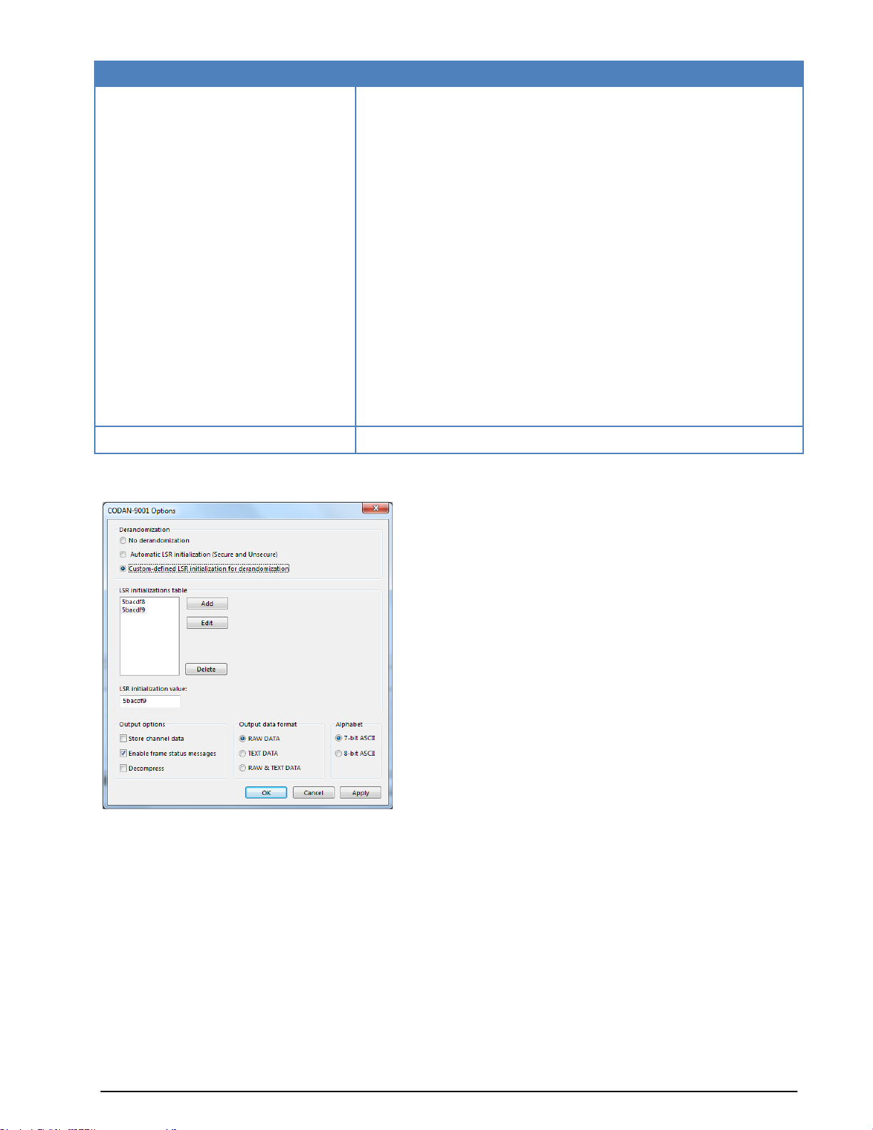
Parameter
Value
Supported functions
Output of demodulated multichannel symbols
Derandomization of secure-mode
Derandomization of unsecure-mode
Arbitrary start values for derandomization of secure-modes
Output of recognized start value in secure-mode
Output of status information
Output of recognized frame type
Decoding of chat-messages into text
Decoding of text-file transmissions into readable output
Decoding of data- transmissions into hexadecimal output
Decompress data
Store Channel Data for analysis purposes
Automatic recognition of secure and unsecure modes
7-bit-ASCII Alphabet used by CODAN-9102-Software
Secure Interactive Packets
Please enquire
Chirp decoding
The picture below shows the CODAN-9001 Options dialog. The settings from the dialog are stored into
the Codan9001Options.xml file.
The CODAN-9001 data transmission system uses a variable randomization in secure- and secureinteractive mode. The randomization vector can change between successive transmissions. The randomization value is shown in the status pane. In the two status-lines at the top of the decoding window the
frame type (DATA, ACK, IDLE) and some information about the decompressor (if used) are presented.
Possible derandomization options:
No derandomization - no manipulation of the demodulated symbols; in this case it is not possi-
ble to recognize frame characteristics and decode into TEXT DATA. Because the decoder does not
recognize the frame length, with every synchronization the maximum frame length is used for
decoding.
Automatic LSR initialization (Secure and Unsecure) - handles both the secure and unsecure
transmission cases; an unsecure transmission is automatically recognized. In the secure case the
decoder calculates the start value.
82 Transmission Modes WAVECOM Monitoring System W-SPECTRA, W-SPEED Manual V1.1.0
Page 93

CH
Frame 1
Frame 2
Frame 2
...
Frame n
1
Chnl packet 01
Chnl packet 17
Chnl packet 33
....
...
Custom-defined LSR initialization for derandomization - expects a seven-digit hexadecimal
value for initialization (note that it is important to enter leading zeros). This option should be
used if the initialization value is known, or if it is not possible to calculate the value automatically
due to poor signal conditions.
The CODAN-9001 decoder has the following output options:
Store channel data. The channel data output is very useful for analysis purposes. In the channel
data output every channel packet is stored in a file.
(C:\Users\Public\Documents\WAVECOM\W61PC\Data-Output\CODAN9001[SN])
Enable frame status messages. It is possible to activate frame status messages, with the rele-
vant checkbox. The frame status messages are printed in the decoder output. They show [PREAMBLE FOUND] and [EXTENDED PREAMBLE FOUND].
Decompress. The user can control the decompressor and the channel data output. Please refer
the section Compressed Mode specifics for further information on Compressed Mode. The user can
set the decoder/decompressor into the initial state with the Mode-Resync button in the
WAVECOM Toolbar.
RAW DATA - the output consists of synchronized and demodulated multichannel symbols in hex-
adecimal representation. Every symbol consists of 32 bits (16 channels * 2 bits/channel).
TEXT DATA - the demodulator output is processed into readable text.
TEXT & RAW DATA - if possible the decoder decodes into readable text, otherwise it outputs the
demodulated multichannel symbols as RAW DATA.
7 or 8-bit-ASCII. CODAN-9001 can use a 7-bit or an 8-bit alphabet, the choice being made by
selecting the appropriate radio button. The 7-bit alphabet is often used in transmissions handled
by the CODAN-9102 software.
The data is presented in two ways: hexadecimal-form, and ASCII-form.
At the beginning of every line the user can find the following information about the channel data packet:
CRC OK or CRC NOK (not O.K.)
SEQ [Nr] (Sequence number, a counter from zero up to the length of the packet)
ARQ [Nr] (ARQ number used from the modems to request packets not received correctly)
At the end of a packet some statistical data is stored.
In secure mode the channel data packet output is adapted, as the secure interactive packets have a
slightly different structure.
The extended preamble gives an indication as to whether the transmission is a group or broadcast call.
The frame type, shown in the decoder status bar, indicates if the current package is ACK, IDLE or DATA. If
a data package with a known length is recognized, the decoder shows its length.
DECODING OF CODAN DATA MODEM SIGNALS
Introduction
This section intends to offer an overview of the issues related to the practical decoding of the CODAN data
modem protocol using WAVECOM decoders. It is important for the user to be aware of any constraints and
limitations inherent in the decoding process during non-cooperative interception of this mode, and so possible issues are explained below.
Protocol overview
The CODAN-9001 modem uses 16 DQPSK carriers for the transport of payload data. Each carrier is independently modulated with data.
Each individual channel carries a channel packet. All 16 concurrent channel packets constitute a frame and
a number of frames constitute a multi-frame.
CODAN-9001 modem frame structure:
WAVECOM Monitoring System W-SPECTRA, W-SPEED Manual V1.1.0 Transmission Modes 83
Page 94

CH
Frame 1
Frame 2
Frame 2
...
Frame n
2
Chnl packet 02
Chnl packet 18
Chnl packet 34
...
...
3
Chnl packet 03
Chnl packet 19
Chnl packet 35
...
...
...
...
...
...
...
...
16
Chnl packet 16
Chnl packet 32
Chnl packet 48
...
Chnl packet m
Multi-frame 1
Each payload data packet has a constant length and a sequence number. However, the numbering in the
figure above only serves as an example, and due to the use of ARQ-based retransmissions the numbering
may not be sequential.
For the purpose of this explanation payload data is considered to be unprocessed user data and channel
encoded user data.
Independent of the payload data field, the sequence number field has its own error detecting and correcting code. Payload data in each channel packet is protected by a cyclic redundancy code (CRC). This feature is included in order to allow the ARQ protocol to request retransmission of packets received in error.
A session consists of one or more multi-frames. Depending on the amount of data queued for transfer the
length of a multi-frame may vary. The receiving modem will extract the frames from the multi-frame determining the number of channel packets and checking whether payload data was received without errors.
If a channel packet was received in error a re-transmission is requested. It should be clear from this that a
multi-frame may consist of a mixture of new data and re-transmitted data. Re-transmitted data may appear on any channel and in any position within a multi-frame. Additionally the transmitting modem may
opt to send ALE-like parity bit packets in a separate frame and even on another channel within the same
multi-frame as the payload data packet to which it belongs. This is indicated by the two packets belonging
together carrying the same sequence number. This mechanism is predominantly seen when the link quality deteriorates and consequently the number of re-transmissions increases.
In the “Broadcast” and “Group” modes multi-frames with new data appear for every fourth multi-frame –
in between data and coding information is repeated in the remaining three multi-frames.
Compressed mode specifics
For point-to-point channels CODAN modems utilize a dictionary based compression method, which allows
compression to be independent of the statistical characteristics of the source data. The dictionaries are
dynamically built depending on the data previously transmitted. Each modem uses one dictionary for reception and another one for transmission in such a way that a transmission dictionary at one end of the
link corresponds to a reception dictionary at the opposite end of the link. The ARQ protocol ensures that
the dictionaries are updated and synchronized. If the dictionaries deviate decompression becomes impossible as the buffer contents cannot be reconstructed. It is thus clear that for non-cooperative interception
deviating dictionaries pose a major problem.
CODAN decoding at the practical level
When engaging in non-cooperative monitoring a number of issues arise:
All frames and the sequence counters contained in therein must be received without errors. Re-
transmitted packets must be discarded.
Missing packets or packets with a failed CRC must not be accepted; otherwise data output will be
incomplete.
In case of uncompressed transmissions packets with a failed CRC may be marked as such. In case of
compressed transmissions decompression consequently becomes impossible due to the deviating dictionaries built during the non-cooperative interception session. Only when a new link is set up, it is possible to
start over with empty dictionaries. It is important to understand that in case of compressed transmissions
exclusively the data from one party may be forwarded to the de-compressor. This understanding is especially important if during non-cooperative interception both parties in a “Chat Session” are received as
forwarding the data from both parties will immediately poison the dictionary.
HF transmission issues
The CODAN ARQ protocol is adapted to the propagation conditions in the HF range, but obviously relies on
an active link between the two communicating parties. This link does not exist in the case of non-
84 Transmission Modes WAVECOM Monitoring System W-SPECTRA, W-SPEED Manual V1.1.0
Page 95

Parameter
Value
Frequency range
HF
Operation modes
Asynchronous simplex
Modulation
MFSK-13
Speed
50.0 or 75.0 ms
Receiver settings
DATA, CW, LSB or USB
Input format(s)
AF, IF
Additional Info
ITA-2
cooperative monitoring and thus complete and correct data output is fully dependent on error-free reception – there is no way to ask for re-transmission.
As transmissions do not contain source or destination addresses the monitor in case of single-frequency
half-duplex traffic must manually select the party to monitor. This may be achieved by adjusting the receiver squelch, adjusting the receiver HF gain or the use of directional antennas to suppress the unwanted
signal.
Real-time monitoring issues
To capture the contents of a CODAN modem data transmission the monitoring equipment should be placed
as close as possible to the transmitter site of the interesting party. This is the only way to ensure that the
quality of the signal is sufficient to secure that all transmitted packets are correctly captured.
To facilitate the decoding of data the WAVECOM decoder in addition to outputting the decoded data in the
decoder window also saves raw channel data with sequence numbers and including bad packets to a text
file. The text file may be processed manually or by a user provided application.
COQUELET-13
COQUELET-13 is an asynchronous system and uses a start and idle tone of 1052 Hz. As with COQUELET-8,
the first group contains 8 tones for keying, and the second group 4 tones.
COQUELET-13 has a tone duration of 75 ms which is equivalent to a 50 Bd Baudot transmission, with 1.5
stop bits. Two code tables are defined for this mode, Code Table 0 and Code Table 1.
WAVECOM Monitoring System W-SPECTRA, W-SPEED Manual V1.1.0 Transmission Modes 85
Page 96

Tone Number
Frequency Hz
Bit 1
Bit 2
Bit 3
Bit 4
Bit 5
First tone Group
1 812 1 1 1 2
842 1 1 3
872 1 4
902 1 5
932 1 1 6
962 1 1
7
992 1
8
1022
9 1052
Idle or start tone
Second Tone Group
10
1082
1 1
11
1112
1
12
1142
1
13
1172
Parameter
Value
Frequency range
HF
Operation modes
Simplex
Modulation
MFSK-8
Speed
37.5, 50.0 or 75.0 ms
Receiver settings
DATA, CW, LSB or USB
Input format(s)
AF, IF
Additional Info
ITA-2
Tone Assignment of COQUELET-13:
COQUELET-8
COQUELET-8 is an MFSK (Multiple Frequency Shift Keying) system, and like the PICCOLO system translates an ITA-2 character into a sequence of two tones.
The first group of tones contains 8 tones (1 - 8) and the second group the tones 5 - 8. Tones 1 - 4 of the
second group are not defined.
Coquelet-8 is a synchronous system with a tone duration of 75.0 ms, 50.0 ms or 37.5 ms. One ITA-2
character is transmitted in 75 or 150 ms, which is equivalent to 50 or 100 Bd Baudot with 1.5 stop bits
(codeword length 7.5 Bit).
An IDLE sequence is sent when no traffic is at hand. Transmissions start with a synchronization preamble,
and end with several EOT characters.
86 Transmission Modes WAVECOM Monitoring System W-SPECTRA, W-SPEED Manual V1.1.0
Page 97

Tone Number
Frequency Hz
Bit 1
Bit 2
Bit 3
Bit 4
Bit 5
First tone Group
1 773 1 1 1 2
800 1 1 3
826 1 4
853 1 5
880 1 1 6
907 1 1
7
933 1
8
960 Second Tone Group
5 880 1 1 6
907 1 7
933 1 8
960
Parameter
Value
Frequency range
HF
Operation modes
Simplex FEC
Modulation
MFSK-8
Speed
37.5, 50.0 or 75.0 ms
Receiver settings
DATA, CW, LSB or USB
Input format(s)
AF, IF
Additional Info
ITA-2
Tone Assignment of COQUELET-8:
COQUELET-80
COQUELET-80 is a synchronous MFSK system with error correction (FEC). Various references note two different systems: COQUELET-80S and COQUELET-82S. COQUELET-82S can be used in both side bands and
uses extended handshaking and synchronizing sequences (extended protocol).
COQUELET-80 is used with the ATU-80 (Arabic) or the ITA-2 (Latin) alphabet. As for COQUELET-8 a character is coded with two tone assignments from group 1 and group 2.
Error correction is done by transmitting every character twice with a specified time offset. The second
transmitted character is mathematically reformatted (MOD 8). The leading (DX) and trailing characters
(RX) always have the same ODD or EVEN parity.
At the beginning of a message the RX character positions are filled with IDLE sequences. This mode does
error recognition, but no error correction.
WAVECOM Monitoring System W-SPECTRA, W-SPEED Manual V1.1.0 Transmission Modes 87
Page 98

Tone Number
Frequency Hz
Bit 1
Bit 2
Bit 3
Bit 4
Bit 5
First Tone Group
1 773 1 1 1 2
800 1 1 3
826 1 4
853 1 5
880 1 1 6
907 1 1
7
933 1
8
960 Second Tone Group
5 880 1 1 6
907 1 7
933 1 8
960
Parameter
Value
Frequency range
VHF/UHF
Operation modes
Analogue Selcal
Modulation
FM, SUB Tone
Receiver settings
FM, BW = 12 kHz
Input format(s)
AF, IF
Tone no.
Freq. Hz
Tone no.
Freq. Hz
Tone no.
Freq. Hz
1
60.0
19
118.8
37
183.5
2
67.0
20
120.0
38
186.2
3
69.3
21
123.0
39
189.9
4
71.9
22
127.3
40
192.8
5
74.4
23
131.8
41
196.6
6
77.0
24
136.5
42
199.5
7
79.7
25
141.3
43
203.5
8
82.5
26
146.2
44
206.5
9
85.4
27
151.4
45
210.7
Tone Assignment of COQUELET-80:
CTCSS
The CTCSS selective calling system is defined according to EIA standard RS-220 and operates in the subaudio range. Applying this Continuous Tone Controlled Squelch System stations may be selectively called
either as a single user or as a group.
Tone Allocation
88 Transmission Modes WAVECOM Monitoring System W-SPECTRA, W-SPEED Manual V1.1.0
Page 99

Parameter
Value
Frequency range
HF
Operation modes
Asynchronous
Modulation
FSK
Symbol rate
50,75, 100 or 150 Bd, variable 30-650 Bd
Center frequency
2000 Hz
Shift/Bandwidth
850 Hz
Receiver settings
DATA, CW, LSB or USB
Input format(s)
AF, IF
Additional Info
Async FSK only
Parameter
Value
Frequency range
HF
Operation modes
Simplex/Duplex ARQ, Broadcast
Modulation
CARRIER KEYING
Speed
0 - 90 WPM
Receiver settings
DATA, CW, LSB or USB
Input format(s)
AF, IF
10
88.5
28
156.7
46
218.1
11
91.5
29
159.8
47
225.7
12
94.8
30
162.2
48
229.1
13
97.4
31
165.5
49
233.6
14
100.0
32
167.9
50
241.8
15
103.5
33
171.3
51
250.3
16
107.2
34
173.8
52
254.1
17
110.9
35
177.3
18
114.8
36
179.9
A CTCSS controlled receiver only switches on, in case a carrier modulated with the pre-programmed
CTCSS tone is received. For this system 52 tones are defined:
CV-786
CV-786 is an asynchronous FSK system and is based on ASCII. No error detection or error correction is
implemented.
For CV-786 mode standard baud rates from 50 to 150 Baud are available. Non-standard baud rates may
be selected using the Baudrate menu item.
From Options | Alphabet… you can select from different ITA-2 and ITA5 aphabets.
CW-MORSE
The Auto function will automatically detect Morse keying speeds within the range 0 - 90 WPM (words per
minute). The keying speed is continuously updated and displayed.
WAVECOM Monitoring System W-SPECTRA, W-SPEED Manual V1.1.0 Transmission Modes 89
Page 100

Parameter
Value
Frequency range
VHF
Operation modes
Digital Selcal
Modulation
FSK
Symbol rate
133.7,134.4, 137 Bd
Receiver settings
FM, BW = 15kHz
Input format(s)
IF
Normal
Inverse
Normal
Inverse
Normal
Inverse
Normal
Inverse
023
047
155
731
325
526
516
432
025
244
156
265
331
465
523
246
026
464
162
503
332
455
526
325
031
627
165
251
343
532
532
343
032
051
172
036
346
612
546
132
036
172
174
074
351
243
565
703
043
445
205
263
356
212
606
631
047
023
212
356
364
131
612
346
051
032
223
134
365
125
624
632
053
452
225
122
371
734
627
031
054
413
226
411
411
226
631
606
065
271
243
351
412
143
632
624
071
306
244
025
413
054
654
743
072
245
245
072
423
315
662
466
The center frequency can be set to any value between 200 and 3400 Hz via the Center item in the De-
modulator menu. The center frequency is nominally 800 Hz which is dictated by the quartz filters of professional receivers while other receivers work with 1000 Hz.
The shift can be set between 100-300 Hz and controls the lock-in-range of the center frequency (bandwidth = 1.2 x shift).
Using Options | Alphabet the output can be set to Latin, Cyrillic, Greek, Arabic or Hebrew.
Using Options | AFC the continuous automatic tuning to the center frequency of the CW-Morse signal can
be enabled or disabled.
The software reports an error condition (ERROR) if the controlled parameters as the dot-dash ratio, the inter-word or inter-character breaks deviate too much from the standard, and error-free decoding cannot be
maintained.
DCS SELCAL
DCS stands for Digital Coded Squelch (also known as DCSS, Digitally Coded Squelch Signaling), and is
used for selective calls and remote control applications.
The data is transmitted on sub audible tones within the frequency range 2 Hz to 300 Hz. In practice, DCS
is similar to CTCSS, but uses 104 octal 3-digit code words instead of continuous analogue tones.
The data is sent as a series of 23-bit GOLAY encoded frames without any sync bits. Polarity can be normal
or inverse, and must be selected by the user.
DCS Code Table
90 Transmission Modes WAVECOM Monitoring System W-SPECTRA, W-SPEED Manual V1.1.0
 Loading...