

Page 1
WMO2 G900 / G1800 / G1900
Version:
Date:
Reference:
GSM MODEM
1.0
Friday 21 May 1999
WCOM/GSM/WMO2/WMO2ATDOC
39 rue du Gouverneur Général Eboué
92130 Issy les Moulineaux
Tél: 01 46 29 08 00
Fax: 01 46 29 08 08
www.wavecom.com
Page 2

WMO2 G900 / G1800 / G1900
WCOM/GSM/WMO2/WMO2ATDOC Friday 21 May 1999
Document amendments
Issue Date Status Author Comments
1.1 21-05-99
P
C. Guillemin
N. Higelin
O. Capron
F. Desnoues
D. Martinez
Creation
WAVECOM confidential © ii
Page 3

WMO2 G900 / G1800 / G1900
WCOM/GSM/WMO2/WMO2ATDOC Friday 21 May 1999
Contents
1 Introduction............................................................................1
1.1 Document scope ........................................................................... 1
1.2 Related documents........................................................................ 1
1.3 Definitions..................................................................................... 2
1.4 Acronyms and abbreviations......................................................... 2
2 Technical Data........................................................................3
2.1 Basic offer ..................................................................................... 3
2.1.1 Contents....................................................................................... 3
2.1.2 Packaging..................................................................................... 3
2.1.3 User manual ................................................................................. 3
2.2 Accessories ................................................................................... 3
2.2.1 Cordons........................................................................................ 3
2.2.2 Headset........................................................................................ 4
2.2.3 Antenna ....................................................................................... 4
2.2.4 Power supply................................................................................ 4
2.3 Options ......................................................................................... 4
2.3.1 Car Kit .......................................................................................... 4
2.4 Product references......................................................................... 4
2.4.1 Ordering references....................................................................... 4
2.4.2 Markings and Labels..................................................................... 4
2.5 Physical characteristics ................................................................. 6
2.5.1 Shape........................................................................................... 6
2.5.2 Mechanical philosophy.................................................................. 7
2.6 Conditions of use........................................................................... 8
2.6.1 Climatic and mechanical environment............................................ 8
2.6.2 Electrical environment................................................................... 9
2.7 Electrical characteristics .............................................................. 10
2.8 Connectors.................................................................................. 11
2.8.1 Connector location...................................................................... 11
2.8.2 Connectors description................................................................ 11
2.9 Capabilities.................................................................................. 13
2.10 Accessories description............................................................. 13
2.10.1 Headset...................................................................................... 13
2.10.2 Serial link.................................................................................... 13
2.10.3 Serial and audio link.................................................................... 14
2.10.4 Remote Modem Control Link ....................................................... 15
2.10.5 Power supply cordon .................................................................. 15
2.10.6 Cables pinning............................................................................ 16
3 AT Commands interface........................................................17
3.1 Command syntax ........................................................................ 17
3.1.1 Request syntax........................................................................... 18
3.1.2 Answer syntax............................................................................ 19
3.2 Default settings........................................................................... 20
WAVECOM confidential © iii
Page 4

WMO2 G900 / G1800 / G1900
WCOM/GSM/WMO2/WMO2ATDOC Friday 21 May 1999
3.3 Global behaviour ......................................................................... 21
3.3.1 SIM Insertion, SIM Removal ........................................................ 21
3.3.2 Background initialisation ............................................................. 22
4 Commands set......................................................................23
4.1 General commands ..................................................................... 23
4.1.1 Manufacturer identification +CGMI.............................................. 23
4.1.2 Request model identification +CGMM.......................................... 23
4.1.3 Request revision identification +CGMR ........................................ 23
4.1.4 Product Serial Number +CGSN.................................................... 24
4.1.5 Select TE character set +CSCS .................................................... 24
4.1.6 Request IMSI +CIMI.................................................................... 24
4.1.7 Card Identification +CCID........................................................... 25
4.1.8 Capabilities list +GCAP................................................................ 25
4.1.9 Repeat last command A/ ............................................................. 25
4.1.10 Power off +CPOF........................................................................ 25
4.1.11 Set phone functionality +CFUN.................................................... 26
4.1.12 Phone activity status +CPAS ....................................................... 27
4.1.13 Report Mobile Equipement errors +CMEE .................................... 27
4.1.14 Extended error report +CEER....................................................... 27
4.2 Call Control commands ............................................................... 28
4.2.1 Dial command D......................................................................... 28
4.2.2 Hang-Up command H ................................................................. 29
4.2.3 Answer a call A........................................................................... 30
4.2.4 Remote disconnection................................................................. 30
4.2.5 DTMF signals +VTD, +VTS ......................................................... 30
4.2.6 Redial last number ATDL............................................................. 30
4.2.7 Automatic answer ATS0 ............................................................. 31
4.2.8 Incoming Call Bearer +CICB......................................................... 31
4.2.9 Gain control +VGR, +VGT............................................................ 32
4.2.10 Microphone Mute Control +CMUT.............................................. 32
4.2.11 Speaker & Microphone selection +SPEAKER ................................ 33
4.2.12 Echo Cancelation +ECHO ............................................................ 34
4.2.13 SideTone modification +SIDET .................................................... 34
4.3 Network service related commands............................................. 35
4.3.1 Signal Quality +CSQ ................................................................... 35
4.3.2 Operator selection +COPS........................................................... 36
4.3.3 Network registration +CREG........................................................ 37
4.3.4 Read operator name +WOPN....................................................... 37
4.3.5 Preferred operator list +CPOL ...................................................... 38
4.4 Security commands..................................................................... 39
4.4.1 Enter PIN +CPIN ........................................................................ 39
4.4.2 Enter PIN2 +CPIN2...................................................................... 41
4.4.3 PIN remaining attempt number +CPINC...................................... 41
4.4.4 Facility lock +CLCK...................................................................... 42
4.4.5 Change password +CPWD.......................................................... 43
4.5 Phonebook commands................................................................ 44
4.5.1 Select phonebook memory storage +CPBS................................... 44
4.5.2 Read phonebook entries +CPBR .................................................. 44
4.5.3 Find phonebook entries +CPBF.................................................... 44
4.5.4 Write phonebook entry +CPBW ................................................... 45
4.5.5 Phonebook phone search +CPBP................................................. 46
4.5.6 Move action in phonebook +CPBN............................................... 47
4.5.7 Subscriber number +CNUM ........................................................ 48
4.5.8 Avoid phonebook init +WAIP....................................................... 48
4.6 Short Message Service commands.............................................. 49
4.6.1 Parameters definition .................................................................. 49
4.6.2 Select message service +CSMS................................................... 50
4.6.3 Preferred Message Storage +CPMS............................................. 50
4.6.4 Preferred Message Format +CMGF.............................................. 51
4.6.5 Save Settings +CSAS.................................................................. 51
WAVECOM confidential © iv
Page 5

WMO2 G900 / G1800 / G1900
WCOM/GSM/WMO2/WMO2ATDOC Friday 21 May 1999
4.6.6 Restore settings +CRES............................................................... 51
4.6.7 Show text mode parameters +CSDH ........................................... 52
4.6.8 New message indication +CNMI.................................................. 52
4.6.9 Read message +CMGR ............................................................... 53
4.6.10 List message +CMGL.................................................................. 54
4.6.11 Send message +CMGS ............................................................... 55
4.6.12 Write Message to Memory +CMGW............................................ 56
4.6.13 Send Message From Storage +CMSS .......................................... 57
4.6.14 Set Text Mode Parameters +CSMP.............................................. 58
4.6.15 Delete message +CMGD ............................................................. 58
4.6.16 Service center address +CSCA..................................................... 59
4.6.17 Select Cell Broadcast Message Types +CSCB............................... 59
4.6.18 Cell Broadcast Message Identifiers +WCBM................................. 59
4.7 Supplementary Services commands............................................ 60
4.7.1 Call forwarding +CCFC................................................................ 60
4.7.2 Call barring +CLCK...................................................................... 61
4.7.3 Modify SS password +CPWD...................................................... 61
4.7.4 Call waiting +CCWA ................................................................... 62
4.7.5 Calling line identification restriction +CLIR ................................... 63
4.7.6 Calling line identification presentation +CLIP................................ 63
4.7.7 Connected line identification presentation +COLP........................ 64
4.7.8 Advice of charge +CAOC............................................................. 65
4.7.9 Accumulated call meter +CACM.................................................. 65
4.7.10 Accumulated call meter maximum +CAMM................................. 66
4.7.11 Price per unit and currency table +CPUC...................................... 66
4.8 Data commands.......................................................................... 67
4.8.1 Bearer type selection +CBST ....................................................... 67
4.8.2 Service reporting control +CR...................................................... 67
4.8.3 Cellular result codes +CRC .......................................................... 68
4.8.4 Radio link protocol parameters +CRLP ......................................... 68
4.9 V24-V25 commands.................................................................... 69
4.9.1 Fixed DTE rate +IPR.................................................................... 69
4.9.2 DTE-DCE character framing +ICF................................................. 70
4.9.3 DTE-DCE local flow control +IFC.................................................. 71
4.9.4 Set DCD signal &C...................................................................... 71
4.9.5 Set DTR signal &D...................................................................... 71
4.9.6 Set DSR signal &S ...................................................................... 72
4.9.7 Back to online mode O ................................................................ 72
4.9.8 Result code suppression Q.......................................................... 72
4.9.9 DCE response format V ............................................................... 72
4.9.10 Default configuration Z................................................................ 72
4.9.11 Save configuration &W ............................................................... 72
4.9.12 Auto-tests &T............................................................................. 73
4.10 Specific AT commands ............................................................. 73
4.10.1 Cell environment description +CCED........................................... 73
4.10.2 Automatic RxLev indication +CCED ............................................. 74
4.10.3 General Indications +WIND ......................................................... 75
4.10.4 Data ciphering mode between ME and MSC +ALEA.................... 75
4.10.5 Data ciphering mode +CRYPT..................................................... 76
4.10.6 Key management +EXPKEY ......................................................... 76
4.10.7 Informations on PLMN +CPLMN.................................................. 76
4.10.8 Analog digital converters measurements +ADC........................... 76
4.10.9 Mobile Equipment event reporting +CMER................................... 76
4.10.10 Read Language Preference +WLPR.............................................. 77
4.10.11 Write Language Preference +WLPW ............................................ 77
4.10.12 Read GPIO value +WIOR ............................................................. 77
4.10.13 Write GPIO value +WIOW............................................................ 77
4.11 Other AT commands................................................................. 77
4.11.1 V.25 ter recommandation............................................................ 77
4.11.2 GSM 07.05 recommandation....................................................... 77
4.11.3 GSM 07.07 recommandation....................................................... 77
4.12 Fax Management commands.................................................... 78
WAVECOM confidential © v
Page 6

WMO2 G900 / G1800 / G1900
WCOM/GSM/WMO2/WMO2ATDOC Friday 21 May 1999
4.12.1 Setting up the module for fax ...................................................... 78
4.12.2 Setting up the PC fax application:................................................ 78
4.12.3 Restoring the module's default profile for data call........................ 78
5 Miscellaneous.......................................................................79
5.1 Disclaimer ................................................................................... 79
5.2 Trademarks ................................................................................. 79
5.3 Copyright .................................................................................... 79
6 Appendices...........................................................................80
6.1 ME error result code: +CME ERROR: <error>.............................. 80
6.2 Message service failure result code: +CMS ERROR: <er> ........... 80
6.3 Specific error result codes ........................................................... 81
6.4 IE Cause values from GSM 04.08 recommendation..................... 82
6.5 GSM 04.11 Annex E-2: Mobile originating SM-transfer.............. 84
6.6 Unsolicited result codes............................................................... 85
6.7 Final result codes ........................................................................ 85
6.8 Intermediate result codes ............................................................ 86
6.9 Operator names........................................................................... 87
WAVECOM confidential © vi
Page 7

WMO2 G900 / G1800 / G1900
WCOM/GSM/WMO2/WMO2ATDOC Friday 21 May 1999
1 Introduction
This document is intended for every person being brought to work with the
modem WISMO WMO2 G900, G1800 or G1900.
1.1 Document scope
This document presents the technical characteristics of the connections,
interfaces and power supply of the modem WISMO WMO2 in the G900,
G1800 and G1900 terminal version.
This document describes the AT commands allowing the user to issue
communications in the voice, data or fax mode with the modem WISMO
WMO2 G900, G1800 and G1900 and for SMS's reception and expedition.
1.2 Related documents
This interface document is based on the following recommendations and
reference documents:
[1] ETS 300 019 Environmental conditions and environmental tests
for telecommunications equipment.
[2] SAE J1113 Transients Voltage Suppression in Automotive
Vehicle.
[3] WAVE Internal Qualification Plan version 1.1.
[4] ETSI GSM 07.05 European digital cellular telecommunication
system (phase 2); Use of DTE-DCE interface for
Short message service and cell broadcast service
[5] ETSI GSM 07.07 European digital cellular telecommunication
system (phase 2); AT command set for GSM
Mobile Equipment
[6] ITU-T V.25 ter. Serial asynchronous automatic dialling and control
[7] ETSI GSM 03.40 European digital cellular telecommunication
system (phase 2); Technical realisation of the
Short Message Service (SMS) Point-to-Point (PP)
[8] ETSI GSM 03.38 European digital cellular telecommunication
system (phase 2); Alphabets and language-
specific information
[9] WMO2sp14 Technical characteristics of the WMO2 modem
line.
[10] SII015 v7.9 AT-Commands interface layer specification for the
phase 2 software of the WMO2 modem line.
WAVECOM confidential © 1
Page 8

WMO2 G900 / G1800 / G1900
WCOM/GSM/WMO2/WMO2ATDOC Friday 21 May 1999
1.3 Definitions
For the purposes of the AT-commands interface description in this
document, the following definitions apply:
Command mode: In Command mode, the modem is not
communicating with a remote station, and is ready
to accept commands. When powering-up, the
modem automatically enters this mode, and
automatically returns to this mode when a call is
disconnected.
Online mode: Also called data mode: In Online mode, the modem
is communicating with a remote station. Data
coming through the RS232 serial link are treated as
data and transmitted to the called part, and data
received from the called part are transmitted to the
terminal through the RS232 serial link. Online mode
is activated by successful completion of a command,
either manually or automatically, to originate or
answer a call, or by receiving the ATO command to
return to online mode from Command mode.
[...]: Items enclosed in square brackets are optional.
The square brackets themselves must not appear in
the command line.
<...>: Some syntactical elements are mentioned enclosed
in angle brackets. Actually the meaning (values) for
those elements must appear in the command and
the angle brackets are omitted.
All other characters, including " " ", "&", "?", "==", parentheses, etc., shall
appear in commands as written.
1.4 Acronyms and abbreviations
For the purposes of the AT-commands interface description in this
document, the following abbreviations apply:
WAVECOM confidential © 2
Page 9

WMO2 G900 / G1800 / G1900
WCOM/GSM/WMO2/WMO2ATDOC Friday 21 May 1999
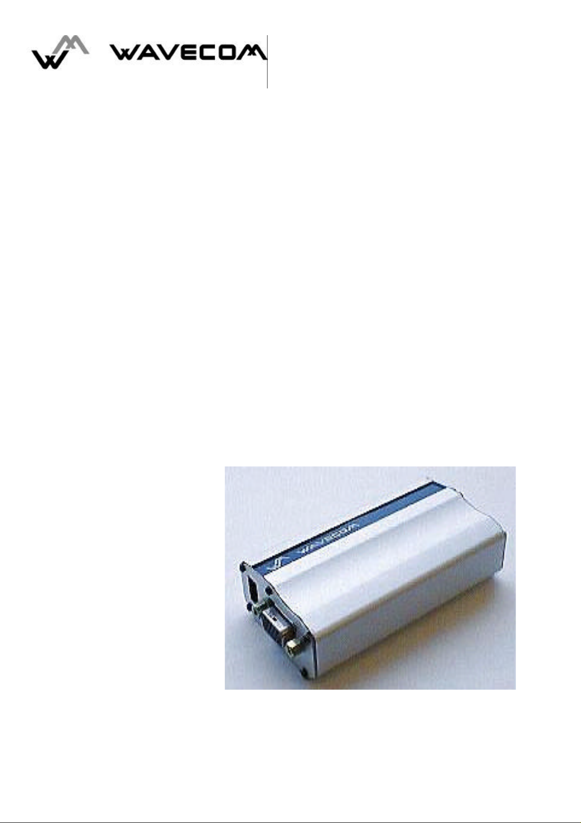
2 Technical Data
This section deals with the specifications of the second generation of
Wavecom's GSM modem. Under the generic reference WMO2-GXXXX are 3
different modems grouped: WMO2-G900 for GSM standard, WMO2-G1800
for DCS standard and WMO2-G1900 for PCS standard.
All these modems are based on WISMO concept, it means each modem
includes a WISMO1B-Gxxxx module.
In this section you will find, on the one hand the description of the basic
modem offer and, on the other hand several accessories description.
2.1 Basic offer
2.1.1 Contents
The basic offer comprises the following elements:
• Modem
• Mechanical fixation (holding bridle)
• Power supply cable + fuse
• User manual
2.1.2 Packaging
The Basic offer set is presented in a unique conditioning, Which external
dimensions are close to the following values:
70mm (width) x 60mm (height) x135mm (length).
This is a cardboard box. It is build-in small waves, which are covered with
a thin film of white ice-cold paper.
2.1.3 User manual
The user manual is realised in a size closed to the following values:
105mm (width) x 148,5 mm (height) (that is 1/2 A5).
It contains twenty-two pages except the cover page.
2.2 Accessories
2.2.1 Cordons
Two cordons could be proposed:
• serial link and audio cable (Y cordon) for a low power audio solution (for
example: headset, phone receiver, ...),
• serial link and audio cable (Y cordon) for Car Kit option that is with a
higher power on the audio part.
WAVECOM confidential © 3
Page 10

WMO2 G900 / G1800 / G1900
WCOM/GSM/WMO2/WMO2ATDOC Friday 21 May 1999
2.2.2 Headset
The headset allows audio hands free function. This feature implements a
weak power speakerphone and a microphone.
TBD: standard products
2.2.3 Antenna
Two solutions could be proposed:
• a standard deported cellular phone antenna,
• a WAVECOM designed short antenna.
2.2.4 Power supply
An AC/DC converter (220V~ / 12V-2A) enables a direct powering on the
power network.
2.3 Options
2.3.1 Car Kit
Thanks to an audio power amplifier, a microphone - that can be fixed on a
vehicle's sun visor - and a loud speaker - that can be fixed on the vehicle
dashboard -, one can obtain a hands free embedded solution.
Speaker (8Ω) and directional microphone are supplied with this option.
2.4 Product references
2.4.1 Ordering references
The WMO2 modem product line references are set up using the
WMO2-GXXXX base.
The references respect the following syntax:
• WMO2-G900 for the GSM 900 standard;
• WMO2-G1800 for the DCS 1800 standard;
• WMO2-G1900 for the PCS 1900 standard.
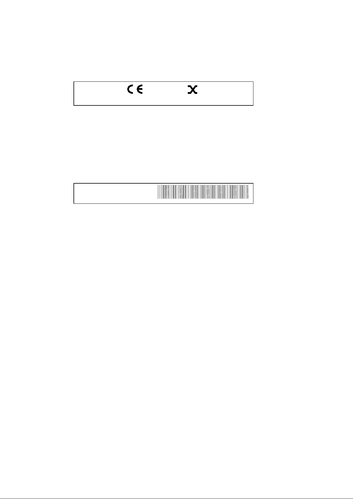
2.4.2 Markings and Labels
2.4.2.12.4.2.1 Product labelProduct label
This label is built with anodise aluminium. It has a blue silk screen
treatment (marking: aluminium colour) and is fitted on the upper convex
mechanical side. It supports the WAVECOM logo.
Dimension: 96x10 mm.
WAVECOM confidential © 4
Page 11
WMO2 G900 / G1800 / G1900
REF PROD: WMO2-GXXX
IMEI
01650165
Made by Wavecom
WCOM/GSM/WMO2/WMO2ATDOC Friday 21 May 1999
2.4.2.22.4.2.2 Production stickerProduction sticker
This label is located on the bottom side of the product and contains CE
marking (in order to improve the productivity on assembly line, this marking
will be printed or silk screen treated in advance).
Dimension: 60x9.5 mm.
2.4.2.32.4.2.3 CE and IMEI stickerCE and IMEI sticker
This label is placed on the bottom of the product, it contains the following
legible information
REF PROD: (WMO2-GXXX)
P/N (WMXXXXX)
and IMEI number in barre code.
This last one includes the product serial number.
Dimensions: 60 x 9.5 mm.
P/N: WMxxxxx
2.4.2.42.4.2.4 Label packagingLabel packaging
This label is put on the product box and defines the contents.
WAVECOM confidential © 5
Page 12
WMO2 G900 / G1800 / G1900
WCOM/GSM/WMO2/WMO2ATDOC Friday 21 May 1999
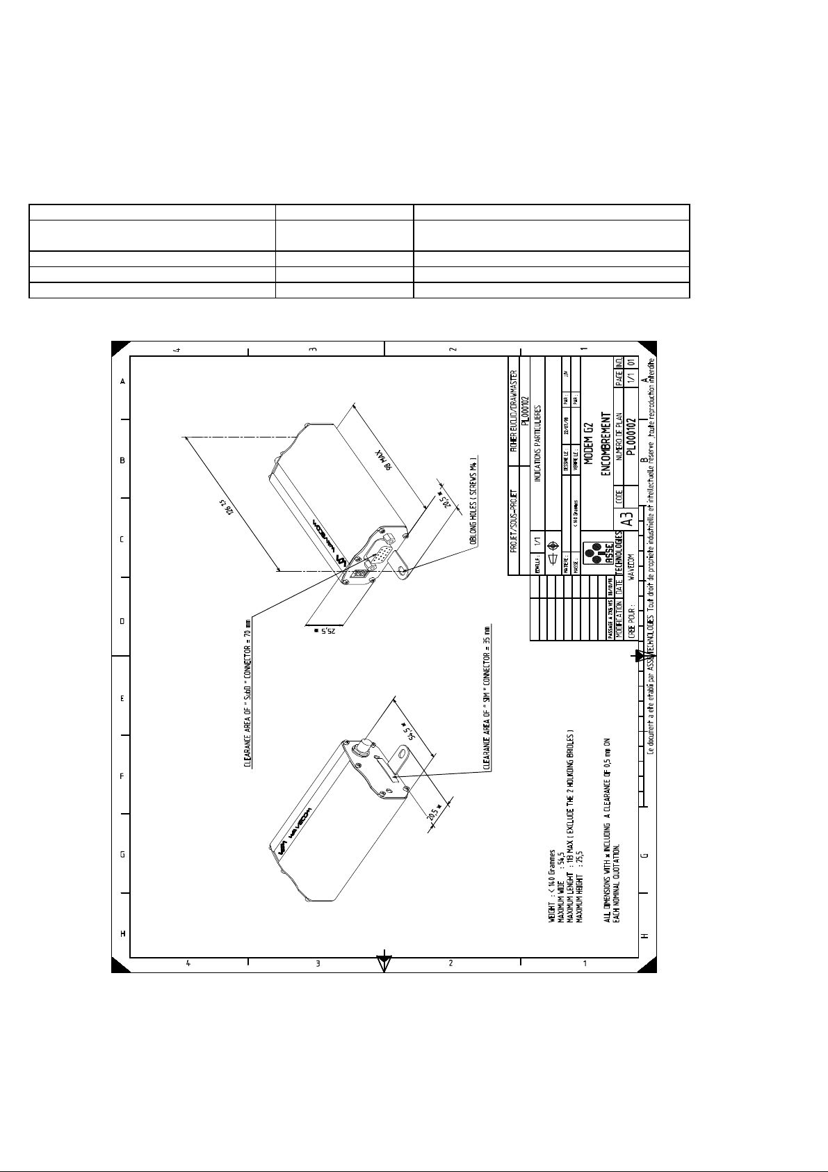
2.5 Physical characteristics
2.5.1 Shape
The physical shape is given as follow:
Physical characteristic Qualification Comments
Dimension
Absolute maximum dimension
Weight < 140 g
Volume 13.23 cm3
Case Aluminium profile
98x54x25 mm
110x54x25 mm
Without the connectors quotations.
WAVECOM confidential © 6
Page 13
WMO2 G900 / G1800 / G1900
WCOM/GSM/WMO2/WMO2ATDOC Friday 21 May 1999
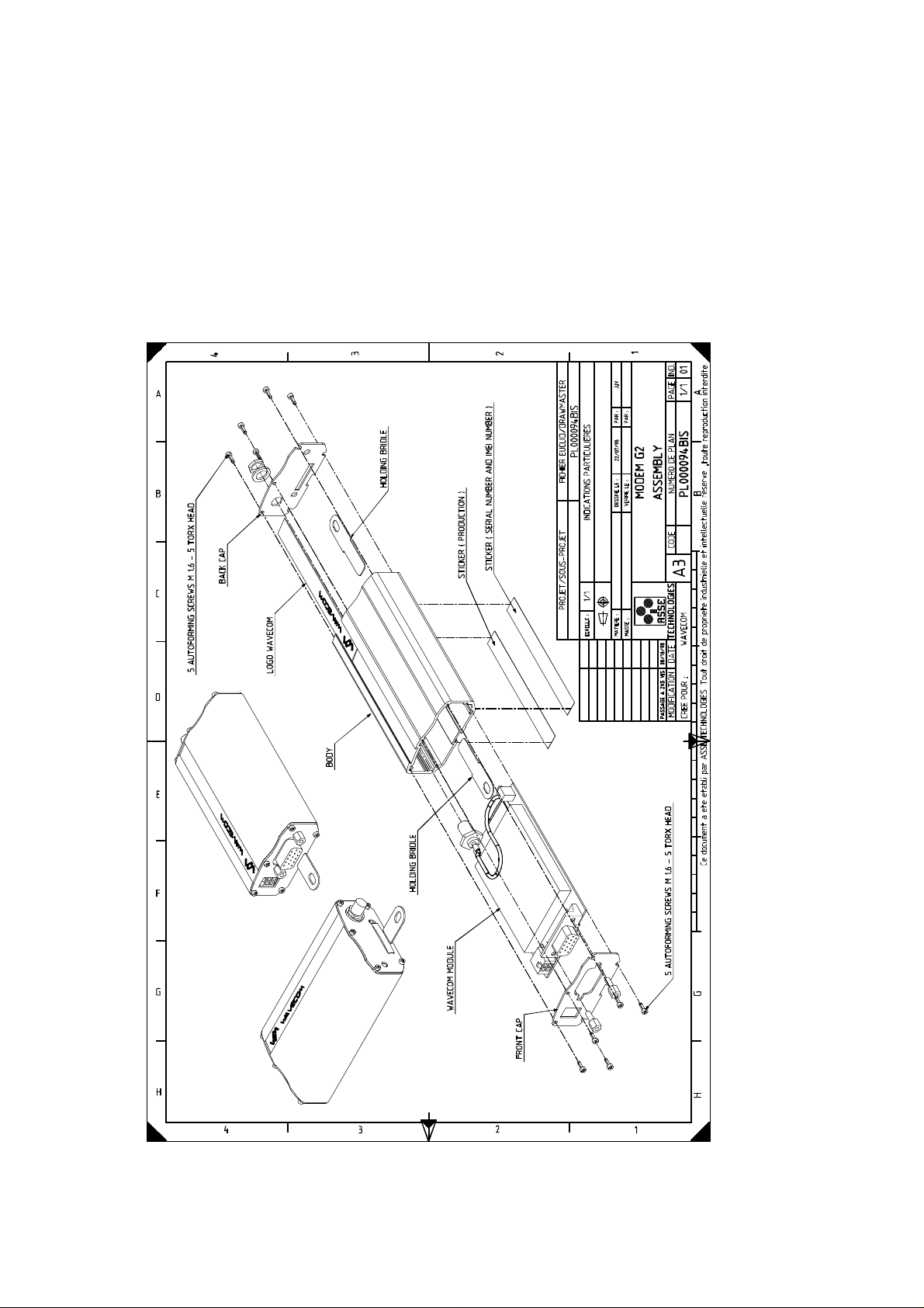
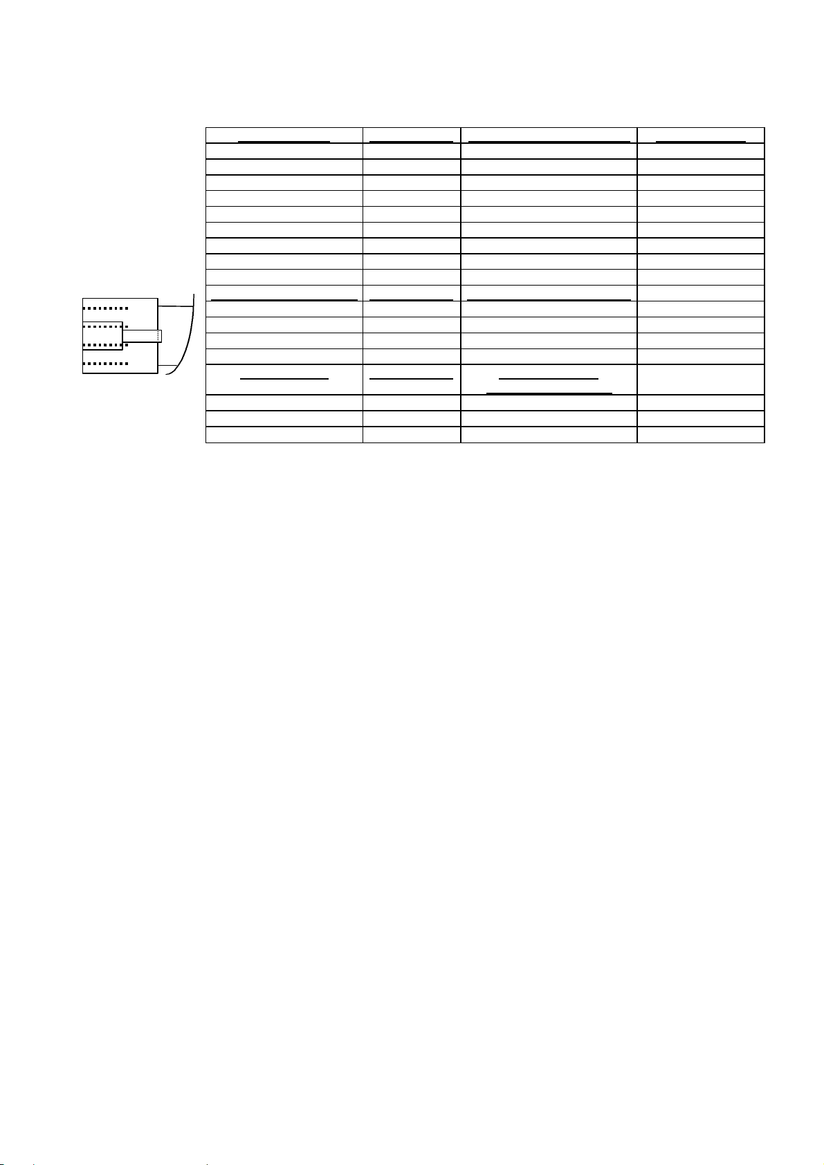
2.5.2 Mechanical philosophy
The mechanical casing of the WMO2 modem line is built from an
aluminium profile ended by two stoppers at each edge.
All input/output interfaces are realised through three connectors
placed at the two extremities of the profile. No cordon is fixed to the
casing.
The SIM card (micro-SIM) is put on an extractable drawer.
A red LED indicates the functioning mode of the product.
WAVECOM confidential © 7
Page 14

WMO2 G900 / G1800 / G1900
WMO2_Gxxxx
ENVIRONNEMENTAL CLASSES
90% - 100% RH
90% - 100% RH
90% - 100% RH
WCOM/GSM/WMO2/WMO2ATDOC Friday 21 May 1999
2.6 Conditions of use
2.6.1 Climatic and mechanical environment
The following figure shows environment standard constraints:
TYPE OF TEST STANDARDS STORAGE TRANSPORTATION OPERATING (PORT USE)
Class 1.2 Class 2.3 Class 7.3
Cold IEC 68-2.1 -25° C 72 h -40° C 72 h -20° C 16 h
Ab test
Dry heat IEC 68-2.2 +70° C 72 h +70° C 72 h +55° C 16 h
Bb test
Change of temperature IEC 68-2.14 -40° / +30° C 5 cycles -20° / +30° C 3 cycles
Na/Nb test t1 = 3 h t1 = 3 h
Damp heat IEC 68-2.30 +30° C 2 cycles +40° C 2 cycles +40° C 2 cycles
cyclic Db test
variant 1 variant 1 variant 1
Damp heat IEC 68-2.56 +30° C 4 days +40° C 4 days +40° C 4 days
Cb test
Sinusoidal vibration IEC 68-2.6 5 - 62 Hz : 5 mm / s
Fc test 62 - 200Hz : 2 m / s2
3 x 5 sweep cycles
5 - 20 Hz : 0.96 m2 / s3 10 -12 Hz : 0.96 m2 / s3
Random vibration IEC 68-3.36 20 - 500Hz : - 3 dB / oct 12 - 150Hz : - 3 dB / oct
wide band Fdb test 3 x 10 min 3 x 30 min
WAVECOM confidential © 8
Page 15

WMO2 G900 / G1800 / G1900
WCOM/GSM/WMO2/WMO2ATDOC Friday 21 May 1999
2.6.2 Electrical environment
The following table sums up electrical constraints in an automotive
environment:
Length of transient Cause
Steady state Failed Voltage Regulator oo
3 - 5 minutes Jump start with 24 V
battery
200ms to 400ms
< 0.32 s Inductive Load
< 0.20 s Alternator Field Decay <1 J
90ms Ignition Pulse, Battery
1ms
Load dump - i.e.,
disconnection of battery
while at high charging
rates
Switching Transient
Disconnected
Mutual Coupling in
Harness (Note)
Energy
capability
Voltage
Amplitude
+ 18 V
oo
+/- 24 V
≥10 J
≤125V
<1 J
-300V to +80V
-100V to -40V
<0.5 J
≤75V
<1 J
<200V
Possible
frequency of
application
Infrequent
Infrequent
Infrequent
Often
Each Turn-Off
<500Hz Several
Times in vehicle
Life
Often
15µs Ignition Pulse, Normal <0.001 J
<3V
Accessory Noise <1.5V 50 Hz to 10 kHz
Transceiver Feedback 20mV R.F.
Note: These transients may be present on any wire in the vehicle.
<500Hz
Continuous
WAVECOM confidential © 9
Page 16

WMO2 G900 / G1800 / G1900
WCOM/GSM/WMO2/WMO2ATDOC Friday 21 May 1999
2.7 Electrical characteristics
The following table summarises the electrical characteristics defined for the
different input/output connections.
Parameters MIN TYP MAX UNIT Comments
Power supply:
Input supply voltage
Input supply voltage with Car Kit option
Input peak supply current @5V*/ 6V
**
Input average supply current @5V*/ 6V** in
communication mode
Input average supply current @5V*/ 6V
in idle mode (paging period 480ms)
Input average supply current @5V* in idle
mode with auto-shutdown function
***
Serial link:
RS232 standard
Audio (head set):
microphone input current @2V/2KΩ
absolute microphone input voltage
speaker output current 150Ω //1nF
absolute speaker impedance
**
5*/6**13,5
13,5
0,5
16
32
18
2,5*/ 0,9
450*/200
35
10
100
32
**
**
V
V
A
mA
mA
mA
mA
mVpp
mA
Ω
GSM or DCS/PCS
GSM or DCS/PCS
GSM or DCS/PCS
SIM 3 5 V
*
only GSM devices.
**
only DCS and PCS devices.
***
auto shutdown function could be activate if the serial link leads a
non hardware flow-control (CTS/RTS non used). This hardware
feature will not be available with the first products.
WAVECOM confidential © 10
Page 17
WMO2 G900 / G1800 / G1900
WCOM/GSM/WMO2/WMO2ATDOC Friday 21 May 1999
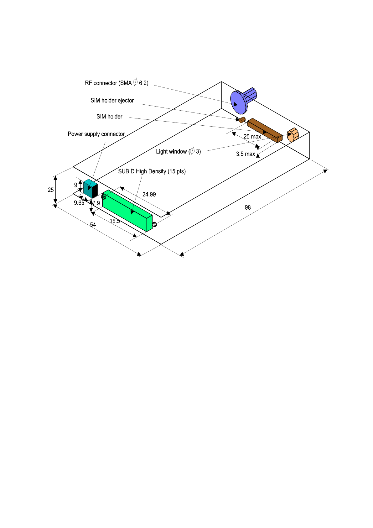
2.8 Connectors
2.8.1 Connector location
2.8.2 Connectors description
We considered the following constraints in the connector choice:
• Size;
• Mechanical characteristics;
• Electrical performances;
• Industrialisation (surface assembly choice).
In order to extract or insert the Micro SIM card, it is strongly
recommended to press with a sharp element (a pen for example) the SIM
holder ejector.
If this procedure is no respected, the SIM holder could be destroyed.
WAVECOM confidential © 11
Page 18
WMO2 G900 / G1800 / G1900
123456789
11111
1
432
1
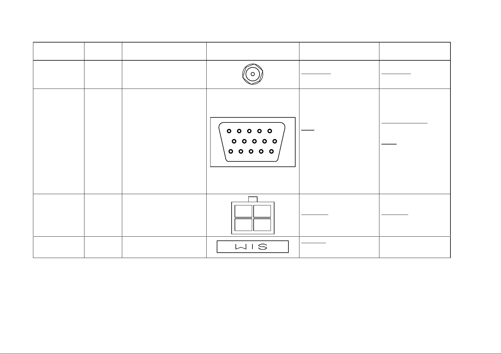
WCOM/GSM/WMO2/WMO2ATDOC Friday 21 May 1999
Function
Type Pining Drawing Ref. supplier Mating connector
connector
RF connector SMA RADIALL:
R284310085
1 DCD (CT109)
2 TX (CT103)
6 RX (CT104)
Serial link
7 DSR (CT107)
8 DTR (CT108/2)
AUDIO link
SUB D
High
Density
(15 pt.)
9 GND
11 CTS (CT106)
12 RTS (CT105)
13 RI (CT125)
4 MICROPHONE (+)
5 MICROPHONE (-)
JST:
KSEY-15S-3B6L18-13
10 SPEAKER (+)
15 SPEAKER (-)
BOOT
RESET
Power Supply
connector
Micro-Fit
(4pts)
3 BOOT
14 RESET
1 V+BATTERY
2 GROUND
3-4 AUXI
MOLEX:
43045-0409
examples
RADIALL:
R125073
ITT CANNON:
ZDEA-15P-SB
or
JST:
KEC-15P
with contact JKSP2143
MOLEX:
43025-0400
SIM holder MOLEX:
MICRO SIM
52828-0611
WAVECOM confidential © 12
Page 19

WMO2 G900 / G1800 / G1900
SUB-D High Density
SUB-D 9 points
Shielded cable 9 wires + braid of shield:
Cable length: 1,5 m
WCOM/GSM/WMO2/WMO2ATDOC Friday 21 May 1999
2.9 Capabilities
Functions of the WMO2 modem line are defined as follow:
GSM DCS/PCS
Standard
Interface Serial interface RS232 V.24/V.28
SMS Mobile Originated (MO) and Mobile
Data Asynchronous 2400, 4800, 9600 baud
Fax 2400/4800/7200/9600 baud, GSM
Audio FR and EFR operation
900 MHz.
Class 4 (2W).
GSM phase 2.
AT command set based on V.25ter and
GSM 07.05 & 07.07.
Auto-bauding function between baud
rates 2400 and 19200
No auto-framing available
Terminated (MT). Text & PDU Mode
point to point. Cell broad cast.
In accordance with GSM 07.05
rates.
Transparent and Non Transparent mode
In Non Transparent Mode: 300, 1200,
1200/75 baud.
Mode 3.1 kHz (PSTN) and V110 (ISDN)
teleservice 62 in Transparent Mode.
Class 1.
Group 3 compatible.
1: Head Set
2: Car Kit (in option)
1800 MHz or 1900 MHz
Class 1 (1W)
GSM phase 2.
Serial interface RS232 V.24/V.28
AT command set based on V.25ter and
GSM 07.05 & 07.07.
Auto-bauding function between baud rates
2400 and 19200
No auto-framing available
Mobile Originated (MO) and Mobile
Terminated (MT). Text & PDU Mode point
to point. Cell broad cast.
In accordance with GSM 07.05
Asynchronous 2400, 4800, 9600 baud
rates.
Transparent and Non Transparent mode
In Non Transparent Mode: 300, 1200,
1200/75 baud.
Mode 3.1 kHz (PSTN) and V110 (ISDN)
2400/4800/7200/9600 baud, GSM
teleservice 62 in Transparent Mode.
Class 1.
Group 3 compatible.
FR and EFR operation
1: Head Set
2: Car Kit (in option)
2.10 Accessories description
2.10.1 Headset
To be defined.
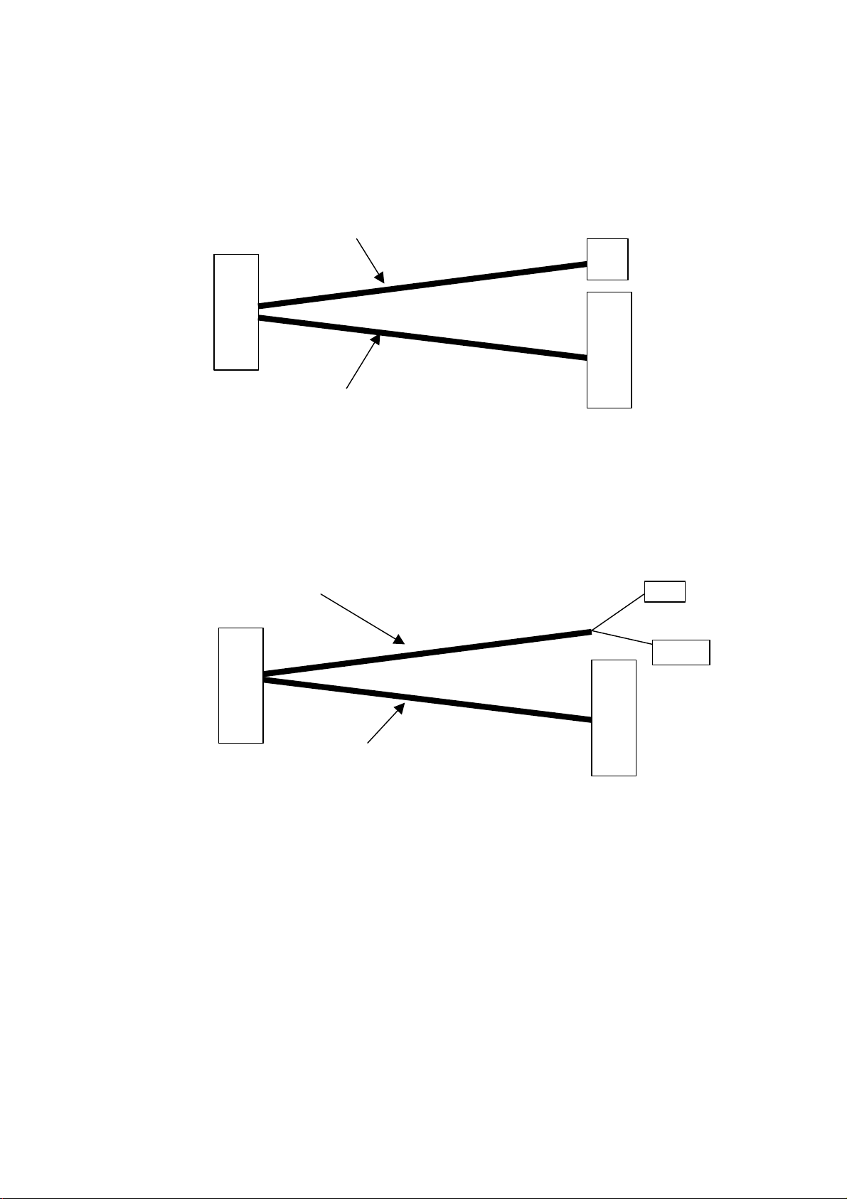
2.10.2 Serial link
15 points male +
braid of shield
soldered on SUB D
Wire constitution: tinned copper 7x0.2 mm
Wire constitution: 7x 0.15 (26AWG)
Operating temperature range: -20°C/+85°C.
WAVECOM confidential © 13
female
+ braid of shield
soldered on SUB D
body + cover.
Page 20
WMO2 G900 / G1800 / G1900
SUB-D High Density
SUB-D 9 points
Modular Jack
Shielded cable 9 wires + braid of shield:
Flat cable 4 wires:
Cable length: 1,5 m
Jack audio mono 2,5 mm
Shielded cable 9 wires + braid of shield:
Cable2x2 wires:
Cable length: 1,5 m
Female RCA connector
SUB-D High Density 15
body + cover
WCOM/GSM/WMO2/WMO2ATDOC Friday 21 May 1999
2.10.3 Serial and audio link
2.10.3.12.10.3.1 Low power audioLow power audio
Wire constitution: tinned copper 7x0.15 mm (26AWG)
Operating temperature range: -20°C/+85°C
4P/4C
15 points male +
braid of shield
soldered on SUB D
Wire constitution: tinned copper 7x0.2 mm
Wire constitution: 7x 0.15 (26AWG)
Operating temperature range: -20°C/+85°C.
female
+ braid of shield
soldered on SUB D
body + cover.
2.10.3.22.10.3.2 High power audioHigh power audio
2 Wires constitution (speaker): tinned copper 7x0.2 mm (24AWG)
1 conductor with shield (microphone)
Operating temperature range: -20°C/+85°C
pts male + braid of
shield soldered on SUB
D body + cover
female (microphone)
(speaker)
SUB-D 9 pts female
+ braid of shield
soldered on SUB D
Wire constitution: tinned copper 7x0.2 mm
Wire constitution: 7x0.15 (26AWG)
Operating temperature range: -20°C/+85°C
WAVECOM confidential © 14
Page 21
WMO2 G900 / G1800 / G1900
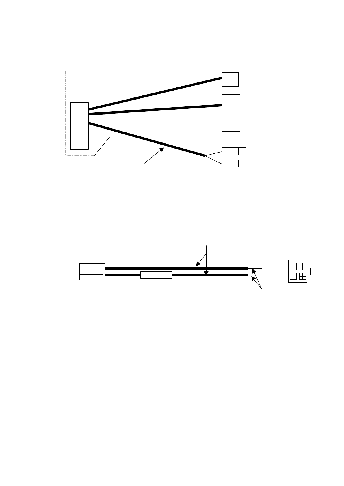
Cable length: 1,5 m
Low power
Cable length: 10 cm
Flat cable 4 wires:
MICRO FIT connector 4 pts (MOLEX: 43025-0400)
Contacts (x2) (MOLEX: 43030-0007)
Side view
Fuse 5x20 mm. (2,5 A)
Red
Cable: 1 wire.
Tinned wires
Cable length: 1 m
WCOM/GSM/WMO2/WMO2ATDOC Friday 21 May 1999
2.10.4 Remote Modem Control Link
Also called "Service cable".
audio cable
as defined
above
2 push buttons or
micro switches
Wire constitution: tinned copper 7x0.15 mm (26AWG)
2.10.5 Power supply cordon
Ame: tinned copper 24x0.2 mm
Section: 0.75 mm²
Operating temperature range: -20°C/+85°C
Black
WAVECOM confidential © 15
Page 22
WMO2 G900 / G1800 / G1900
Top view
1
3
WCOM/GSM/WMO2/WMO2ATDOC Friday 21 May 1999
2.10.6 Cables pinning
Assembly example
SUB-D 9CTSSUB-D 9CTS ConnectionConnection SUB D 15CTS (RS232)SUB D 15CTS (RS232) Signal nameSignal name
1 (White)1 (White)
2 (Grey)2 (Grey)
3 (Purple)3 (Purple)
4 (Blue)4 (Blue)
5 (Black)5 (Black)
6 (Orange)6 (Orange)
7 (Yellow)7 (Yellow)
8 (Brown)8 (Brown)
9 (Green)9 (Green)
Modular Jack 4P/4CModular Jack 4P/4C ConnectionConnection SUB D 15CTS (AUDIO)SUB D 15CTS (AUDIO)
1 (Yellow/White)1 (Yellow/White)
2 (Red/White)2 (Red/White)
3 (Green/White)3 (Green/White)
4 (Black/White)4 (Black/White)
Flying wiresFlying wires ConnectionConnection SUB D 15CTSSUB D 15CTS
(Pink)(Pink)
(Blue/White)(Blue/White)
(Black)(Black)
ÜÜ
ÜÜ
ÜÜ
ÜÜ
ÜÜ
ÜÜ
ÜÜ
ÜÜ
ÜÜ
ÜÜ
ÜÜ
ÜÜ
ÜÜ
ÜÜ
ÜÜ
ÜÜ
1 (White)1 (White) DCD (CT109)DCD (CT109)
6 (Grey)6 (Grey) RX (CT104)RX (CT104)
2 (Purple)2 (Purple) TX (CT103)TX (CT103)
8 (Blue)8 (Blue) DTR (CT108/2)DTR (CT108/2)
9 (Black)9 (Black) GNDGND
7 (Orange)7 (Orange) DSR (CT107)DSR (CT107)
12 (Yellow)12 (Yellow) RTS (CT105)RTS (CT105)
11 (Brown)11 (Brown) CTS (CT106)CTS (CT106)
13 (Green)13 (Green) RI (CT125)RI (CT125)
4 (Yellow/White)4 (Yellow/White) microphone(+)microphone(+)
10 (Red/ White)10 (Red/ White) speaker(+)speaker(+)
15 (Green/White)15 (Green/White) speaker(-)speaker(-)
5 (Black/White)5 (Black/White) microphone(-)microphone(-)
(Boot/Reset/GND)(Boot/Reset/GND)
3 (Pink)3 (Pink) BOOTBOOT
14 (Blue/White)14 (Blue/White) RESETRESET
9 (Black)9 (Black) GNDGND
WAVECOM confidential © 16
Page 23

WMO2 G900 / G1800 / G1900
WCOM/GSM/WMO2/WMO2ATDOC Friday 21 May 1999
3 AT Commands interface
This chapter describes the interface based on the Hayes protocol
standard between the TE and the ME. The AT commands presented
here in are intended to manage voice, data and fax communication
as well as SMS sending and receiving.
3.1 Command syntax
There are 3 types of commands:
1. Set command:
using the = (equal) character, it is possible to assign a value
to a parameter.
2. Read command:
using the ? (question mark) character, it is possible to read the
current setting of a parameter.
3. Test command:
using the character sequence =? (equal followed by question
mark), it is possible to test if a parameter is supported by the
modem and to read the supported values for that parameter.
Examples:
AT+CPIN=#### ' to enter the PIN code of the SIM.
ATS0? ' to determine the number of ring indicators
awaited before automatically answering.
AT+COPS=? ' to determine which PLMN are currently
available.
The following only applies in command mode.
All available commands for the WMO2 modem line are presented in
the chapter 4.
WAVECOM confidential © 17
Page 24

WMO2 G900 / G1800 / G1900
WCOM/GSM/WMO2/WMO2ATDOC Friday 21 May 1999
3.1.1 Request syntax
3.1.1.13.1.1.1 Basic syntaxBasic syntax
At fixed baud rate uppercase or lowercase letters can be used to
type in the AT-Commands. But the use of both upper and lowercase characters in the same command is not permitted.
The end character, except in some cases for which it is indicated, is
always the <CR> (Carriage Return) character.
The syntax is based on the nominal Hayes standard:
• Each command begins with a 2 letters prefix "AT" (ATtention)
except the "+++" and the "A/" commands;
• The command's body is a single character or an
& (ampersand) character immediately followed by a single
character;
• A + (plus) character may immediately follow the AT prefix to
indicate it is an extended command format in that case, a
letter (chosen among the following one: A, C, D, E, F, G, I, M,
S, T, V or W) immediately follows the + character, then comes
the command itself (the body);
• The parameters (if any) of the command are placed at the end.
Examples:
ATA ' to answer a call.
AT&W ' to store the profile in memory.
ATQ1 ' to suppress the extended syntax result codes.
ATS0=2 ' to automatically answer a call after 2 rings.
It is possible to concatenate several commands on the same
command line, example: ATQ1S0=2;&W
You must insert a ; (semicolon) straight after each command that
use a = (equal) or ? (question mark) character and after each
extended format command.
There is no need of any special character for all other commands
(i.e. there are no ; (semicolon) between the Q1 and S0=2
commands above, but there is one straight after the S0=2
command before the &W command.
3.1.1.23.1.1.2 Special casesSpecial cases
If the serial link exchange baud rate is not fixed, case of the modem
working in autobauding mode, it is not possible to type in the
commands using lowercase characters.
When sending SMS messages, the end character is no longer the
<CR> (carriage return), it is the <CTRL>Z character (Escape
character).
WAVECOM confidential © 18
Page 25

WMO2 G900 / G1800 / G1900
WCOM/GSM/WMO2/WMO2ATDOC Friday 21 May 1999
3.1.2 Answer syntax
There are 2 types of answers: information text and result codes.
The answer of a command may be build of both an information text
and a result code.
The answer may be transmitted in numeric form or alphabetic
(verbose) form depending upon the setting of the V parameter.
The response, either in numeric form or in alphabetic form, consists
of a header, a body and a trailer.
The header and the trailer are the same, there are build with 2
characters <CR> <LF> (Carriage return and Line Feed).
This applies for all commands except the V0 and the Q1
commands.
When the command syntax is wrong, the modem responds ERROR.
When the command syntax is correct but with incomplete or
incorrect parameters, the modem responds +CME ERROR: <Err> or
+CMS ERROR: <CMSErr> with the corresponding error code (<Err>
respectively <CMSErr>).
If the command syntax is correct and all parameters are valid but
the network refuses the command whatever the reason, the modem
responds +CMS ERROR: <CMSErr>, where <CMSErr> is the
reason (if any) given by the network.
The modem responds OK when the network accepted the
command and both the syntax and the parameters where correct.
For some commands such as "AT+CPIN?" or "AT+EXPKEY?" or
"ATQ1", the modem will not give the OK string at the end of the
command execution.
Moreover there are 3 sub-types of answers. These sub-types
describe answers that are return at different states of the modem.
Final result type : indicates the full completion of an AT
command and can be considered as a
willingness to accept new commands
from the TE. Example: "OK" or "ERROR".
Intermediate result type : is a report of the execution progress of
the currently being treated AT
command. Example
"CONNECT <speed>".
Unsolicited result type : indicates the happening of an event
not directly ensuing from a previous AT
command. Example "RING".
WAVECOM confidential © 19
Page 26

WMO2 G900 / G1800 / G1900
WCOM/GSM/WMO2/WMO2ATDOC Friday 21 May 1999
3.2 Default settings
The following table shows the different storable parameters, the
command to store them and there default value.
CommandCommand AT&WAT&W (E2P) (E2P) AT+CSASAT+CSAS
(SIM, E2P)(SIM, E2P)
+CMEE X 0
+CSCS <char. set> "PCCP437"
ATS0 <# of Ring> 0 (no auto-answer)
+CICB X 2 (speech)
+VGR <n> 2 (all speakers)
+VGT <n> 2 (all microphones)
+SPEAKER X 0 (Speaker 0 & Micro 0)
+ECHO All 160, 12, 5, 512, 10
+SIDET X 1,1
+CREG <mode>,<form> 0
+CLCK X No SIM or Network lock
+CPWD <pwd> 00000000 (SIM & Net lock)
+WAIP <mode> 0
+CMGF <mode> 1 (text)
+CSDH X 0
+CNMI All 0, 0, 0
+CSMP All 1, 67, 0, 0
+CSCA <sca> SIM dependant (phase 2)
+CCWA <n> 0
+CLIR <n> 0
+CLIP <n> 0
+COLP <n> 0
+CBST All 0, 0, 1
+CRLP All 61, 61, 48, 6
+CR <mode> 0
+CRC <mode> 0
+IPR X 0 (autobaud)
+IFC X 2,2
+ICF X 3,4
E X 0
&C X 1
&D X 1
Q X 0
V X 1
&S X 1
Default valueDefault value
The default setting of the RS232 serial link handler shown above in
the table corresponds to the following setting:
Baud rate : Autobauding (admitting rates from 2400 to
19200 bps)
Data length : 8 bits
Parity : None
Stop bit : 1
Flow control : Hardware (RTS/CTS)
To tune this settings please use the commands +IPR, +IFC and
+ICF.
WAVECOM confidential © 20
Page 27

WMO2 G900 / G1800 / G1900
WCOM/GSM/WMO2/WMO2ATDOC Friday 21 May 1999
3.3 Global behaviour
3.3.1 SIM Insertion, SIM Removal
SIM card Insertion and Removal procedures are supported. These
are software functions based on the reading of the hardware SIM
presence pin. This pin state (open/closed) is continuously watched.
When the SIM presence pin indicates a presence of "somewhat" in
the SIM connector, the module tries to establish a SIM logical
session. Depending if the "somewhat" is a SIM Card or not, the SIM
logical session will be successfully established or not.
The AT+CPIN? command delivers the following answers:
• If the SIM presence pin indicates "nothing", the answer to
AT+CPIN? is "+CME ERROR: 10" (SIM not inserted).
• If the SIM presence pin indicates "something" and the
inserted Card is a valid SIM Card, the answer to AT+CPIN?
is "+CPIN: xxx" depending of the SIM PIN state.
• If the SIM presence pin indicates "something" and the
inserted Card is not a valid SIM Card, the answer to
AT+CPIN? is "CME ERROR: 10".
• These both last status are not immediately available after
powering-up due to the background initialisation. During
this step and before the SIM presence pin indicates
"somewhat", the AT+CPIN? command returns
"+CME ERROR: 515" (Please wait, initialisation in progress).
When the SIM presence pin indicates "nothing" and the previously
inserted SIM Card was removed, an IMSI detach procedure is
executed, and all the user data corresponding to this previous SIM
are removed from the memory (Phonebooks, SMS etc.).
The modem can then still emit calls but only in the emergency
mode (only emergency numbers can be dialled).
WAVECOM confidential © 21
Page 28

WMO2 G900 / G1800 / G1900
WCOM/GSM/WMO2/WMO2ATDOC Friday 21 May 1999
3.3.2 Background initialisation
After a valid PIN entry, many SIM user data information are loaded
in the modem memory (Phonebooks, SMS status…). This operation
can last a long time when reading huge phonebooks.
The AT+CPIN? command answers just after verification of the PIN.
User Data are loaded in background after the PIN checking.
This means, that some data of the SIM may not be available
straight after the "OK" (if PIN is valid) of the PIN Entry function was
received by the TE. Data that may be affected are particularly the
phonebook's entries.
So that any access to phonebooks features will then be refused by
the following error message "+CME ERROR: 515" or
"+CMS ERROR: 515" meaning "please wait, service is not available,
initialisation in progress".
Also this kind of answer may be returned by the modem in several
circumstances:
• when trying to execute another AT command before the
previous one was executed to the end.
• when swapping from (or to) ADN to (or from) FDN and
trying to immediately read the concerned phonebook;
• when giving the +CPIN? command (SIM Status) just after a
SIM insertion and before the modem could execute a valid
SIM Card logical session.
WAVECOM confidential © 22
Page 29
WMO2 G900 / G1800 / G1900
WCOM/GSM/WMO2/WMO2ATDOC Friday 21 May 1999
4 Commands set
For convenience the <CR> and <CR><LF> sequences are not
indicated in the examples shown in the following description.
4.1 General commands
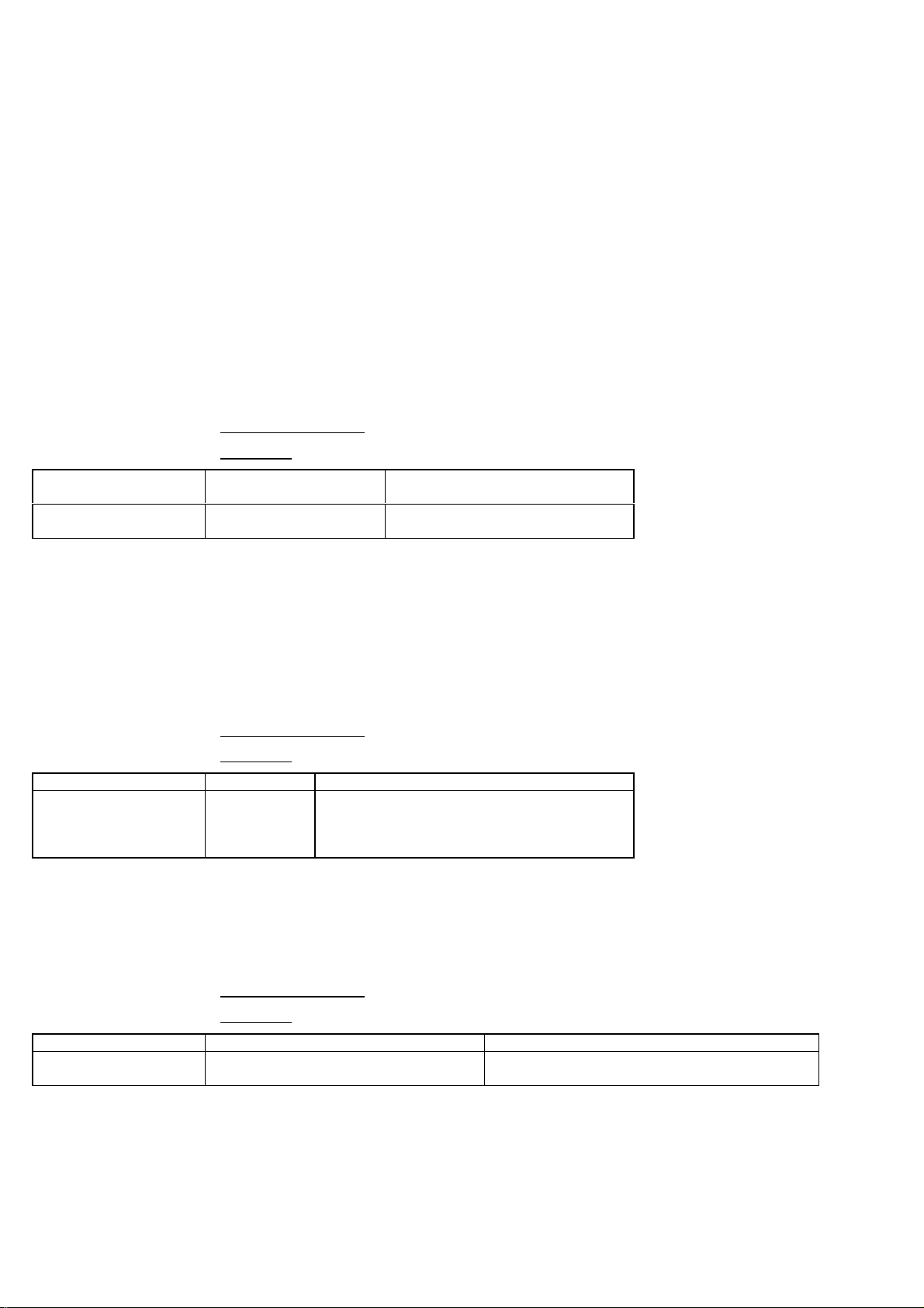
4.1.1 Manufacturer identification +CGMI
This command gives the manufacturer identification.
It is only a read command.
There is no possibility to set a value or to test the parameters.
Command Syntax: AT+CGMI
Example:
Application to GSM AT+CGMI Get manufacturer
identification
GSM to application WAVECOM MODEMOKCommand valid, Wavecom
modem
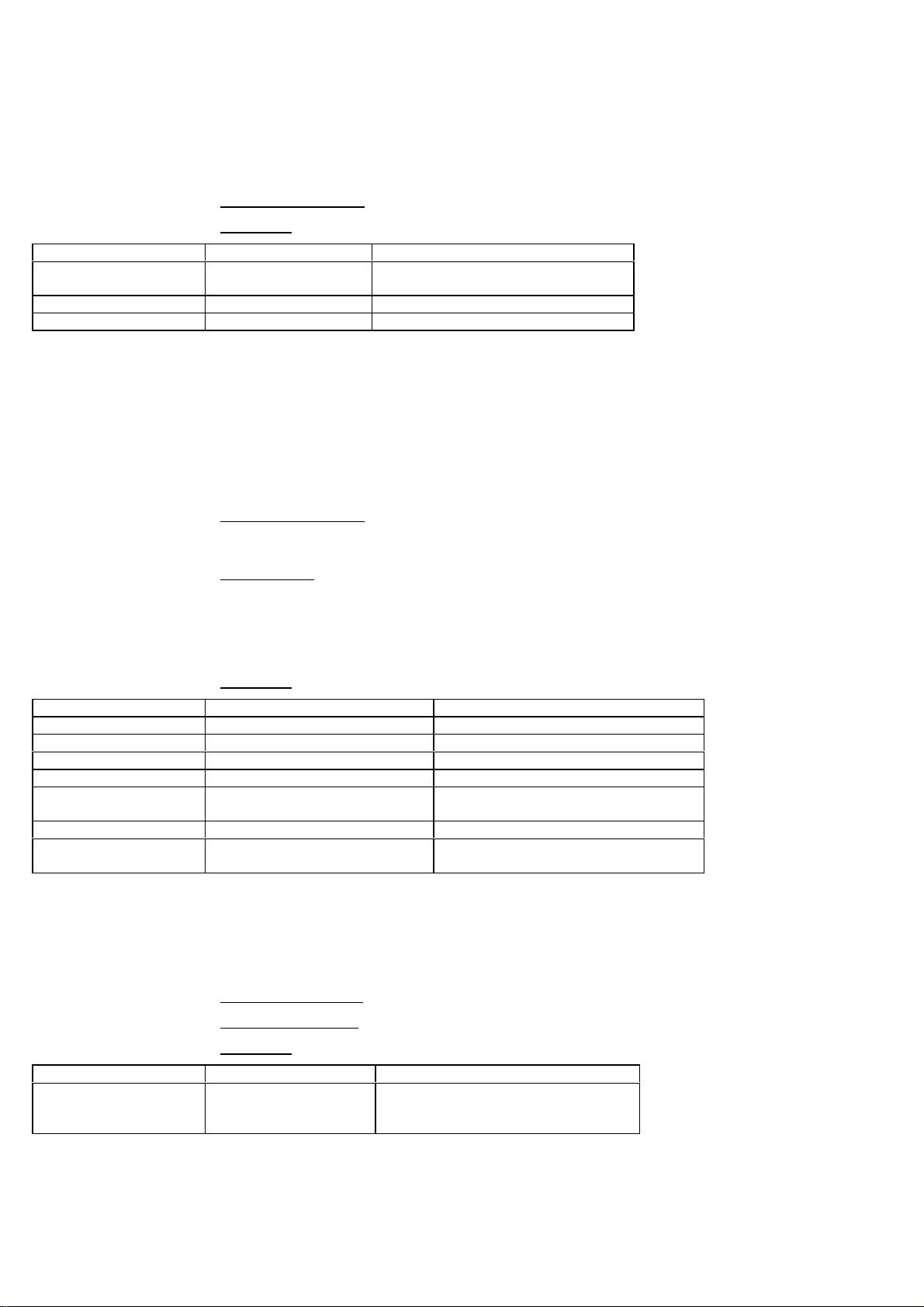
4.1.2 Request model identification +CGMM
This command is used to get the supported bands (GSM 900, DCS 1800,
PCS 1900).
The answer could be a combination of different bands in the case of
multiband modem.
It is only a read command.
There is no possibility to set a value or to test the parameters.
Command Syntax: AT+CGMM
Example:
Application to GSM AT+CGMM Get hardware version
GSM to application 900P
OK
GSM 900 MHz primary band, or
"900E" (extended band),
"1800" (DCS), "1900" (PCS) or
"MULTIBAND"
4.1.3 Request revision identification +CGMR
This command is used to read the software version.
It is only a read command.
There is no possibility to set a value or to test the parameters.
Command Syntax: AT+CGMR
Example:
Application to GSM AT+CGMR get software version
GSM to application 300_D250 641680 012099 18:10OKSoftware release 3.00 generated on the
20st of January 1999
WAVECOM confidential © 23
Page 30
WMO2 G900 / G1800 / G1900
WCOM/GSM/WMO2/WMO2ATDOC Friday 21 May 1999
4.1.4 Product Serial Number +CGSN
This command allows the user application to know the IMEI of the modem.
It is only a read command.
There is no possibility to set a value or to test the parameters.
Command Syntax: AT+CGSN
Example:
Application to GSM AT+CGSN Request IMEI
GSM to application 135790248939
IMEI present in E2PROM
OK
Application to GSM AT+CGSN Request IMEI
GSM to application +CME ERROR: 22 IMEI not found in E2PROM
4.1.5 Select TE character set +CSCS
This commands informs the ME which character set is used by the TE.
The ME is then able to convert each character of entered or displayed
string.
This function is used to send, read or write short messages.
It supports as well the set, read and test syntax.
Command Syntax: AT+CSCS=<char. set>
AT+CSCS?
AT+CSCS=?
Parameters: <char. set>
this is the name of the ANSI character set to be used
by the modem.
Possible values are:
GSM for the default GSM character set
PCCP437 for the standard PC character set
Example:
Application to GSM AT+CSCS="GSM" GSM default alphabet
GSM to application OK Command valid
Application to GSM AT+CSCS="PCCP437" PC character set Code Page 437
GSM to application OK Command valid
Application to GSM AT+CSCS? Read current setting
GSM to application +CSCS: "PCCP437"
OK
Current character set conversion
to Code Page 437 character set
Application to GSM AT+CSCS=? Test available character sets
GSM to application +CSCS: ("GSM","PCCP437")OKGSM default alphabet or PC
character set Code Page 437
4.1.6 Request IMSI +CIMI
This command is used to read the IMSI (International Mobile Subscriber
Identity) of the SIM card. The PIN should be entered (if needed) before
reading the IMSI.
Command syntax: AT+CIMI
Response syntax: <IMSI>
Example:
Application to GSM AT+CIMI Read the IMSI
GSM to application 208200120320598 IMSI value (15 digits), starting
with MCC (3 digits) / MNC (2
digits, 3 for PCS 1900)
See appendice annexe_ref for MCC / MNC description.
WAVECOM confidential © 24
Page 31

WMO2 G900 / G1800 / G1900
WCOM/GSM/WMO2/WMO2ATDOC Friday 21 May 1999
4.1.7 Card Identification +CCID
This command instructs the module to read the EF-CCID file on the SIM
card.
Command syntax: AT+CCID
Response syntax: +CCID: <id>
In case of absent EF-CCID file on the SIM, the +CCID will not be sent. But
the OK will be present.
Example:
Application to GSM AT+CCID get card id
GSM to application +CCID: "123456789AB111213141"OKEF-CCID is present, hexadecimal format
Application to GSM AT+CCID? get current value
GSM to application +CCID: "123456789AB111213141" Same result as +CCID
Application to GSM AT+CCID=? get possible value
GSM to application OK no parameter but this command is
valid
4.1.8 Capabilities list +GCAP
This command gives the complete capabilities list.
Command syntax: AT+GCAP
Example:
Application to GSM AT+GCAP Get capabilities list
GSM to application +GCAP: +CGSM +FCLASSOKSupports GSM commands and FAX
4.1.9 Repeat last command A/
Only A/ command can not be repeated. This command only repeats the last
valid command, that means the result of the previous command was not
an error.
Command syntax: A/
Example:
Application to GSM A/ Repeat last command
4.1.10 Power off +CPOF
This specificspecific command stops the GSM software stack and then the
hardware layer. The AT+CFUN=0 command is equivalent to +CPOF
Command syntax: AT+CPOF
Example:
Application to GSM AT+CPOF stop GSM stack
GSM to application OK Command valid
WAVECOM confidential © 25
Page 32

WMO2 G900 / G1800 / G1900
WCOM/GSM/WMO2/WMO2ATDOC Friday 21 May 1999
4.1.11 Set phone functionality +CFUN
This command selects the level of functionality in the mobile station.
Command syntax: AT+CFUN=<L>
Parameters: <L>
id to be set as described below.
When the application wants to stop the module to make a power off, or if
the application wants to force the module to execute an IMSI DETACH
procedure, then it has to send:
AT+CFUN=0 (same as AT+CPOF)
This command executes an IMSI DETACH and makes a backup of some
internal parameters in the SIM and the EEPROM. Then no more access to the
SIM card is possible.
If the mobile is not powered off after this command, it shall received
another command to re-start the whole GSM process.
If the mobile is turned off after this command, then the power on will
automatically execute the start of the whole GSM process.
When the application wants to re-start the module (after having done a
AT+CFUN=0 command, and without having cut the power supply), it has to
send:
AT+CFUN=1
This command starts again all the GSM stack and GSM functionality, a
complete software reset is done. All parameters are reset to their previous E2P
value if AT&W was not used.
If you write entries in phonebook (+CPBW) and then reset the module
directly (AT+CFUN=1, without any AT+CFUN=0 before), some entries may not
be written (SIM task did not have enough time to write the entries in SIM card)
Also, the OK response will be sent at the last defined baud rate defined by
+IPR command. With autobauding the response can be at a different baud rate,
so it is better to save the defined baud rate with AT&W before directly send the
AT+CFUN=1 command.
Example:
Application to GSM AT+CFUN? Ask for current functionality level
GSM to application +CFUN: 1
Full functionality
OK
Application to GSM AT+CFUN=0 Set minimum functionality, IMSI
detach procedure
GSM to application OK Command valid
Application to GSM AT+CFUN=1 Set the full functionality mode
with a complete software reset
GSM to application OK Command valid
WAVECOM confidential © 26
Page 33

WMO2 G900 / G1800 / G1900
WCOM/GSM/WMO2/WMO2ATDOC Friday 21 May 1999
4.1.12 Phone activity status +CPAS
This command returns the activity status of the mobile.
Command syntax: AT+CPAS
Response syntax: <state>
with the following values:
0 ready (allow commands from TA/TE)
1 unavailable (does not allow cmds)
2 unknown
3 ringing (ringer is active)
4 call in progress
5 asleep (low functionality)
Example:
Application to GSM AT+CPAS Current activity status
GSM to application +CPAS: 4
4: call in progress
OK
4.1.13 Report Mobile Equipement errors +CMEE
This command disables or enables the use of result.
Command syntax: AT+CMEE=<state>
Response syntax: +CME ERROR: <err>
or
+CMS ERROR: <err>
where <err> for CME and CMS is respectively
described in appendices annexe_ref and annexe_ref.
Parameters: <state>
where state activates or disables the use of result
codes:
0 disables the result codes
1 activates the result codes
Example:
Application to GSM AT+CMEE=0 Disable ME error reports, use only
« ERROR »
GSM to application OK
Application to GSM AT+CMEE=1 Enable «+CME ERROR: <err>»
or «+CMS ERROR: <err>»
GSM to application OK
4.1.14 Extended error report +CEER
If the last call set up (originating or answering) fails, this command gives
the reason of the call release.
Command syntax: AT+CEER
Response syntax: +CEER: Error <err>
<err> is the error reason respecting the ETSI
recommendations GSM 04.08.
Example:
Application to GSM ATD123456789; Outgoing voice call
GSM to application NO CARRIER
Application to GSM AT+CEER Ask for reason of release
GSM to application +CEER: Error 38
38: "Network out of order"
OK
The cause information element from GSM 04.08 is given below in chapter
chapter_ref.
WAVECOM confidential © 27
Page 34

WMO2 G900 / G1800 / G1900
WCOM/GSM/WMO2/WMO2ATDOC Friday 21 May 1999
4.2 Call Control commands
4.2.1 Dial command D
The ATD command is used to establish a speech, data or fax call.
Direct dialling from a phonebook location (stored in SIM card) can be
done.
It is allowed to momentarily override the CLIR supplementary service
subscription for the current call.
Command syntax: ATD <Numb> [I / i] [;]
ATD> <PhbStr> [I / i] [;]
ATD> <mem> <n> [I / i] [;]
ATD> <PhbIndex> [I / i] [;]
Parameters: <Numb>
is the called phone number.
<PhbStr>
is the registered name of a correspondent stored in
the phone book.
<mem>
is a way to directly dial from a phonebook number
and can take the values "SM", "FD" or "ON", see
+CPBS command.
<n>
is the index of the phonebook entry to be dialled.
<PhbIndex>
for calling <index> from the selected phonebook (see
+CPBS command).
I (upper case "i")
to restrict CLI presentation (invocation)
i
to allow CLI presentation (suppression)
;
to issue a voice call.
Response syntax:
The answer to this command is the following:
Verbose result code Numeric (V0 set) Description
OK 0 if the call succeeds, for voice call
only.
CONNECT <speed> 10,11,12,13,14,15 if the call succeeds, for data calls
only, <speed> takes the value
negotiated by the GSM module.
BUSY 7 if the called party is in
communication.
NO ANSWER 8 if no hang up is detected after a
fixed network time-out.
NO CARRIER 3 Call set up failed or remote user
release.
+CME ERROR: 3 as verbose AOC mode without credit left, a call
is already active, FDN restricted
mode.
See chapter chapter_ref for the description of all numeric result codes
(ATV0).
WAVECOM confidential © 28
Page 35

WMO2 G900 / G1800 / G1900
WCOM/GSM/WMO2/WMO2ATDOC Friday 21 May 1999
Example:
For a data or fax call, the application sends to the GSM module the
following ASCII string: (the bearer has to be selected before with the
+CBST command)
ATD1234 Calling number 1234 (data or fax).
For a voice call, the application sends to the GSM module the following
ASCII string: (the bearer may be selected before, if not a default bearer is
used)
ATD5678; Calling number 5678 (voice call).
Please, notice that in case of an international number, the local
international prefix has not to be set (usually 00) but need to be replaced by
the '+' character. That is to establish a voice call to the Wavecom company
from another country, the AT command shall* be:
ATD+33146290800; Calling Wavecom from Germany (for example).
Dialling from a phonebook location (stored in SIM card) can be done with
the following command:
ATD> 5; To call (voice call) the 5th entry from the
selected phonebook (through +CPBS
command) .
ATD> "BILL"; To call "BILL" (voice call) from the selected
phonebook.
ATD> FD 1 To call (data or fax call) the 1st entry from the
"FD" phonebook (see +CPBS command).
Application to GSM AT+CPBS? Which phonebook is selected ?
GSM to application +CPBS:”FD”,5,10 FDN phonebook is selected, 5 locations are used and 10
locations are available.
Application to GSM ATD>SM6; Voice call index 6 from ADN phonebook
GSM to application OK Call succeeds
When FDN phonebook has been locked only the numbers beginning with
the digits of FDN phonebook entries can be dialled.
For example, if "014629" is written in the FDN phonebook all the phone
numbers beginning with these 6 digits can be called.
An outgoing call attempt could be refused if the AOC service is active and
the credit is expired (+CME ERROR: 3). The same applies when trying to
make a call while in communication, multiple calls are not managed in this
release.
4.2.2 Hang-Up command H
This command is used by the application to disconnect the remote user.
The application sends:
Application to GSM ATH ask for disconnection
GSM to application OK even if there is no
communication
established
*
Notice that some country can have particular numbering rules for
their GSM handset numbering.
WAVECOM confidential © 29
Page 36

WMO2 G900 / G1800 / G1900
WCOM/GSM/WMO2/WMO2ATDOC Friday 21 May 1999
4.2.3 Answer a call A
When the GSM module receives a call, it set the RingInd signal and sends
to the application the ASCII string “RING” or “+CRING: <type>” if cellular
result code (+CRC) is enabled. Then it waits for the application to accept
the call.
GSM to application RING Incoming call
Application to GSM ATA Answer to this incoming call
GSM to application OK Call accepted
Application to GSM ATH Disconnect call
GSM to application NO CARRIER Call disconnected
4.2.4 Remote disconnection
This message is used by the GSM module to indicate to the application that
the communication has been released by the remote user.
The GSM module sends "NO CARRIER" to the application, and set the
DCD signal.
Also, in case AOC, the module can stop the communication if the credit is
over (release cause 68 with +CEER command)
4.2.5 DTMF signals +VTD, +VTS
The GSM module offers the user application to send DTMF tones. One
command shall be used for defining the duration of the tones (default value
is 70 ms), the other for sending the Tones.
For defining the duration, the application uses:
AT+VTD=<n> where <n>*100 gives the duration in ms.
Application to GSM AT+VTD=1 for defining 100 ms tone duration
GSM to application OK Command valid
Application to GSM AT+VTD=100000
GSM to application +CME ERROR: 3 if the duration is too long (the limit is to
define for each application)
Application to GSM AT+VTD=0 for setting the manufacturer default
value
GSM to application OK
For sending DTMF tones (only when a call is active!), the application uses:
AT+VTS=<Tone> where <Tone> is in {0-9,*,#,A,B,C,D}
Application to GSM AT+VTS=A
GSM to application OK command valid
Application to GSM AT+VTS=11
GSM to application +CME ERROR: 4 if the <Tone> is wrong
Application to GSM AT+VTS=4
GSM to application +CME ERROR: 3 if there is no communication
Example: to send the Tone sequence 13#, the application shall send:
AT+VTS=1;+VTS=3;+VTS=#
OK
4.2.6 Redial last number ATDL
This command is used by the application to redial the last number used in
the ATD command. The last dialled number is displayed followed by “;” for
speech calls only
Application to GSM ATDL redial last number
GSM to application 0146290800;
OK
last call was a speech call
command valid
WAVECOM confidential © 30
Page 37

WMO2 G900 / G1800 / G1900
WCOM/GSM/WMO2/WMO2ATDOC Friday 21 May 1999
4.2.7 Automatic answer ATS0
This S-parameter controls the automatic answering feature of the mobile.
Application to GSM ATS0=2 Automatic answer after 2 rings
GSM to application OK
Application to GSM ATS0? Current value
GSM to application 002
always 3 characters with leading zeros
OK
Application to GSM ATS0=0 no automatic answer
GSM to application OK command valid
All others S-parameters (S6,S7,S8 ...) are not implemented.
4.2.8 Incoming Call Bearer +CICB
Command syntax: AT+CICB= <mode>
This specific command is used for incoming call type when no incoming
bearer is given (single numbering scheme).
<mode> values:
0: Data
1: Fax
2: Speech
Application to GSM AT+CICB=1 If no incoming bearer, force a fax call
GSM to Application OK Command accepted
Application to GSM AT+CICB=2 If no incoming bearer, force a speech call
GSM to Application OK Command accepted
Application to GSM AT+CICB? Interrogate value
GSM to Application +CICB: 2 Default incoming bearer: speech call
Application to GSM AT+CICB=? Test command
GSM to Application +CICB: (0-2) Speech, data or fax default incoming
bearer
WAVECOM confidential © 31
Page 38

WMO2 G900 / G1800 / G1900
WCOM/GSM/WMO2/WMO2ATDOC Friday 21 May 1999
4.2.9 Gain control +VGR, +VGT
This command shall be used by the application to tune the receive gain of
the speaker and transmit gain of the microphone. The application shall
send
AT+VGR=<val> for the receive gain AT+VGT=<val> for the transmit gain
0 to 15 +6 db 0 to 31 +14 db
16 to 31 +4 db 32 to 63 +17 db
32 to 47 +2 db 64 to 95 +20 db
48 to 63 0 db 96 to 127 +23 db
64 to 79 -2 db 128 to 159 +26 db
80 to 95 -4 db 160 to 191 +29 db
96 to 111 -6 db 192 to 223 +32 db
112 to 127 -8 db 224 to 255 +35 db
128 to 143 -10db
144 to 159 -12 db
160 to 175 -14 db
176 to 191 -16 db
192 to 207 -18 db
208 to 223 -20db
224 to 239 -22 db
240 to 255 -24 db
16 levels for receive gain are provided and 8 levels for transmit gain.
Application to GSM AT+VGR=25
GSM to application OK Command valid
Application to GSM AT+VGT=45
GSM to application OK Command valid
4.2.10 Microphone Mute Control +CMUT
Command syntax: AT+CMUT = <mode>
WAVECOM confidential © 32
Page 39

WMO2 G900 / G1800 / G1900
WCOM/GSM/WMO2/WMO2ATDOC Friday 21 May 1999
This command instructs the module to set the microphone mute or not for
the active microphone (defined with+SPEAKER command). This command
is only allowed during a call.
<mode> takes the following values:
0: microphone mute off.
1: microphone mute on.
Application to GSM AT+CMUT=? Test command
GSM to application +CMUT: (0,1)OKEnable/disable mute
Application to GSM AT+CMUT? Ask for current value
GSM to application +CMUT: 0
Current value is OFF
OK
Application to GSM AT+CMUT=1 Mute ON (call active)
GSM to application OK Command valid
Application to GSM AT+CMUT? Ask for current value
GSM to application +CMUT: 1
OK
Mute is active (call
active)
Application to GSM AT+CMUT=0 Mute OFF
GSM to application OK Command valid
4.2.11 Speaker & Microphone selection +SPEAKER
This specific command is used to choose the speaker and the microphone.
The application shall send
AT+SPEAKER=<ActiveSpkMic>
<ActiveSpkMic>
0 SPEAKER ONE, MICRO ONE
1 SPEAKER TWO, MICRO TWO
Application to GSM AT+SPEAKER=0 SPEAKER ONE and MICRO one
GSM to application OK Command valid
Application to GSM AT+SPEAKER?
GSM to application +SPEAKER: 0
OK
SPEAKER ONE and MICRO ONE
are active
WAVECOM confidential © 33
Page 40

WMO2 G900 / G1800 / G1900
WCOM/GSM/WMO2/WMO2ATDOC Friday 21 May 1999
4.2.12 Echo Cancelation +ECHO
Command syntax: AT+ECHO= <mode>, [<Taps>,<ConvTh>,<DbtS>, <FarS>,
<EcDelay> ]
This specific command is used to activate, deactivate or configure
the Echo Cancelation function.
Defined Values
<mode>:
0: Deactivate Echo
1: Activate Echo
2: Configure the echo cancelation (automatically stored in E2P)
<Taps>: Number of taps of the adaptive filter. This value is directly
related to the length of the longest echo path (240 words = 30 ms echo
path delay). Values from 1 to 192, default is 160
<ConvTh>: Threshold for convergence parameter. This specifies the level of
energy computed on <EcDelay> samples needed to assume algorithm
convergence. A low value provides a high convergence and a high value a
high stability. Values from 0 to 45, default is 12.
<DbtS>: Double talk sensitivity. This reflect the ratio between received
and sent energy to assume double talk occured. A low value provides a
high sensibility and a high value a low one. Values from 0 to 10, default is
5.
<FarS>: Far end speaker detection - algorithm adaptation. This is related
to then energy level needed on the receive path to allow filter taps
adaptation. If <FarS> = 0 the algorithm will always adjust the filter. Values
from 0 to 1000, default is 512.
<EcDelay>: Number of samples used to compute energy for algorithm
convergence evaluation. Values from 1 to 30, default is 10
4.2.13 SideTone modification +SIDET
Command syntax: AT+SIDET=<val1>,<val2>
This specific command is used to get an echo of the voice in the speaker
(to hear what is said in the speaker).
<val2> Level <val1> presence
0 0 db 0 SideTone is disabled
1 - 6 db 1 SideTone is enabled
2 -12 db
3 -18 db
Application to GSM AT+SIDET=1,0
GSM to application OK Command valid
Application to GSM AT+SIDET? Current value
GSM to application +SIDET: 1,0
OK
Command valid
WAVECOM confidential © 34
Page 41

WMO2 G900 / G1800 / G1900
WCOM/GSM/WMO2/WMO2ATDOC Friday 21 May 1999
4.3 Network service related commands
4.3.1 Signal Quality +CSQ
This command shall be used to know the received signal strength
indication (<rssi>) and the channel bit error rate (<ber>) with or without
any SIM card inserted.
<rssi>:
0 : -113 dBm or less
1 : -111 dBm
2...30 : -109 to -53 dBm
31 : -51dBm or greater
99 : not known or not detectable
<ber>:
0...7 : as RXQUAL values in the table GSM 05.08
99 : not known or not detectable
Application to GSM AT+CSQ
GSM to application +CSQ: <rssi>,<ber>
OK
<rssi> and <ber> as defined above
WAVECOM confidential © 35
Page 42

WMO2 G900 / G1800 / G1900
WCOM/GSM/WMO2/WMO2ATDOC Friday 21 May 1999
4.3.2 Operator selection +COPS
To select the operator, three possibilities exist:
1- The mobile enters the manual mode, and then try to find an operator
which is indicated by the application. If it finds and registers correctly, then
the mobile stays in idle mode.
2- The mobile enters the automatic mode, and then try to find the home
operator. If it finds and registers correctly, then the mobile stays in idle
mode ; if not, the mobile search automatically another network.
3- The mobile enters the manual/automatic mode, and the try to find an
operator which is indicated by the application (like in manual mode) . If this
attempt fails the automatic mode is entered.
To force an attempt to select and register a network operator, the
application must send the following command:
Command syntax: AT+COPS=<mode>, [<format> [ , <oper> ] ]
Response syntax: OK or +CME ERROR: <err>
The parameters values are the following ones:
<mode>:
0: automatic (default value)
1: manual
3: set only <format>
4: manual / automatic (<oper> shall be present), if automatic selection
fails, automatic mode is entered.
<format>: format of <oper> field
0: long format alphanumeric <oper>
2: numeric <oper> (default value)
<oper>: operator identifier (MCC/MNC in numeric format only for operator
selection)., long alphanumeric format can be up to 16 characters
long (see appendice 16.10}} for operator names description, field is
“Name”)
Application to GSM AT+COPS? Ask for current plmn
GSM to application +COPS: 0,2,20801
Home PLMN is France telecom Itineris
OK
Application to GSM AT+COPS=? Ask for PLMN list
GSM to application +COPS: (2,20801), (0,20810)OKHome PLMN is France Telecom
SFR network has been seen
Application to GSM AT+COPS=1,2,20810 Ask for registration on SFR network
GSM to application +CME ERROR: 3 Failed
Application to GSM AT+COPS=1,1,20810 Ask for registration on SFR network
GSM to application +CME ERROR: 4 Wrong parameters
Application to GSM AT+COPS=0,2 Ask for registration on home network
GSM to application OK Succeed
Application to GSM AT+COPS=3,0 Ask for setting alphanumeric format
GSM to application OK Succeed
Application to GSM AT+COPS? Ask for current plmn
GSM to application +COPS: 0,0,”F Itineris”
Home PLMN is France telecom Itineris
OK
Application to GSM AT+COPS=1,0,”F SFR” Ask for registration on SFR network
GSM to application +CME ERROR: 3 Failed
Application to GSM AT+COPS=4,0,”F SFR” Ask for registration on SFR network in
manual/automatic mode
GSM to application OK Command succeed
Application to GSM AT+COPS? Ask for current plmn
GSM to application +COPS: 0,0,”F Itineris”
OK
Home PLMN is France telecom Itineris !
So the attempt to register on SFR Network
has failed but the automatic selection on
Home PLMN has succeed.
WAVECOM confidential © 36
Page 43

WMO2 G900 / G1800 / G1900
WCOM/GSM/WMO2/WMO2ATDOC Friday 21 May 1999
4.3.3 Network registration +CREG
This command is used by the application to know the registration status of
the mobile.
Command syntax: AT+CREG= <mode>
Response syntax: +CREG: <mode>, <stat> [ ,<lac>,<ci> ]
for AT+CREG? command only
<mode>
0: Disable network registration unsolicited result code (default)
1: Enable network registration code result code +CREG: <stat>
2: Enable network registration and location information unsolicited result
code +CREG: <stat>,<lac>,<ci> if there is a change of the network cell.
<stat>
0: not registered, ME is not currently searching a new operator
1: registered, home network
2: not registered, ME currently searching a new operator to register to
3: registration denied
4: unknown
5: registered, roaming
<lac>: string type; two byte location area code in hexadecimal format (e.g.
“00C3” equals 193 in decimal)
<ci>: string type; two byte cell ID in hexadecimal format
Application to GSM AT+CREG?
GSM to application +CREG: <mode>,<stat>OKas defined before
Application to GSM AT+CREG=<mode> disable/enable network registration
unsolicited result code
GSM to application OK command valid
Application to GSM AT+CREG=?
GSM to application +CREG: (0-2) 0,1,2 <mode> values are supported
4.3.4 Read operator name+WOPN
This specific command returns the operator name in alphanumeric format
when given the numeric format.
Command syntax: AT+WOPN=<format>,<NumOper>
Response syntax: +WOPN: <format>,<AlphaOper>
<format> is the required format but only long alphanumeric format is
currently supported ( value 0 ).
<NumOper> is the operator in numeric format.
<AlphaOper> is the operator in long alphanumeric format (see appendice
6.9 for operator names description)
Application to GSM AT+WOPN=? Test command
GSM to application OK
Application to GSM AT+WOPN=0,20801 Give an operator in numeric format
GSM to application +WOPN: 0,"F Itineris"
OK
Application to GSM AT+WOPN=0,99999 Give a wrong operator
GSM to application +CME ERROR: 22 Not Found
Alphanumeric answer
WAVECOM confidential © 37
Page 44

WMO2 G900 / G1800 / G1900
WCOM/GSM/WMO2/WMO2ATDOC Friday 21 May 1999
4.3.5 Preferred operator list +CPOL
This command is used to edit the SIM preferred list of networks.
Command syntax: AT+CPOL= [ <index> ][ , <format> [ , <oper> ] ]
The different possibilities are:
AT+CPOL = <index> to delete an entry.
AT+CPOL = , <format> to set the format used by the read command
(AT+CPOL?).
AT+CPOL = , <format>, <oper> to put <oper> in the next free location.
AT+CPOL = <index> , <format> , <oper> to write <oper> in the <format>
at the <index> .
The supported format are the numeric (value 2) and the long format
alphanumeric (value 0).
Please notice that the default format for read command is the numeric one
(value 2).
The length of this list is limited to 8 entries .
Application to GSM AT+CPOL? Ask for preferred list of networks
GSM to application +CPOL: 1,2,26201
+CPOL: 6,2,20810
OK
Application to GSM AT+CPOL=,0 Select long alphanumeric format
GSM to application OK
Application to GSM AT+CPOL? Ask for preferred list of networks
GSM to application +CPOL: 1,0,”D1-TELEKOM”
+CPOL: 6,0,”F SFR”
OK
Application to GSM AT+CPOL=7,2,20801 Add a network to the list
GSM to application OK
Application to GSM AT+CPOL? Ask for preferred list of networks
GSM to application +CPOL: 1,0,”D1-TELEKOM”
+CPOL: 6,0,”F SFR”
+CPOL: 7,0,”F Itineris”
OK
Application to GSM AT+CPOL=7 Delete 7th location
GSM to application OK
Application to GSM AT+CPOL? Ask for preferred list of networks
GSM to application +CPOL: 1,0,”D1-TELEKOM”
+CPOL: 6,0,”F SFR”
OK
Application to GSM AT+CPOL=8,2,77777 Add an inexistent network to the
GSM to application OK
Application to GSM AT+CPOL? Ask for preferred list of networks
GSM to application +CPOL: 1,0,”D1-TELEKOM”
+CPOL: 6,0,”F SFR”
+CPOL: 8,2,77777
OK
Preferred list of networks in
numeric format
Preferred list of networks in long
alphanumeric format
Preferred list of networks in long
alphanumeric format
Preferred list of networks in long
alphanumeric format
list
Preferred list of networks in long
alphanumeric format but 8th entry
is unknown so the module edits it
in the numeric format.
WAVECOM confidential © 38
Page 45

WMO2 G900 / G1800 / G1900
WCOM/GSM/WMO2/WMO2ATDOC Friday 21 May 1999
4.4 Security commands
4.4.1 Enter PIN +CPIN
This command is used to enter ME passwords (CHV1 / CHV2 / PUK1 /
PUK2…) which are needed before any other functionality of the ME can be
used. The CHV1/CHV2 length is between 4 and 8 digits, the PUK1/PUK2
length is 8 digits only.
If the user application try to establish an outgoing call before having
validated the SIM PIN code (CHV1), then the GSM module will refuse the
"ATD" command with a "+CME ERROR: 11" (SIM PIN required).
It's up to the application to validate the PIN after each reset or power on if
the PIN was enabled. The application shall therefore use the command:
AT+CPIN=<pin>
Application to GSM AT+CPIN=1234 Enter PIN
GSM to application OK PIN code is correct
Application to GSM AT+CPIN=5678 Enter PIN
GSM to application +CME ERROR: 3 Operation not allowed, PIN previously entered
After 3 unsuccessful codes, the PUK will then be required. The PUK
validation forces the user to enter as a second parameter a new PIN code
which will be the new PIN code if the PUK validation succeeds. The CHV1
is then enabled if the PUK1 is correct. The application shall therefore use
the command:
AT+CPIN=<Puk>,<NewPin>
Application to GSM AT+CPIN=00000000,1234 enter PUK and new PIN
GSM to application +CME ERROR: 16 Incorrect PUK
Application to GSM AT+CPIN=12345678,1234 enter PUK and new PIN, 2nd attempt
GSM to application OK PUK correct, new PIN stored
To know which code has to be entered (or not), the following interrogation
command can be used:
AT+CPIN?
The possible responses are:
+CPIN: READY ME is not pending for any password
+CPIN: SIM PIN CHV1 is required
+CPIN: SIM PUK PUK1 is required
+CPIN: SIM PIN2 CHV2 is required
+CPIN: SIM PUK2 PUK2 is required
+CPIN: PH-SIM PIN SIM lock (phone-to-SIM) is required
+CPIN: PH-NET PIN Network personnalisation is required
+CME ERROR: <err> SIM failure (13) absent (10) etc...
Please note that in this case the mobile does not finish its response with
the OK string.
The response +CME ERROR: 13 (SIM failure) is returned after 10
unsuccessful PUK presentations. The SIM card is then out of order and
shall be replaced by a new one.
WAVECOM confidential © 39
Page 46

WMO2 G900 / G1800 / G1900
WCOM/GSM/WMO2/WMO2ATDOC Friday 21 May 1999
Example: 3 failed PIN validations + 1 successful PUK validation
AT+CPIN?
+CPIN: SIM PIN
AT+CPIN=1235
+CME ERROR: 16
AT+CPIN=1236
+CME ERROR: 16
AT+CPIN=1237
+CME ERROR: 16
AT+CPIN?
+CPIN: SIM PUK
Read the PIN status
The GSM module requires SIM PIN
First attempt to enter a SIM PIN
Bad PIN
Second attempt
Bad PIN
Third attempt
Bad PIN
Read PIN state
The GSM module requires PUK
AT+CPIN=99999999,5678OKThe PUK is entered, the new PIN shall be 5678 PUK validation is OK.
New Pin is 5678
AT+CPIN?
+CPIN: READY
Read PIN state
GSM module is ready
If the user try to do something which requires PIN2 (CHV2) the GSM
module will refuse his action with a “+CME ERROR: 17” (SIM PIN2
required). Then the GSM module is waiting SIM PIN2 to be given.
Of course if SIM PIN2 is blocked , SIM PUK2 is required instead of SIM
PIN2.
For instance, the GSM module needs PIN2 to write in the fixed dialling
phonebook (FDN) , so if SIM PIN2 authentication has not been done during
the current cession the SIM PIN2 is required:
Application to GSM AT+CPBS=”FD” Choose FDN
GSM to application OK
Application to GSM AT+CPBW=5,"01290917",129,"Jacky" write in FDN at location 5
GSM to application +CME ERROR:17 SIM PIN2 is required
Application to GSM AT+CPIN?
GSM to application SIM PIN2 SIM PIN2 is required
Application to GSM AT+CPIN=5678 Enter SIM PIN2
GSM to application OK
Application to GSM AT+CPBW=5,"01290917",129,"Jacky" write in FDN at location 5
GSM to application OK Now writing in FDN is allowed
Please note that the GSM module ask only once PIN2 or PUK2, so if they
aren’t entered right, the next +CPIN? command will return “+CPIN:
READY”.
Remark
In the way Application to GSM, an "h" character shall be added before the
PIN value if cyphering mode (with D.E.S algorithm ) is on. See +EXPKEY
command.
Same remark for +CLCK and +CPWD commands.
WAVECOM confidential © 40
Page 47

WMO2 G900 / G1800 / G1900
WCOM/GSM/WMO2/WMO2ATDOC Friday 21 May 1999
4.4.2 Enter PIN2 +CPIN2
This specific command is used to validate the PIN2 code (CHV2), or to
validate the PUK2 code (UNBLOCK CHV2) and to define a new PIN2 code.
Of course +CPIN command allows to validate PIN2 or PUK2 codes but only
when the last executed command resulted in PIN2 authentification
failure.
The PIN2 length is between 4 and 8 digits, the PUK2 length is 8 digits only.
AT+CPIN2=<pin2>
Application to GSM AT+CPIN2=1234 enter PIN2
GSM to application OK PIN2 code is correct
Application to GSM AT+CPIN2=5678 enter PIN2
GSM to application +CME ERROR: 3 operation not allowed, PIN2 previously entered
After 3 unsuccessful codes, the PUK2 will then be required. The PUK2
validation forces the user to enter as a second parameter a new PIN2 code
which will be the new PIN2 code if the PUK1 validation succeeds. The
application shall therefore use the command:
AT+CPIN2=<puk2>,<NewPin2>
Application to GSM AT+CPIN2=00000000,1234 enter PUK2 and new PIN2
GSM to application +CME ERROR: 16 Incorrect Password (PUK2)
Application to GSM AT+CPIN2=12345678,1234 enter PUK2 and new PIN1, 2nd attempt
GSM to application OK PUK2 correct, new PIN2 stored
To know which code has to be entered (or not), the following interrogation
command can be used:
AT+CPIN2?
The possible responses are:
+CPIN2: READY No PIN2 is needed
+CPIN2: SIM PIN2 PIN2 is required
+CPIN2: SIM PUK2 PUK2 is required
+CME ERROR: <err> Absent (10) etc...
4.4.3 PIN remaining attempt number +CPINC
This specificspecific command instructs the module to display the number of valid
tries for PIN1 (CHV1), PIN2 (CHV2), PUK1 (UNBLOCK CHV1) and PUK2
(UNBLOCK CHV2) identifiers.
Command syntax: AT+CPINC
Response syntax: +CPINC: <n1>,<n2>,<k1>,<k2>
<n1>, <n2> are the remaining tries of PIN1, PIN2 (0 = blocked, 3 max)
<k1>, <k2> are the remaining tries of PUK1, PUK2 (0 = blocked, 10 max)
To make it running, the card should be present at the initialisation time, in
the opposite case, an error will be sent (+CME ERROR: 10).
Application to GSM AT+CPINC Ask remaining tries
GSM to application +CPINC: 2,3,10,10 First CHV1 attempt was a failure
Application to GSM AT+CPINC? Ask current values
GSM to application +CPINC: 2,3,10,10 First attempt was a failure
Application to GSM AT+CPINC=? Ask possible values
GSM to application OK
WAVECOM confidential © 41
Page 48

WMO2 G900 / G1800 / G1900
WCOM/GSM/WMO2/WMO2ATDOC Friday 21 May 1999
4.4.4 Facility lock +CLCK
This command shall be used by the application to lock, unlock or
interrogate a ME or network facility <fac>.
Command syntax: AT+CLCK= <fac>,<mode>[,<passwd>[,<class>] ]
Response syntax: +CLCK: <status> [ ,<class1> ]
<CR><LF>+CLCK: <status>,<class2>
[ … ] ]
The following <fac> values are supported:
"PS": SIM lock facility with a 8 digits password.
"SC": PIN enable (<mode> = 1) / disable (<mode> = 0)
"AO": BAOC (Barr All Outgoing Calls)
"OI": BOIC (Barr Outgoing International Calls)
"OX": BOIC-exHC (Barr Outg. Internat Calls except to Home Country)
"AI": BAIC (Barr All Incoming Calls)
"IR": BIC-Roam (Barr Inc. when Roaming outside Home Country)
"AB": All Barring services
"AG": All outGoing barring services
"AC": All inComing barring services
"PN": Network lock with a 8 digits password (NCK).
“FD”: SIM Fixed Dialling Numbers (FDN) memory feature (PIN2 is
required as <password>)
<mode>
0: unlock the facility
1: lock the facility
2: query status
<class>: A facility status can be changed for only one class, or for all
classes (7 or omitted).
1: Voice (telephony)
2: Data (refer to all bearer services)
4: Fax (facsimile services)
8: Short Message service
7: equal to all classes (Default value)
WAVECOM confidential © 42
Page 49

WMO2 G900 / G1800 / G1900
WCOM/GSM/WMO2/WMO2ATDOC Friday 21 May 1999
Any attempt to combine different classes will result in activation /
desactivation / interrogation of all classes.
The password maximum length is given with the AT+CPWD=? command.
Application to GSM AT+CLCK="SC",1,1234 enable PIN
GSM to application OK PIN was right
Application to GSM AT+CLCK? Read PIN status
GSM to application +CLCK: ("PS", 0),("SC", 1), ("PN",0), (“FD”,0)
OK
(no longer supportedno longer supported in GSM 07.07)
PIN is enabled, no SIM lock,
no network lock, no
information on Call barring
Application to GSM AT+CLCK="SC",0,5555 disable PIN
GSM to application +CME ERROR: 16 PIN was wrong
Application to GSM AT+CPIN=1234 Enter PIN
GSM to application OK PIN was good
Application to GSM AT+CLCK= ? request supported facilities
GSM to application +CLCK: ("PS","SC","AO","OI", "OX", "AI",
supported facilities
"IR","AB", "AG","AC", “FD”, "PN")
OK
Application to GSM AT+CLCK="PN",1,12345678 Activate network lock
GSM to application OK Network lock activated
Application to GSM AT+CLCK="AO",1,1234,2 Activate All Outgoing Calls
Barring for Data Calls
GSM to application OK Call Barring is activate
Application to GSM AT+CLCK="AO",2 Query BAOC status
GSM to application <CR><LF> +CLCK: 1,2
OK
BAOC activate for Data calls
only
4.4.5 Change password +CPWD
Command syntax: AT+CPWD= <fac>, <oldpwd>, <newpwd>
This command shall be used by the application to change a password (PIN,
call barring, NCK...). The facility values (<fac>) are the same as for +CLCK
command, with a “P2” facility to manage SIM PIN2.
For the network lock ("PN"), the unlock is forbidden after 10 failed attempts
to disable (unlock) the network lock with an incorrect password.
Application to GSM AT+CPWD=? Possible values
GSM to application +CPWD: ("PS", 8),("SC", 8),("AO", 4), ("OI", 4),
("OX", 4),("AI", 4),("IR", 4), ("AB", 4), ("AG", 4),
("AC", 4),
("P2", 8), ("FD", 8), ("PN", 8)
OK
Application to GSM AT+CPWD="SC",1234,5555 change PIN
GSM to application OK PIN iwas good
Application to GSM AT+CPWD="SC",1234,5555 Change PIN
GSM to application +CME ERROR: 16 PIN was wrong
Application to GSM AT+CPIN=5555 Enter PIN
GSM to application OK PIN was good
Application to GSM AT+CPWD="PN",12345678,00000000 change NCK
GSM to application OK NCK changed for net lock
CHV1/CHV2 must be on 8
digits maximum (4 min)
For Call Barring, 4 digits
maximum
WAVECOM confidential © 43
Page 50

WMO2 G900 / G1800 / G1900
WCOM/GSM/WMO2/WMO2ATDOC Friday 21 May 1999
4.5 Phonebook commands
4.5.1 Select phonebook memory storage +CPBS
This command selects phonebook memory storage. The available
phonebooks are the ADN (SIM), FDN (SIM fixdialling, restricted phonebook),
and MSISDN (SIM own numbers) phonebooks.
Application to GSM AT+CPBS= "SM" Select ADN phonebook
GSM to application OK ADN phonebook is selected
Application to GSM AT+CPBS=? Possible values
GSM to application +CPBS: ("SM",”FD”,”ON”)OKADN, FDN, MSISDN phonebooks supported
Application to GSM AT+CPBS ? Status
GSM to application +CPBS: "SM",10,20
OK
The ADN phonebook could not be selected is FDN is active.
4.5.2 Read phonebook entries +CPBR
This command returns phonebook entries for a location range from the
current phonebook memory storage selected with +CPBS.
ADN phonebook selected, 10 used locations, 20
locations available
Application to GSM AT+CPBR=? Test command
GSM to application +CPBR: (1-50), 20,10
OK
Application to GSM AT+CPBR=12,14 Read entries from 12 to 14
GSM to application +CPBR: 12,"112",129,"Emergency"
+CPBR: 13,"+331290909",145, "Fred"
+CPBR: 14, "0146290808",129, "Zazi"
OK
Application to GSM AT+CPBR=10 Read entry 10
GSM to application +CPBR:10,"0146290921",129,"Rob"
OK
Application to GSM AT+CPBR=52 Read entry 52 (wrong)
GSM to application +CME ERROR: 21 Invalid index
50 locations (from 1 to 50), max
length of 20 for phone 10 characters
max for the associated text
Display locations 12,13,14 with
Location, Number, Type (TON/NPI),
Text
Display location 10
4.5.3 Find phonebook entries +CPBF
This command returns phonebook entries which alphanumeric field start
with a given string. The AT+CPBF= "" command can be used to display all
phonebook entries sorted in alphabetical order.
Application to GSM AT+CPBF=? Test command
GSM to application +CPBF: 20,10
OK
Application to GSM AT+CPBF= "E" Read entries with "E"
GSM to application +CPBF: 12,"112",129,"Emergency"
+CPBF: 15,"+331290101",145, "Eric"
OK
Application to GSM AT+CPBF="H" Read entries with "H"
GSM to application +CME ERROR: 22 Entry not found
max length of 20 for phone 10
characters for the text
Display locations with text field
starting with "E"
WAVECOM confidential © 44
Page 51

WMO2 G900 / G1800 / G1900
WCOM/GSM/WMO2/WMO2ATDOC Friday 21 May 1999
4.5.4 Write phonebook entry +CPBW
This command writes phonebook entry in location number <index> in the
current phonebook memory storage.
Application to GSM AT+CPBW=? Test command
GSM to application +CPBW: (1-50),20,(129,145),10
OK
Application to GSM AT+CPBW=3 Erase location 3
GSM to application OK Location 3 erased
Application to GSM AT+CPBW=5,"112",129 ,"SOS" Write at location 5
GSM to application OK Location 5 written
Application to GSM AT+CPBW=5,"01290917",129,"Jacky" Overwrite location 5
GSM to application OK Location 5 is overwritten
Application to GSM AT+CPBW=,"+33145221100",145,
"SOS"
GSM to application OK Free location is written
Application to GSM AT+CPBW=,"0345221100",129,"SOS" Write at the first free location
GSM to application +CME ERROR: 20 Phonebook full
Application to GSM AT+CPBW=57,"112",129 ,"WM" Write at loc 57 (wrong)
GSM to application +CME ERROR: 21 Invalid index
Application to GSM AT+CPBW=7,"012345678901234567890",
129 ,"WAVE"
GSM to application +CME ERROR: 26 Phone too long
Application to GSM AT+CPBW=7,"0122334455",129 ,
"WAVECOM TEL"
GSM to application +CME ERROR: 24 Text too long
50 locations, phone
length=20, TON/NPI of 129 or
145, text length=10
Write at the first free location
Write at loc 7 a long Phone
number (21 digits)
Write at loc 7 a long Text (11
characters)
When the fixed dialling phonebook (FDN) is locked , this command is not
allowed. Moreover , when FDN is unlocked , PIN2 is required to write in
the FDN phonebook.
But if PIN2 authentification has been done during the current cession ,
+CPBW command with FDN is allowed .
Application to GSM AT+CPBS=”FD” Choose FDN
GSM to application OK
Application to GSM AT+CPBW=5,"01290917",129,"Jacky" write in FDN at location 5
GSM to application +CME ERROR:17 SIM PIN2 is required
Application to GSM AT+CPIN?
GSM to application SIM PIN2 SIM PIN2 is required
Application to GSM AT+CPIN=5678 Enter SIM PIN2
GSM to application OK
Application to GSM AT+CPBW=5,"01290917",129,"Jacky" write in FDN at location 5
GSM to application OK Now writing in FDN is allowed
WAVECOM confidential © 45
Page 52

WMO2 G900 / G1800 / G1900
WCOM/GSM/WMO2/WMO2ATDOC Friday 21 May 1999
4.5.5 Phonebook phone search +CPBP
This specific command instructs the module to look in the phonebook for
an item having the same phone number that defined in parameter.
Command syntax: AT+CPBP=<PhoneNumber>
<PhoneNumber> is coded like all phone numbers in GSM 07.07 or GSM
07.05 .
Application to GSM AT+CPBP= "+331290101" Read entries with this phone number
GSM to application +CPBP: 15,"+331290101",145, "Eric"OKDisplay location with this phone
number
Application to GSM AT+CPBP= "+331290101" Read entries with this phone number
GSM to application +CPBP: 15,"+331290101",145, "Eric"OKDisplay location with this phone
number
Application to GSM AT+CPBP= "+331290101" Read entries with this phone number
GSM to application +CPBP: 15,"+331290101",145, "Eric"OKDisplay location with this phone
number
Application to GSM AT+CPBP= "01290101" Read entries with this phone number
GSM to application +CPBP: 15,"+331290101",145, "Eric"OKDisplay location with this phone
number
Application to GSM AT+CPBP= "0129" Read entries with "H"
GSM to application +CME ERROR: 22 Entry not found
WAVECOM confidential © 46
Page 53

WMO2 G900 / G1800 / G1900
WCOM/GSM/WMO2/WMO2ATDOC Friday 21 May 1999
4.5.6 Move action in phonebook +CPBN
Command syntax: AT+CPBN = <mode>
This specific command instructs the module to make a forward or a
backward move in the phonebook (in alphabetical order).
<mode> may take the following values: 0 for First item, 1 for Last item, 2
for Next valid item in alphabetical order, 3 for Previous valid item in
alphabetical order, 4 for Last read item and 5 for Last written item.
Application to GSM AT+CPBN= ? Test Command
GSM to application +CPBN=<0-3> Possible Modes
Application to GSM AT+CPBN= 0 Read the first location
GSM to application +CPBN: 15,"+331290101",145, "Eric"
OK
Application to GSM AT+CPBN=2 Read the next location
GSM to application +CPBN:5,"+33147658987",145, "Frank"OKDisplay the second location
Application to GSM AT+CPBN=2 Read the next location
GSM to application +CPBN: 6,"+331290302",145, "Marc"
OK
Application to GSM AT+CPBN=3 Read the previous location
GSM to application +CPBN:5,"+33147658987",145, "Frank"OKDisplay the second location
Application to GSM AT+CPBN=1 Read the last location
GSM to application +CPBN: 6,"+331290302",145, "Marc"
OK
Application to GSM AT+CPBN=2 Read the next location
GSM to application +CPBN: 15,"+331290101",145, "Eric"
OK
Display the first location
Display the third location
Display the last location
Display the first location
Using mode 4 and 5 with +CPBF command and CPBW:
Application to GSM AT+CPBF=”Er” Find “Er” in phonebook
GSM to application +CPBF: 15,"+331290101",145, "Eric"
Display this location
OK
Application to GSM AT+CPBN=2 Read the next location
GSM to application +CPBN:5,"+33147658987",145, "Frank"OKDisplay the following location
Application to GSM AT+CPBF=”Er” Find “Er” in phonebook
GSM to application +CPBF: 15,"+331290101",145, "Eric"
Display this location
OK
Application to GSM AT+CPBN=4 Read the Last read location
GSM to application +CPBN:15,"+331290101",145, "Eric" Display the Last read location
Application to GSM AT+CPBW=,"0146290800",129, "WM" Write an item at the first free
location
GSM to application OK No information about this location
…
Application to GSM AT+CPBN=4 Read the Last read location
GSM to application +CPBN:15,"+331290101",145, "Eric" Display the Last read location
GSM to application +CPBN: 38,"0146290800",129, "WM" Display the Last writen item with
its location.
Application to GSM AT+CPBN=4 Read the Last read item
GSM to application +CPBN: 38,"0146290800",129, "WM" Now the last read item is the last
writen item too
Please note that the AT+CPBN=5 command is useful after an AT+CPBW
command used without a location.
WAVECOM confidential © 47
Page 54

WMO2 G900 / G1800 / G1900
WCOM/GSM/WMO2/WMO2ATDOC Friday 21 May 1999
4.5.7 Subscriber number +CNUM
This command returns the MSISDN(s) related to the subscriber.
If subscriber has different MSISDNs for different services, each MSISDN is
returned in a separate line.
Command syntax: AT+CNUM
Response syntax ;
+CNUM: <alpha1>, <number1>, <type1>
<CR><LF> +CNUM: <alpha2>, <number2>, <type2> ....
Defined values
<alphax>: optional alphanumeric string associated with <numberx>
<numberx>: string type phone number of format specified by <typex>
<typex>: type of adress octet in integer format
Application to GSM AT+CNUM Get MSISDN(s)
GSM to application +CNUM: "Phone" , "0612345678", 129
MSISDNs
+CNUM: "Fax", "0687654321",129
Application to GSM AT+CNUM ? Get current values
GSM to application +CNUM: "Phone","0612345678", 129
MSISDNs
+CNUM: "Fax", "0687654321",129
Application to GSM AT+CNUM= ? Get possible values
GSM to application OK
4.5.8 Avoid phonebook init +WAIP
This specific command allows to inhibit the initialization of SIM
phonebooks (loading of the ADNs and FDNs only) during the next boots.
Command syntax: AT+WAIP=<mode>
<mode> Action
0 Normal initialization (with phonebooks)
1 No phonebook initialization for ADN and FDN
Application to GSM AT+WAIP? current values ?
GSM to application +WAIP: 0
Default value (init phonebooks)
OK
Application to GSM AT+WAIP= ? possible values ?
GSM to application +WAIP: (0,1)OKdisable / enable
Application to GSM AT+WAIP=1 Inhibit initialization of phonebooks (next boot)
GSM to application OK no answer
Application to GSM AT&W Save modifications in E2PROM
Be careful: The given value should be stored in E2PROM, so the command
AT&W must be used to save the new <mode> value.
WAVECOM confidential © 48
Page 55

WMO2 G900 / G1800 / G1900
WCOM/GSM/WMO2/WMO2ATDOC Friday 21 May 1999
4.6 Short Message Service commands
4.6.1 Parameters definition
<da> Destination Address, coded like GSM 03.40 TP-DA
<dcs> Data Coding Scheme, coded like in document [5].
<dt> Discharge Time in string format: "yy/MM/dd,hh:mm:ss±zz"
(Year [00-99], Month [01-12], Day [01-31], Hour, Minute,
Second and Time Zone [quarters of an hour] )
<fo> First Octet, coded like SMS-SUBMIT first octet in document [4],
default value is 17 for SMS-SUBMIT
<index> Place of storage in memory.
<length> Text mode (+CMGF=1): number of characters
PDU mode (+CMGF=0): length of the TP data unit in octets
<mid> CBM Message Identifier.
<mr> Message Reference.
<oa> Originator Address.
<pid> Protocol Identifier.
<pdu> For SMS: GSM 04.11 SC address followed by GSM 03.40
TPDU in hexadecimal format, coded as specified in doc [4]
For CBS: GSM 03.41 TPDU in hexadecimal format
<ra> Recipient Address.
<sca> Service Center Address
<scts> Service Center Time Stamp in string format:
"yy/MM/dd,hh:mm:ss±zz"
(Year/Month/Day,Hour:Min:Seconds±TimeZone)
<sn> CBM Serial Number
<st> Status of a SMS-STATUS-REPORT
<stat> status of message in memory.
<tooa> Type-of-Address of <oa>.
<tora> Type-of-Address of <ra>.
<tosca> Type-of-Address of <sca>.
<vp> Validity Period of the short message, default value is 167
WAVECOM confidential © 49
Page 56

WMO2 G900 / G1800 / G1900
WCOM/GSM/WMO2/WMO2ATDOC Friday 21 May 1999
4.6.2 Select message service +CSMS
The supported services are GSM originated (SMS-MO) and terminated
short message (SMS-MT), Cell Broadcast Message (SMS-CB) services.
The syntax is: AT+CSMS=<service>
<service>:
0: SMS AT commands are compatible with GSM 07.05 Phase 2 version
4.7.0.
1: SMS AT commands are compatible with GSM 07.05 Phase 2 + version .
Application to GSM AT+CSMS=0 SMS AT command Phase 2 version 4.7.0
GSM to application +CSMS: 1, 1, 1
SMS-MO,SMS-MT and SMS-CB supported
OK
Application to GSM AT+CSMS=1 SMS AT command Phase 2 +
GSM to application +CMS ERROR: 301 SMS service Phase 2+ not supported
GSM to application +CSMS: 0, 1, 1, 1OKGSM 03.40 et 03.41 (SMS AT command Phase 2
version 4.7.0),
SMS-MO,SMS-MT and SMS-CB supported
Application to GSM AT+CSMS=? Possible service
GSM to application +CSMS: (0)
OK
Only GSM 03.40 et 03.41 is possible (SMS AT
command Phase 2 version 4.7.0)
4.6.3 Preferred Message Storage +CPMS
The incoming messages are automatically stored in the SIM.
Application to GSM AT+CPMS? Read it
GSM to application +CPMS: "SM", 3, 10OK3 messages are stored in SIM. 10 is the total
available SIM memory.
Application to GSM AT+CPMS=? Possible storage
GSM to application +CPMS: "SM"
OK
Only SIM is possible
WAVECOM confidential © 50
Page 57

WMO2 G900 / G1800 / G1900
WCOM/GSM/WMO2/WMO2ATDOC Friday 21 May 1999
4.6.4 Preferred Message Format +CMGF
The formats implemented are the text mode and the PDU mode.
In PDU mode, a complete SMS Message including all header information is
passed as a binary string (in hexadecimal format, so only this set of
characters is allowed: {‘0’,’1’,’2’,’3’,’4’,’5’,’6’,’7’,’8’,’9’, ‘A’,
‘B’,’C’,’D’,’E’,’F’} ). Each pair or characters is converted to a byte (ex: ‘41’ is
converted to the ASCII character ‘A’, whoes ASCII code is 0x41 or 65).
In Text mode, every commands and responses are in ASCII characters.
The chosen format is stored in E2PROM by the command +CSAS.
Application to GSM AT+CMGF ? current message format
GSM to application +CMGF: 1
OK
Application to GSM AT+CMGF=? Possible message format
GSM to application +CMGF: (0-1)OKText or PDU modes are available
Example to send a SMS Message in PDU mode
Application to GSM AT+CMGF=0 PDU message format
GSM to application OK PDU mode valid
Application to GSM AT+CMGS=14<CR>
0001030691214365000004C9E9340B
GSM to application +CMGS: 4
OK
Text mode
Send complete MSG in PDU mode,
no SC address
MSG correctly sent, <mr> is
returned
The message <pdu> is composed of the SC address (« 00 means no SC
address given, use default SC address read with +CSCA command) and the
TPDU message.
The length of octets of the TPDU buffer is 14, coded as GSM 03.40
In this case the TPDU is: 0x01 0x03 0x06 0x91 0x21 0x43 0x65 0x00
0x00 0x04 0xC9 0xE9 0x34 0x0B, which means regarding GSM 03.40:
<fo>: 0x01 (SMS-SUBMIT, no validity period)
<mr> (TP-MR): 0x03 (Message Reference)
<da> (TP-DA): 0x06 0x91 0x21 0x43
(destination address +123456)
<pid> (TP-PID): 0x00 (Protocol Identifier)
<dcs> (TP-DCS): 0x00 (Data Coding Scheme: 7 bits alphabet)
<length> (TP-UDL): 0x04 (User Data Length, 4 characters of text)
TP-UD: 0xC9 0xE9 0x34 0x0B (User Data: ISSY)
TPDU in hexadecimal format must be converted into two ASCII characters,
e.g. octet with hexadecimal value 0x2A is presented to the mobile as two
characters ‘2’ (ASCII 50) and ‘A’ (ASCII 65).
4.6.5 Save Settings +CSAS
All settings specified in command +CSCA and +CSMP are stored in
E2PROM if the SIM card is a phase 1 card or in the SIM card if it is phase
2.
Application to GSM AT+CSAS Store +CSCA and +CSMP parameters
GSM to application OK Parameters are saved
4.6.6 Restore settings +CRES
All settings specified in command +CSCA and +CSMP are restored from
E2PROM if the SIM card is phase 1 or from the SIM card if it is a phase 2
SIM card.
Application to GSM AT+CRES Restore +CSCA and +CSMP parameters
GSM to application OK Parameters are saved
WAVECOM confidential © 51
Page 58

WMO2 G900 / G1800 / G1900
WCOM/GSM/WMO2/WMO2ATDOC Friday 21 May 1999
4.6.7 Show text mode parameters +CSDH
This commands gives more informations in text mode result codes. These
informations are in brackets in commands +CMTI, +CMT, +CDS, +CMGR,
+CMGL.
Application to GSM AT+CSDH? current value
GSM to application +CSDH: 0OKdo not show header values
4.6.8 New message indication +CNMI
This command selects the procedure how receiving the message from the
network.The application must send the following command:
Command syntax: AT+CNMI=<mode>,<mt>,<bm>,<ds>,<bfr>
<mode>: controls the processing of unsolicited result codes
0 Buffer unsolicited result codes in the TA. If TA result code buffer is full, indications can be
buffered in some other place or the oldest indications may be discarded and replaced with the
new received indications.
1 Discard indication and reject new received message unsolicited result codes when TA-TE link
is reserved. Otherwise forward them directly to the TE.
2 Buffer unsolicited result codes in the TA when TA-TE link is reserved and flush them to the
TE after reservation. Otherwise forward them directly to the TE
3 Forward unsolicited result codes directly to the TE. TA-TE link specific inband used to embed
result codes and data when TA is in on-line data mode.
<mt>: sets the result code indication routing for SMS-DELIVERs
0 No SMS-DELIVER indications are routed.
1 SMS-DELIVERs are routed using unsolicited code:
+CMTI: « SM », <index>
2 SMS-DELIVERs (except class 2 messages) are routed using unsollicited code:
+CMT: [<alpha>,] <length> <CR> <LF> <pdu> (PDU mode)
or
+CMT: <oa>,[<alpha>,] <scts> [,<tooa>, <fo>, <pid>, <dcs>, <sca>,
<tosca>, <length>] <CR><LF><data> (text mode)
3 Class 3 SMS-DELIVERS are routed directly using code in <mt>=2 ;
Message of other classes result in indication <mt>=1
<bm>: set the rules for storing received CBMs (Cell Broadcast Message)
types depend on its coding scheme, the setting of Select CBM Types
(+CSCB command) and <bm>
0 No CBM indications are routed to the TE.
2 New CBMs are routed directly to the TE using unsolicited result code.
+CBM: <length><CR><LF><pdu> (PDU mode)
or
+CBM:<sn>,<mid>, <dcs>,<page>,<pages> (Text mode)
<CR><LF> <data>
<ds> for SMS-STATUS-REPORTs
0 No SMS-STATUS-REPORTs are routed.
1 SMS-STATUS-REPORTs are routed using unsolicited code:
+CDS: <length> <CR> <LF> <pdu> (PDU mode)
or
+CDS: <fo>,<mr>, [<ra>] , [<tora>], <scts>,<dt>,<st> (Text mode)
<bfr>
0 TA buffer of unsolicited result codes defined within this command is flushed to the TE when
<mode> 1...3 is entered (OK response shall be given before flushing the codes)
1 TA buffer of unsolicited result codes defined within this command is cleared when <mode>
1...3 is entered.
WAVECOM confidential © 52
Page 59

WMO2 G900 / G1800 / G1900
WCOM/GSM/WMO2/WMO2ATDOC Friday 21 May 1999
Examples:
Application to GSM AT+CNMI=0,1,0,0,0 <mt>=1
GSM to application OK
GSM to application +CMTI: "SM", 1 Message received
Application to GSM AT+CNMI=0,2,0,0,0 <mt>=2
GSM to application OK
GSM to application +CMT:"123456","98/10/01,12:30:00+00", 129, 4,
32, 240, "15379", 129,5<CR><LF>
Received Message
Application to GSM AT+CNMI=0,0,0,1,0 <ds>=1
GSM to application OK
Application to GSM AT+CMGS="+33146290800"<CR>
Message to send <ctrl-Z>
GSM to application +CMGS: 7
OK
GSM to application +CDS: 2, 116, "+33146290800",145,
"98/10/01,12:30:07+04",
"98/10/01 12:30:08+04", 0
Message received
Send a message in text
mode
Successful transmission
Message was delivered
correctly
4.6.9 Read message +CMGR
This command allows the application to read stored messages.
Command syntax: AT+CMGR=<index>
Response syntax for text mode:
+CMGR:<stat>,<oa>,[<alpha>,] <scts> [,<tooa>,<fo>,
<pid>,<dcs>,<sca>,<tosca>,<length>] <CR><LF> <data>
(for SMS-DELIVER only)
+CMGR:<stat>,<da>,[<alpha>,] [,<toda>,<fo>,<pid>,<dcs>, [<vp>], <sca>,
<tosca>,<length>]<CR><LF> <data>
(for SMS-SUBMIT only)
Response syntax for PDU mode:
+CMGR: <stat>, [<alpha>] ,<length> <CR><LF> <pdu>
A message read with status "REC UNREAD" will be updated in memory
with the status "REC READ" because it has been read.
Example:
GSM to application +CMTI: "SM",1 New message received
Application to GSM AT+CMGR=1 read the message
GSM to application +CMGR: "REC UNREAD",
"0146290800","98/10/01,18:22:11+00" ,
<CR><LF>
ABCdefGHI
OK
Application to GSM AT+CMGR=1 read again the message
GSM to application +CMGR: "REC READ",
"0146290800","98/10/01,18:22:11+00",
<CR><LF>
ABCdefGHI
OK
Application to GSM AT+CMGR=2 Read a bad index
GSM to application +CMS ERROR: 321 error: invalid index
Application to GSM AT+CMGF=0 ;+CMGR=1 in PDU mode
GSM to application +CMGR: 2,,<length> <CR><LF> <pdu>
OK
message is read now,
Message is stored but unsent,
no <alpha> field
WAVECOM confidential © 53
Page 60

WMO2 G900 / G1800 / G1900
WCOM/GSM/WMO2/WMO2ATDOC Friday 21 May 1999
4.6.10 List message +CMGL
This command allows the application to read stored messages, by
indicating the type of the message to read.
Command syntax: AT+CMGL=<stat>
Response syntax for text mode:
+CMGL: <index>,<stat>,<da/oa>[,<alpha>], [<scts>, <tooa/toda>,
<length>] <CR><LF><data> (for SMS-DELIVER and SMS-SUBMIT, may
be followed by other <CR><LF>+CMGL:<index>…)
Response syntax for PDU mode:
+CMGL: <index>,<stat>, [<alpha>], <length> <CR><LF> <pdu>
(for SMS-DELIVER and SMS-SUBMIT,
may be followed by other <CR><LF>+CMGL:<index>…)
<stat> possible values (status of message in memory):
PDU mode Text mode
0 "REC UNREAD" ( received unread message )
1 "REC READ" ( received read message )
2 "STO UNSENT" ( stored unsent message )
3 "STO SENT" ( stored sent message )
4 "ALL" ( all messages )
Application to GSM AT+CMGL=”REC UNREAD” List unread messages in text
mode
GSM to application +CMGL: 1, "REC UNREAD", "0146290800",
<CR><LF>
Unread Message!
+CMGL: 3, "REC UNREAD", "46290800",
<CR><LF>
2 messages are unread, these
messages will then have their
status changed to “REC
READ”.
(+CSDH: 0)
Another Unread Message!
OK
Application to GSM AT+CMGL=”REC READ” List read messages in text
mode
GSM to application +CMGL: 2, "REC READ", "0146290800",
<CR><LF>
Keep cool
OK
Application to GSM AT+CMGL="STO SENT" read stored and sent
messages
GSM to application +CMS ERROR: 322 No message found
WAVECOM confidential © 54
Page 61

WMO2 G900 / G1800 / G1900
WCOM/GSM/WMO2/WMO2ATDOC Friday 21 May 1999
4.6.11 Send message +CMGS
Command syntax in text mode:
AT+CMGS= <da> [ ,<toda> ] <CR>
text is entered <ctrl-Z / ESC >
Command syntax in PDU mode:
AT+CMGS= <length> <CR>
PDU is entered <ctrl-Z / ESC >
The <address> field is the address of the terminal network to whom the
message is sent. To send the message, simply type <ctrl-Z> character
(ASCII 26). The text can contain all existing character except <ctrl-Z> and
<ESC> (ASCII 27).
This command is abortable using the <ESC> character when entering text.
In PDU mode, only hexadecimal characters are used (‘0’...’9’,’A’...’F’).
Example of use:
Application to GSM AT+CMGS="+33146290800"<CR>
Please Call me soon, Fred.<ctrl-Z>
GSM to application +CMGS: <mr>
OK
Application to GSM AT+CMGS=<length><CR>
<pdu><ctrl-Z>
GSM to application +CMGS: <mr>
OK
Send a message in text mode
Successful transmission
Send a message in PDU mode
Successful transmission
The message reference <mr> which is returned back to the application is
allocated by the GSM module. This number begins with 0 and is
incremented by one for each outgoing message (successful and failure
case) ; it is cyclic on one byte (0 follows 255).
Note: this number is not a storage number - outgoing messages are not
stored.
WAVECOM confidential © 55
Page 62

WMO2 G900 / G1800 / G1900
WCOM/GSM/WMO2/WMO2ATDOC Friday 21 May 1999
4.6.12 Write Message to Memory +CMGW
This command stores a message to memory storage (either SMS-SUBMIT
or SMS-DELIVERS). The memory location <index> is returned (no choice
possible as with phonebooks +CPBW).
The entering of text or PDU is done similarly as specified in command Send
Message +CMGS.
Command syntax in text mode: (<index> is returned in both cases)
AT+CMGW= <oa/da> [,<tooa/toda> [,<stat> ] ] <CR>
enter text <ctrl-Z / ESC>
Command syntax in PDU mode:
AT+CMGW= <length> [,<stat>] <CR>
give PDU <ctrl-Z / ESC>
Response syntax: +CMGW: <index>
or +CMS ERROR: <err> if writing fails
Parameter Definition:
<oa/da>: Originating or Destination Adress Value in string format. If
<oa/da> is omitted it must be entered with +CMSS command.
<tooa/toda>: Type of Originating / Destination Adress.
<stat>: Integer type in PDU mode (default 2 for +CMGW), or string type in
text mode (default "STO UNSENT" for +CMGW). It indicates the status of
message in memory. If <stat> is omitted , the stored message is
considered like a message to be send.
Defined <stat> values:
PDU mode Text mode
0 "REC UNREAD"
1 "REC READ"
2 "STO UNSENT"
3 "STO SENT"
<length>: The length of the actual data unit in octets
Example:
Application to GSM AT+CMGW="+33146290800"<CR>
Hello, how are you ?<ctrl-Z>
GSM to application +CMGW: 4
OK
Application to GSM AT+CMGW=<length><CR>
<pdu><ctrl-Z>
GSM to application +CMGW: <index>
OK
Write a message in text mode
Message stored in index 4
Write a message in PDU mode
Message stored in <index>
WAVECOM confidential © 56
Page 63

WMO2 G900 / G1800 / G1900
WCOM/GSM/WMO2/WMO2ATDOC Friday 21 May 1999
4.6.13 Send Message From Storage +CMSS
This command sends message with location value <index> from storage to
the network.
Command syntax: AT+CMSS=<index>[,<da> [,<toda>] ]
Response syntax: +CMSS: <mr>
or +CMS ERROR: <err> if sending fails
If new recipient address <da> is given, it will be used instead of the one
stored with the message.
Example of use in Text Mode:
Application to GSM AT+CMGW=<CR>
Today is my birthday<ctrl-Z>
GSM to application +CMGW: 5
OK
Application to GSM AT+CMSS=5,0660123456 Send the message 5
GSM to application +CMSS: <mr>
OK
Application to GSM AT+CMSS=5, 0680654321 Send the message 5 to a different GSM
GSM to application +CMSS: <mr>
OK
Write a message in text mode
Message stored in index 5
Successful Transmission
Successful Transmission
WAVECOM confidential © 57
Page 64

WMO2 G900 / G1800 / G1900
WCOM/GSM/WMO2/WMO2ATDOC Friday 21 May 1999
4.6.14 Set Text Mode Parameters +CSMP
This command shall be used to select value for the <vp>, <pid>, the
<dcs>. The application must send the following command:
Command syntax: AT+CSMP=<fo>, <vp>, <pid>,<dcs>
<fo> byte is composed of 6 differents fields:
b7 b6 B5 b4 b3 b2 b1 b0
RP UDHI SRR VPF RD MTI
RP: Reply Path, not used in text mode.
UDHI: User Data Header Information, b6=1 if the beginning of the User
Data field contains a Header in addition to the short message. This option is
not supported in +CSMP command, but can be used in PDU mode
(+CMGS).
SRR: Status Report Request, b5=1 if a status report is requested. This
mode is supported.
VPF: Validity Period Format
b4=0 & b3=0 -> <vp> field is not present
b4=1 & b3=0 -> <vp> field is present in relative format
Others formats (absolute & enhanced) are not supported.
RD: Reject Duplicates, b2=1 to instruct the SC to reject an SMS-SUBMIT
for an SM still held in the SC which has the same <mr> and the same
<da> as the previously submitted SM from the same <oa>.
MTI: Message Type Indicator
b1=0 & b0=0 -> SMS-DELIVER (in the direction SC to MS)
b1=0 & b0=1 -> SMS-SUBMIT (in the direction MS to SC)
In text mode <vp> is only coded in "relative" format. The default value is
167 (24 hours). This means that one octet can describe different values:
VP value Validity period value
0 to 143 (VP + 1) x 5 minutes (up to 12 hours)
144 to 167 12 hours + ( (VP - 143) x 30 minutes )
168 to 196 (VP - 166) x 1 day
197 to 255 (VP - 192) x 1 week
<pid> is used to indicate the higher layer protocol being used or indicates
interworking with a certain type of telematic device. For example, 0x22 is
for group 3 telefax, 0x24 is for voice telephone, 0x25 is for ERMES.
<dcs> is used to determine the way the information is encoded. UCS2
alphabet and compressed text are not supported. Only GSM default
alphabet and 8 bit data are supported.
Application to GSM AT+CSMP? current values
GSM to application +CSMP: 0,0,0,0
OK
no validity period
<dcs>= PCCP437 alphabet (8 bits -> 7 bits )
Application to GSM AT+CSMP=16,23,64,244 <vp> = 23 (2 hours, relative format)
<dcs> = GSM 8 bits alphabet
GSM to application OK command correct
4.6.15 Delete message+CMGD
This command shall be used after a read-command in order to delete the
any stored message.
For example:
GSM to application +CMTI: "SM",3 New message received
Application to GSM AT+CMGR=3 Read it
GSM to application +CMGR: "REC UNREAD",
"0146290800",,"98/10/01,18:19:20+00" <CR
><LF>
Received Message!
OK
Application to GSM AT+CMGD=3 Delete it
GSM to application OK Message deleted
Unread message
received from 0146290800
on the 01/10/1998 at 18H 19m
20s
WAVECOM confidential © 58
Page 65

WMO2 G900 / G1800 / G1900
WCOM/GSM/WMO2/WMO2ATDOC Friday 21 May 1999
4.6.16 Service center address +CSCA
This command shall be used to indicate to which service center the
message has to be sent.
The GSM module has no default value for this address. If the application
tries to send a message without having indicated the service center
address, an error will be generated.
So, the application has to indicate this address at initialization. This address
is then valid all the time. The application may change it if needed.
Application to GSM AT+CMGS="+33146290800"<CR>
Send a message
Hello, how are you ?<ctrl-Z>
GSM to Application +CMS ERROR: 330 Service center unknown
Application to GSM AT+CSCA="0696741234" Service center initialization
GSM to application OK
Application to GSM AT+CMGS="+33146290800"<CR>
Send again the same message
Happy Birthday !<ctrl-Z>
GSM to application: +CMGS: 1
Successful transmission
OK
4.6.17 Select Cell Broadcast Message Types +CSCB
Command syntax: AT+CSCB= <mode>, [ <mids>, [ <dcss> ] ]
Set command selects which types of CBMs are to be received by the ME,
This command is allowed in both PDU and text modes with <bm>=2 in
AT+CNMI command (ex: AT+CNMI=2,2,2).
Test command (AT+CSCB ?) returns supported <mode> values as a
compound value.
The activation of CBM reception (<mode>=0) can select only specific
Message Identifiers (list in <mids>) for specific Languages (list in <dcss>),
but the deactivation stops any reception of CBMs (only AT+CSCB=1 is
allowed)
Message Identifiers (<mids> parameter) indicates which type of message
identifiers the ME should listen to.
Supported languages (<dcss> parameter) are: 0 for German, 1 for English,
2 for Italian, 3 for French, 4 for Spanish, 5 for Dutch, 6 for Swedish, 7 for
Danish, 8 for Portugese, 9 for Finnish, 10 for Norwegian, 11 for Greek, 12
for Turkish, 13 for Hungarian, 14 for Polish and 32 for Czech.
Application to GSM AT+CSCB=0,"15-17,50,86", "" Accept SMS-CB types 15,16,17,50 and 86
in any language
GSM to Application OK CBMs can be received
Application to GSM +CBM: 10<CR><LF>
00112233445566778899
GSM to application AT+CSCB=1 Deactivate the reception of CBMs
Application to GSM OK CBM reception is completely stopped
CBM length of a received Cell Broadcast
message (SMS-CB),
CBM bytes in PDU mode
4.6.18 Cell Broadcast Message Identifiers +WCBM
Command syntax: AT+CSCB= <mode> [, <mids>, <dcss> ]
This specific command is used to read the SIM file EF-CBMI.
This file is not used with +CSCB command, the application should read this
file (AT+WCBM ?) and combine the Message Identifiers with those required
for the application.
Application to GSM AT+WCBM="10,100,1000,10000" Write 4 message identifiers in EF-CBMI
GSM to Application OK CBMIs are stored if EF-CBMI
Application to GSM AT+WCBM ? Read the CBMIs in EF-CBMI
GSM to application +WCBM="10,100,1000,10000" 4 CBMIs are stored if EF-CBMI
WAVECOM confidential © 59
Page 66
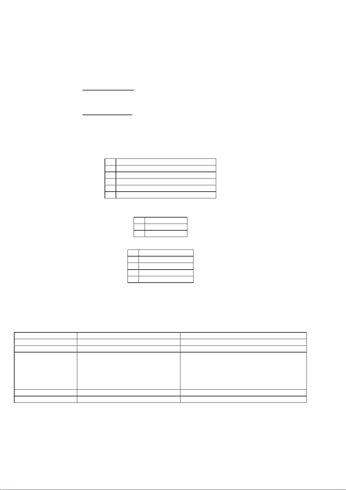
WMO2 G900 / G1800 / G1900
WCOM/GSM/WMO2/WMO2ATDOC Friday 21 May 1999
4.7 Supplementary Services commands
4.7.1 Call forwarding +CCFC
This commands allows control of the call forwarding supplementary
service.
Command syntax:
AT+CCFC= <reason>, <mode> [, <number> [,<type> [,<class>
[,<subaddr> [, <satype> [,<time> ] ] ] ] ] ]
Response syntax:
+CCFC: <status>, <class1> [, <number>, <type> [,<subaddr>,
<satype> [,<time> ] ] ]
[ <CR><LF>+CCFC: <status>, <class2> [, <number>, <type>
[,<subaddr>, <satype> [,<time> ] ] ]
[ … ] ]
* <reason>:
0 Unconditional
1 Mobile busy
2 No reply (<time> is used)
3 Not reachable
4 All call forwarding
5 All conditionnal call forwarding
* <mode>:
2 Interrogate
3 Registration
4 Erasure
* <class>:
1 Voice
2 Data
4 Fax
8 Short Messages
7 All classes
The combination of different classes in not supported, it will only result in
the activation / deactivation / status request of all classes (7).
* <subaddr>, <satype>: not managed
* <time>: For Call Barring on No Reply, time to wait (1 to 30) in seconds
before call is forwarded, default value is 20 seconds.
Application to GSM AT+CCFC=0,3, "0146290800" register call forwarding unconditional
GSM to application OK Command valid
Application to GSM AT+CCFC=0,2 Interrogate call forwarding unconditional
GSM to application +CCFC:1,1, "0146290800" ,129
<CR><LF>+CCFC:1,2, "0146290
call forwarding active for voice
call forwarding active for data
802",129
<CR><LF>+CCFC:1,4, "0146290
call forwarding active for fax
804" ,129
OK
Application to GSM AT+CCFC=0,4 erase call forwarding unconditional
GSM to application OK Command valid
The +CCFC responses are not sorted depending of the <class> parameter,
it only depends of the order of the network response.
WAVECOM confidential © 60
Page 67

WMO2 G900 / G1800 / G1900
WCOM/GSM/WMO2/WMO2ATDOC Friday 21 May 1999
4.7.2 Call barring +CLCK
This commands allows control of the call barring supplementary service.
Locking, unlocking or querying the status of a call barring is possible for all
or a specific class.
Command Syntax:
AT+CLCK= <fac>, <mode> [, <password> [, <class> ] ]
Response Syntax: (for <mode>=2 and command successful)
+CLCK: <status> [, <class1>
[ <CR><LF>+CLCK: <status>, <class2>
[ … ] ]
* <fac>:
"AO", "OI", "OX" for outgoing calls barring
"AI", "IR" for incoming calls barring
"AG", "AC", "AB" for all calls barring (<mode>=0 only)
*<mode>
0 unlocks the facility
1 locks the facility
2 query status
* <class>: see description for +CLCK command (Call Barring)
The combination of different classes in not supported, it will only result in
the activation / deactivation / status request of all classes (7).
Password code must be on 4 digits maximum.
Application to GSM AT+CLCK="AO",1,1234
GSM to application OK Command valid
Application to GSM AT+CLCK="AO",0,5555
GSM to application +CME ERROR: 16 Wrong password
Application to GSM AT+CLCK="AO",0,1234
GSM to application OK Command valid
4.7.3 Modify SS password +CPWD
This command shall be used by the application to change the
supplementary service password. The command to manage this
functionality is:
Command Syntax:
AT+CPWD=<fac>,<OldPassword>, <NewPassword>
for <fac> see +CLCK command with only “P2” facility added (SIM PIN2).
Application to GSM AT+CPWD="AO",1234,5555 change Call Barring password
GSM to application OK password changed
Application to GSM AT+CPWD="AO",1234,5555 Change password
GSM to application +CME ERROR: 16 wrong password
Application to GSM AT+CPWD="AO",5555,1234 change password
GSM to application OK password changed
WAVECOM confidential © 61
Page 68

WMO2 G900 / G1800 / G1900
WCOM/GSM/WMO2/WMO2ATDOC Friday 21 May 1999
4.7.4 Call waiting +CCWA
This command allows control of the call waiting supplementary service.
The module supports only one communication. If a call waiting call
happens, the module will disconnect it but with a +CCWA:
<TelNb>,<TonNpi> indication.
Command Syntax: AT+CCWA=<n>, [ <mode> [, <class> ] ]
Unsolicited message: +CCWA: <number>, <type> (for incoming call)
* <n>: Result code presentation status in the TA
0 Disable
1 Enable
* <mode>:
0 Disable
1 Enable
2 Query status
* <class>:
1 Voice
2 Data
4 Fax
8 Short Messages
7 All classes
The combination of different classes in not supported, it will only result in
the activation / deactivation / status request of all classes (7).
Application to GSM AT+CCWA=1,1,1 Enable call waiting for speech
GSM to application OK Command valid
Application to GSM AT+CCWA=1,2 Interrogate call waiting
GSM to application +CCWA:1,1
Call waiting active for speech calls
OK
Application to GSM +CCWA: "0146290800",145 Number of the incoming call while already in
communication
incoming call is disconnected without any
notification
Application to GSM AT+CCWA=1,0,7 erase call waiting for all classes
GSM to application OK command valid
WAVECOM confidential © 62
Page 69

WMO2 G900 / G1800 / G1900
WCOM/GSM/WMO2/WMO2ATDOC Friday 21 May 1999
4.7.5 Calling line identification restriction +CLIR
This command allows control of the calling line identification restriction
supplementary service.
Command syntax: AT+CLIR=<n>
Response syntax: +CLIR:<n>,<m> (for AT+CLIR?)
* <n>: parameter sets the adjustment for outgoing calls
0 Presentation indicator is used according to the subscription of the CLIR service
1 CLIR invocation
2 CLIR suppression
* <m>: parameter shows the subscriber CLIR status in the network
0 CLIR not provisioned
1 CLIR provisioned in permanent mode
2 Unknown (no network...)
3 CLIR temporary mode presentation restricted
4 CLIR temporary mode presentation allowed
Application to GSM AT+CLIR=2
GSM to application OK command valid
Application to GSM AT+CLIR? Ask for current functionality
GSM to application +CLIR: <n>,<y>OK<n> and <m> defined as above
4.7.6 Calling line identification presentation+CLIP
This command allows control of the calling line identification presentation
supplementary service:
Command syntax: AT+CLIP=<n>
Response syntax: +CLIP: <n>,<m> (for AT+CLIP?)
Unsolicited message: +CLIP: <number>, <type> (for incoming call)
* <n>: parameter sets/shows the result code presentation in the TA
0 disable
1 enable
• <m>: parameter shows the subscriber CLIP service status in the network
0 CLIP not provisioned
1 CLIP provisioned
2 Unknown (no network...)
Application to GSM AT+CLIP=1 Enable CLIP
GSM to application OK CLIP is enabled
Application to GSM AT+CLIP? Ask for current functionality
GSM to application +CLIP: <n>,<m>
OK
GSM to application RING
+CLIP: "0146290800",129
Application to GSM AT+CLIP=0 Disable CLIP presentation
GSM to application OK Command valid
<n> and <m> defined as above
Incoming call
Incoming call number presentation
WAVECOM confidential © 63
Page 70

WMO2 G900 / G1800 / G1900
WCOM/GSM/WMO2/WMO2ATDOC Friday 21 May 1999
4.7.7 Connected line identification presentation +COLP
This command allows control of the connected line identification
presentation supplementary service, useful in case of call forwarding of the
connected line.
Command syntax: AT+COLP=<n>
Response syntax: +COLP: <n>,<m> (for AT+COLP?)
Intermediate message: +COLP: <number>,<type> (after ATD)
<n>: parameter sets/shows the result code presentation status in the TA
0 Disable
1 Enable
<m>: parameter shows the subscriber COLP service status in the network
0 COLP not provisioned
1 COLP provisioned
2 Unknown (no network...)
Application to GSM AT+COLP=1 Activate COLP
GSM to application OK Command valid
Application to GSM AT+COLP? Ask for current functionality
GSM to application +COLP: 1,1
OK
Application to GSM ATD146290800; Outgoing call
GSM to application +COLP: "0146290928",129OKConnected outgoing line presentation
COLP is enabled and provisioned
Application to GSM AT+COLP=0 desactivate COLP
GSM to application OK command valid
WAVECOM confidential © 64
Page 71

WMO2 G900 / G1800 / G1900
WCOM/GSM/WMO2/WMO2ATDOC Friday 21 May 1999
4.7.8 Advice of charge +CAOC
Command syntax: AT+CAOC= <mode>
This refers to Advice of Charge supplementary service (GSM 02.24 [] and
GSM 02.86 []) that enables subscriber to get information about the cost of
calls. With <mode>=0, the execute command returns the current call meter
value (CCM) from the ME.
If AOC is supported, the command also includes the possibility to enable an
unsolicited event reporting of the CCM information.
The unsolicited result code +CCCM: <ccm> is sent when the CCM value
changes. Deactivation of the unsolicited event reporting is made with the
same command.
If AOC is supported, the Read command indicates whether the unsolicited
reporting is activated or not.
Defined values
<mode>:
0 query CCM value
1 deactivate the unsolicited reporting of CCM value
2 activate the unsolicited reporting of CCM value
<ccm>:
string type; three bytes of the current call meter value in hexadecimal
format
(e.g. "00001E" indicates decimal value 30); value is in home units and bytes are
similarly coded as ACMmax value in the SIM
Application to GSM AT+CAOC=0 Query CCM value
GSM to application +CAOC: "000A08"OKDisplay Current Call Meter value (CCM = 2568)
Application to GSM AT+CAOC=1 Deactivate unsolicited report of CCM value
GSM to application OK CCM report deactivated
Application to GSM AT+CAOC=2 Activate unsolicited report of CCM value
GSM to application OK CCM report activated
Application to GSM AT+CAOC ? Request mode
GSM to application +CAOC: <mode>
Display unsolicited report mode (1 or 2)
OK
Application to GSM AT+CAOC= ? Request supported modes
GSM to application +CAOC: (0-2)
0,1,2 modes supported
OK
4.7.9 Accumulated call meter +CACM
Set command resets the Advice of Charge related accumulated call meter
value in SIM file EF
both the current and preceding calls. SIM PIN2 is required to reset the
value. If setting fails in an ME error, +CME ERROR: <err> is returned.
Read command returns the current value of ACM.
Then ACM value (entered or displayed) is in hexadecimal format with 6
digits.
Application to GSM AT+CACM ? Request ACM value
GSM to application +CACM: "000400"OKDisplay ACM value
Application to GSM AT+CACM= 1234 Request ACM reset, real PIN2 is "1234"
GSM to application OK ACM value is reset
Application to GSM AT+CACM= 0000 Request ACM reset with wrong PIN2 value
GSM to application +CME ERROR: 17 SIM PIN2 required
Application to GSM AT+CACM ? Request ACM value
GSM to application +CACM: "000000"OKDisplay ACM value
. ACM contains the total number of home units for
ACM
(ACM = 1024)
(ACM = 0)
WAVECOM confidential © 65
Page 72

WMO2 G900 / G1800 / G1900
WCOM/GSM/WMO2/WMO2ATDOC Friday 21 May 1999
4.7.10 Accumulated call meter maximum +CAMM
Set command sets the Advice of Charge related accumulated call meter
maximum value in SIM file EF
. ACMmax contains the maximum
ACMmax
number of home units allowed to be consumed by the subscriber. When
ACM (refer +CACM) reaches ACMmax, then calls are prohibited. SIM PIN2 is
required to set the value. If setting fails in an ME error, +CME ERROR: <err> is
returned.
Read command returns the current value of ACMmax.
Them ACMmax value (entered or displayed) is in hexadecimal format with
6 digits.
Application to GSM AT+CAMM= "000400", 1234 Request ACMmax update, real PIN2 is
"1234"
GSM to application OK ACMmax updated to 1024
Application to GSM AT+CAMM= "000400",0000 Request ACMmax update, real PIN2 is
"1234"
GSM to application +CME ERROR: 17 SIM PIN2 required
Application to GSM AT+CAMM ? Request ACMmax value
GSM to application +CAMM: "000400"
ACMmax=1024
OK
4.7.11 Price per unit and currency table +CPUC
Description
Set command sets the parameters of Advice of Charge related price per unit
and currency table in SIM file EF
convert the home units (as used in +CAOC, +CACM and +CAMM) into currency
units. SIM PIN2 is required to set the parameters. If setting fails in an ME
error, +CME ERROR: <err> is returned.
Application to GSM AT+CPUC= "FFR", "0.82", 1234 Request Currency and Price per unit
GSM to application OK
Application to GSM AT+CPUC= "FFR", "0.82", 1111 Request Currency and PPU update (wrong
GSM to application +CME ERROR: 17 SIM PIN2 required
Application to GSM AT+CPUC? Request Currency & Price
GSM to application +CPUC: "FFR", "0.82"
OK
. PUCT information can be used to
PUCT
update
PIN2)
Currency= "FFR"
Price per unit= "0.82"
WAVECOM confidential © 66
Page 73

WMO2 G900 / G1800 / G1900
WCOM/GSM/WMO2/WMO2ATDOC Friday 21 May 1999
4.8 Data commands
4.8.1 Bearer type selection +CBST
Command syntax: AT+CBST= <speed>, <name>, <ce>
No data compression is provided and only asynchronous modem is
supported (<name> = 0).
<speed> Description Modem type
0 Autobauding None
1 (*) 300 bps V.21
2 (*) 1200 bps V.22
3 (*) 1200/75 bps V.23
4 2400 bps V.22bis
5 2400 bps V.26ter
6 4800 bps V.32
7 9600 bps V.32
8 Specific
65 (*) 300 bps V.110
66 (*) 1200 bps V.110
68 2400 bps V.110
70 4800 bps V.110
71 9600 bps V.110
(*) Only for non transparent mode
<ce> Connection element
0 Transparent only
1 Non transparent only
2 Transparent preferred
3 Non transparent preferred
Application to GSM AT+CBST=7,0,1 ask for a bearer
GSM to application OK bearer supported
Application to GSM AT+CBST=81,0,0 ask for a bearer
GSM to application +CME ERROR: 4 bearer not supported
This command applies to both outgoing and incoming data calls but in a
different way. For outgoing call the two parameters (e.g. <speed> and
<ce>) apply, whereas for incoming call only the <ce> parameter applies.
Note 1) as far as incoming calls are concerned, if <ce> is set to T only and
the network proposes NT only or vice versa then the call is released.
Note 2) older values 100 and 101 for <ce> are retained for compatibility
purpose but shallnot be used anymore, values 2 and 3 shall be used
instead.
4.8.2 Service reporting control +CR
This command enables a more detailed service reporting, in case of data
outgoing call. Before sending the CONNECT response to the application,
the GSM module will precise the type of data connection that have been
established.
These report types are:
+CR: ASYNC for asynchronous transparent
+CR: REL ASYNC for asynchronous non-transparent
Application to GSM AT+CR=0 extended reports disabled
GSM to application OK command valid
Application to GSM AT+CR=1 extended reports enabled
GSM to application OK command valid
Default value is stored in E2PROM.
WAVECOM confidential © 67
Page 74

WMO2 G900 / G1800 / G1900
WCOM/GSM/WMO2/WMO2ATDOC Friday 21 May 1999
4.8.3 Cellular result codes +CRC
This command enables a more detailed ring indication, in case of incoming
call (voice or data). Instead of the string "RING", an extended string is used
to indicate which type of call is ringing (e.g. +CRING: VOICE).
These extended indications are:
+CRING: ASYNC for asynchronous transparent
+CRING: REL ASYNC for asynchronous non-transparent
+CRING: VOICE for normal speech.
+CRING: FAX for fax calls
Application to GSM AT+CRC=0 extended reports disabled
GSM to application OK command valid
Application to GSM AT+CRC=1 extended reports enabled
GSM to application OK command valid
4.8.4 Radio link protocol parameters +CRLP
This command allows to change the radio link protocol parameters used for
non transparent data transmission.
Command syntax: AT+CRLP=<up-window_size>,<down-
window_size>,<acknowledgement-timer>,
<retransmission_attempts>, <reset_allowed>
Application to GSM AT+CRLP=10,10,90,10,0 set new parameters
GSM to application OK Command valid
Application to GSM AT+CRLP? Current values
GSM to application AT+CRLP: 10,10,90,10
OK
Command valid
WAVECOM confidential © 68
Page 75

WMO2 G900 / G1800 / G1900
WCOM/GSM/WMO2/WMO2ATDOC Friday 21 May 1999
4.9 V24-V25 commands
4.9.1 Fixed DTE rate +IPR
This commands specifies the data rate at which the DCE will accept
commands.
Application to GSM AT+IPR?
GSM to application +IPR: 9600
OK
Application to GSM AT+IPR=?
GSM to application +IPR:(0,2400, 4800, 9600, 19200) ,
(300,600,38400,57600,115200)
OK
Application to GSM AT+IPR=38400
GSM to application OK disable autobauding and set
Application to GSM AT+IPR=0
GSM to application OK enable autobauding
Note (1): first set of values indicates the range of autodetectable speeds.
The second set of values indicates all the possible speeds which can be
used by DCE.
An autobauding is provided which operates from 2400 to 19200 baud.
However some constraints have to be dealt with:
• any AT command issued by DTE must start with a capital ‘A’ and
‘T’ (or ‘\’). If not, DCE may send back some garbagge characters
and get de-synchronized. Shoud it happen, DTE shall just issue
once or twice ‘AT\r’ (at 2400 or 4800 baud) or just ‘AT’ (at 9600
baud) to get the modem re-synchronized.
• the DTE shall wait for 1ms after receipt of the last character of the
AT response (which is always ‘\n’ or 0x0A) to send a new AT
command at either the same rate or a new rate. Shoud this delay
ignored, DCE can get de-synchronised. Once again, sending once
or twice ‘AT\r’ or just ‘AT’ causes the DCE to recover.
Be careful: at start-up if autobauding is enabled and no AT command has
been received yet, the module sends all unsolicited responses (like RING) at
9600 baud.
current rate is 9600 bps
possible values (1)
rate to 38400 bps
WAVECOM confidential © 69
Page 76

WMO2 G900 / G1800 / G1900
WCOM/GSM/WMO2/WMO2ATDOC Friday 21 May 1999
4.9.2 DTE-DCE character framing +ICF
This command is used to determine the local serial port start-stop
(asynchronous) character framing that the DCE shall use.
Command syntax: AT+ICF= <format>, <parity>
* <format>:
0 Autodetect not supported
1 8 Data 2 Stop supported
2 8 Data 1 Parity 1 Stop supported
3 8 Data 1 Stop supported
4 7 Data 2 Stop supported
5 7 Data 1 Parity 1 Stop supported
6 7 Data 1 Stop supported
* <parity>:
0 Odd supported
1 Even supported
2 Mark supported
3 Space supported
4 None supported
Note 1) setting a character framing different from 8N1 will disable
autobauding (in the case it was activated). However setting it back to 8N1
will not re-enable autobaud.
Note 2) setting the framing to 8N1 will let the autobauding enabled, if it
was already enabled (implying framing was already 8N1).
Application to GSM AT+ICF?
GSM to application +ICF: 3,4
current values
OK
Application to GSM AT+ICF=?
GSM to application +ICF: (1-6),(0-4)OKpossible values.
Application to GSM AT+ICF=0,0
GSM to application OK new values
WAVECOM confidential © 70
Page 77

WMO2 G900 / G1800 / G1900
WCOM/GSM/WMO2/WMO2ATDOC Friday 21 May 1999
4.9.3 DTE-DCE local flow control +IFC
This command is used to control the operation of local flow control
between the DTE and DCE.
AT+IFC=<DCE_by_DTE>,<DTE_by_DCE>
* < DCE_by_DTE >:
0 none supported
1 Xon/Xoff local circuit 103 not supported
2 RTS supported
3 Xon/Xoff global on circuit 103 not supported
Important note: when this parameter is set to 2 (DTE invokes flow control
through RTS) the behavior of the DCE is the following:
If the DCE has never detected RTS in high (or ON) condition since startup
then it ignores RTS, assuming this signal is not connected.
As soon as DCE detects RTS high, then this signal acts upon it. Therefore
subsequent RTS transition to OFF will prevent DCE from sending any
further data in online and in offline as well.
This behavior allows the user to use the default settings (hardware flow
control) and let RTS disconnected. In the case RTS is connected and is high
at least once then it acts upon DCE.
* < DTE_by_DCE >:
0 none supported
1 Xon/Xoff circuit 104 not supported
2 CTS Supported
When this parameter is set to 0 (none) then CTS is kept high all the time.
Application to GSM AT+IFC?
GSM to application +IFC: 2,2
current values
OK
Application to GSM AT+IFC=?
GSM to application +IFC: (2),(2)OKpossible values.
Application to GSM AT+IFC=0,0
GSM to application OK new values
4.9.4 Set DCD signal &C
This commands controls the Data Carrier Detect (DCD) signal.
Application to GSM AT&C0 DCD always on
GSM to application OK command valid
Application to GSM AT&C1 DCD matches state of the remote modem's data carrier
GSM to application OK command valid
4.9.5 Set DTR signal &D
This commands controls the Data Terminal Ready (DTR) signal.
Application to GSM AT&D0 the DTR signal is ignored
GSM to application OK command valid
Application to GSM AT&D1 Modem switches from data to command mode when DTR
switches from ON to OFF
GSM to application OK command valid
Application to GSM AT&D2 Upon DTR switch from ON to OFF, the call is cleardown
GSM to application OK command valid
WAVECOM confidential © 71
Page 78

WMO2 G900 / G1800 / G1900
WCOM/GSM/WMO2/WMO2ATDOC Friday 21 May 1999
4.9.6 Set DSR signal &S
This commands controls the Data Set Ready (DSR) signal.
Application to GSM AT&S0 DSR always on
GSM to application OK command valid
Application to GSM AT&S1 DSR off in command mode, DSR on in data mode
GSM to application OK command valid
4.9.7 Back to online mode O
If you have established a connection and the mobile is in online command
mode, this command allows to return to online data mode.
Application to GSM ATO
GSM to application OK Command valid
4.9.8 Result code suppression Q
Determines whether the mobile sends result codes or not
Application to GSM ATQ0 DCE transmits result codes
GSM to application OK Command valid
Application to GSM ATQ1 Result codes are suppressed and not transmitted
GSM to application (none) no response
4.9.9 DCE response format V
Determines the DCE response format, with or without header characters
<CR><LF>, and with the use of numeric result codes.
V0 V1
Information responses <text><CR><LF> <CR><LF>
<text><CR><LF>
Result codes <numeric code><CR> <CR><LF>
<verbose code><CR><LF>
Application to GSM ATV0 DCE transmits limited headers and trailers and numeric result codes
GSM to application 0 command is valid (0 means OK)
Application to GSM ATV1 DCE transmits full headers and trailers and verbose response text
GSM to application OK command is valid
4.9.10 Default configuration Z
Restores the configuration profile.
Application to GSM ATZ
GSM to application OK Command valid
4.9.11 Save configuration &W
This commands writes the active configuration to a non-volatile memory
(EEPROM). Description of the stored parameters is in Erreur! Source duErreur! Source du
renvoi introuvable.renvoi introuvable.
Application to GSM AT&W Writes current configuration to E2prom
GSM to application OK command valid
WAVECOM confidential © 72
Page 79

WMO2 G900 / G1800 / G1900
WCOM/GSM/WMO2/WMO2ATDOC Friday 21 May 1999
4.9.12 Auto-tests &T
AT&T0 is used to perform auto-tests. The response will be OK if no
software problem is detected (E2P, RAM and ROM checksums), otherwise
a simple ERROR response is sent.
AT&T1 is used to close the audio loop, and AT&T2 is used to open the
audio loop. This is used to validate the audio loop (microphone to speaker).
Application to GSM AT&T0 Perform software auto-tests
GSM to application OK No software problem detected, all checksums are correct
Application to GSM AT&T1 Do the audio loop test (close)
GSM to application OK command valid
Application to GSM AT&T2 Stop the audio loop test (open)
GSM to application OK command valid
4.10 Specific AT commands
4.10.1 Cell environment description +CCED
This command can be used by the application to retrieve the cell
parameters of the main cell and of up to six neighbour cells.
Two ways may exist for the external application to know these cell
parameters: on request of the application, or automatically by the module
every 5 seconds.
The automatic mode is not supported during communication or
registration.
The command to manage this functionality is:
Command syntax: AT+CCED=<mode>[, <requested dump>]
* <mode>:
0 One shot requested
1 Automatic shots requested
2 Stop automatic shots
* <requested dump>:
1 Main Cell:
MCC, MNC, LAC, CI, BSIC,
BCCH Freq (absolute), RxLev,
RxLev Full, RxLev Sub,
RxQual, RxQual Full, RxQual
Sub,Idle TS
2 Neighbour1 to Neighbour6:
MCC, MNC, LAC, CI, BSIC,
BCCH Freq (absolute), RxLev
4 Timing Advance
Combination (addition of the values) of the requested dumped are
supported.
Notice that in idle mode, only RxLev measures (one the main cell and on
the neighbour cells) are done. The value of these RxLev is set in the RxLev
Full field for the main cell.
The response will be:
+CCED:<value>, ... , <value>
OK
Where <value> is the ASCII string of the values (in hexadecimal) of the
parameters. If a field can not be measured - or has no sense - the
parameter is not filled (two consecutive commas are then found).
WAVECOM confidential © 73
Page 80

WMO2 G900 / G1800 / G1900
WCOM/GSM/WMO2/WMO2ATDOC Friday 21 May 1999
4.10.2 Automatic RxLev indication +CCED
The CCED command has been extended to indicate the the received signal
strength indication (rssi) of the main cell. The principle of the command is
not changed:
Command Syntax: AT+CCED=<mode>[, <requested dump>]
* <mode>:
0 One shot requested
1 Automatic shots requested
2 Stop automatic shots
* <requested dump>:
8 Main cell RSSI indications (RxLev) from 0 to 31
The response will be a +CSQ answer and not a +CCED answer. The 07.07
format for the +CSQ is respected. The <ber> is not evaluated by this
command, so the <ber> value will always be 99.
+CSQ:<rssi>, 99
OK
This +CSQ answer, when automatic shots are selected, is sent every time
the <rssi> measured by the module changes. This automatic shots are
supported in idle mode and during communication.
Combination (addition of the values) of the requested dumped (1,2,4,8) are
supported. Both answer +CCED and +CSQ may be then generated.
WAVECOM confidential © 74
Page 81

WMO2 G900 / G1800 / G1900
WCOM/GSM/WMO2/WMO2ATDOC Friday 21 May 1999
4.10.3 General Indications +WIND
Wavecom introduced a general mechanism to send unsollicited non
standardized indication to the customer application. The yet identified
unsollicited non standardized indications are:
- indication of a physical change on the SIM presence pin from
connector (meaning SIM inserted, SIM removed)
- indication during a mobile originated call establishement, that the
calling party is ringing.
- Indication of the availability of the module, after boot, to receive AT
commands
For each of these indications, a “bit flow” has to be indicated. The syntax of
the command is:
Command syntax: AT+WIND= <IndLevel >
<IndLevel> IndicationIndication
1 Hardware SIM Insert / Remove indications (Rack open/close)
2 Calling party alert indication
4 Module is ready to treat AT commands (except phonebooks, AOC, SMS), but still in
emergency mode.
8 Indication that the module is ready to treat all AT commands, at te end of init, or
after ADN / FDN swap
If <IndLevel> is equal to 0 (default value), no unsolicited
“+WIND: <IndNb>” will occur.
Combination (addition of the values) shall be used to allow more than one
indication flow.
The answer is OK if the value are in the previous range.
The unsolicited answer will then be:
+WIND: <indicated event>
The yet defined indicated event list is:
<event> Meaning
0 The SIM presence pin has been detected as “SIM removed” (depending from the 0 bit
flow)
1 The SIM presence pin has been detected as “SIM inserted”
2 Calling party is alerting
3 Module is ready to treat AT commands (except phonebooks, AOC, SMS), at init or after
AT+CFUN=1
4 Module is ready to treat all AT commands, end of phonebook init or swap (ADN to
FDN, or FDN to ADN)
AT+WIND? Command is supported and indicates the <allowed bit flows>.
AT+WIND is automatically stored in e2p. This means the &W commands
has not to be used. And the selected flows are always activated after boot.
Default value is 0: No flow activated. No indication.
4.10.4 Data ciphering mode between ME and MSC +ALEA
This command is used to get a random value from the mobile station and
to reenter it codes by the DES algorithm. In the way Application to GSM, an
"h" character shall be added before the value.
Application to GSM AT+ALEA? get random value
GSM to Application AT+ALEA=1234567890123456
OK
Application to GSM AT+ALEA=hA125B348ABCDEF9 value coded
GSM to Application +ALEA=9876543210FBCADE0
OK
Application to GSM AT+ALEA=h12335678902234AB new coded value
GSM to Application NO CARRIER coded value false
command valid
value coded valid
new random value sent
communication hang up
WAVECOM confidential © 75
Page 82

WMO2 G900 / G1800 / G1900
WCOM/GSM/WMO2/WMO2ATDOC Friday 21 May 1999
4.10.5 Data ciphering mode +CRYPT
This command enables or disables the data ciphering (D.E.S algorithm) of
the PIN and a random value sent periodically in order to insure a more
secure communication.
Application to GSM AT+CRYPT=0 Ciphering off
GSM to Application OK command valid
Application to GSM AT+CRYPT=1 Ciphering on
GSM to Application OK command valid
4.10.6 Key management +EXPKEY
This command is used to enter the key used in the D.E.S algorithm to
cipher the data (PIN ). In the way Application to GSM, an "h" character shall
be added before the value.
Application to GSM AT+EXPKEY? Is a key stored in E2PROM?
GSM to Application +EXPKEY: NO KEY key is absent
Application to GSM AT+EXPKEY=h0111011101110111 new key entered
GSM to Application OK command valid
Application to GSM AT+EXPKEY? Is a key stored in E2PROM?
GSM to Application +EXPKEY: READY key is present
4.10.7 Informations on PLMN +CPLMN
This command returns the status and the number of all PLMNs seen by the
mobile. It also indicates the BCCH frequency number (absolute) of the
strongest cell and its RxLev
Application to GSM AT+CPLMN=?
GSM to application +CPLMN: (2,20810,122,50),
(0,20801,64,53)
OK
as defined as AT+COPS=? in the
GSM TS 07 07
4.10.8 Analog digital converters measurements +ADC
This command allows to get the DC level of ADC A and ADC B (those
voltages are coded on 8 bits from 0.5 V to 4.5 V ). Those values are
updated every 10 seconds.
Application to GSM AT+ADC?
GSM to application +ADC: 5,4OKADC A , ADC B
4.10.9 Mobile Equipment event reporting +CMER
This command enabled or disables sending of unsolicited result codes in
the case of key pressing.
Command Syntax: AT+CMER=<mode>,<keyp>,<disp>,<ind>,<bfr>
<keyp> (keypad):
0 No keypad event reporting.
1 Keypad event reporting are routed using unsolicited code:
+CKEV: <key>, <press>
<press>
1: key press
0: key release
<key>: Keyboard map is (5,5)
0 1 2 3 4
5 6 7 8 9
10 11 12 13 14
15 16 17 18 19
20 21 22 23 24
WAVECOM confidential © 76
Page 83

WMO2 G900 / G1800 / G1900
WCOM/GSM/WMO2/WMO2ATDOC Friday 21 May 1999
4.10.10 Read Language Preference +WLPR
Command syntax: AT+WLPR= <index >
Response syntax: +WLPR: <value>
Read a Language Preference value of EF-LP. The first indexes sould have
the highest priority.
Application to GSM AT+WLPR? Read command
GSM to application +WLPR: 4
OK
Application to GSM AT+WLPR=1 Read first EF-LP index value
GSM to application +WLPR: 5
OK
Four language preference are available in EF-LP
Language preference is 5
4.10.11 Write Language Preference+WLPW
Command syntax: AT+WLPW=<index >,<value>
Response syntax: OK or +CME ERROR: <err>
Write a Language Preference value in EF-LP
Application to GSM AT+WLPW=1,5 Write Lang Pref equal to 5 in EF-LP with index 1
GSM to application OK EF-LP correctly updated
4.10.12 Read GPIO value +WIOR
Command syntax: AT+WIOR=<index >
Response syntax: +WIOR: <value>
Set the I/O port as an input and read the I/O pin, 0 if the pin is reset, 1 if the
pin is set. Eight I/O ports are available, so the <index> value is between 0
and 7.
Application to GSM AT+WIOR=4 Read I/O (number 4) value
GSM to application +WIOR: 0
OK
GPIO number 4 is reset
4.10.13 Write GPIO value +WIOW
Command syntax: AT+WIOW=<index >,<value>
Response syntax: OK
Set the I/O port as an output with a I/O pin value, 0 for reset, 1 for set
Application to GSM AT+WIOW=4,0 Reset I/O (number 4)
GSM to application OK GPIO value is written
4.11 Other AT commands
4.11.1 V.25 ter recommandation
Other remaining basic commands are not implemented, so an "ERROR"
string will be sent back.
All commands about modulation control, error control and data
compression are not recognized. An "ERROR" string will be sent back.
4.11.2 GSM 07.05 recommandation
All the remaining commands are not implemented, so an "ERROR" string
will be sent back.
4.11.3 GSM 07.07 recommandation
All the remaining commands are not implemented, so an "ERROR" string
will be sent back.
WAVECOM confidential © 77
Page 84

WMO2 G900 / G1800 / G1900
WCOM/GSM/WMO2/WMO2ATDOC Friday 21 May 1999
4.12 Fax Management commands
The fax service provided by the module is class 1 compatible. However only
the core commands defined by ITU T.31 are supported. These are:
• AT+FRH=3, AT+FRH=?,
• AT+FTH=3, AT+FTH=?,
• AT+FRM=24,48,72,96, AT+FRM= ?,
• AT+FTM=24,48,72,96, AT+FTM= ?,
• AT+FRS= <any duration>,
• AT+FTS= <any duration>.
It means that commands like AT+FAR, +FCC,... are not supported.
4.12.1 Setting up the module for fax
When autobauding is enabled, nothing special has to be done. However
when not enabled, proceed as described below to set up the module for
fax.
The GSM unit as well as the PC fax application have to be properly set up
prior to sendind/receiving faxes.
The only thing to do is to change the serial link rate as follows:
a) Launch any terminal application on PC and set it up to 9600 baud.
b) From the terminal application type in: AT+IPR = 2400; &W <enter>
The GSM unit should reply OK (if not, type in 'AT<enter>' as long as it does
not answer 'OK' and start again stage b).
4.12.2 Setting up the PC fax application:
The recommended fax application is Delrina WinFax v8.0.
It should be configured as follows (menu Setup/Fax Modem Setup):
♦ Port: any com
♦ Model: Generic Class 1 (hardware flow control). A generic class 1
with software flow control can be also selected.
♦ Init: default string is suitable for the module
♦ Reset: default string is suitable for the module
♦ Maximum Transmit Rate: 9600 baud (if higher then rate will be
automatically cut back to 9600 baud).
Others settings are of no relevance for the GSM unit: they can be modified.
4.12.3 Restoring the module's default profile for data call.
As for setting up the module for fax, the following instructions are
irrelevant if autobauding is enabled.
If the module is configured as stated in 10.1 then the serial rate is 2400
baud which of course limits the overall thoughput in support of 4800/9600
data calls.
Therefore, the serial rate should be set back to 9600 (or better 19200) baud
by issueing: AT+IPR = 9600; &W <enter>
WAVECOM confidential © 78
Page 85

WMO2 G900 / G1800 / G1900
WCOM/GSM/WMO2/WMO2ATDOC Friday 21 May 1999
5 Miscellaneous
5.1 Disclaimer
Modem and GSM-unit specifications and manuals are subject to change
without notice. Wavecom assumes no liability for damage incurred directly
or indirectly from errors, omissions or discrepancies between the modem or
GSM-unit and their manuals.
5.2 Trademarks
Some mentioned products are registered trademarks of them respective
companies.
5.3 Copyright
This manual is copyrighted by Wavecom with all rights reserved. No part of
this manual may be reproduced in any form without the prior written
permission of Wavecom.
No patent liability is assumed with respect to the use of the information
contained herein.
Wavecom 1999. All rights reserved.
WAVECOM confidential © 79
Page 86

WMO2 G900 / G1800 / G1900
WCOM/GSM/WMO2/WMO2ATDOC Friday 21 May 1999
6 Appendices
6.1 ME error result code: +CME ERROR: <error>
<error> Meaning Resulting from the following commands
3 Operation not allowed All GSM 07.07 commands (+CME ERROR: 3)
4 Operation not supported All GSM 07.07 commands (+CME ERROR: 4)
5 PH-SIM PIN required (SIM lock) All GSM 07.07 commands (+CME ERROR: 5)
10 SIM not inserted All GSM 07.07 commands (+CME ERROR: 10)
11 SIM PIN required All GSM 07.07 commands (+CME ERROR: 11)
12 SIM PUK required All GSM 07.07 commands (+CME ERROR: 12)
13 SIM failure All GSM 07.07 commands (+CME ERROR: 13)
16 Incorrect password +CACM, +CAMM, +CPUC, +CLCK, +CPWD,
+CPIN, +CPIN2 (+CME ERROR: 16)
17 SIM PIN2 required +CPBW (FDN), +CLCK (FDN),
18 SIM PUK2 required +CACM, +CAMM, +CPUC, +CPBW (FDN), +CPIN,
+CPIN2, +CLCK (FDN), +CPWD
20 Memory full +CPBW
21 Invalid index +CPBR, +CPBW, ATD>index
22 Not found +CPBF, +CPBP, +CPBN, +CGSN, +WOPN
24 Text string too long +CPBW, +IMEI, +CPIN, +CPIN2, +CLCK, +CPWD
26 Dial string too long +CPBW, ATD, +CCFC
30 No network service +VTS, +COPS=?, +CPLMN, +CLCK, +CCFC,
+CCWA
40 Network personalisation PIN
required (Network lock)
All GSM 07.07 commands (+CME ERROR: 40)
6.2 Message service failure result code: +CMS
ERROR: <er>
<er> is defined as below:
<er> Meaning Resulting from the following commands
1 to 127 Error cause values from the
GSM recommendation 04.11
Annex E-2
301 SMS service of ME reserved +CSMS (with +CMS: ERROR 301)
302 Operation not allowed All SMS commands (+CMSS, +CMGL, +CPMS,
303 Operation not supported All SMS commands
304 Invalid PDU mode parameter +CMGS, +CMGW,
305 Invalid text mode parameter +CMGS, +CMGW, +CMSS
310 SIM not inserted All SMS commands
311 SIM PIN required All SMS commands
312 PH-SIM PIN required All SMS commands
313 SIM failure All SMS commands
316 SIM PUK required All SMS commands
317 SIM PIN2 required All SMS commands
318 SIM PUK2 required All SMS commands
321 Invalid memory index +CMGR, +CMSS, +CMGD, +CMGL
322 SIM memory full +CMGW
330 SC address unknown +CSCA?, +CMSS, +CMGS
+CMGS, +CMSS
+CSMP…
WAVECOM confidential © 80
Page 87

WMO2 G900 / G1800 / G1900
WCOM/GSM/WMO2/WMO2ATDOC Friday 21 May 1999
6.3 Specific error result codes
<error> Meaning Resulting from the following commands
512 MM establishment failure (for
SMS)
513 Lower layer failure (for SMS) +CMGS, +CMSS
514 CP error (for SMS) +CMGS, +CMSS
515 Please wait, init or command
processing in progress
+CMGS, +CMSS (+CMS ERROR: 512)
All commands ( “+CME ERROR: 515” or “+CMS
ERROR: 515”)
WAVECOM confidential © 81
Page 88

WMO2 G900 / G1800 / G1900
WCOM/GSM/WMO2/WMO2ATDOC Friday 21 May 1999
6.4 IE Cause values from GSM 04.08 recommendation
Cause value Diagnostic
1 Unassigned (unallocated) number
3 No route to destination
6 Channel unacceptable
8 Operator determined barring
16 Normal call clearing
17 User busy
18 No user responding
19 User alerting, no answer
21 Call rejected
22 Number changed
26 Non selected user clearing
27 Destination out of order
28 Invalid number format (incomplete number)
29 Facility rejected
30 Response to STATUS ENQUIRY
31 Normal, unspecified
34 No circuit/channel available
38 Network out of order
41 Temporary failure
42 Switching equipment congestion
43 Access information discarded
44 Requested circuit/channel not available
47 Resources unavailable, unspecified
49 Quality of service unavailable
50 Requested facility not subscribed
55 Incoming calls barred with in the CUG
57 Bearer capability not authorized
58 Bearer capability not presently available
63 Service or option not available, unspecified
65 Bearer service not implemented
68 ACM equal to or greater than ACMmax
69 Requested facility not implemented
70 Only restricted digital information bearer capability is available
79 Service or option not implemented, unspecified
81 Invalid transaction identifier value
87 User not member of CUG
88 Incompatible destination
91 Invalid transit network selection
95 Semantically incorrect message
96 Invalid mandatory information
97 Message type non-existent or not implemented
98 Message type not compatible with protocol state
99 Information element non-existent or not implemented
100 Conditional IE error
101 Message not compatible with protocol state
102 Recovery on timer expiry
111 Protocol error, unspecified
127 Interworking, unspecified
252 Call barring on outgoing calls
253 Call barring on incoming calls
254 Call impossible
255 Lower layer failure
WAVECOM confidential © 82
Page 89

WMO2 G900 / G1800 / G1900
WCOM/GSM/WMO2/WMO2ATDOC Friday 21 May 1999
All other values in the range 0 to 31 shall be treated as cause 31.
All other values in the range 32 to 47 shall be treated as cause 47.
All other values in the range 48 to 63 shall be treated as cause 63.
All other values in the range 64 to 79 shall be treated as cause 79.
All other values in the range 80 to 95 shall be treated as cause 95.
All other values in the range 96 to 111 shall be treated as cause 111.
All other values in the range 112 to 127 shall be treated as cause 127.
WAVECOM confidential © 83
Page 90

WMO2 G900 / G1800 / G1900
WCOM/GSM/WMO2/WMO2ATDOC Friday 21 May 1999
6.5 GSM 04.11 Annex E-2: Mobile originating
SM-transfer
These error causes could appear for SMS commands (+CMGS, +CMSS,
+CMGD…)
Cause no 1: "Unassigned (unallocated) number"
This cause indicates that the destination requested by the Mobile Station
cannot be reached because, although the number is in a valid format, it is
not currently assigned (allocated).
Cause no 8: "Operator determined barring"
This cause indicates that the MS has tried to send a mobile originating
short message when the MS's network operator or service provider has
forbidden such transactions.
Cause no 10: "Call barred"
This cause indicates that the outgoing call barred service applies to the
short message service for the called destination.
Cause no 21: "Short message transfer rejected"
This cause indicates that the equipment sending this cause does not wish
to accept this short message, although it could have accepted the short
message since the equipment sending this cause is neither busy nor
incompatible.
Cause no 27: "Destination out of service"
This cause indicates that the destination indicated by the Mobile Station
cannot be reached because the interface to the destination is not
functioning correctly. The term "not functioning correctly" indicates that a
signalling message was unable to be delivered to the remote user; e.g., a
physical layer or data link layer failure at the remote user, user equipment
off-line, etc.
Cause no 28: "Unidentified subscriber"
This cause indicates that the subscriber is not registered in the PLMN (i.e.
IMSI not known)
Cause no 29: "Facility rejected"
This cause indicates that the facility requested by the Mobile Station is not
supported by the PLMN.
Cause no 30: "Unknown subscriber"
This cause indicates that the subscriber is not registered in the HLR (i.e.
IMSI or directory number is not allocated to a subscriber).
Cause no 38: "Network out of order"
This cause indicates that the network is not functioning correctly and that
the condition is likely to last a relatively long period of time; e.g.,
immediately reattempting the short message transfer is not likely to be
successful.
Cause no 41: "Temporary failure"
This cause indicates that the network is not functioning correctly and that
the condition is not likely to last a long period of time; e.g., the Mobile
Station may wish to try another short message transfer attempt almost
immediately.
Cause no 42: "Congestion"
This cause indicates that the short message service cannot be serviced
because of high traffic.
Cause no 47: "Resources unavailable, unspecified"
This cause is used to report a resource unavailable event only when no
other cause applies.
Cause no 69: "Requested facility not implemented"
This cause indicates that the network is unable to provide the requested
short message service.
Cause no 81: "Invalid short message transfer reference value"
This cause indicates that the equipment sending this cause has received a
message with a short message reference which is not currently in use on
the MS-network interface.
Cause no 95: "Invalid message, unspecified"
This cause is used to report an invalid message event only when no other
cause in the invalid message class applies.
WAVECOM confidential © 84
Page 91

WMO2 G900 / G1800 / G1900
WCOM/GSM/WMO2/WMO2ATDOC Friday 21 May 1999
Cause no 96: "Invalid mandatory information"
This cause indicates that the equipment sending this cause has received a
message where a mandatory information element is missing and/or has a
content error (the two cases are undistinguishable).
Cause no 97: "Message type non-existent or not implemented"
This cause indicates that the equipment sending this cause has received a
message with a message type it does not recognize either because this is a
message not defined or defined but not implemented by the equipment
sending this cause.
Cause no 98: "Message not compatible with short message protocol state"
This cause indicates that the equipment sending this cause has received a
message such that the procedures do not indicate that this is a permissible
message to receive while in the short message transfer state.
Cause no 99: "Information element non-existent or not implemented"
This cause indicates that the equipment sending this cause has received a
message which includes information elements not recognized because the
information element identifier is not defined or it is defined but not
implemented by the equipment sending the cause.
However, the information element is not required to be present in the
message in order for the equipment sending the cause to process the
message.
Cause no 111: "Protocol error, unspecified"
This cause is used to report a protocol error event only when no other
cause applies.
Cause no 127: "Interworking, unspecified"
This cause indicates that there has been interworking with a network
which does not provide causes for actions it takes; thus, the precise cause
for a message which is being send cannot be ascertained.
All values other than specified should be treated as error Cause No 41
6.6 Unsolicited result codes
Verbose result code Numeric (V0 set) Description
RING 2 Incoming call signal from network
+CMTI: <mem>,<index> as verbose Incoming message stored in <mem>
(“SM”) at location <index>
+CMT: <oa>… (text mode)
or +CMT: [<alpha>,]… (PDU)
+CDS: <fo>, <mr>… (text mode)
or +CDS: <length>,… (PDU)
+CCCM: <ccm> as verbose Current Call Meter value
+CKEV: <keynb> as verbose Key press or release
+CCWA: <nb>,<type>,<class> as verbose Call Waiting number
+CLIP: <number>,<type> as verbose Incoming Call Presentation
+CREG: <stat> as verbose Network registration indication
+CRING: <type> as verbose Incoming call type (VOICE, FAX ...)
+WIND: <IndicationNb> as verbose
+CSQ: <RxLev>,99 as verbose
as verbose Incoming message directly displayed
as verbose SMS status report after sending a SMS
Specific unsolicited indication (SIM
(specific)
(specific)
Insert/Remove, End of init, Reset, Alerting)
Automatic RxLev indication with
AT+CCED=1,8 command
6.7 Final result codes
Verbose result code Numeric (V0 set) Description
+CME ERROR: <err> as verbose Error from 07.05 commands
+CMS ERROR: <err> as verbose Error from SMS commands (07.07)
BUSY 7 Busy signal detected
ERROR 4 Command not accepted
NO ANSWER 8 Connection completion timeout
NO CARRIER 3 Connection terminated
OK 0 Acknowledges correct execution of a command line
RING 2 Incoming call signal from network
WAVECOM confidential © 85
Page 92

WMO2 G900 / G1800 / G1900
WCOM/GSM/WMO2/WMO2ATDOC Friday 21 May 1999
6.8 Intermediate result codes
Verbose result code Numeric (V0 set) Description
+COLP:<number>,<type> as verbose Outgoing Call Presentation
+CR: <type> as verbose Outgoing Call report control
+ILRR: <rate> as verbose Local TA-TE data rate
CONNECT 300 10 Data connection at 300 bauds
CONNECT 1200 11 Data connection at 1200 bauds
CONNECT 1200/75 12 Data connection at 1200/75 bauds
CONNECT 2400 13 Data connection at 2400 bauds
CONNECT 4800 14 Data connection at 4800 bauds
CONNECT 9600 15 Data connection at 9600 bauds
WAVECOM confidential © 86
Page 93

WMO2 G900 / G1800 / G1900
WCOM/GSM/WMO2/WMO2ATDOC Friday 21 May 1999
6.9 Operator names
Country Initials MCC MNC Name Type of
Country Name
Network
A 232 1 AUSTRIA A1 GSM900 Austria
A 232 3 MAX.MOBIL GSM900 Austria
AL 726 1 AL A M C GSM900 Albania
AND 213 3 MOBILAND GSM900 Andorra
AUS 505 1 AUS M-NET GSM900 Australia
AUS 505 2 AUS OPTUS GSM900 Australia
AUS 505 3 AUS VODAFONE GSM900 Australia
AZE 40 1 AZE ACELL GSM900 AZE
B 206 10 B mobi GSM900 Belgium
BEL 206 1 BEL PROXIMUS GSM900 Belgium
BG 284 1 BG CITRON GSM900
BHR 426 1 BHR M.PLUS GSM900 Bahrein
BIH 218 90 BIH BHGSM GSM900 Bosnia
CAM 624 1 CAM CAMNET GSM900 Cameroon
CAN 302 37 CAN MCELL PCS1900 Canada
CH 228 1 CH SWISS GSM GSM900 Switzerland
CHN 460 0 CHNTELGSM GSM900 China
CHN 460 1 CHN-CUGSM GSM900 China
CI 612 3 CI Ivoir GSM900 Ivory Cost
CL 730 1 CL ENTEL PCS PCS1900 USA
CL 730 10 CL ENTEL PCS PCS1900 USA
CYP 280 1 CY CYTA GSM GSM900 Cyprus
CZ 230 1 PAEGAS-CZ GSM900 Czechoslovakia
CZ 230 2 CZ ET-CZ GSM900 Czechoslovakia
D 262 1 D1-TELEKOM GSM900 Germany
D 262 2 D2 PRIVAT GSM900 Germany
D 262 3 E-Plus GSM1800 Germany
DK 238 1 DK TDK-MOBIL GSM900 Denmark
DK 238 2 DK SONOFON GSM900 Denmark
DK 238 20 TELIA DK GSM1800 Denmark
DK 238 30 DK mobilix GSM1800 Denmark
E 214 1 E AIRTEL GSM900 Spain
E 214 7 E TELEFONICA GSM900 Spain
E 340 18 E AMERIS Spain
EE 248 1 EE EMT GSM GSM900 Estonia
EE 248 2 EE RLE GSM900 Estonia
ETH 636 1 ETH MTN GSM900 Ethiopia
F 208 1 F Itineris GSM900 France
F 208 10 F SFR GSM900 France
F 208 20 F BOUYGTEL GSM1800 France
F 547 20 F VINI GSM900 France
F 647 10 F SFR RU GSM900 France Reunion
FI 244 3 FI TELIA GSM1800 Finland
FI 244 5 FI RADIOLINJ GSM900 Finland
FI 244 9 FI FINNET GSM1800 Finland
FI 244 91 FI SONERA GSM900 Finland
FIJ 542 1 FIJ VODAFJ GSM900 Fiji
GEO 282 1 GEO GCELL GSM900 Georgia
GEO 282 2 GEO Magti GSM900 Georgia
GIB 266 1 GIBTEL GSM GSM900 England Gibraltar
GR 202 1 GR COSMOTE GSM1800 Greece
GR 202 5 GR PANAFON GSM900 Greece
GR 202 10 GR TELESTET GSM900 Greece
H 216 1 H Pannon GSM GSM900 Hungary
H 216 30 H-WESTEL 900 GSM900 Hungary
HK 454 0 HK TCSL GSM GSM900 Hong Kong
HK 454 4 HK HTCLGSM GSM900 Hong Kong
WAVECOM confidential © 87
Page 94

WMO2 G900 / G1800 / G1900
WCOM/GSM/WMO2/WMO2ATDOC Friday 21 May 1999
Country Initials MCC MNC Name Type of
Country Name
Network
HK 454 6 HK SMARTONE GSM900 Hong Kong
HK 454 10 HK NWT GSM1800 Hong Kong
HK 454 12 HK PEOPLES GSM1800 Hong Kong
HK 454 16 HK SUNDAY GSM1800 Hong Kong
HK 454 18 HK PAC-LINK Hong Kong
HK 454 20 HK HUTCHINSON Hong Kong
HK 454 22 HK P PLUS Hong Kong
HR 219 1 HR CRONET GSM900 Croatia
I 222 1 I TELECOM GSM900 Italy
I 222 10 I OMNITEL GSM900 Italy
INA 404 7 INA TATA GSM900 India
INA 404 10 INA AirTel GSM900 India
INA 404 11 INA ESSAR GSM900 India
INA 404 12 INA ESCOTL GSM900 India
INA 404 19 INA ESCOTL India
INA 404 21 INA BPL GSM900 India
INA 404 27 INA BPLMOBIL GSM900 India
INA 404 41 INA RPG GSM900 India
INA 404 43 INA BPLMOBIL GSM900 India
INA 404 46 INA BPLMOBIL GSM900 India
INA 404 56 INA ESCOTL India
IND 510 1 IND SAT-C GSM900 Indonesia
IND 510 10 IND T-SEL GSM900 Indonesia
IND 510 11 IND EX-CEL GSM900 Indonesia
IRL 272 1 IRL EIR-GSM GSM900 Eire
IRL 272 2 IRL DIGIFONE GSM900 Eire
IS 274 1 IS SIMINN GSM900 Iceland
JOR 416 1 JOR FSTLNK GSM900 Jordan
KHM 456 1 KHM MT-KHM GSM900 Cambodia
KSA 420 1 KSA DMTS-1 GSM900 Saudi Arabia
KSA 420 7 KSA EAE GSM900 Saudi Arabia
KT 419 2 KT MTC GSM900
L 270 1 L LUXGSM GSM900 Luxemburg
LSO 651 1 LSO VCLCOM GSM900 Lesotho
LT 246 2 LT BITE GSM900
LTU 246 1 LTU OMT GSM900
LV 247 1 LV LMT GSM GSM900 Latvia
LV 247 2 LV BALTEL GSM900 Latvia
MAC 455 1 MAC CTMGSM GSM900
MKD 294 1 MKD MOBI-M GSM900 Macedonia
MOR 604 10 MOR MOR ONPT GSM900 Morocco
MRU 617 1 MRU CELL + GSM900 Mauritius
MW 650 1 MW CP 900 GSM900 Malawi
MY 502 12 MY maxis GSM900 Malaysia
MY 502 13 MY EMARTEL GSM1800 Malaysia
MY 502 16 MY DIGI 1800 GSM1800 Malaysia
MY 502 17 MY-ADAM 017 GSM1800 Malaysia
MY 502 19 MY CELCOM GSM900 Malaysia
N 242 1 N TELE-MOBIL GSM900 Norway
N 242 2 N NetCom GSM GSM900 Norway
NL 204 4 NL LIBTEL GSM900 Netherlands
NL 204 8 NL PTT TELE GSM900 Netherlands
NZ 530 1 NZ BELLSOUTH GSM900 New Zealand
OMN 422 2 OMN O-MOBI GSM900 Oman
P 268 1 P TELECEL GSM900 Portugal
P 268 6 P TMN GSM900 Portugal
PH 515 1 Islacom Cell GSM900 Philippines
PH 515 2 PH GLOBE GSM900 Philippines
PL 260 1 PLUS GSM GSM900 Poland
PL 260 2 ERA-GSM GSM900 Poland
WAVECOM confidential © 88
Page 95

WMO2 G900 / G1800 / G1900
WCOM/GSM/WMO2/WMO2ATDOC Friday 21 May 1999
Country Initials MCC MNC Name Type of
Country Name
Network
QAT 427 1 QAT Q-NET GSM900 Qatar
RA 283 1 RA ARMMO1 GSM900 Armenia
RL 415 1 RL Cellis GSM900 Lebanon
RL 415 3 RL LibanCell GSM900 Lebanon
ROC 466 6 TWN TUNTEX GSM1800 Taiwan
ROC 466 88 KGT-Online GSM1800 Taiwan
ROC 466 92 ROC LDTA GSM GSM900 Rep.Of China
ROC 466 97 TWN GSM 1800 GSM1800 Taiwan
ROM 226 1 ROM CONNEX Romania
ROM 226 10 ROM DIALOG Romania
RUS 250 1 RUS MTS GSM900 Russia
RUS 250 2 RUS NWGSM GSM900 Russia
S 240 1 TELIA S GSM900 Sweden
S 240 7 S COMVIQ GSM900 Sweden
S 240 8 S EURO GSM900 Sweden
SA 655 1 VodaCom-SA GSM900 South Africa
SA 655 10 MTN-SA GSM900 South Africa
SDN 634 1 SDN SD-MOB GSM900
SEZ 633 1 SEZ SEYCEL GSM900 Seychelles
SGP 525 1 ST-GSM-SGP GSM900 Singapore
SGP 525 2 GSM1800-SGP GSM1800 Singapore
SGP 525 3 SGP M1-GSM GSM900 Singapore
SI 293 41 SI SI-GSM GSM900
SK 231 1 SK SVK GT GSM900 Slovakia
SK 231 2 SK ET-SK GSM900 Slovakia
SRI 413 2 SRI DIALOG GSM900 Sri Lanka
SYR 263 9 SYR MOBILE GSM900 Syria
SYR 417 9 SYR MOBILE GSM900 Syria
TH 520 1 TH AIS GSM GSM900 Thailand
TH 520 10 TH WCS GSM1800 Thailand
TR 286 1 TR PTT/TURK GSM900 Turkey
TR 286 2 TR TELSIM GSM900 Turkey
TZ 640 1 TZ TRITEL GSM900 Tanzania
UA 255 3 UA-KYIVSTAR GSM900 Ukraine
UA 255 5 UA GT-BCS GSM1800 Ukraine
UAE 424 2 UAE ETISALAT GSM900 United Arab Em
UK 234 10 UK CELLNET GSM900 England
UK 234 15 UK VODAFONE GSM900 England
UK 234 30 ONE 2 ONE GSM1800 England
UK 234 33 ORANGE GSM1800 England
UK 234 50 UK Jersey GSM900 England
UK 234 55 UK GUERNSEY GSM900 England
UK 234 58 UK MANX GSM900 England
UKR 255 1 UA UMC Ukraine
UKR 255 2 FLASH-UKR GSM900 Ukraine
USA 310 10 USA MCI PCS1900 USA
USA 310 11 USA WTTCKy PCS1900 USA
USA 310 12 USA D&E Com PCS1900 USA
USA 310 13 USA MobileTel PCS1900 USA
USA 310 20 USA Sprint PCS1900 USA
USA 310 30 USA PCS PRIME PCS1900 USA
USA 310 31 USA-AERIAL PCS1900 USA
USA 310 40 USA PCS PRIME PCS1900 USA
USA 310 50 USA PCS PRIME PCS1900 USA
USA 310 60 USA PCS PRIME PCS1900 USA
USA 310 70 USA PCS PRIME PCS1900 USA
USA 310 80 USA PCS PRIME PCS1900 USA
USA 310 90 USA PCS PRIME PCS1900 USA
USA 310 100 USA PCS PRIME PCS1900 USA
USA 310 110 USA PCS PRIME PCS1900 USA
WAVECOM confidential © 89
Page 96

WMO2 G900 / G1800 / G1900
WCOM/GSM/WMO2/WMO2ATDOC Friday 21 May 1999
Country Initials MCC MNC Name Type of
Country Name
Network
USA 310 120 USA PCS PRIME PCS1900 USA
USA 310 130 USA PCS PRIME PCS1900 USA
USA 310 140 USA PCS PRIME PCS1900 USA
USA 310 150 USA BellSouth PCS1900 USA
USA 310 160 USA OMNIPOINT PCS1900 USA
USA 310 170 USA PAC BELL PCS1900 USA
USA 310 180 USA PAC BELL PCS1900 USA
USA 310 190 USA COX PCS1900 USA
USA 310 200 USA VStream PCS1900 USA
USA 310 210 USA VStream PCS1900 USA
USA 310 220 USA VStream PCS1900 USA
USA 310 230 USA VStream PCS1900 USA
USA 310 240 USA VStream PCS1900 USA
USA 310 250 USA VStream PCS1900 USA
USA 310 260 USA VStream PCS1900 USA
USA 310 270 USA PowerTel PCS1900 USA
USA 310 280 USA PowerTel PCS1900 USA
USA 310 290 USA PowerTel PCS1900 USA
USA 310 300 USA Aerial PCS1900 USA
USA 310 310 USA Aerial PCS1900 USA
USA 310 320 USA Aerial PCS1900 USA
USA 310 330 USA Aerial PCS1900 USA
USA 310 340 USA Aerial PCS1900 USA
USA 310 350 USA Aerial PCS1900 USA
USA 310 380 USA Pocket PCS1900 USA
USA 310 390 USA Pocket PCS1900 USA
USA 310 400 USA Pocket PCS1900 USA
USA 310 410 USA Pocket PCS1900 USA
USA 310 420 USA Pocket PCS1900 USA
USA 310 430 USA Pocket PCS1900 USA
USA 310 440 USA Pocket PCS1900 USA
USA 310 450 USA Pocket PCS1900 USA
USA 310 460 USA OMNIPOINT PCS1900 USA
USA 310 470 USA OMNIPOINT PCS1900 USA
USA 310 480 USA OMNIPOINT PCS1900 USA
USA 310 490 USA OMNIPOINT PCS1900 USA
USA 310 500 USA OMNIPOINT PCS1900 USA
USA 310 510 USA OMNIPOINT PCS1900 USA
USA 310 520 USA OMNIPOINT PCS1900 USA
USA 310 530 USA OMNIPOINT PCS1900 USA
USA 310 540 USA OMNIPOINT PCS1900 USA
USA 310 550 USA OMNIPOINT PCS1900 USA
USA 310 560 USA OMNIPOINT PCS1900 USA
USA 310 570 USA OMNIPOINT PCS1900 USA
USA 310 580 USA OMNIPOINT PCS1900 USA
USA 310 610 USA OMNIPOINT PCS1900 USA
USA 310 620 USA OMNIPOINT PCS1900 USA
USA 310 630 USA OMNIPOINT PCS1900 USA
USA 310 640 USA Einstein PCS1900 USA
USA 310 660 USA DiGiPH PCS1900 USA
USA 310 670 USA WTTCKy PCS1900 USA
USA 310 680 USA NPI PCS1900 USA
USA 310 690 USA Conestoga PCS1900 USA
VN 452 1 VN MOBIF GSM900 Vietnam
WAVECOM confidential © 90
 Loading...