

Page 1

REVISION 1.87 +, MARCH 2000
1996 WAVECOM INSTRUMENTS PTY LTD
Product Developed by
Wavecom Instruments Pty Ltd
45 Charles St Norwood S.A.5067
Ph 08 8331 8892
Fax 08 8331 3648
E-mail: admin@wavecom.com.au
WEB PAGE www.wavecom.com.au
1
Page 2

INDEX
1. INSTALLATION PROCEDURE OF WinPATS™
2. OPENING THE PROGRAM
3. LOGIN
4. THE MAIN PROCESSING SCREEN
5. MENU INFORMATION
6. EQUIPMENT MENU
7. COMMUNICATION MENU
8. REPORTS
9. REGISTRY
10. SORT
11. ADMINISRATION
12. HELP
13. THE RCD SCREEN
14. SCANNER / SMART WAND OPTION
15. ERROR MESSAGES
Getting Started
Handy tips
• Tab Key takes you to the next sequential data entry field.
• Use mouse to go any where you want to.
• A menu name with a underscore letter can be called using Alt+letter underscored e.g.
File menu is activated by pressing Alt key simultaneously with the F key.
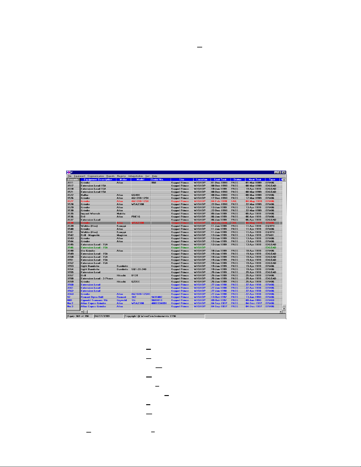
• Colour Code on main screen.
Black
Green
Red
Blue
Fig 1.
Any reference made to Windows™ is made in respect of Microsoft Corporations LTD Programs
1. INSTALLATION PROCEDURE OF WinPATS™.
2
Page 3

1. Start Windows™ running. Compatible with Windows™ 3.11. 95, 98, NT
2. Place the disk label “WinPAT Installation Disk 1” into the floppy drive on your
computer.
3. Open the File menu from Program Manager and choose the Run option from the
menu.
4. In the Run dialog box enter the command “A:\setup.exe” (or specify an alternative
drive if the setup disk is in another drive other than drive A:)
5. Follow the instructions prompted by the setup program.
Setup will by default place your program in a directory C:\WINPAT84K on the current
drive unless you have specified an alternative location. The first time WinPAT is run
an initialization file WINPAT.INI is created. You can find this file in the LOCAL
directory. The initialization file assumes that your program is installed to the
C:\WINPAT18K directory. If you have installed your program to a different drive or
directory then please modify the entry. You can edit Directory name by clicking on
Browse Button. Then either change names of directory or drive allocation.
2. OPENING THE PROGRAM
A Program group is set up in your system directory, or Programs file (win95, 98,NT)
click on Diamond icon to start program. The
Diamond Icon can be placed in your tool bar for
short cut running of the program.
A Title program box (Fig 2.) will appear in the
center of your screen, click on
database. This can be selected from the
Database
Select WinPATS™ Database box opens allowing the user to select a database from any
other disk drive or network drive.
3. LOGIN
This program is password protected. The first time the program runs it automatically
sets up an account for the first user as an administrator.
administrator should also set up user accounts for other people who will be using this
program. When opening database, enter user code and password. If OK Button is pressed,
selection or from the list below.
File
to select a
Open
Fig 3.
Fig 2.
A capital P is used for the
initial pass word and user code.
The pass word and user code
may be changed by the user at
any time in the Administration
menu under Users.
Having registered, the
3
Page 4
system will ‘boot up’ the selected database. The Open Database Menu is used for
selecting a database, using a standard Windows™ search facility.
The password is encrypted so only a star * shapes will appear on the screen when typed in.
4. THE MAIN PROCESSING SCREEN
After the program has confirmed the rightful user of an account, then the main processing
screen is loaded. This screen will remain visible throughout the operation of the program.
The details of all equipment in the registry are displayed on the Main grid screen. The
default order for the equipment records displayed in the Main grid screen are by Part
Number. The columns in the Main grid screen can be customised to your own preference.
You can move columns around to group certain information together. Simply place the
cursor on the heading of the required column then drag it to the left or right to the correct
position. Information displayed in the Main grid screen cannot be edited directly.
Fig 4.
5. Drop Down Menus.
File 5.1
Equipment 5.2
Communication 5.3
Reports 5.4
Registry 5.5
Administration 5.6
Sort 5.7
Help 5.8
5.1 File Menu -
4
Click on File Menu or Press Alt + F
Page 5

The following options appear:
5.1.a Close Database -
This function closes the current database open on the screen and takes you back to
the beginning of program, where you can exit completely from program or simply
select another database.
5.1.b. Copy Database -
This function simply allows the user to copy the current database to another disk
drive this is ideal for back up purposes and is recommended to backup each time
you have updated your database.
Click on Close Database or Press Alt + C
Click on Copy Database or Press Alt + y
5.1.c. Printer Set Up
This option allows you to setup parameters for your printer.
This is a standard Windows™ control panel for all your printer settings.
5.1.d.
This function allows the user to attach down loaded test results data (from pat
E.g. If you have downloaded all of your testers test results into a database, (Pat tester
5.1.e.
Append -
tester) that is held in an another database to currently open database.
having several sites of test results stored in its memory) and you need to update
some of the tests into your current database. Due to current database, having a
completely different site and equipment and the Pat tester had the test results for
this site down loaded into another database, you need to access these results to
update the current databases information.
You simply click on Append, search and select the database with the Down loaded
test results and proceed to update the test results as described in Update the
procedure.
Queries -
- Click on Printer or Press Alt + r
Click on Append or Press Alt +
Click on Queries or Press Alt + Q
A
This selection box
appears when Apply
button is selected.
This function allows the
user to set up search
fields and scenarios.
Giving the user
powerful methods of
searching, grouping and
reporting of equipment.
Double click on field
name to begin set up of
Fig 5.
The selection Button now becomes highlighted allowing the user to select it to set selection
criteria.
user criteria.
5
Page 6
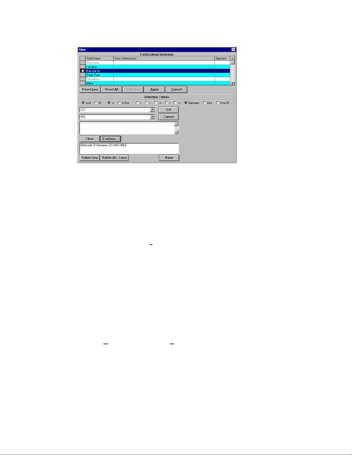
This Figure displays all
options for search
selection. Not all fields
are displayed at all
times. Only the
necessary fields are
displayed depending on
which Field name is
Fig 6.
selected or expression
requirements.
NOTE: read the Boolean expression as a sentence this will assist in understanding how
your search will work.
Search procedure examples.
1. If you wish to select only one Site Name (or Location, Description, Make,
Model, Bar code or any of the items shown in the list) simply Double click on
the line Site Name. This will highlight the line in dark Blue; the select button is
now active. Click on Selection button. The bottom selection boxes will now
appear.
a. To Simply, select the Site Name from List.
b. Clicked on the DROP DOWN arrow next to the SET button. (The program
is text sensitive which allows you to begin typing the name of the site and it
will appear allowing you to stop typing and click speeding up the selection
process.)
c. Scroll down if you have to and double Click on the required name.
d. When the required Site Name is shown in the selection box next to the drop
down arrow you have just clicked on, click on the SET button.
e. If that is the only site, you wish to select then press the DONE button below.
f. The Selection criteria will disappear and all you need do now is Click on the
Apply Button. When the Apply button is pressed the computer will then go
in search for the selected Site Name and all its Items and display them on the
screen.
2. If you wish to make a more complex, search or multiple searches for several
sites or locations please follow the following.
a. Repeat steps 1.a. to 1.d.
b. To continue adding site name to the list once you have clicked on SET
button click on the CONTINUE Button. This will move your selection to
the next Box and allow to repeat Steps 1.a to 1.d.
6
Page 7
c. Note that the AND / OR box now appears so please select required state.
d. You can repeat the above steps for as many sites you require.
e. If you have selected the wrong Site or changed your mind, you can click on
CLEAR button before Continuing to the next stage.
f. If you make a mistake simply highlight the line, you wish to delete from
your equation and click on DELETE LINE Button.
g. If you wish to delete the equation Click on DELETE ALL LINES Button.
h. If you have completed your search requirement click on the DONE Button
and continue as above in 1.f.
3. Once you have selected your site(s) you can continue to enhance your search or
sorting by through Locations, Bar codes, and all the other fields you wish to
have specifically searched or sorted.
Very powerful and complex scenarios can be made which enhances your speed
for repeating the process next time, once you have saved the set up.
The Query is a great tool for printing reports in specific formats also.
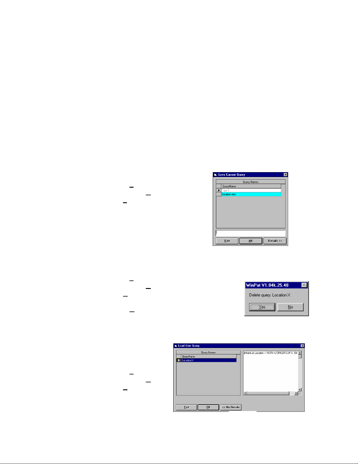
5.1.e.1. SAVE Query.
a. Click on File Menu
b. Scroll down to Queries
c. Select Save, Save current Query box
appears.
d. Type in Query name in text box
below.
e. Click on OK button to accept.
f. Click on Exit Button to cancel and not
save Query.
g. Details>> Button shows the whole query expression.
5.1.e.2. DELETE Query
a. Click on File Menu
b. Scroll down to Queries
c. Select Delete, Delete user Query box appears.
d. Click on query you wish to delete.
e. Click on Yes button to accept.
f. Click on Exit Button to cancel and not delete
Query.
g. A confirmation box will give a second chance.
5.1.e.3. LOAD Query
a. Click on File Menu
b. Scroll down to Queries
c. Select Load, Load user
Query box appears.
d. Click on the query you
wish to use.
e. You can check details
of your query by
Fig 7.
Fig 8.
Fig 9.
7
Page 8

clicking on DETAILS>> Button and the box will display query format.
f. Click on OK button to accept. Query will be activated and information from
query shown on main screen
g. Click on Exit Button to cancel and not use any Query.
5.1.e.4. SHOW CURRENT
This Box displays the active query if there is one active. If not active box is,
blank.
5.1.f.5. SHOW ALL RECORDS
This cancels any active Query and resets the screen to view all data in database.
5.2. DEFUALT GRID LAYOUT
You can move the columns where you like into any order and make them as wide or
To move a column just click, drag on the header bar, and let go when it’s where you
To expand or Narrow the column Place mouse pointer on vertical line that separates
This Function resets the Main grid screen to original settings.
narrow as you like. Even to the point of closing them completely. If this happens
and you want to see the entire data again just click on DEFAULT GRID
LAYOUT, Button and the database layout will return to normal default.
want it.
the columns in the header bar and a horizontal double arrow will appear click and
drag to desired position and release button. It should then stay in that position, even
when you comeback next time into the program.
Exit
- Click on Exit or Press Alt + x
This option exits the Database, taking you back to the selection screen. From
this screen you can select an alternative database or Exit completely.
8
Page 9
6.1.
6.0 The Equipment Menu
Equipment Menu -
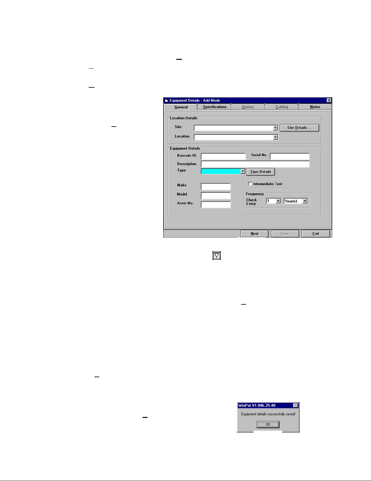
ADD
The following box
appears, (fig 10.) here
the operator can enter all
the new Add click on
add or Alt + A
equipment details. The
design enables data entry
to happen quickly and
create a database. The
data entry person need
not move out of this page
until all equipment data
is entered and ready for
the download loaded
information from the
tester needs updating.
Begin entering details by
simply selecting Site
from site list displayed
from the drop down box double click on required site. The site name will
move into top box.
Do the same for Location.
If you need to create, new Sites and locations click Site Details Button. (For more
details See REGISTRY MENU Section 10.1) for starting a new database.
If establishing a new database or adding new items in sequential order enter the first
Barcode number. Enter the other details as required Description, Select Type code
from list. Enter Make, Model & Asset Number if required.
Set test frequency this defaults to 1 year but manual over ride is possible by typing
in or selecting the default numbers and then selecting Week, Month or Year.
If NEXT Button is pressed, the information typed into the fields remains the same.
The Barcode ID increments one number and the serial number box becomes empty
ready for new number. This is set up this way so if you are entering batches of
identical items you can create many new items in a very short time.
Caution must be used because you will create a new
item every time the NEXT Button is pressed. This
box appears to confirm entry.
If you wish to type in new details simply click on
required box or move the cursor using TAB key.
Click on Equipment Menu or Press Alt + E
Fig 10.
Fig 11.
9
Page 10

The Items will become highlighted enabling the data entry to begin immediately
without having to clear the field.
The SAVE Button is only activated when information has been entered into a Data
field.
The SAVE Function saves only the current information displayed on the screen and
you need to press the EXIT button to get back to main Screen.
6.2.
MODIFY
You can add new equipment by clicking on the Add button in the Equipment
Menu. You can view and edit existing equipment detail (fig 10) when you double
click on the row/item highlighted or click on the Modify button in the Equipment
Menu.
You then enter the Equipment Details – EDIT MODE screen.
After you have edited the details, you will return to the equipment details screen to
the same row/item you have edited.
6.3. DELETE
To delete an equipment record,
first select the item/record you
want to delete, then by clicking on
the appropriate row/Item. This
action will highlight the row of
your selection, then click on the
Delete button in the Equipment
Menu and you will have a
message box (Fig 11) to confirm
the deletion. If you
click on the OK
Button the
equipment will be
equipment grid will refresh.
Once you have deleted an equipment record,
there is no way of recovering it!
Click on Cancel Button if you do not want to Proceed.
6.4. Equipment Details Screen
The operator can make changes or add the appropriate details in the fields on the
screen (Fig10). When you press the Save Button the details entered or changed are
saved. When there are a number of options the operator can select from, a
dropdown list box appears. The operator simply selects the appropriate
option by clicking with the mouse. The selected item will now appear in
the top of the box. The Equipment Details Screen information is grouped into 4
sections:
Fig 13
Fig 12
deleted along with any history
records attached to it and the
10
Page 11

6.4.a. General: (Fig10) Where the following information is contained, Site,
Location, Part number, Serial number, Description, Equipment type, Make, Model,
Issue number, Frequency, Unit e.g. Week(s), Month(s), Years(s).
6.4.b. Specifications: (Fig 12) Where the following information is contained, Protection
Fuse Type, Max Loading, Phase, kVA and Short circuit.
SPECIFICATION TAB - Click on to Select
This form allows the user to enter more
specific electrical details, of the current item
being entered if required.
A list of protective device can be selected from
the FUSE DETAILS Button.
Additional types can be created via the
Register Menu.
Fig 14
6.4.c. History: HISTORY TAB - Click on to Select
Contains the following information:
General Details: Last test date,
Next test date and Last result
status.
This form enables the user to view
previous test history and data. By
clicking on the test result line the
corresponding test results are
shown complete with Status, Date
tested, Next test due, Tester Serial
Number and usercode.
These are the test results
downloaded from the Tester via
Fig 15.
the Down load grid in the GET
From Pat Menu. Test Notes can be entered via the test result page prior to
updating. These notes are specific to that particular test and time. A repair or other
comment may be mentioned here.
Equipment Tests Completed Grid: Equipment Type, Test date, Test
number, Test result, Intermediate test flag, No register flag, Pats unit type
and Notes.
Test Details Grid: Pat Serial Number, User code, Test type, Test units, Test
value, Upper limit parameter, Lower limit parameter, Test result.
11
Page 12

For every row (record) displayed in the Equipment Tests Completed grid,
there are a series of test details contained in the Test Details grid. The user
must highlight (click) on a row in the Equipment Tests Completed grid and
the Test Details are displayed automatically. You can only view information
in this screen.
ADD TEST Button allows the user to enter test results manually.
If you wish to add a manual test click on the Add Test button this will enter you into a
screen where the program will expect to receive information similar to what is contained
on this screen. Click the row of test
performed in the Results column, Type or
select P = Pass, S = Skip, F = Fail test
performed.
Fig 16.
Select (fig 13)
This form allows the user to enter any
general notes about the equipment, Up to
255 characters allowed in this field.
Cabling Tab Disabled not used.
6.3.d Notes: NOTES TAB – Click on to
Fig 17.
7.0 Communication Menu
12
Communication Menu -
Click on Communication Menu or Press Alt + m
Page 13

The following options appear:
7.1 Port Settings (or press Alt + P)
7.2 Get from Pat (or press Alt + G)
7.3 Wand Input (if Option Fitted)
7.4 Setup Unit (if option fitted)
Down Load Procedure.
To begin Down loading from Seaward Pat tester the following procedure can be used.
• Select Communication Menu
• Select Port Settings (or press Alt + P) ensure setting are correct and
proper model selected in menu then save. See Fig 15 & section 7.1. For
Details.
• Select Get From Pat in the Communications Menu as screen like fig
20 will be displayed.
• Type in PAT serial Number (serial Number found on Tester unit.)
• Select Number of Characters this is very important. See Section 7.2.R
for details.
• Select Method Box Clear or Append. See Section 7.2.Q Fig 17 & 18.
• Click Down Load Button
• Click on APPEND / CLEAR OK Button
A green box will appear with WAITING in it.
• Select Pat tester DATA SEND Button and Follow instructions.
Numbers will begin to scroll in Green box.
• If not a communications error may exist (check settings)
If WAITING stays in box the system will time out Don’t Panic Wait for Fig
21 to appear before proceeding.
Please leave computer alone whilst downloading as interfering could cause
data corruption.
When all data is down loaded a
end of transmission box will
appear, Press OK button the
computer will verify results and
begin to display them on the
screen. Please Leave computer
alone whilst doing this. Wait for
Data download complete button
to appear. This completes the
down load process.
• Now you must carry out
UPDATE procedure see
Fig 18.
7.1 Port Settings -
Click on Port Settings or Press Alt + P
Section 7.2.U.
This option allows you to enter the port setting screen. In this screen, you set the Port,
Baud Rate and Pats Unit Type.
PLEASE LEAVE AS DEFAULT. Data Bits 8, Parity (none), Stop Bits 1.
Default Settings for Pat 1000 Baud Rate 1200,
13
Page 14

Default Settings for Pat 2000I Baud Rate 9600,
Port settings will depend on your computer.
An error box will usually appear if there is a conflict with an other device.
Wand & BHT 5000 are options and will only appear if you have ordered these
options.
SAVE settings, this allows for by passing the above procedure next time you plug in
your tester.
7.2 Get From Pat -
Click on Get From Pat or Press Alt + G
This function allows you to enter the DOWN LOAD screen. Here is where
connecting to the testing units is seen. Down loading of test, results and entering of
new equipment can be entered here.
Fig 19.
The down load Grid: This grid contains the following information about every test
The sequence no: Sequence number of test. This is simply a counter used by this
UD flag Record Updated flag. This flag is used when the current record has been
Test No. Test number from the Pats Unit. These numbers are automatically generated
14
This screen has the following features:
downloaded from the Pats tester Unit.
program for range updating.
through the update process.
by the Pats Unit.
Page 15

NRNo register flag. This flag is used by the operator when user wants the current test
recorded to the history but does not want to show in any reports or to affect
other data because of processing.
Int (test flag)Intermediate test flag. This flag signifies that the current test is
an intermediate test i.e. a test done before the due date, however record in
the history details and does not affect any other data because of processing.
Test Date. Test date from the Pats Unit.
PartNo. Part number as inputted to the Pats Unit from the operator. This is
modifiable to the user.
Result 1-18. Results as recorded by the Pats Unit
Status 1-18. Status’s as recorded by the Pats Unit for every Result
Result. Overall result status. This is a computer generated result status.
Notes. As inputted by the operator of the Pats Unit at time of test.
Test Mode. Can be MANual or TEST or AUTO, as set by the operator of the Pats Unit at
time of testing.
User Code. User Identification number, as set by the operator at time of testing.
Pat Serial No. The Serial number from the TESTER is required by the program to maintain
traceability of test results.
Site Name. Is required by the program to do Updating. Select from the dropdown list.
Update Seq. No. This option allows the user to nominate a range of tests to be
updated. This is useful when tests have been done across a number of sites.
The user wishes to nominate say tests 1-25 to be updated for one particular
site he enters 1 in the From box to 25 in the To box, then proceeds to select
the site where the items belongs. Click update and the Items 1 to25 will be
checked of and if found in that site. If tests 26 –30 belong to another site
then replace the from/to numbers to SEQ 26-30 select the new site and
continue as above. Do this until all records are updated and then it is safe to
clear test result grid.
Method:
Clear: This option clears the down load grid before a
new down load occurs.
NOTE: make sure you have updated all the test
results before CLEARING. To check this a tick
must be in the UPD box
Append: This option appends new down loaded data, to the current data in the down
load grid, when a new down load occurs.
It is recommended that you clear this regularly as
it will just become huge and difficult to
manipulate.
No Chars of PNO:
This option allows the user to nominate how may characters the Part number
is to be padded out when down loading from the Pats Unit. E.g. if 6 then if
a part number inputted by the operator of the Pats Units is say 101 then the
program will convert 101 to 000101. Therefore 101 is a different number
than 000101.
This is a critical issue and must be understood selecting the No.Chars can
make a difference in whether you need to down load again or not.
Fig 20.
Fig 21.
15
Page 16

DEFAULT option
Clicking this option will down load the numbers from the PAT tester with
only the numbers starting at the digit. These numbers can be from one digit
to 10 digits long all prefixed zeros are ignored.
Command Buttons:
Down Load: When this button is clicked the program prepares for down load from the
Pats Unit.
Update: This button is clicked when the user wishes to update the test results in the
down load grid to the Main Database Grid. The update procedure detects
whether a part number exists or not. If the part number is not found in the
particular site nominated in the database, the program prompts the user to
add in the new equipment. The user has the option of going through the
update process or skipping the current test, perhaps to be done later. When
the user goes through the update processing then the UD (update flag) is
ticked otherwise it is not.
Exit. Exits the down load screen. If there are any records which have not been
ticked in the UD column a
warning message appears.
(Fig 19)
It is safe to exit as all your down
loaded results are saved in the
down load grid which can be
Fig 22.
updated at any time.
Record Summary Information:
Total received - Total amount of tests down loaded for Pats Tester.
Records Updated - Number of updated tests in viewed down load grid table.
New Equipment - Counts new entries
Remaining - Number of units waiting updating to main database.
Status - Waiting - able to accept data from Pats Unit
- Receiving - receiving data from Pats Unit
- Verifying - verifying down loaded data
- Processing - adding down load data to the
grid.
Fig 23.
16
Page 17

8.0 Reports
Reports -
The following options appear:
Click on Reports Menu or Press Alt +R
8.1 Print Reports -
Click on Print Reports or Press Alt + P
See The Report Screens for further details.
This option enters you into the reporting module. Here you can
select and print preformatted reports or have the ability to customise
some standard reports.
8.2 Compliance -
Either a single appliance or a entire site or specific groups.
Click on Compliance or Press Alt + C
This option allows you to print a compliance certificate for
8.1 Print Reports Explained
Click on Print Reports for Report: Step 1
Clicking on Fixed option will generate a report with all the standard datafields that
are displayed on Main screen Grid.
Fig 24.
Click on Exit to return to main screen.
Clicking on the the Custom option allows the user to select their report format and
details. Click on the Field Selection List select the field you wish to have on your
report, you can double click on the field or click once and then on the ADD Button
to move field across. The user can click on the >> Button and all the fields will
move.
The << Button will move all selected fields in the right hand column back to the
Left selection field list. To Remove just one item in the right hand column click on
Click on Custom for
Report Step 2.
This allows you to select
fields required in the
final report. Highlight
field required and click
on ‘Add’ button. This
will display fields to be
reported on, in the right
hand display box.
17
Page 18

it to highlight it and then click on Remove Button, or simply double click on field
you wish to remove.
Primary Sort
allows the user
to do a create a
sort order on
how you wish
to display your
data.
Primary Sort
on any of the
selected fields.
Click on, and
highlight
Fig 25.
required field
for selection.
As described in Field Selection. The Chosen field(s) will be sorted in alphabetical
or numerical order depending on field type. You don’t need to select all fields. If
you only want to priorities using one field that’s ok, just select one field by double
click or select and Add.
Click on Back to return 1 Step .
Click on Next to continue to Report Step 3. (fig 26) This allows you to name the report,
Fig 26.
click on Report Heading box, and type in desired report name.
18
Page 19

Click on Print Preview to view report layout. Click on close to return to step 4.See
Click on Print Setup to change printer defaults. Standard Windows™ Printer setup
configuration. Printer Defaults to General printer used by other programs.
Report Step 4. Click on Print will print report via default printer.
Fig 27.
If you wish to change layout Click on Close Button. If lay out OK Press Printer Icon
Forward and Backward Arrows allows you scroll through your print preview.
The Icon with three squares is the ZOOM button.
The Brief case Icon allows you export data (see Fig 28)
The Envelope & Paper Clip Icon sets up the Data for Electronic Mailing. Save to disk
send via E-Mail etc. Select Number and Date format as shown in (Fig 28.a.) and follow
your default E-mail program once you have pressed OK Button.
Fig 28.
Fig 28.a.
19
Page 20

Fig 29.
Fig 29.
Fig 30.
20
Page 21

8.2 Compliance Report Explained
Click on Compliance or Press Alt + C (Fig 29) Appears.
View last Certificate printed.
Click on this to view the last certificate. This function allows you reprint
your previous report incase you need duplicates.
Place the Details required in the appropriate fields, you can select Site and
Locations from drop down box or Star * to select all sites. The star * will
take the whole database and compile a report on the whole database.
If you wish only to print a report on an individual item select the Barcode ID
from the list. By doing this, this will set the report just to print the
information on that particular item. This is handy for acceptance testing etc.
The Test Date From/To allows the user to select specific times that the
report can be printed for. This can be used for submission of summary to
show work done or required doing.
Date Printed the user can select the date of the report being printed. Use the
up/down arrows to change. The date in box will always default to your
current date set by the computer.
The user can enter more specific details of where the work was done or
printed by filling in the Site field and Phone Number.
Or Details about the appliance in the Appliance Field. See Fig 30 for sample
report.
8.3 Modify Certificate Text
This Button allows the user to enter his own wording to be shown on the
report. Not all fields are editable (Mainly Title Fields) but those, which are
relevant to comment, are. Once you have edited your text Click on Update
Button to save your new wording.
The Default Button will always bring you back to how the program was
supplied.
9.0 THE REGISTRY.
21
Page 22

Registry -
The following options appear:
Click on Registry Menu or Press Alt + g
Sites/Locations Equipment Types -
Fuse Types Test Types -
The Registry in further detail.
Click on Fuse Type or Press Alt + F
Click on Test Types or Press Alt + T
The registry option from the main menu allows you to manipulate type data in the
registry such as Equipment Type, Sites/Locations and Fuse Protection Type.
Click on Sites/Locations or Press Alt + S
Click on Equipment Types or Press Alt + E
Fig 31.
From the registry you can add, delete and edit details about types.
These options enter you into the editing of the selected registry. You will see a grid
where you can add, edit or delete records. If you add or edit details, you will then
enter a preformatted screen, which will display details related to the selected record.
The Save button will save the details you have added/edited. The Cancel button
will leave everything as it was.
To select a record, highlight a row on the grid, and then click on Select or double
click on the row to continue to edit details. Note - Site code is numeric only and
cannot be changed once entered.
Click on New to enter all new record details. All codes are user definable.
Click on Delete to delete a record Click on Exit to return to main screen.
Fig 32.
22
Page 23

10.0 SORT
SORT - Click on Sort Menu or Press Alt + S
There are nine different sort functions, which act on the ALL the records in the database.
1. Barcode ID only.
2. Barcode ID within Site.
3. Barcode ID within Location within Site.
4. Barcode ID within Test Date.
5. Test Date within Site.
6. Test Date within Location within Site.
7. Barcode ID within Due Date.
8. Due Date within Site.
9. BarcDue Date within Location within Site.
Sort Menu explained.
1. Barcode ID; Sorts the whole database or Query selected screen in barcode order
only from smallest number too largest. Including alphanumeric codes take priority
over the plain numeric codes.
2. Site, Barcode ID; Sorts the whole database or Query selected screen with
priority to Sites starting from A, then the Barcode Ids within those sites in Alphanumeric and Numeric order as described above.
3. Site, Location Barcode ID: Sorts the whole database, (or Query selected) screen
with priority to Sites starting from A. Then Locations (which can be Alpha-numeric
codes) starting with A. Then Barcode Ids within those sites in Alpha-numeric and
Numeric order as described above
4. Test Date, Barcode ID; Sorts the whole database or Query selected screen
with priority to most out of date test date. Then Barcode Ids within the in
Alphanumeric and Numeric order as described above.
5. Site, Test Date; Sorts the whole data base or Query selected screen with
priority to Site starting from A, then to most out of date test date.
6. Site, Location, Test Date; Sorts the whole database or Query selected screen
with priority to Sites starting from A, then Locations (which can be Alphanumeric
codes) starting with A. Then to most out of date, test date.
7. Due Date, Barcode ID; Sorts the whole database or Query selected screen
with priority to most out of date Due date. Then Barcode Ids within the in
Alphanumeric and Numeric order as described above.
8. Site, Due Date; Sorts the whole data base or Query selected screen with
priority to Site starting from A, then to most out of date Due date.
23
Page 24

9. Site, Location, Due Date; Sorts the whole database or Query selected screen
with priority to Sites starting from A, then Locations (which can be Alphanumeric
codes) starting with A. Then to most out of date Due date.
11.0 ADMINISTRATION
USER SELECTION PROFILE SCREEN.
11.1 Administration -
The following options will appear:
Click on Administration Menu or Press Alt + A
Users -
The Administration/User screen for further details.
This option enters you into editing users on the WinPAT™ system. You can
change passwords; add/edit/delete users from the system and setup access levels.
NOTE: Access to Administration Menu in not available to Users with a
User level other than 1. The Title Administration is not visible on the menu bar on
levels other than one.
This screen shows who is setup on the system and all relevant details.
Click on Users option or Press Alt + U
Fig 33.
User Details
Name - This Table shows the user all current users on system highlight to
select.
User Name - selected code/name created by the user
Qualification - displays qualification of user that is highlighted.
24
Page 25

Access Profile - user level is selected by Administrator (who is a level
1user). Level 2 & 3 accessibility is selected by the Administrator.
Notes - use for general notes as needed
New User - click to view
New User Account. Add
details and the click to
Save or click to Cancel
Buttons.
Delete User - click to
delete current user. Click
OK or Cancel Buttons
(see above Fig 33)A
confirmation box will
appear to make sure that
you are sure.
Fig 34.
Access Level - click to
view Access level settings. Click Access level dropdown list; highlight access
functionality to user level.
Example - select ‘2’ then click on ‘File’, click to mark with an X which function
you will allow access to in file menu. Continue with all functions. Click SAVE
Button to register these as default Access levels for level 2 and return to previous
page. Click Exit to return to previous page without saving.
Edit Details - click to view and edit any current user details.
New Password - click on New Password (Fig 35) to change password or enter
new password. Type in new password; note that this is ‘Caps’ sensitive. Press tab
or click on Confirm Password, re-type password to
confirm, then click on OK. Password confirmed
will appear, click on OK to continue. (*Note Remember your new Password! *)
Exit - click on Exit to return to the main screen.
Fig 35.
25
Page 26

11.2 Clear Database
SITES This is a very powerful command USE WITH UTMOST
CAUTION. Whole databases, Equipment Lists and Test results can be deleted
from this section. THIS NOT QUERY SENSITIVE.
Click OK
YOUR LAST CHANCE SO GET IT
RIGHT!!!!!!!
THE
DEFAULT IS ON
YES SO BE
CAREFUL
Clear All EQUIPMENT - This function Deletes the Equipment Register but
keeps the Client information only.
Click OK
YOUR LAST CHANCE SO GET IT
RIGHT!!!!!!!
THE DEFAULT IS ON YES SO BE CAREFUL
!!!!!!!!!!!
Clear ALL EQUIPMENT TESTS. – This Function deletes any test records
that have been attached to any of the equipment. Clears all test history.
THE
DEFAULT IS ON YES SO BE CAREFUL
!!!!!!!!!!!
26
Page 27

11.4. Administration
Fix Part No.
Increase By 1= Adding on one complete column of 0 (zero) expanding your
number range if required due to growth of appliances numbered.
Decrease By 1 = Takes one complete column of digits from your
BARCODE ID numbers. E.g., number A12345 becomes 12345
This function can be used in groups when used in conjunction with a Query.
Select the group of Numbers you wish to change using a query then apply the Increase or
Decrease function.
12.0 Help
Recommend you use this Manual for the Latest Information and
Accuracy.
Help -
Click on Help Menu or Press Alt + H
Contents -
Click on Contents or Press Alt + C
This option displays the contents of the help file.
Index -
Click on Index or Press Alt + I
This option displays the index of the help file.
Search For Help -
Click on Search or Press Alt + S
This option displays the windows help file.
Legend -
This option displays a screen, which explains what the different
colours mean on the equipment grid.
Click on Legend or Press Alt + L
27
Page 28

13. THE RCD SCREEN. (If Option Fitted)
This option is only visible via the EQUIPMENT TYPE Table. If you have bought
this, option an Equipment type RCD1P can be seen on the list.
This option allows the user to enter test results from their manual test methods
required for RCD devices. These tests include Trip times, Button tests, Half-Current
trip test etc.
Input to the RCD screen is done when the user clicks on the ADD TEST Button on
the HISTORY Tab of an Item with a type code prefixed with RCD**. When this
screen is displayed, the user has the option to enter new RCD test results. If the
user chooses to Edit Existing RCD records then the program searches for equipment
records with the prefix of RCD in the
equipment type field, starting from the
highlighted row on the Main Screen
grid. Then the program displays the
data on the screen the operator has the
opportunity to change and then save the
data.
The user can create other types of RCD
devices as discussed in creating new
types in the Registry Menu under
Equipment Types See section
NOTE; the Equipment Type must start
with a prefix RCD for this function to
work.
E.g. RCD10F = Fixed Switchboard
mounted RCD with 10mA trip current.
28
Page 29

Default Trip times can be programmed for PASS/FAIL for these specific units also.
E.g. Fig displays trip time, Upper limit at 40ms anything > 40ms will flag fail.
If the Wand option (Manual Entry Option) has also been purchased. The
operator can scan the Bar code on the RCD that will then call the Item directly onto
the screen enabling the operator to enter test results on the spot.
Command Buttons:
Next Part No: In Add Mode this button saves the current details and increments the
part number, test number and prepares the screen to receive data for
a new test. In Edit Mode this button saves the current details and
then searches for the next part number record from the Main Screen
to display the details on the screen.
Next Test: This button saves the current details and attempts to display the next
available test results. If none is found the program notifies the user
and prompts for using the next available test number ready for
adding a new test. This happens in either Add Mode or Edit Mode.
THE NOTES EDITING FACILITY.
The notes editing facility is available throughout the program and can be activated
on any screen in which there is a notes throughout the program and where available.
You can enter up to 255 characters for notes.
14.0 SCANNER/WAND input (option)
Fig 40
This facility is
added for
extended uses
such as stock
take inventory
control, hire
and loan
search and
general
maintenance.
29
Page 30

15. ERROR MESSAGES
As with “ALL” programs WinPAT is not 100% bug free. Error messages are
designed to be understandable to the programmer so if you encounter a program bug
and an error message appears on the screen report it immediately or write down
exactly what you see on the screen and please call us. If you see the program is not
working as expected again we would be pleased to hear from you. Than You for
your assistance in these matters Thank you.
For Further Support call WAVECOM INSTRUMENTS PTY LTD.
PHONE: 61 08 8331 8892
FAX: 61 08 8331 3648
EMAIL:
WEB PAGE:
winpats@wavecom.com.au
www.wavecom.com.au
30
 Loading...