

Page 1

WAVECOM Decoder
W74PC, W-PCI/e, W-CODE,
W-CLOUD Manual V9.1.0
by WAVECOM ELEKTRONIK AG
Page 2

PUBLISHED BY
WAVECOM ELEKTRONIK AG
Hammerstrasse 8
CH-8180 Buelach
Switzerland
Phone +41-44-872 70 60
Fax +41-44-872 70 66
Email: info@wavecom.ch
Internet: http://www.wavecom.ch
© by WAVECOM ELEKTRONIK AG. All rights reserved.
Reproduction in whole or in part in any form is prohibited without written consent of the copyright owner.
The publication of information in this document does not imply freedom from patent or other protective rights of
WAVECOM ELEKTRONIK AG or others.
All brand names in this document are trademarks or registered trademarks of their owners.
Specifications are subject to change without further notice.
Printed: Friday, August 11, 2017
Page 3

Contents
General Information 2
Welcome ..................................................................................................... 2
Revisions ..................................................................................................... 2
Recommended WAVECOM Products and Services .............................................. 9
Setup 11
W-PCI/W-PCIe ........................................................................................... 11
W74PC ...................................................................................................... 13
W-CODE .................................................................................................... 15
Software Uninstall....................................................................................... 19
W-BV BitView Tool ............................................................................. 9
W-Sat-email-Decoder ......................................................................... 9
W-PCI/W-PCIe Hardware Installation ................................................. 11
W-PCI/W-PCIe Software Installation .................................................. 13
W74PC Hardware Installation ............................................................ 13
W74PC Software Installation ............................................................. 15
Wavecom Hardware Decoder License ................................................. 15
W-CODE Hardware Installation .......................................................... 15
Software Installation W-CODE, W74PC, W-PCI and W-PCIe ................... 15
W-CODE Server Control.................................................................... 16
W-CODE Device Serial Number .......................................................... 16
W-CLOUD Networking ...................................................................... 17
W-CODE Licensing ........................................................................... 18
First start 21
W-CODE First Start ..................................................................................... 21
GUI ........................................................................................................... 22
Command Line Parameters .......................................................................... 23
Default Data and Program Folders (Paths) ..................................................... 23
Main Menu ................................................................................................. 25
File Menu ................................................................................................... 26
Media Player/Recorder ..................................................................... 27
HF-Modes Menu .......................................................................................... 32
VHF/UHF-DIR Menu .................................................................................... 34
VHF/UHF-SUB Menu .................................................................................... 35
Satellite Menu ............................................................................................ 36
FAX & Modems Menu ................................................................................... 37
Options Menu ............................................................................................. 38
Alphabet......................................................................................... 38
Auto Decrypt ................................................................................... 38
Bit Inversion Mask ........................................................................... 39
CRC Recognition .............................................................................. 39
CRC Table....................................................................................... 39
Clear Screen ................................................................................... 40
Code Statistics ................................................................................ 40
Cycle... .......................................................................................... 40
Error Indication ............................................................................... 40
FAX & Modems Settings.................................................................... 40
Frame Format… ............................................................................... 41
IAS ................................................................................................ 41
Letters/Figures... ............................................................................. 41
Message Type... .............................................................................. 41
WAVECOM Decoder W74PC, W-PCI/e, W-CODE, W-CLOUD Manual V9.1.0 Contents iii
Page 4

Modem Settings… ............................................................................ 43
MSI ............................................................................................... 43
Resync Mode ................................................................................... 43
Signal Polarity ................................................................................. 43
Symbol Definition ............................................................................ 43
SAT Settings… ................................................................................. 44
Toggle ............................................................................................ 45
Time Stamp... ................................................................................. 45
Demodulator Menu ..................................................................................... 46
Auto .............................................................................................. 46
Mode... .......................................................................................... 46
PB Center... .................................................................................... 48
PB Bandwidth... ............................................................................... 48
Center............................................................................................ 48
Shift... ........................................................................................... 48
Baudrate... ..................................................................................... 48
Polarity... ....................................................................................... 48
Offset... ......................................................................................... 48
Input... .......................................................................................... 49
Gain... ........................................................................................... 49
Favorites Menu ........................................................................................... 50
Open... .......................................................................................... 51
Save As... ....................................................................................... 51
Configuration Menu ..................................................................................... 51
W-CODE Device… ............................................................................ 52
Font... ............................................................................................ 53
Temp Files... ................................................................................... 53
Settings... ...................................................................................... 54
Receiver and Satellite Settings... ....................................................... 54
License... ........................................................................................ 55
Custom Inputs... ............................................................................. 56
Custom Alphabets… ......................................................................... 64
SR Fine Tuning ................................................................................ 65
SR Calibration ................................................................................. 65
View Menu ................................................................................................. 67
Window Menu............................................................................................. 67
Help Menu ................................................................................................. 67
Contents ........................................................................................ 68
WAVECOM on the Web ..................................................................... 68
About W-CODE ................................................................................ 68
Other GUI Elements .................................................................................... 68
Toolbar .......................................................................................... 68
WAVECOM Toolbar ........................................................................... 68
Level Indicator ................................................................................ 69
Spectrum Indicator .......................................................................... 69
Decoder Status Bar .......................................................................... 69
Demodulator Status Bar ................................................................... 70
SAT Frequency Tuning Bar ................................................................ 70
FFT/Sonagram Context Menu ............................................................ 72
Mode Selector ................................................................................. 73
Passband Filter Support .................................................................... 78
Analysis Tools 80
FFT ........................................................................................................... 80
FFT (HF, SUB, DIR and SAT) ............................................................. 81
Tuning FFT or Sonagram .................................................................. 81
FFT and Sonagram ...................................................................................... 83
Waterfall ................................................................................................... 83
Waterfall (HF, SUB, DIR and SAT) ..................................................... 84
Sonagram .................................................................................................. 84
Sonagram (HF, SUB, DIR and SAT) .................................................... 85
Oscilloscope ............................................................................................... 85
FSK Analysis .............................................................................................. 86
iv Contents WAVECOM Decoder W74PC, W-PCI/e, W-CODE, W-CLOUD Manual V9.1.0
Page 5

FSK Analysis Options ....................................................................... 87
FSK Code Check ......................................................................................... 88
FSK Code Check HF ......................................................................... 88
FSK Code Check DIR ........................................................................ 90
FSK Code Check SUB ....................................................................... 91
PSK Symbol Rate (HF, DIR, SUB and SAT) ..................................................... 93
PSK Phase Plane (HF, DIR, SUB and SAT) ...................................................... 94
PSK Code Check (HF, DIR and SUB) .............................................................. 96
MIL-STANAG Code Check ............................................................................. 97
MFSK Analysis ............................................................................................ 98
MFSK Code Check HF .................................................................................. 99
Autocorrelation ......................................................................................... 100
Bit Correlation .......................................................................................... 102
Bit Length Analysis ................................................................................... 104
SELCAL Analysis ....................................................................................... 106
Fundamentals of Radio Data Transmission 108
Telegraph Speed, Bit Rate, Baud Rate and Symbol Rate ................................ 109
Formatting and Source Coding ................................................................... 110
Encryption ............................................................................................... 112
Channel Coding ........................................................................................ 113
Equalization ............................................................................................. 114
Synchronization ........................................................................................ 114
Multiplexing and Multiple Access ................................................................. 115
Modulation ............................................................................................... 115
ASK (Amplitude Shift Keying) .......................................................... 116
FSK (Frequency Shift Keying) .......................................................... 116
PSK (Phase Shift Keying) ................................................................ 116
M-ary-FSK (MFSK), M-ary-PSK (MPSK) ............................................. 116
OFDM (Orthogonal Frequency Division Modulation) ............................ 116
Bandwidth-efficient Modulation ........................................................ 117
INDIRECT FM ................................................................................ 117
INDIRECT AM ................................................................................ 117
FAX ......................................................................................................... 117
FAX Transmission Sequence ............................................................ 117
Transmission Modes 118
ACARS .................................................................................................... 118
AIS ......................................................................................................... 120
ALE-400 .................................................................................................. 121
ALF-RDS .................................................................................................. 122
ALIS ....................................................................................................... 122
ALIS-2 .................................................................................................... 123
AMSAT-P3D ............................................................................................. 124
APCO-25 ................................................................................................. 124
ARQ6-90 and ARQ6-98 .............................................................................. 125
ARQ-E ..................................................................................................... 125
ARQ-E3 ................................................................................................... 126
ARQ-M2-342 and ARQ-M2-242 ................................................................... 127
ARQ-M4-342 and ARQ-M4-242 ................................................................... 127
ARQ-N ..................................................................................................... 128
ASCII ...................................................................................................... 128
ATIS ....................................................................................................... 129
AUM-13 ................................................................................................... 130
AUTOSPEC ............................................................................................... 130
BAUDOT .................................................................................................. 131
BIIS ........................................................................................................ 132
BR-6028 .................................................................................................. 135
BULG-ASCII ............................................................................................. 136
CCIR ....................................................................................................... 137
CCITT ..................................................................................................... 138
CHINESE 4+4 .......................................................................................... 139
WAVECOM Decoder W74PC, W-PCI/e, W-CODE, W-CLOUD Manual V9.1.0 Contents v
Page 6

CHU ........................................................................................................ 139
CIS-11 .................................................................................................... 140
CIS-12 .................................................................................................... 141
CIS-14 .................................................................................................... 141
CIS-36 .................................................................................................... 141
CIS-36-50 ............................................................................................... 142
CIS-50-50 ............................................................................................... 143
CLOVER-2 ................................................................................................ 143
CLOVER-2000 .......................................................................................... 144
CLOVER-2500 .......................................................................................... 145
CODAN-SELCAL ........................................................................................ 145
CODAN-3212 ........................................................................................... 145
CODAN-9001 ........................................................................................... 147
COQUELET-13 .......................................................................................... 151
COQUELET-8 ............................................................................................ 152
COQUELET-80 .......................................................................................... 153
CTCSS ..................................................................................................... 154
CV-786 .................................................................................................... 155
CW-MORSE .............................................................................................. 155
DCS SELCAL ............................................................................................ 156
Demodulated Bitstream Output .................................................................. 157
DGPS ...................................................................................................... 158
DMR ........................................................................................................ 159
dPMR ...................................................................................................... 160
DTMF ...................................................................................................... 161
DUP-ARQ ................................................................................................. 162
DUP-ARQ-2 .............................................................................................. 163
DUP-FEC-2............................................................................................... 163
DZVEI ..................................................................................................... 164
EEA ......................................................................................................... 165
EFR ......................................................................................................... 165
EIA ......................................................................................................... 166
ERMES .................................................................................................... 167
EURO ...................................................................................................... 169
FEC-A...................................................................................................... 169
FELDHELL ................................................................................................ 170
FLEX ....................................................................................................... 171
FM-HELL .................................................................................................. 171
FMS-BOS ................................................................................................. 172
GMDSS/DSC-HF ....................................................................................... 174
GMDSS/DSC-VHF ..................................................................................... 174
GOLAY/GSC ............................................................................................. 175
G-TOR ..................................................................................................... 176
GW-FSK .................................................................................................. 177
GW-OFDM................................................................................................ 177
GW-OFDM-Modulation and Protocol .................................................. 178
Decoder ....................................................................................... 178
GW-PSK .................................................................................................. 179
HC-ARQ ................................................................................................... 179
HF-ACARS ............................................................................................... 180
HNG-FEC ................................................................................................. 181
ICAO SELCAL ........................................................................................... 182
LINK-11 (CLEW) ....................................................................................... 183
MD-674 ASYNC ........................................................................................ 184
METEOSAT ............................................................................................... 184
MFSK-20 ................................................................................................. 185
MFSK-8 and MFSK-16................................................................................ 186
MIL-188-110-16Tone, (MIL-188-110A/B Appendix B) .................................... 186
MIL-188-110-39Tone, (MIL-188-110A/B Appendix C) .................................... 187
MIL-188-110A .......................................................................................... 188
MIL-188-110A-MOD .................................................................................. 190
MIL-188-110B (Appendix C), STANAG 4539 ................................................. 191
MIL-188-141A .......................................................................................... 193
MIL-188-141B (Appendix C) ....................................................................... 194
vi Contents WAVECOM Decoder W74PC, W-PCI/e, W-CODE, W-CLOUD Manual V9.1.0
Page 7

MIL-M-55529A NB/WB .............................................................................. 195
MOBITEX-1200 ......................................................................................... 196
MOBITEX-8000 ......................................................................................... 197
MODAT .................................................................................................... 197
Fax & MODEMS Half-Duplex ....................................................................... 198
FAX-G3-V.17 ................................................................................. 198
FAX-G3-V.27ter ............................................................................. 198
FAX-G3-V.29 ................................................................................. 199
FAX-G3-V34hdx ............................................................................ 199
V.21, BELL103 .............................................................................. 199
V.22 / V.22bis, BELL212A ............................................................... 199
V.23 ............................................................................................ 199
FAX & MODEMS Full-Duplex ....................................................................... 200
V.26 / V.26bis ............................................................................... 200
V.32 / V.32bis ............................................................................... 200
V.34 ............................................................................................ 200
V.90 ............................................................................................ 200
V.92 ............................................................................................ 201
MPT-1327 ................................................................................................ 201
NATEL ..................................................................................................... 203
NMT-450 ................................................................................................. 204
NOAA-GEOSAT ......................................................................................... 204
NWR-SAME .............................................................................................. 205
NXDN ...................................................................................................... 209
OLIVIA .................................................................................................... 209
ORBCOMM ............................................................................................... 210
PACKET-1200 ........................................................................................... 211
PACKET-300 ............................................................................................ 212
PACKET-9600 ........................................................................................... 213
PACTOR ................................................................................................... 213
PACTOR-FEC ............................................................................................ 214
PACTOR-II ............................................................................................... 215
PACTOR-II-AUTO ...................................................................................... 216
PACTOR-II-FEC ........................................................................................ 216
PACTOR-III .............................................................................................. 217
PACTOR-4 ................................................................................................ 219
PCCIR ..................................................................................................... 219
PDZVEI ................................................................................................... 220
PICCOLO-MK6 and PICCOLO-MK12 ............................................................. 221
POCSAG .................................................................................................. 222
POL-ARQ ................................................................................................. 224
PRESS-FAX .............................................................................................. 224
PSK-10 .................................................................................................... 225
PSK-31, PSK-63, PSK-125, PSK-250 ........................................................... 225
PSK-31-FEC ............................................................................................. 226
PSK-63F, PSK-125F, PSK-220F ................................................................... 227
PSK-AM ................................................................................................... 228
PZVEI ...................................................................................................... 228
ROBUST-PACKET ...................................................................................... 229
RUM-FEC ................................................................................................. 230
SAT-AERO-P, SAT-AERO-R, SAT-AERO-T ..................................................... 231
SAT-AERO-C ............................................................................................ 231
SAT-B ..................................................................................................... 232
SAT-B-C-TFC ............................................................................................ 232
SAT-B-C-HSD ........................................................................................... 233
SAT-C-TDM, SAT-C-TDMA, SAT-C-EGC ........................................................ 234
SAT-C TDM ................................................................................... 234
SAT-C-TDMA ................................................................................. 235
SAT-C-TDM-EGC ............................................................................ 236
SAT-M ..................................................................................................... 238
SAT-MINI-M ............................................................................................. 238
SAT-MINI-M-C-HSD .................................................................................. 239
SI-ARQ .................................................................................................... 240
SI-AUTO .................................................................................................. 240
WAVECOM Decoder W74PC, W-PCI/e, W-CODE, W-CLOUD Manual V9.1.0 Contents vii
Page 8

SI-FEC .................................................................................................... 241
SITOR-ARQ .............................................................................................. 241
SITOR-AUTO ............................................................................................ 242
SITOR-FEC............................................................................................... 242
SP-14 ...................................................................................................... 242
SPREAD-11, SPREAD-21 and SPREAD-51 ..................................................... 244
SSTV ....................................................................................................... 244
STANAG-4285 .......................................................................................... 246
STANAG-4415 .......................................................................................... 248
STANAG-4481-FSK ................................................................................... 249
STANAG-4481-PSK ................................................................................... 250
STANAG-4529 .......................................................................................... 251
STANAG-4539 .......................................................................................... 253
STANAG-5065-FSK ................................................................................... 253
SWED-ARQ .............................................................................................. 253
TETRA ..................................................................................................... 254
Constraints ................................................................................... 257
TETRAPOL ................................................................................................ 258
THROB and THROBX ................................................................................. 262
TWINPLEX ............................................................................................... 262
VDEW ..................................................................................................... 264
VDL-M2 ................................................................................................... 264
VISEL ...................................................................................................... 265
WEATHER-FAX ......................................................................................... 266
X.25........................................................................................................ 266
ZVEI-1 .................................................................................................... 268
ZVEI-2 .................................................................................................... 268
ZVEI-3 .................................................................................................... 269
ZVEI-VDEW ............................................................................................. 270
Classifier (Optional) 273
Overview ................................................................................................. 273
Classifier ................................................................................................. 273
How the Classifier Works ................................................................ 273
Classifier User Interface ................................................................. 273
Caveats ........................................................................................ 278
Classifier Code Check HF (CCC) .................................................................. 278
How the Classifier Code Check Works ............................................... 278
User Interface ............................................................................... 280
Decoding ...................................................................................... 284
Classifier Code Check (CCC) VHF/UHF ......................................................... 284
How the Classifier Code Check Works ............................................... 284
User Interface ............................................................................... 286
Decoding ...................................................................................... 290
Classifier Code Check Editor ....................................................................... 290
Installation ................................................................................... 290
CCC Editor GUI.............................................................................. 291
Data Base Fields ............................................................................ 296
SAT System 298
Overview ................................................................................................. 298
Systems .................................................................................................. 299
RF Channels .................................................................................. 300
Logical Channels............................................................................ 300
MES Identification .......................................................................... 301
Session Signaling .......................................................................... 301
SAT Operation .......................................................................................... 301
Traffic-Channel Decoder ................................................................. 303
The Sat Aero System ................................................................................ 303
Services ....................................................................................... 303
Channel types ............................................................................... 304
Trouble Shooting ........................................................................... 305
viii Contents WAVECOM Decoder W74PC, W-PCI/e, W-CODE, W-CLOUD Manual V9.1.0
Page 9

Modem and FAX Modes 309
Overview ................................................................................................. 309
Line transmission .......................................................................... 309
Fax and Data Transmission ........................................................................ 310
Modem Functionality ...................................................................... 310
Handshaking ................................................................................. 311
Modulation Types .......................................................................... 312
Decoding ................................................................................................. 313
Input and interfacing ..................................................................... 315
Constraints ................................................................................... 315
Output ......................................................................................... 316
Additional Functions 317
License System, Software and Options ........................................................ 317
License System ............................................................................. 317
CmStick ....................................................................................... 317
WAVECOM Server ..................................................................................... 319
Introduction .................................................................................. 319
WAVECOM Server Control ............................................................... 320
Shortcut Manager ..................................................................................... 322
Adding a shortcut to an existing installation ...................................... 322
Alarm Monitor .......................................................................................... 323
Introduction .................................................................................. 323
Options ........................................................................................ 324
Settings ....................................................................................... 324
Run ............................................................................................. 326
Serial Link ............................................................................................... 326
Introduction .................................................................................. 326
Getting Started ............................................................................. 327
Status Information ........................................................................ 327
Remote Control ........................................................................................ 328
XML ........................................................................................................ 328
WAVECOM Data Formats 329
IP-CONF TCP/IP Data Format ..................................................................... 329
IP-PXGF TCP/IP Data Format ...................................................................... 329
OVERVIEW.................................................................................... 329
PXGF DESCRIPTION ....................................................................... 329
THE PXGF CHUNK STRUCTURE ........................................................ 329
APPLICATION NOTES ..................................................................... 330
DEFINITION OF CHUNKS ................................................................ 331
WAVECOM Data File Format ....................................................................... 333
File Header ................................................................................... 333
Data Structures ............................................................................. 334
File Headers and Data Structures for Individual File Types .................. 334
Appendix 342
Alphabets Details ...................................................................................... 342
Unicode ........................................................................................ 342
Questions & Answers................................................................................. 352
Signal Interference ................................................................................... 352
General ........................................................................................ 352
Antenna installation ....................................................................... 353
Receiver ....................................................................................... 353
HF cabling .................................................................................... 353
Grounding .................................................................................... 353
Location of decoder ....................................................................... 353
PCs and peripherals ....................................................................... 353
Video monitor ............................................................................... 353
LAN ............................................................................................. 353
Conditions of Sale ..................................................................................... 353
WAVECOM Decoder W74PC, W-PCI/e, W-CODE, W-CLOUD Manual V9.1.0 Contents ix
Page 10

General ........................................................................................ 353
Prices ........................................................................................... 354
Delivery time ................................................................................ 354
Dispatch ....................................................................................... 354
Return of goods ............................................................................. 354
Payment ....................................................................................... 354
Reservation of ownership ............................................................... 354
Cancellation .................................................................................. 354
Changes of order quantities ............................................................ 354
Legal domicile ............................................................................... 354
Warranty ...................................................................................... 355
Obligation ..................................................................................... 355
Copyright ..................................................................................... 355
Liability ........................................................................................ 355
Laws and regulations ..................................................................... 355
License Terms .......................................................................................... 355
Manufacturer Address ............................................................................... 356
Glossary of Terms 357
Index 367
x Contents WAVECOM Decoder W74PC, W-PCI/e, W-CODE, W-CLOUD Manual V9.1.0
Page 11

WAVECOM Decoder W74PC, W-PCI/e, W-CODE, W-CLOUD Manual V9.1.0 General Information 1
Page 12

Version
Date
Changes
Beta
20-Dec-2005
Initial draft.
6.3.00
15-Jan-2006
CMH files, index, installation.
6.4.00
15-Jul-2006
New protocols:
- PSK-AM
- MIL-188-110-16Tone
- CIS-12
- PACTOR-III
- CLOVER-2
- CLOVER-2000
- CODAN-9001
Improvements and modifications:
HF PSK CODE CHECK
HF MFSK CODE CHECK
HF CLASSIFIER CODE CHECK
Tuning FFT
Installation for PACTOR-III/CODAN/CLOVER Modes.
6.4.00
25-Aug-2006
W51PC added.
6.4.01
4-Oct-2006
W61LAN added.
6.4.02
4-Oct-2006
ServerControl.
General Information
Welcome
Thank you for choosing a WAVECOM decoder product. The product that you have purchased includes the
latest technology in data decoding, together with the latest software release available at the time of shipment.
Please check our website at http://www.wavecom.ch for software updates.
Before you install the product, please also check the latest documentation on the installation DVD or on
our website.
Wavecom Elektronik AG develops and sells products for wireless (HF/VHF/VHF/SHF) data monitoring in all
frequency bands.
Two decoder families are currently available:
W-PCI and W-PCIe are decoder hardwares with two physically independent channels.
W74PC is a hardware decoder with four physically independent channels. The decoder software WCODE supports all these three hardwares.
W-CODE works also as a stand-alone application with native host hardware, like the built-in
soundcard or other audio devices.
W61PC/W61LAN consists of hardware (e.g., W61PC, W61LAN) and corresponding, integral soft-
ware (no additional order of the software required).
Revisions
2 General Information WAVECOM Decoder W74PC, W-PCI/e, W-CODE, W-CLOUD Manual V9.1.0
Page 13

Version
Date
Changes
6.5.00
27-Apr-2007
New protocols:
- PACTOR-FEC
- CV-786
- MD-674
- MIL-M-55529a
- MOBITEX-1200
- VISEL
- STANAG-5066
Improvements and modifications:
Inputs added (streaming and user inputs)
Passband tuning added.
6.6.00
23-Jan-2008
New protocols:
- CHU
- DZVEI
- MIL-188-110-39Tone
- MOBITEX-1200
- MODAT
- NWR-SAME
- PCCIR
- PDZVEI
- PZVEI
- SAT-AERO (Aero-I)
- ZVEI-3
- Stanag-5065-FSK
Improvements and modifications:
W51PC removed
ATIS changed
New chapter: WAVECOM TCP/IP Data File Format
WiNRADiO Setup
Time cursors in sonagram
New manual layout.
6.6.5.0
2-Jul-2008
New protocols:
- OLIVIA
- BIIS-1200
Improvements and modifications:
Chapter: Professional version removed, as in the feature only one version is available
Phase plane “Sync/Async” replaced with “IQ demodulator”
"BITS" replaced by "BINARY" in ALF-RDS, CODAN 9001, INMARSAT-A, MIL188110A, -B, -16Tone, -39Tone, MIL 188-141B, STANAG 4285, -4415, -4529
"RAW" replaced by "HEX" in CIS36-50, CIS50-50,GW-FSK, GW-PSK, VISEL
STANAG4529 default center frequency changed to 1700 Hz
W-CODE added
WAVECOM Decoder W74PC, W-PCI/e, W-CODE, W-CLOUD Manual V9.1.0 General Information 3
Page 14

Version
Date
Changes
CodeMeter added.
6.6.60
22-Jan-2009
New protocols:
- SAT-B-C-TFC
- Robust Packet Radio
- ORBCOMM
Improvements and modifications:
User Manual split into a W-CODE and W-61 Manual
FAX and Modem added
SAT-AERO improved
User defined alphabets added
Sample Rate Fine tuning added.
6.6.70
14-Mai-2009
New protocols:
- FAX-G3-V.17
- FAX-G3-V.27ter
- FAX-G3-V.29
- FAX-G3-V34hdx
- V.21, BELL103
- V.22 / V.22bis, BELL212A
- V.23
- V.26 / V.26bis
- V.32 / V.32bis
- V.34
- V.90
- V.92
- ALE-400 added
- Alternative Modes for CODAN-9001 (W-CODAN-9001), CLOVER-2 (WCLOVER-2) and CLOVER-2000 (W-CLOVER-2000).
Improvements and modifications:
“Modems” modes added (incl. new “Modem Settings...” and “Modem Input File…”
options):
OSI-Level removed
MIL-STD … tuning changed
OLIVIA changed
PACTOR-II: AFC ± 50 Hz, additional frame type detection, HEX (Binary output)
Sonagram added to FFT tuning window
FFT and Sonagram tuning parameter moved from options to the new context menu.
“Pause Graphic” option for the sonagram tuning view
Passband display shows additional tuning information (shift mark, space frequency)
in a tooltip box, if the mouse is move over the cursors
Number of “Custom Alphabets” and “Custom Inputs” limited to 16
“Message Type” dialog box. New parameter for Parity (MARK and SPACE)
“Message Type” dialog box. Display format “ ITA5” and “ASCII” merged to “ITA5
4 General Information WAVECOM Decoder W74PC, W-PCI/e, W-CODE, W-CLOUD Manual V9.1.0
Page 15

Version
Date
Changes
(ASCII)”
WAVECOM Data File Format, additional information added
Added: List of checked modes with FSK Code Check
Name of ROBUST-PACKET-RADIO changed to ROBUST-PACKET
Changed license manager.
6.8.00
15-Nov-2009
New protocols:
- VDL-M2 added
NMT-450 Center in the documentation changed to 1500 Hz.
BIIS-1200 renamed to BIIS.
CODAN-9001: LSR initialization changed from binary to hex.
CLOVER-2 and CLOVER-2000, “CRC Recognition” added.
Binary Output of PACTOR-I and PACTOR-II enhanced.
MIL-39T enhanced.
CIS-36-50, CIS-50-50 enhanced.
AIS enhanced.
CW improved.
New installation software.
XML: customer inputs configuration improved.
6.8.1
17-Mar-2010
New protocols:
- DMR: New digital, TDMA based mobile radio mode
- W-CODE: Media Player/Recorder: This tool records signals directly to WAVfiles from the host sound card inputs. During playback of WAV files the signal is sent unprocessed to the W-CODE and a monitoring signal is played
through the sound card
- PSK-63, -125: Now independent amateur radio modes implementing the
FLARQ emergency messaging protocol
- PSK-250: New amateur radio modes implementing the FLARQ protocol
- VDL-M2: New digital, aeronautical data link mode
- W-PACTOR-III: Initial release of WAVECOM’s implementation of PACTOR-III
- IP-PXGF TCP/IP streaming data format added
Improvements and modifications:
- Installation: The procedure has been greatly improved and simplified, an
option to delete all settings before re- or new installation added
- CHU: Polarity now manually selected
- CW: New, much improved demodulator will decode speeds up to 90 wpm
- AIS: New “Inland AIS” interpretations of standard AIS message fields added. Standard AIS, Inland AIS, St. Lawrence Seaway and PAWSS AIS binary
message decoding added
- Baudot: Reworked decoder with improved polarity detection and enhanced
performance
- PACTOR-I, PACTOR-II: ASCII 0x1E (idle) removed from hex output
- W-CODAN-9001: Output of demodulated multichannel symbols, derandomization of secure and unsecure modes, user selectable key for derandomization of secure modes, output of recognized key in secure mode,
output of status information, output of recognized frame type, decoding of
chat messages into readable output, decoding of text files into readable
output, decoding of data into hex output
- W-CLOVER-2, -2000: “CRC recognition” changed to “Display Mode” for se-
lection of error-free frames or all frames. Option for user defined table of
WAVECOM Decoder W74PC, W-PCI/e, W-CODE, W-CLOUD Manual V9.1.0 General Information 5
Page 16

Version
Date
Changes
CRC added
- MIL-141A, CODAN-9001: Improved performance for Golay (24, 12) decoder
- MIL-39T: Display formats “ASCII” and “ITA-5” merged
- CIS-36-50, CIS-50-50: More fault-tolerant start and stop criteria, automatic default to Letter Shift after idle or a longer sequence of invalid data, synchronization to valid 3:4 characters without need for preamble
- DTMF: Character set changed (“*” and “#” replaces “E” and “F”)
- COQUELET-8, -13, -80: Bar graph range corrected
- STANAG, MIL modes: ITA-2 “U” character now printed
- FMS-BOS settings added to documentation
7.0.00
24-Nov-2010
New protocols:
- dPMR
- X.25
- TETRA
Improvements and modifications
- GUI, toolbars, menus etc. changed
- Wideband classifier (bandwidth 96 kHz)
- Adjustable “Classifier Code Check” with XML table lookup
- Classifier Code Check Table Editor
- CODAN-9001 extended with “Compressed Data” and “Secure Interactive
Packets” decoding. CODAN-9001 documentation extended
- SR Calibration added
- “SAT Translation Frequency Tuning Bar” changed to “SAT Frequency Tuning
Bar” and new functions added
- PSK-mode tuning window cursors are now merged into one, single cursor
- Application notes removed from the user manual into separate documents
(available from www.wavecom.ch)
- BR-6028 is now a mode and no longer a demodulator
- CRC tables are changed from “\Config\CRCTABLE.TXT” to
“\Config\CRCTable.xml”
- Source code chapter removed (as the source is no longer available)
- INMARSAT-A and METOSAT removed
- Notation of “Translation frequency” changed to “Offset frequency”
- Notation of “INDIR” changed to “SUB”
- VDL-M2, “Display-Mode” added
- AMSAT-P3D: The file “amsatp3d.raw” is no longer available
- Translation frequency replaced with offset frequency
- CW AFC: ON/OFF
- Automatic detection of the “Display Mode” for MIL-STD and STANAG signals
7.1.00
13-Apri-2011
- New WAVECOM install tool.
- License Key no longer required for W61PC Professional version (but still
requiered for the SAT and Classifier options).
- W-CODE no longer supports MEDAV PACTOR-3, CLOVER-2000, CLOVER-2
and CODAN-9001.
- APCO25 added.
- W-CODE: Name of SAT-Option and Classifier-Option changed.
6 General Information WAVECOM Decoder W74PC, W-PCI/e, W-CODE, W-CLOUD Manual V9.1.0
Page 17

Version
Date
Changes
7.2.00
27-Jul-2011
- GW-OFDM protocol added.
- LINK-11 protocol added.
- SAT protocols, CLOVER2/2000, CODAN9001, PACTOR-III require no longer
an additional optional license. All functions are now contained in the WCODE or W61PC license.
- Better support of russian Windows (custom inputs).
- Wideband-Classifier works with VHF/UHF SUB Signals.
- Wideband-Classifier works with VHF/UHF DIR Signals.
- PxGF float support.
- FSK Code Check SUB uses always the FM demodulator.
- Classifier Code Check (CCC) VHF/UHF Direct added.
- Classifier Code Check (CCC) VHF/UHF Sub added.
- W-CODE: “Modem and Fax input file settings” removed. Direct support for
two analog input channels (stereo) added.
- W-Sat-email-Decoder requres a dedicated license.
7.3.00
12-Sept-2011
- VHF/UHF Classifier Codecheck DIR and SUB merged into one.
7.4.00
11-Nov-2011
- Incorporate W-PCI and W-PCIe hardware into W-CODE.
8.0.00
06-Dec-2011
- Enable voice classification in VHF/UHF Classifier Codecheck.
- Official launch of W-PCI and W-PCIe.
8.1.00
23-Apr-2012
- New mode: NXDN (demodulated symbol).
- Add a switch “output-demod-symbol” with “on” and “off” to output the bit-
stream directly after the demodulator. This parameter also added into XML
interface.
- STANAG-4285 has a demodulated symbol output for further analyze in WBitView Tool.
- STANAG-4285 center frequency search extended to +/- 160 Hz and various
improvements.
- Rename “IAS Bitstream Output” to “Demodulated Bitstream Output”.
- Rename “translation” to “offset” in XML interface.
- Add “display-mode” to Pactor in XML interface.
- Various improvements and bug-fixes.
8.2.00
01-Jan-2013
- New modes: CHINESE 4+4.
- New option W-CLOUD: Signal monitoring and decoding based on genuine,
encrypted IQ signal over large geographical distance.
- Classifier narrowband (CL-NB) extended to BW 48 kHz for VHF/UHF and
SAT bands.
8.3.00
01-Jun-2013
- W-CLOUD supports streaming IQ signal over VSC (Virtual Sound Card) of
WiNRADiO.
- GW-OFDM mode totally revised and improved.
- NXDN live voice output.
- New FFT and Sonagram display settings with “Base level”, “Range” and
“FFT length”.
- XML interface extension regarding W-CLOUD devices.
- Correction in ORBCOMM decoding position and speed data.
8.4.00
15-Nov-2013
- Wavecom Virtual Audio Cable (W-VAC) introduced into Media Player / Recorder, to record signal from a Wavecom hardware input device (W-PCI, WPCIe and W-CLOUD).
WAVECOM Decoder W74PC, W-PCI/e, W-CODE, W-CLOUD Manual V9.1.0 General Information 7
Page 18

Version
Date
Changes
- Dedicated phase plane for MIL/STANAG modes to show the PSK signal before and after the equalizer.
- MIL-188-110A can now be synchronized on the probe: on-going synchronization.
- DMR has a bit-transparent output (Options -> Message Type).
- XML RCI extension: add commands to retrieve CCC mode table.
- XML RCI extension: classifer result message is delivered in a better struc-
ture. Details refer to XML RCI Manual.
8.5.0
15-March-2014
- New mode MIL-188-110A-MOD.
- New modes THROB and THROBX.
- Significant enhancement of DMR: both slots are decoded. Full monitoring
especially of communication with a base station.
- Bit transparent output for dPMR (Options -> Message Type).
- XMLTestGUI.exe is released in XML RCI SDK for user to run W-CODE with-
out Wavecom GUI.
- General improvements and bug fixes.
8.5.1
03-June-2014
- New identity for Wavecom hardware decoders. W74PC, W-PCI and W-PCIe
appear with their own logo. W74PC, W-PCI and W-PCIe run with an in-card
license. The USB dongle license is no longer necessary.
8.6.0
03-Nov-2014
- TETRA SNDCP output.
- New mode CLOVER-2500.
- INMARSAT-MINI-M now supports HSD (M4): SAT-B-C-HSD and SAT-mM-C-
HSD.
- Enhancement of PACTOR-I: all connect frames and free signals are decoded.
- Enhancement of PACTOR-II and PACTOR-III: able to decode encrypted
connections.
8.7.0
16-May-2015
- SAT-Aero modes: SAT-AERO-P, SAT-AERO-C, SAT-AERO-R and SAT-AEROT.
- DMR revisited: two new SYNC types according to ETSI TS 102 361-1 V2.1.1
(2012-4). Protocol Tier I, II and III update according to ETSI TS.
- Improve the “Device Selector” GUI for HW decoder. Add “License Edit” but-
ton.
- Add “live-sound-mute” parameter (for DMR, dPMR modes etc.) into XML
RCI interface.
- Custom input supports VITA-49 protocol.
- General improvements and bug fixes.
8.8.0
10-Feb-2016
- Revision MIL-188-141B.
- General revision of most MIL / STANAG modes.
- Soft decision in MFSK-8 and MFSK-16 modes. Display “Confidence”.
- Phase Plane extension: display trace between two neighbour symbols.
- Voice session saved in NXDN mode.
- Enhanced ACARS protocol interpreter.
- New XML message indicating the release version number, e.g., 8.8.0.
- New XML message “License error: Selected mode is not licensed for the se-
lected device” when calling VHF/UHF CCC without proper license. This is only available in W-CODE.
- Wibu SD card as new license carrier. USB dongle (CmStick/C) still available.
8 General Information WAVECOM Decoder W74PC, W-PCI/e, W-CODE, W-CLOUD Manual V9.1.0
Page 19

Version
Date
Changes
9.0.0
03-Oct-2016
- New mode PACTOR-4.
- New mode TETRAPOL.
- 70 MHz IF input of Wavecom hardware decoders W-PCI, W-PCIe and
W74PC also available for HF/VHF/UHF mode groups.
- Input bits to vocoder saved in a separate file for TETRA, DMR, dPMR, APCO25 and NXDN decoders.
- Implement power efficiency for Wavecom hardware decoders.
9.1.0
04-Aug-2017
- Release compatible to Windows 10.
- New mode CODAN-3212.
- Significant extension of TETRAPOL protocol interpreter.
- Significant improvement in TETRAPOL demodulation, using soft-decision.
The demodulated symbols are visualized in the phase plane.
- TETRAPOL signal can be detected by the Classifier Codecheck (CCC).
- Additional tuning cursor (with 8 cursors) in FFT and sonagram for multi-
tone signal analysis.
Recommended WAVECOM Products and Services
W-BV BitView Tool
The highly sophisticated BitView Tool is an external off-line, stand-alone .NET application for analysis of
unknown signals.
BitView has a number of features:
Bit manipulation tools
Bit display tools (text, graphics)
Simultaneous processing of multiple analysis sessions
Auto-update functionality
Report generator (parameters, data, ASCII, XML)
Drag and drop of functions
Re-arrangement of functions in a tree view
Nested docking
Auto hide
Drag and drop of windows
Application and modification of alphabets
Persistent-to-XML file (screen layout is restored at start-up time)
.NET technology
No installation required, just run the executable
Data stream and data file import from W61PC/LAN, W74PC, W-PCI, W-PCIe and W-CODE
MatLab and C# user defined functions
W-Sat-email-Decoder
The W-Sat-email-Decoder takes as its input a session file and the corresponding text files, as produced by
a WAVECOM decoder, or any text file from an external source containing emails. It does protocol decoding
WAVECOM Decoder W74PC, W-PCI/e, W-CODE, W-CLOUD Manual V9.1.0 General Information 9
Page 20

Email system
Recognize
Decode
AMOS
Y
Y
Blast
Y N Dualog
Y Y GlobeWireless
Y Y GTMail
Y Y MS-RAS PPP
Y Y MS-RAS TCP/IP
Y N Rydex
Y Y se@comm
Y
Partially
SkyFile
Y Y UUCP
Y Y UUPlus
Y Y Xdatos
Y
Partially
ZModem
Y
Y
and decompression, the email(s) and possible attachment(s) are output as files. The following email systems will be recognized and decoded respectively.
10 General Information WAVECOM Decoder W74PC, W-PCI/e, W-CODE, W-CLOUD Manual V9.1.0
Page 21
Setup
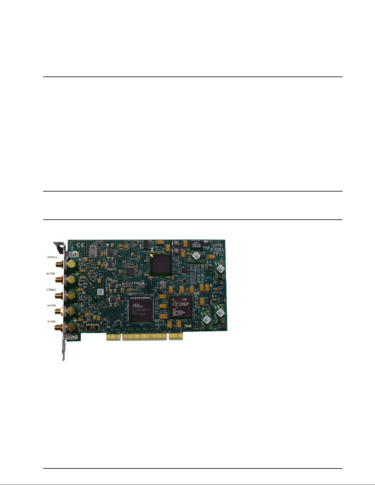
W-PCI/W-PCIe
The WAVECOM hardware decoder series W-PCI and W-PCIe have two physically independent 16-bit A/D
converters. Each card has five inputs in two groups: AFIF#1, IF70#1a and IF70#1b for the group#1 and
AFIF#2 and IF70#2 for the group#2. These two cards are suitable for protocols and systems which require two concurrent channels (e.g., the FAX/modem protocols, INMARSAT protocols etc.)
W-PCI/W-PCIe Hardware Installation
Before unpacking the W-PCI or W-PCIe card or installing it into your PC please make sure that you are attached to the electric ground to avoid damaging static sensitive components on the card or in the computer.
Power off your computer, unplug it from its power source and disconnect or turn off all peripherals. Carefully remove the cover of the computer and locate a free PCI or PCI express slot. Firmly insert the card into the slot. Close the computer cover and switch on the power.
WARNING: THE A/D CONVERTER ON THE W-PCI AND W-PCIe CARD MAY DEVELOPE ENOUGH
HEAT TO PRODUCE BURNS OR START A FIRE IF PLACED NEAR FLAMMABLE OBJECTS. WAVECOM
WILL NOT BE RESPONSIBLE FOR ANY DAMAGES RESULTING FROM NON-COMPLIANCE WITH
THIS WARNING.
W-PCI card.
WAVECOM Decoder W74PC, W-PCI/e, W-CODE, W-CLOUD Manual V9.1.0 Setup 11
Page 22
Specification
Card type
Half-size PCI card (W-PCI),
Half-size PCIe x1 card (W-PCI Express)
Inputs
AFIF#1 and AFIF#2
IF70#1a, IF70#1b and IF70#2
Frequency range
50 Hz – 25 MHz
52.5 MHz – 87.5 MHz (SAW filter)
Signal level
2 mVrms – 0.5 Vrms
20 mVrms – 2.5 Vrms
(with 20 dB attenuator)
20 mVrms – 2.5 Vrms
Input impedance
> 1 kOhm
50 Ohm
Bandwidth
5 kHz – 500 kHz
Frequency raster DDC
1.0 Hz
Input max sampling rate
92.16 MHz
Sampling rate jitter
1 ps
Connector
SMA female
Two simultaneously active inputs
AFIF#1 or IF70#1a or IF70#1b – with – AFIF#2 or IF70#2
Dimensions (LxWxH)
168x106x22 mm
Weight
150 g
Power requirement (typical values)
1.0 A @ +3.3 V, 0.4 A @ +12 V
Bus interface
32-bit PCI, 3.3 V, 132 MB/sec (W-PCI)
PCIe x 1, 250 MB/s (W-PCIe)
Operating temperature range
0 °C to 50 °C
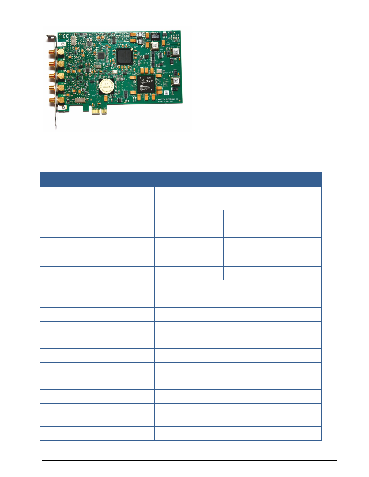
W-PCIe card.
Both W-PCI and W-PCIe cards have five SMA signal inputs. The following table is a technical hardware
specification.
12 Setup WAVECOM Decoder W74PC, W-PCI/e, W-CODE, W-CLOUD Manual V9.1.0
Page 23
Specification
Case temperature range
0 °C to 55 °C
Storage temperature range
0 °C to 70 °C
Relatively humidity (non-condensing)
10 to 90%
A/D converter
16-bit
Digital down converter (DDC)
FPGA
License key
In-card license, no external license key necessary
Conformity
W-PCI/W-PCIe Software Installation
(please refer to Software Installation W-CODE, W74PC, W-PCI and W-PCIe.)
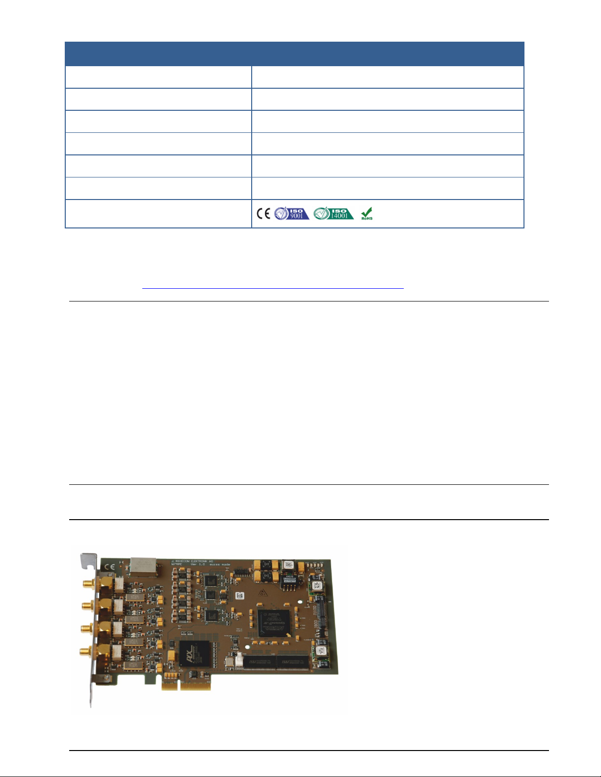
W74PC
The WAVECOM decoder hardware W74PC has four physically independent channels with two 16-bit A/D
converters. There are four SMA input connectors for input signal. Each SMA connector can be switched to
AFIF (50 Hz – 25 MHz) and IF70 (52.5 MHz – 87.5 MHz) by a signal relay. W74PC is suitable for decoding
signals and protocols which require multiple concurrent channels (e.g., the FAX/modem protocols, INMARSAT protocols etc.)
W74PC Hardware Installation
Before unpacking the W74PC card or installing it into your PC please make sure that you are attached to
the electric ground to avoid damaging static sensitive components on the card or in the computer.
Power off your computer, unplug it from its power source and disconnect or turn off all peripherals. Carefully remove the cover of the computer and locate a free PCI express x4 (or above) slot. Firmly insert the
card into the slot. Close the computer cover and switch on the power.
WARNING: THE A/D CONVERTER ON THE W74PC CARD MAY DEVELOPE ENOUGH HEAT TO PRODUCE BURNS OR START A FIRE IF PLACED NEAR FLAMMABLE OBJECTS. WAVECOM WILL NOT BE
RESPONSIBLE FOR ANY DAMAGES RESULTING FROM NON-COMPLIANCE WITH THIS WARNING.
W74PC card.
WAVECOM Decoder W74PC, W-PCI/e, W-CODE, W-CLOUD Manual V9.1.0 Setup 13
Page 24

Specification
Card type
Half-size PCIe x4 card
Inputs
AFIF#1 – AFIF#4
IF70#1 – IF70#4
Frequency range
50 Hz – 25 MHz
52.5 MHz – 87.5 MHz (SAW filter)
Signal level
2 mVrms – 0.5 Vrms
20 mVrms – 2.5 Vrms
Input impedance
> 1 kOhm
50 Ohm
Bandwidth
5 kHz – 500 kHz
Frequency raster DDC
< 1.0 Hz
Input max sampling rate
98.304 MHz
Sampling rate jitter
< 1 ps (RMS 12 kHz to 20 MHz)
Connector
SMA female
Number of concurrent, independent inputs
Four SMA connectors: AFIF/IF70#1 – AFIF/IF70#4, each switchable by a mini signal relay
Dimensions (LxWxH)
168x106x22 mm
Weight
150 g
Power requirement (typical values)
< 25W
Bus interface
PCIe x4 link, 2 Gbit/s
Operating temperature range
0 °C to 50 °C
Case temperature range
0 °C to 55 °C
Storage temperature range
0 °C to 70 °C
Relatively humidity (non-condensing)
10 to 90%
A/D converter
2 x AD9268 dual 16-bit ADC
Dynamic range
> 60 dB
Digital down converter (DDC)
FPGA Cyclone IV
Oscillator and clock
High stability temperatur compensated crystal oscillator. Low
phase noise clock distribution
Watchdog for on-board generated voltage
Yes
License key
In-card license, no external license key necessary
Conformity
W74PC has four SMA signal inputs. The following table is the technical hardware specification.
14 Setup WAVECOM Decoder W74PC, W-PCI/e, W-CODE, W-CLOUD Manual V9.1.0
Page 25
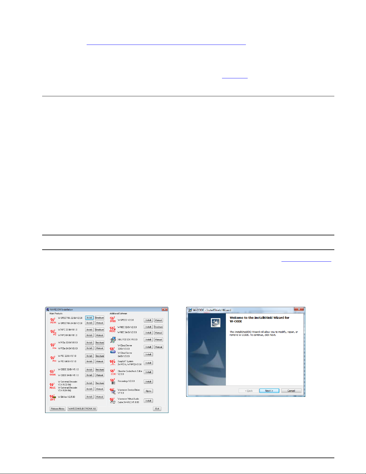
Click the “W-CODE” button to install the W-CODE
and W-CLOUD application.
First, you will see the welcome screen. Click
“Next” to continue the installation.
W74PC Software Installation
(please refer to Software Installation W-CODE, W74PC, W-PCI and W-PCIe.)
Wavecom Hardware Decoder License
Wavecom hardware decoders W-PCI, W-PCIe and W74PC use a 25-alphanumeric-digit key as license. The
license key is bound to the card serial no. Details please refer to “License...”.
W-CODE
The W-CODE application takes existing equipment of the customer, e.g., a soundcard or virtual soundcard
(VSC) as input device and works under a CmStick USB license key. This feature allows seamless integration with SDR (Software Defined Radio) receivers with IQ data, TCP/IP outputs or digital audio outputs via
virtual sound cards. Decoding from PC soundcards with sampling rates up to 192 kHz is also supported.
One client license is provided with each software package (multiple licenses on request). W-CODE provides all functions required to analyze, decode and process radio data communications over the entire frequency spectrum.
W-CODE Hardware Installation
Insert the USB licence key(s) in any USB socket.
Software Installation W-CODE, W74PC, W-PCI and W-PCIe
Insert the WAVECOM installation DVD in the drive. When requested, point the auto start wizard to the disc
drive and start installation.
Note: After installation, you can run the corresponding application W-CODE, W74PC, W-PCI and W-PCIe if
you are a member of the Administrators, Power Users or Users group.
Before the installation of a software update, the old version must be uninstalled (see “Software Uninstall”
on page 19). After uninstallation has completed, insert the WAVECOM installation disc in the drive; the installer will start automatically. Otherwise, it can be started with Windows Explorer by double-clicking
Installation.exe.
Without loosing generality we show the installation steps on the example W-CODE.
The selection dialogue of the installation program is displayed:
WAVECOM Decoder W74PC, W-PCI/e, W-CODE, W-CLOUD Manual V9.1.0 Setup 15
Page 26
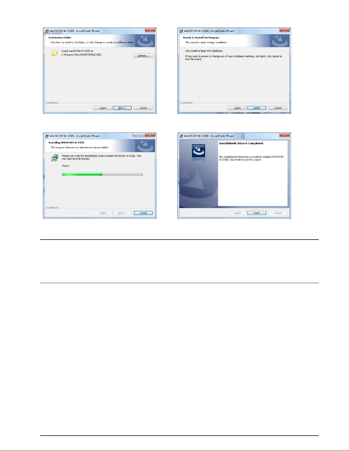
Change the destination folder and click “Next” to
continue the installation.
Click “Next” to continue the installation.
Wait until the installation is finished.
If the installation was successful, click Finish
to complete the process.
Note: If a firewall is enabled on your system, depending on its security level settings, various components
of W-CODE may ask to access the Internet or the trusted zone of the firewall. You will have to manually
grant access to these components.
Check for hidden windows if the installation process seems to “hang” (this can be done by pressing the
Alt+Tab keys). Sometimes windows in the background are waiting for a button to be pressed to allow the
installation to proceed.
W-CODE Server Control
The WAVECOM Server and the WAVECOM Server Control applications are used to setup and monitor the
connections between devices (clients) and the server, respectively. The server is responsible for managing
the devices (e.g., soundcards) in the computer as well as all the connections made to those devices. The
WAVECOM Server is started by the GUI for a local connection (GUI and devices on the same machine) or
by the Server Control for a remote connection. The WAVECOM Server is started as a Windows Service.
W-CODE Device Serial Number
The serial number of the audio device (soundcard or virtual audio cable VAC) is generated from part of the
active MAC address of the computer network interface and a counter.
W-CODE recognizes sound devices in the computer as its input devices. The serial number of a sound device comes from the built-in network card of the computer. The serial number is used as a reference for
custom inputs ans default settings. You will lose some settings if you switch to a different LAN adaptor,
e.g., switching from a LAN to a WLAN connection.
WAVECOM hardware W74PC, W-PCI and W-PCIe are detected by their corresponding application, they are
also listed in the Device dialog window with the device name and serial number. The serial number is
used as a reference for custom inputs and default settings. It is from the decoder hardware and will never
change.
16 Setup WAVECOM Decoder W74PC, W-PCI/e, W-CODE, W-CLOUD Manual V9.1.0
Page 27
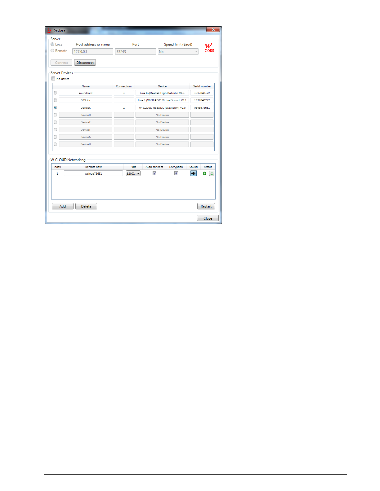
W-CODE Device dialog window.
W-CLOUD Networking
A W-CLOUD device is like a local W-CODE device, e.g., soundcard, W-PCI or W-PCIe cards. The only difference is a W-CLOUD device is physically at a remote site (over the internet) where the antenna and receiver are located. W-CLOUD device sends genuine and encrypted IQ signal to W-CODE for decoding.
In the W-CODE Device dialog window you can enter a W-CLOUD device by name (or IP address) and port
number. The connection can be made automatically upon restarting W-CODE (by pressing the “Restart”
button). The connection between W-CLOUD and W-CODE can be encrypted by checking the “Encryption”
box. Because the signal is received at a remote site, it is a big help to hear the signal at W-CODE site. This
is done by activate the “Sound” button. By pressing the “Check” button you may know the instantanuous
status of a W-CLOUD device.
A W-CLOUD device may have the following “Status”:
Available: W-CLOUD device is reachable, W-CODE can connect to it by restarting.
Offline: W-CLOUD device is unreachable.
Busy: W-CLOUD device is used by another W-CODE.
Connected: W-CLOUD device is connected by this W-CODE.
Denied: W-CLOUD device is reachable, but this W-CODE can not connect to it because this W-
CODE does not have the access right.
As W-CLOUD is a networking device, it should be accessable to different W-CODE decoder instances. Considering this W-CLOUD will terminate the connection to a W-CODE when W-CODE does not use this WCLOUD actively for ca. 7 minutes, i.e., no mode is running. After the 7 minutes time-out W-CLOUD device
is free for any new connection requests. The previous W-CODE can do decoding as usual by opening a
mode. The connection to the W-CLOUD device will be established automatically, if the W-CLOUD device is
not busy by another W-CODE instance. It may be that the re-established connection does not work
properly, the user just need to open a mode and change the device input to “wake-up” the connection.
WAVECOM Decoder W74PC, W-PCI/e, W-CODE, W-CLOUD Manual V9.1.0 Setup 17
Page 28
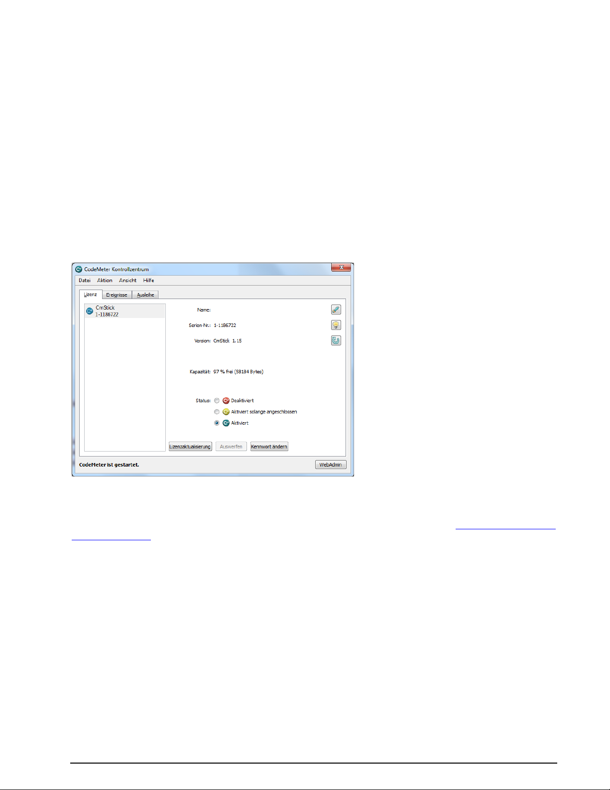
W-CODE Licensing
By default, W-CODE is licensed using a USB CmStick. An update option for a period of 12, 24, 36, 48, 60
months is available.
Optional additions to the basic W-CODE application are available from WAVECOM.
On request, different licensing models are available:
Single-user licenses
Network licenses with floating licenses (sharing of W-CODE and options between different comput-
ers)
Licenses for other WAVECOM software products and third party products may also be stored on
the CmStick
Software Updates
Software released during the update period can be installed at any time.
New licenses can be loaded to the CmStick without sending the key to WAVECOM. Just click License Up-
date on the CodeMeter Control Center and follow the information provided by the assistant.
How to update a license.
Software Options
Additional functions may be enabled and licensed to work with your decoder (see “License System, Soft-
ware and Options” on page 317).
Options are marked with (Option) in the manual.
Follow this procedure to order options:
The serial number of your CmStick must be provided and the desired options listed
WAVECOM will process your order and forward an invoice.
After the payment has been received, a new key or license file will be forwarded.
To process an order for options, the following information is required:
Complete address
Ordered items
Email or mail delivery
Serial number of CmStick
Remote context file of CmStick to be updated, if applicable
18 Setup WAVECOM Decoder W74PC, W-PCI/e, W-CODE, W-CLOUD Manual V9.1.0
Page 29

Press the “WebAdmin”.
Licenses available on the CmStick are listed in
this screen.
Item
Remarks
Product
Code
Displays the product code
Name
Displays the name of the product item, normally the name of the product
Feature
Map
Displays the feature map. WAVECOM uses the feature map to control the software update
period
Licenses
Displays the total number of network licenses
User Limit
Displays the number of licenses, which are currently used in the user limit mode
No User
Limit
Displays the number of licences that are currently used in the no user limit mode
Exclusive
Displays the number of licences that are currently used in the exclusive mode
Shared
Displays the number of licences that are currently used in the shared mode
Free
Displays the number of licences that are currently free
Details
Displays detailed information about the respective network licences in use
W-CODE License Checking
To check the license(s) on the CmStick follow these steps:
Open the CodeMeter WebAdmin interface from the CodeMeter tray icon.
Important: If you have multiple CmSticks plugged into computers to the same local network, refer to
“License System, Software and Options” on page 317.
Software Uninstall
In certain situations, e.g., when updating the application, it is necessary to uninstall the software. Use the
following commands:
WAVECOM Decoder W74PC, W-PCI/e, W-CODE, W-CLOUD Manual V9.1.0 Setup 19
Page 30

VISTA
XP
Windows 7
Click on Start, go to
the Computers menu
and click the Unin-
stall or change a
program button
Select WAVECOM W-
[XX] from the list
Click Uninstall
Click on Start, go to the
Settings menu and open
Control Panel
Select the Add/Remove
Programs icon
Select Install/Uninstall
Choose WAVECOM W-
[XX] from the list
Click Add/Remove
Click on Start and open the
Control Panel
Select the Programs icon
Select Programs and Fea-
tures
Choose WAVECOM W-[xx]
from the list
Click Uninstall in the menu
The application has now been removed from the PC - it is possible, however, that the shortcut icons may
have to be removed manually.
20 Setup WAVECOM Decoder W74PC, W-PCI/e, W-CODE, W-CLOUD Manual V9.1.0
Page 31

First start
W-CODE First Start
After the software and the CmStick have been successfully installed, the decoder program can be
started either from the Windows Start menu or by double-clicking the program icon on your desktop.
Proper operation of the decoder is indicated by the WAVECOM Server Control icon in the Windows
system tray. If the traffic light in the icon is green, then the server is operating normally. You may
also move the mouse over the icon and check that you get this status message: WAVECOM
Server – W-CODE (running).
The first time the software is used after the installation, you will have to set the decoder device
manually. From the menu bar, go to Configuration. A drop-down menu will appear. Click on the
W-CODE Device… menu item. A setup window appears.
WAVECOM Decoder W74PC, W-PCI/e, W-CODE, W-CLOUD Manual V9.1.0 First start 21
Page 32
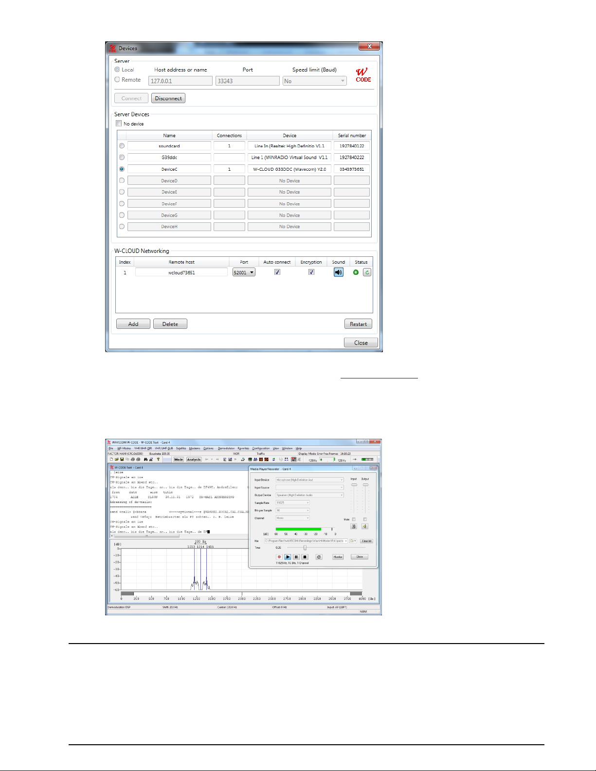
Select a device number and click Close to save the entry. If you require more details regarding
remote connections and connection parameters see “W-CODE Device…” on page 52.
The decoder is now ready for use. Apply a signal to the selected input or use the Media Player
Recorder to play back a WAV file.
From the HF-Modes, VHF/UHF-Modes or Satellite menus a mode may be selected, e.g.,
PACTOR-II if a PACTOR-II signal is played back.
Tune the demodulator to the correct center frequency and set the correct input level.
GUI
The user interface of the application conforms to standard WINDOWS interface guidelines. The main program window is shown in this section. This is the window you will see after setup has been completed as
described in the preceding paragraphs.
22 First start WAVECOM Decoder W74PC, W-PCI/e, W-CODE, W-CLOUD Manual V9.1.0
Page 33

The WINDOWS elements TOOLBAR, WAVECOM TOOLBAR, LEVEL INDICATOR and SPECTRUM INDICATOR may be moved anywhere in the screen as required. In the View menu the user may show or hide
all window elements. By default, all elements are visible.
Please be aware that the appearance of the GUI will vary depending on the product, software version and
operating system.
Command Line Parameters
You can pass information to the application by adding command line parameters.
The following commands are valid:
/i <ini file name>
The name of the INI file that is located in the same directory as the decoder application. Alternatively a
path may be entered.
/n <card number>
The number of the card to be connected (a value between 1 and 8).
/c <computer>
The name of the computer to be used for the connection
localhost (not case sensitive) or 127.0.0.1 means that you work with cards on the local comput-
er.
Computer name or the IP address plus the port number to connect to another computer. The port
number must be entered on the WAVECOM Server Control screen. If a port number is not provided, then default port 33233 is used.
/l <speedlimit>
Speed limit of the connection to the server. This attribute is a choice of “9600”, “14400”, “19200”,
“56k”, “64k”, “128k”, “512k”, “1M”, “2M”, “5M”or “10M”. If no /l option is used, the speed is un-
limited.
Examples (for W-CODE):
WCODE.EXE /i config1.ini
WCODE.EXE /i "\configuration\setupAB.ini"
WCODE.EXE /n 2 /c WCODEServer:5800
WCODE.EXE /n 1 /c 192.168.1.12:8080
WCODE.EXE /n 3 /c 192.168.2.5
WCODE.EXE /n 3 /c 192.168.2.5 /l 56k
Default Data and Program Folders (Paths)
To see all folders, select Folder Options in the Control Panel
Enable Show all folders.
Enable Show hidden files, folders and drives
WAVECOM Decoder W74PC, W-PCI/e, W-CODE, W-CLOUD Manual V9.1.0 First start 23
Page 34
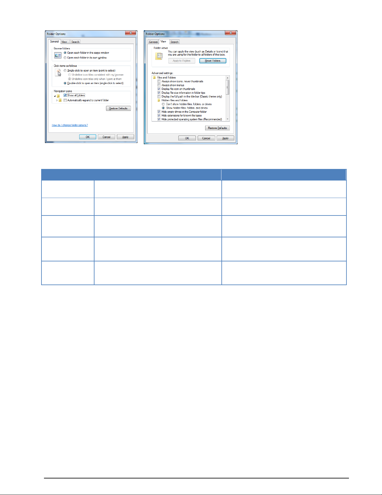
Folder
XP
Vista
Program Folder (RO)
C:\Program Files\WAVECOM\<Product>\
C:\Program Files\WAVECOM\<Product>\
Global Data
(RO)
C:\Documents and Settings\All Users\Application Data\WAVECOM\<Product>\
C:\ProgramData\WAVECOM\<Product>\
Global Data
(RW)
C:\Documents and Settings\All Users\Documents\WAVECOM\<Product>\
C:\Users\Public\Public Documents\
WAVECOM\<Product>\
User Specific
Roaming Data
C:\Documents and Settings\\<Username>\\Application Data\
WAVECOM\<Product>\
C:\Users\<Username>\AppData\Roaming\
WAVECOM\<Product>\
User Specific
Non-Roaming
Data
C:\Documents and Settings\<Username>\Local Settings\Application
Data\WAVECOM\<Product>\
C:\Users\<Username>\AppData\Local\
WAVECOM\<Product>\
Path names can vary if you use a non- English language operating system or if you are not using the Microsoft “Windows Explorer”.
24 First start WAVECOM Decoder W74PC, W-PCI/e, W-CODE, W-CLOUD Manual V9.1.0
Page 35
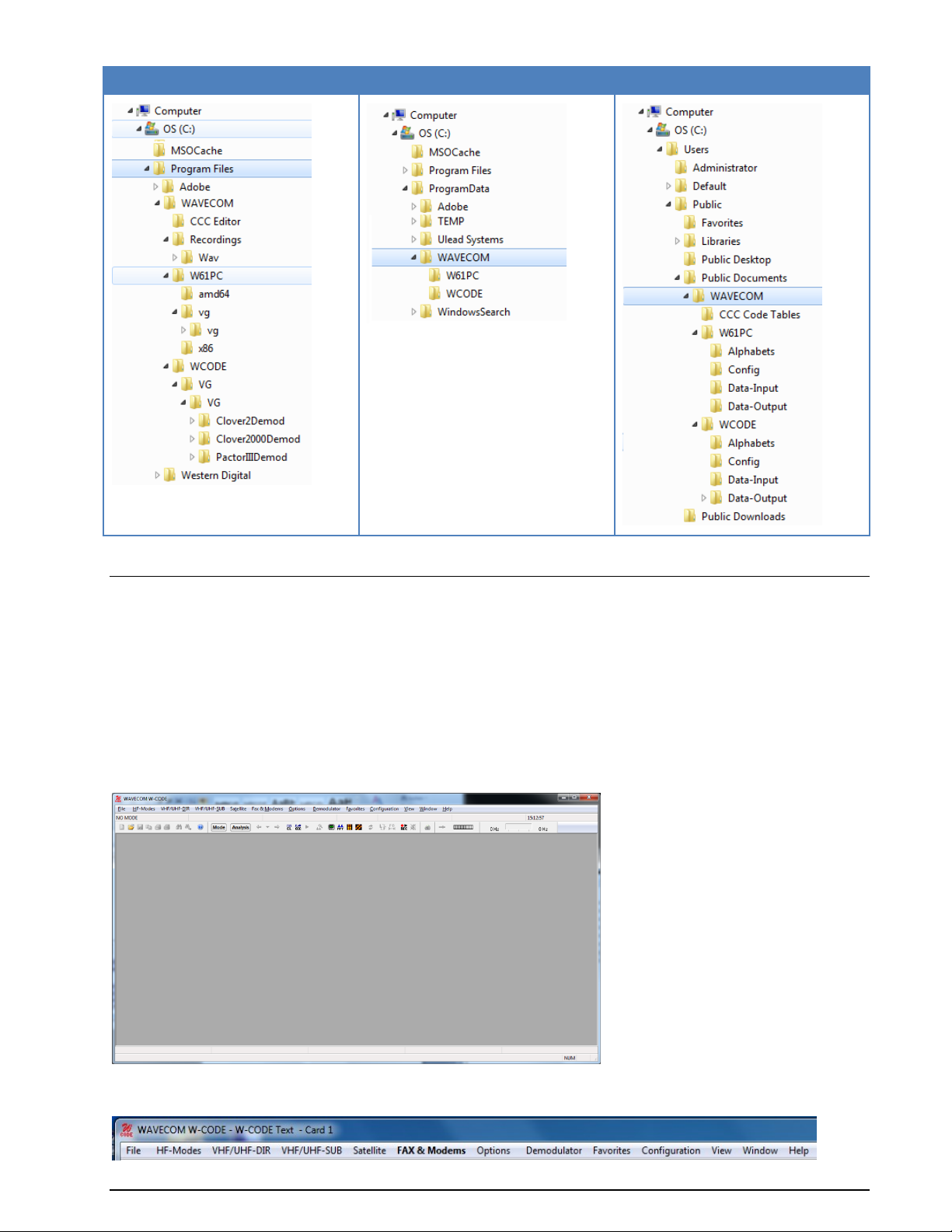
Program Folder
Global Data (RO)
Global Data (RW)
Graphical User Interface (GUI)
Main Menu
The main menu includes all submenus relating to operating modes, as well as analysis and setup functions.
The WINDOWS operating system is based on a multitasking kernel and can handle several tasks simultaneously, and therefore interaction with the menu system will not interrupt the execution of an active function. This allows, for example, the shift and center frequency to be set in the Demodulator submenu
without disrupting the currently active operating mode.
Main Menu Screen Display
This window is displayed without any mode started.
As a standard WINDOWS procedure a left-click on a menu item will display the corresponding drop-down
menu.
WAVECOM Decoder W74PC, W-PCI/e, W-CODE, W-CLOUD Manual V9.1.0 First start 25
Page 36
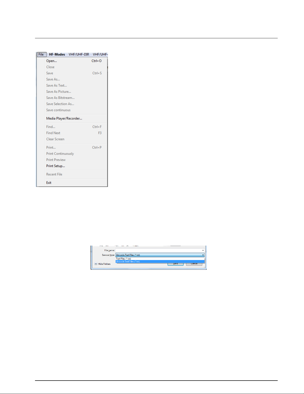
Open…
Open previously saved files
Save
Save received text to an already open text file. If no file is open “Save As...” will be started
to ask for a valid path and file name
Save As…
You can specify a path and file name and save the received text to this file
Save As Text...
Save received text as an ASCI or Unicode file
Save As Bitstream...
Save a bit stream e.g., from an auto-correlation session as a text file of ASCII 0’s and 1’s
Save As Picture…
Save the main window as a JPEG, a BMP or a PNG file
Save Selection as...
Select a block of text and save it to a text file
Save Continuously
Save continuously all output to a file
Media Player/Recorder
Record and play back WAV files
Find
Search for every occurrence of a specific word or phrase in the received text
Find Next
Find the next occurrence of a specific word or phrase in the received text
Clear Screen
Prompts the user to clear the screen
Print
Send the received text to a printer
Print Continuously
Send continuously all output to a printer
The functions of the File, View and Window menus are general system functions in accordance with the
WINDOWS standard.
File Menu
Using the File menu, files may be saved and opened. Other functions such as the Media Player/Recorder,
find, printing, print preview and printer setup are also available.
26 First start WAVECOM Decoder W74PC, W-PCI/e, W-CODE, W-CLOUD Manual V9.1.0
Page 37
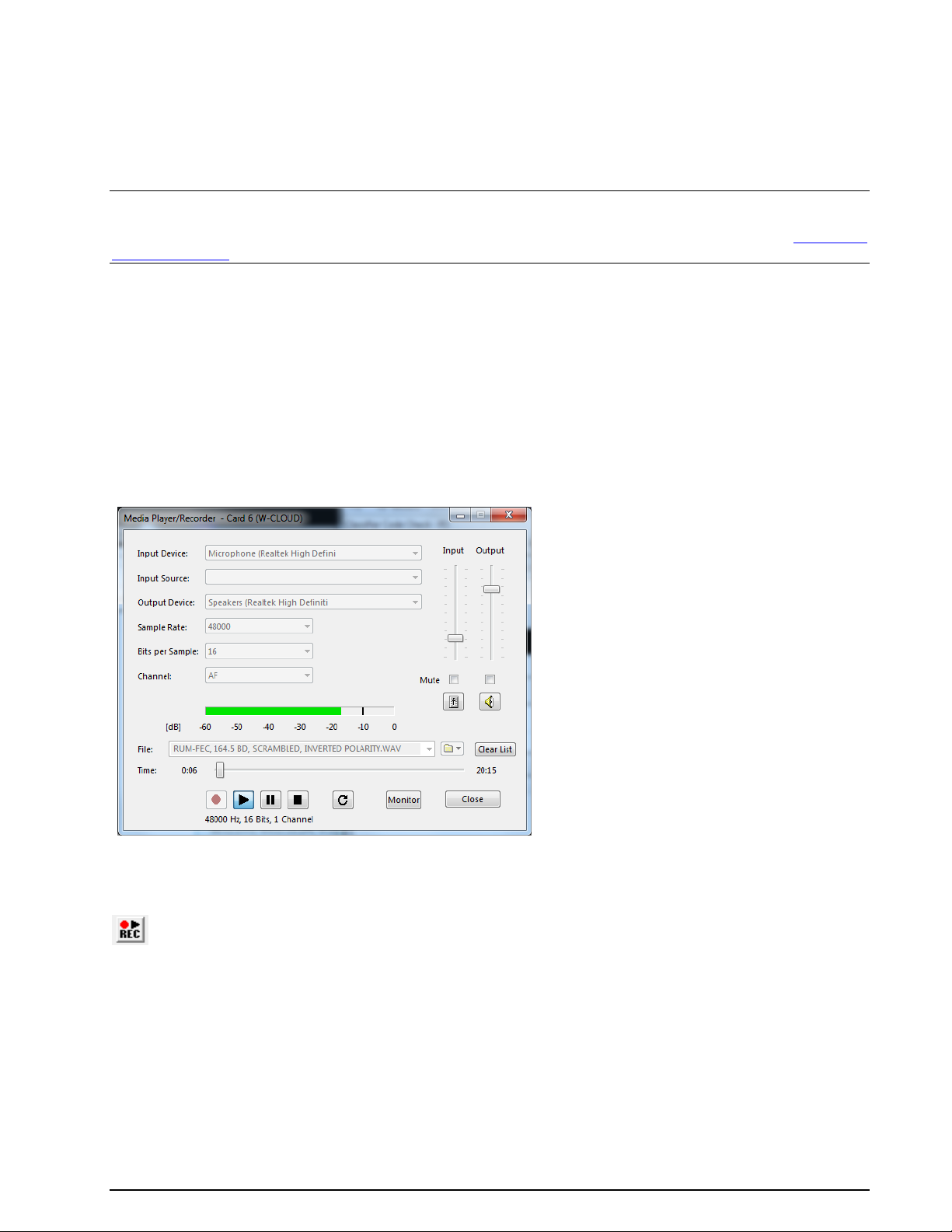
Print Preview
Preview the output before sending it to the printer
Print Setup…
Open the printer setup dialog
Recent File
Displays a list of recently opened files
The Media Player/Recorder dialog can be closed and reopened at any time. Any playback or recording operation that is in progress when the dialog is closed will continue uninterrupted in the background.
Note: Files that are saved with Save and Save as... are stored in the WAVECOM *.WDA format. This
format is used to save decoded text together with time stamps in a text file. The import of old *.W40
(W40PC), *.W41 (W41PC) and *.W51 (W51PC) files is also supported. For more details see “WAVECOM
Data File Format” on page 333.
Media Player/Recorder
The Media Player/Recorder enables the user to record and save audio signals as WAV files for later playback to the W-CODE decoder.
Audio signals are recorded directly from the local sound card and saved as WAV files on the host computer. The input can be a physical device (a soundcard) or a virtual device (a virtual audio cable VAC). During
playback, the audio signal is sent directly to the W-CODE decoder in digital format without any further
processing or conversion - the sound card is completely bypassed. To enable the user to monitor the signal, the signal is also routed to the local host sound card output.
The Media Player/Recorder is controlled from the Media Player/Recorder dialog:
The Media Player/Recorder dialog can be opened from either the File->Media Player/Recorder…
menu, or from a toolbar button:
WAVECOM Decoder W74PC, W-PCI/e, W-CODE, W-CLOUD Manual V9.1.0 First start 27
Page 38
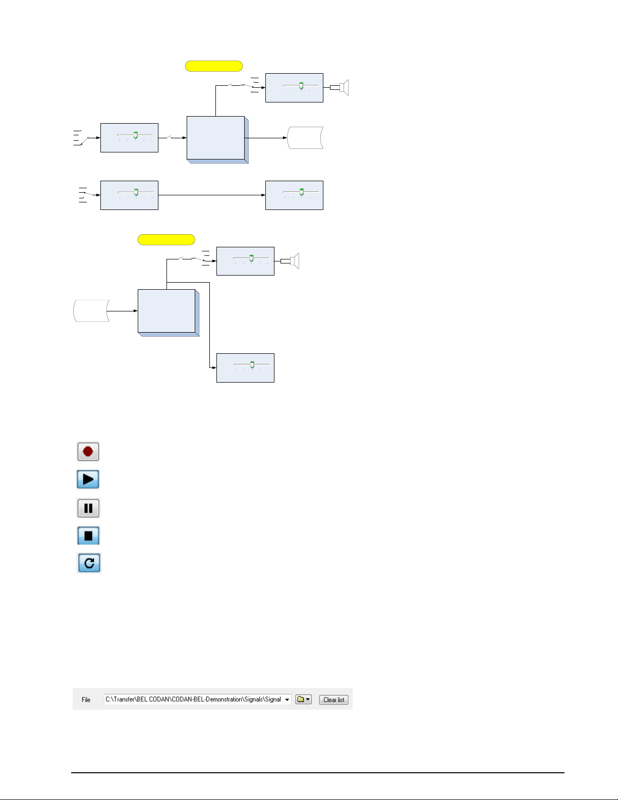
Record
Play
Pause
Stop
Loop
Windows Audio System
WAVECOM Media Player/
Recorder
W-CODE
Disk
File Recording
Input Device
Mute
Output Device
Output
Mute
Windows Audio System
Input
Recording
Input Device
Windows Audio System
Input
Decoder Gain
Playback
Windows Audio System
WAVECOM Media Player/
Recorder
Disk
Recorded Files
Mute
Output Device
Output
W-CODE
Decoder Gain
Signal Routing: Media Player Recording
Signal Routing: Media Player Playback
Main Control Buttons
The Media Player/Recorder is controlled primarily using the main control buttons:
Press the Record button to start recording and the Stop button to stop recording. Press the Play button
to start playback and the Stop button to stop playback. Playback and recording can be paused and resumed at any time by pressing the Pause button. When the Loop button is toggled on, playback will automatically restart from the beginning when the end of the file is reached. If the Loop button is not
pressed, playback will stop at the end of the recording.
WAV File
Before starting a playback or recording operation, the user must specify the WAV file to read from or write
to in the Media Player/Recorder dialog:
The name of the file can either be specified by typing the full file path into the text box, or by pressing the
folder button to browse for the required file. A list of the 10 most recently used files is also available by
pressing the down arrow on the right of the text box.
28 First start WAVECOM Decoder W74PC, W-PCI/e, W-CODE, W-CLOUD Manual V9.1.0
Page 39
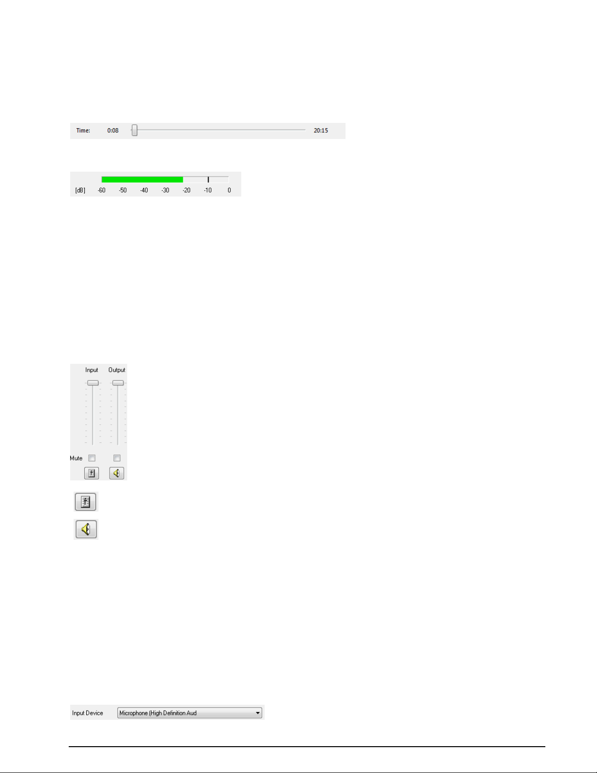
To open the recording mixer press the 'Recording Level' button
To open the playback mixer press the 'Playback Level' button
Clear List clears the list of previously used files.
Time Display
During the recording process, the current length of the recording (in minutes and seconds) is displayed at
the left side and the total time of the recording (in minutes and seconds) is displayed at the right side.
During playback, the current position is shown in the time display along with a slider that shows the relative position in the file:
The user can fast-forward or rewind by dragging the slider with the mouse.
Level Indicator
A level indicator is provided to monitor the sound level. While playing a WAV file, the level indicator shows
the level of the file being played. At all other times (during recording or while stopped), the level indicator
shows the level of the sound present on the selected host sound card input.
For stereo audio, the level indicator displays two bars, one for each of the left and right channels. For
mono audio, a single bar is displayed.
The average signal power and peak signal power is calculated every 50ms. The average signal power is
displayed as a green bar in the level indicator, while the peak level is displayed as a black line. Both of
these power levels are expressed in dB, with reference to 0dB Full Scale. When adjusting the sound level
for recording it is important to ensure that the peak signal power (the black line) is as high as possible,
yet never touches the 0 dB mark. Failure to keep the peak signal power below the 0dB mark will result in
a clipped or distorted recording.
Mixer Control
Access to the Windows Mixer is provided directly from the Media Player/Recorder:
The functionality provided by the Windows Mixer depends on the host sound card and the version of the
operating system installed. For more information, see the documentation provided by your host sound
card manufacturer.
Quick access to the most commonly used functionality in the Windows Mixer is provided via a gain slider
and mute button. These controls are linked directly to their counterparts in the Windows Mixer. Adjusting
one will also adjust the other. On Windows XP, the output slider and mute button will control the “Wave”
mixer control. On Windows Vista and later, it controls the “Volume” for the W-CODE application.
Recording Controls
Most sound cards are equipped with more than one input source, e.g., Line-In 1, Line-In 2, S/PDIF-In, etc.
Additionally, some computers are fitted with more than one sound card. Before a recording can be made,
the user needs to choose the sound card device and sound card input that will be used for the recording.
To select the sound card use the Input Device control:
WAVECOM Decoder W74PC, W-PCI/e, W-CODE, W-CLOUD Manual V9.1.0 First start 29
Page 40
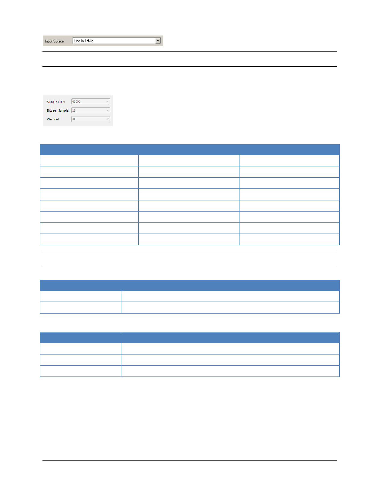
Sample Rate
Signal Bandwidth
Remarks
8 kHz
4 kHz
11.025 kHz
5.5 kHz
16 kHz
8 kHz
22.05 kHz
11 kHz
44.1 kHz
22 kHz
48 kHz
24 kHz
Recommended
96 kHz
48 kHz
192 kHz
96 kHz
Bits per Sample
Dynamic Range
8 bits
48 dB
16 bits
96 dB
Channels
Recording Source
AF Left
Records left channel only
AF Right
Records right channel only
IQ (Left & Right)
Records both channels
To select the source use the Input Source control:
Note: On Windows Vista and later, all input sources from all sound cards are listed under the 'Input Device' control, and the 'Input Source' control is not available.
Various combinations of sampling rate and bits per sample can be chosen when recording WAV files, and
the output file can be either mono or stereo. To set the WAV file recording format use the following controls:
Sample Rate needs to be set to twice the required signal bandwidth. The following sample rates are supported:
Note: Not all sound cards will support all of these sample rates. For further details see the documentation
provided by your host sound card manufacturer.
Bits per Sample can be set to either 8 bits or 16 bits depending on the required dynamic range:
Audio can be recorded in stereo or mono. When recording in mono, either the left or right channel can be
recorded. The Channel control provides the following options:
On sound cards that are not capable of stereo sound, only one option (namely 'AF') is available.
30 First start WAVECOM Decoder W74PC, W-PCI/e, W-CODE, W-CLOUD Manual V9.1.0
Page 41
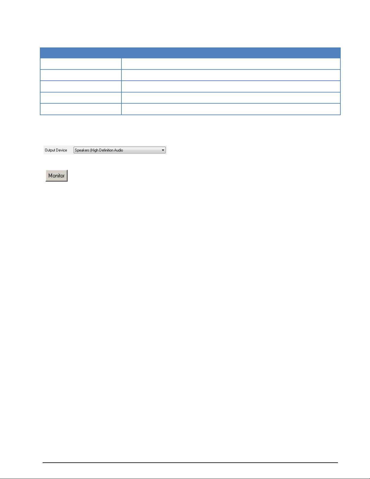
Format
Max recording length
8kHz, 8-bit, AF
149 hours, 7 min
8kHz, 16-bit, AF
74 hours, 33 min
48kHz, 16-bit, AF
12 hours, 25 min
48kHz, 16-bit, IQ
6 hours, 12 min
192kHz, 16-bit, IQ
1 hour, 33 min
The monitor function allows the user to listen to the audio signal connected to the sound card input.
Press the Monitor button toggle this function on and off.
The WAV file format supports files up to a maximum size of 4 GB. The maximum length of recording that
can be made depends on the sample rate, number of channels and bits per sample. The table below lists
the maximum recording lengths for a few common formats:
Playback Controls
Sound playback can be routed to the output of any installed sound card. To select the sound card that will
be used for playback, use the Output Device control:
Monitor Function
The monitor function works by playing back the recorded signal in real time. A circular buffer is used resulting in a small delay between the input and output signal.
A problem may occur when monitoring an input from one sound card to an output on another sound card,
where the sampling clocks used for the input and output will not be synchronized. On some sound cards
different clocks are used for input and output, resulting in the same problem. In these cases the monitor
function may produce sound with occasional skips and interruptions - this is normal, and will not affect the
integrity of recorded sound.
Some sound cards have an input labelled something like “What You Hear” or “Wave Out” allowing the recording of sound produced by other applications on the computer. When these inputs are selected, the
monitor function should not be used as it will create a feedback loop.
Record a Signal from Wavecom Hardware Devices
Media Player/Recorder can also be used to record a signal on a Wavecom hardware device, including WCLOUD. This is done via Wavecom Virtual Audio Cable (W-VAC). User can select W-VAC as the “Input De-
vice”, the signal on a Wavecom hardware device is redirected to the W-VAC and thus can be recorded by
pressing the “Record” button. The signal format is IQ in general; for audio signal one channel (Left or
Right) is just of zero value.
WAVECOM Decoder W74PC, W-PCI/e, W-CODE, W-CLOUD Manual V9.1.0 First start 31
Page 42

HF-Modes Menu
The various HF protocols are displayed in the HF-Modes menus and are divided into different groups. To
select the modes of a group, left-click or let the mouse rest briefly on the group item to be selected. Now,
the modes of the group are displayed in a separate menu. Start decoding the desired mode by another
left-click.
It may be difficult to guess or remember to which group a particular mode belongs. To facilitate an overview, a full-screen menu may be opened by clicking the menu item Mode Selector. To start a mode, click
on the appropriate menu field. Leaving the full-screen menu will not terminate an active mode.
The various analysis tools available are displayed in the Analysis menus.
Descriptions of the operating modes in a separate section of this manual are arranged in alphabetical order.
The Mode Selector is available from the HF-Modes menu and from the WAVECOM Toolbar.
32 First start WAVECOM Decoder W74PC, W-PCI/e, W-CODE, W-CLOUD Manual V9.1.0
Page 43

HF-Modes | Analysis
HF-Modes | FSK
HF-Modes | MFSK
HF-Modes | PSK & OFDM
HF-Modes are organized as follows:
WAVECOM Decoder W74PC, W-PCI/e, W-CODE, W-CLOUD Manual V9.1.0 First start 33
Page 44

HF-Modes | MIL-STANAG & HF-ACARS
HF-Modes | Graphic Modes and CW
HF-Modes | Mode Selector...
See “Mode Selector” on page 73.
VHF/UHF-DIR | Analysis
VHF/UHF-DIR | Modes
VHF/UHF-DIR | Mode Selector...
See “Mode Selector” on page 73.
VHF/UHF-DIR Menu
DIRECT modes can only be demodulated at the intermediate frequency level IF (analogue or IQ). The
various VHF/UHF-DIR protocols are displayed in the VHF/UHF-DIR menu. To start decoding of the desired mode, click on it.
The various analysis tools are displayed in the Analysis menus.
The descriptions of the operating modes in a separate section of this manual are arranged in alphabetical
order.
The Mode Selector is available from the VHF/UHF-DIR menu and from the WAVECOM Toolbar.
34 First start WAVECOM Decoder W74PC, W-PCI/e, W-CODE, W-CLOUD Manual V9.1.0
Page 45

VHF/UHF-SUB | Analysis
VHF/UHF-SUB | Modes
VHF/UHF-SUB | Selcal Analog
VHF/UHF-SUB | Mode Selector...
See “Mode Selector” on page 73.
VHF/UHF-SUB Menu
INDIRECT modes require additional AM or FM demodulation in the receiver. If the signal is demodulated
from an IF-IQ signal (offset frequency <> 0), then a standard AM or FM software demodulator is automatically added to the signal processing path.
The various VHF/UHF-SUB protocols are displayed in the VHF/UHF-SUB menu. To start decoding of the
desired mode, click on it.
The various analysis tools are displayed in the Analysis menus.
The descriptions of the operating modes in a separate section of this manual are arranged in alphabetical
order.
The Mode Selector is available from the VHF/UHF-DIR menu and from the WAVECOM Toolbar.
WAVECOM Decoder W74PC, W-PCI/e, W-CODE, W-CLOUD Manual V9.1.0 First start 35
Page 46

Satellite | Analysis
Satellite | Modes
Satellite | INMARSAT-AERO
Satellite | INMARSAT-B
Satellite Menu
The various satellite protocols are displayed in the Satellite menu. To start decoding of the desired mode,
click on it or to select the modes of a group, left-click or let the mouse rest briefly on the group item to be
selected. Now, the modes of the group are displayed in a separate menu. Start decoding the desired mode
by another left-click.
The various analysis tools are displayed in the Analysis menus.
The descriptions of the operating modes in a separate section of this manual are arranged in alphabetical
order.
The Mode Selector is available from the Satellite menu and from the WAVECOM Toolbar.
36 First start WAVECOM Decoder W74PC, W-PCI/e, W-CODE, W-CLOUD Manual V9.1.0
Page 47

Satellite | INMARSAT-C
Satellite | INMARSAT-mM
Satellite | INMARSAT-M
Satellite | Mode Selector...
See “Mode Selector” on page 73.
FAX & Modems Menu
The various modem protocols are displayed in the FAX & Modems menu. To start decoding of the desired
mode, click on it or to select the modes of a group, left-click or let the mouse rest briefly on the group
item to be selected. Now, the modes of the group are displayed in a separate menu. Start decoding the
desired mode by another left-click.
The various analysis tools are displayed in the Analysis menus.
The descriptions of the operating modes in a separate section of this manual are arranged in alphabetical
order.
The Mode Selector is available from the FAX & Modems menu and from the WAVECOM Toolbar.
WAVECOM Decoder W74PC, W-PCI/e, W-CODE, W-CLOUD Manual V9.1.0 First start 37
Page 48
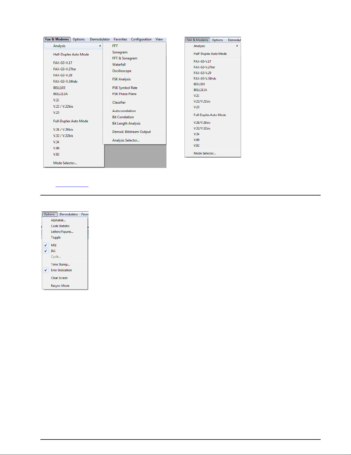
FAX & Modems | Analysis
FAX & Modems | Modes
Fax & Modems | Mode Selector...
See “Mode Selector” on page 73.
Options Menu
In the Options menu all supported functions for a particular mode or functionality are collected - the
menu is adapted to each individual mode. The Options menu will therefore appear with different contents
depending on the mode or functionality selected.
Alphabet...
The Alphabet menu has options for transparent and normal output. The normal output includes fonts for
e.g., Latin, Greek, Cyrillic, Hebrew, Arabic alphabets.
The ASCII character sets for output in German, Bulgarian, US, Swedish, Danish-Norwegian, Chinese
or other alphabets may also be selected.
Skyper, an alphabet which is used in POCSAG mode in Germany, is also available.
The transparent alphabet includes output of non-printable characters of a data transmission, e.g., ITA-2
control characters like Letter Shift and Figure Shift, or undefined upper case characters. In normal alphabets these characters are not output.
Auto Decrypt
Decryption can be switched on/off with Options | Auto Decrypt. If enabled, the key is displayed in the
status bar.
38 First start WAVECOM Decoder W74PC, W-PCI/e, W-CODE, W-CLOUD Manual V9.1.0
Page 49
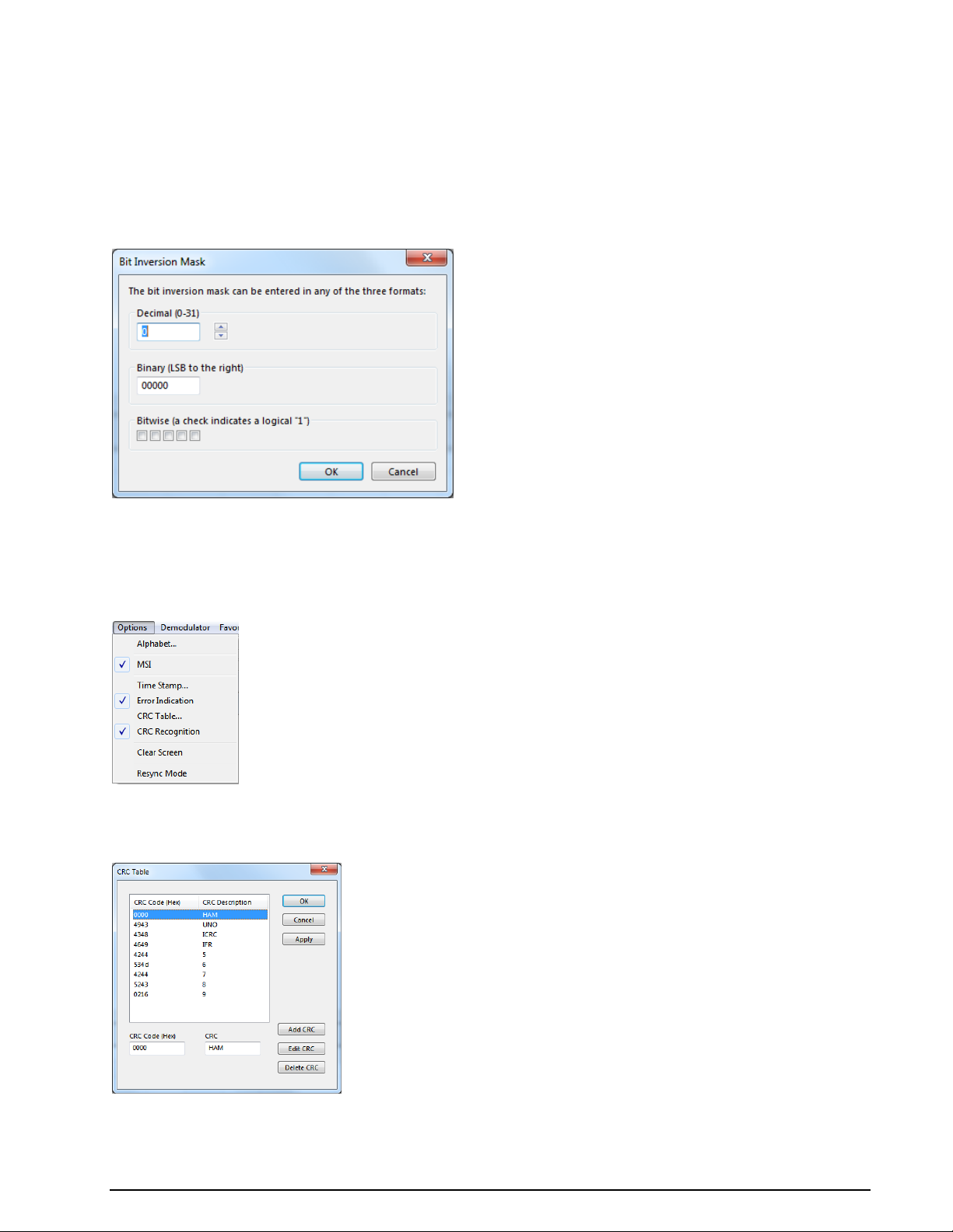
Bit Inversion Mask
One or several data bits may be inverted by using the Bit Inversion Mask item in the Options menu.
The Bit Inversion Mask can be entered in three different ways:
In the top input box a decimal number between 0 and 31 may be entered
In the center input box the same number may be entered in binary format with the least signifi-
cant bit to the right
In the bottom check boxes a logical "1" is entered with the mouse by clicking in the check box
Bit Inversion is only implemented for ITA-2 (Baudot) based bit streams.
CRC Recognition
An automatic detection of the CRC can be switched on/off with Options | CRC Recognition. The detected CRC is displayed in the decoder status bar.
CRC Table
Using Option | CRC Table a certain CRC mask can be defined.
A table of CRC's is stored in \Config\CRCTable.xml.
WAVECOM Decoder W74PC, W-PCI/e, W-CODE, W-CLOUD Manual V9.1.0 First start 39
Page 50
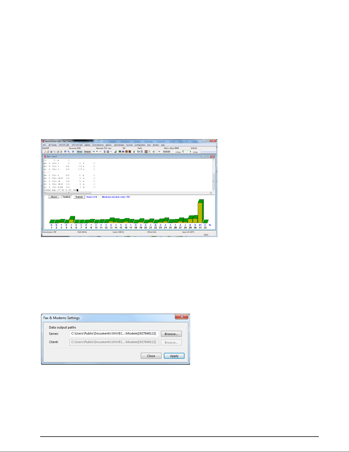
Clear Screen
This function will clear the screen contents. All data will be lost.
Code Statistics
For five bit alphabets a code statistics window can be shown below the text window. In the Options menu
chose Code Statistics to switch the statistic window on or off.
The bottom row shows the decimal value of the characters. The row above displays the number of characters as a percentage.
The statistics are displayed as a 3D bar graph, with the height of the bars proportional to the number of
instances of a given character.
Click on the Reset button to reset all counters to zero.
Press the Enabled button to toggle sampling of the received characters for the statistics on and off.
Using the Statistics button the data can be showed ordered by quantity.
Cycle...
In some modes, the character repetition cycle may be manually selected.
Error Indication
If Error Indication is switched on, then characters containing errors are marked in red color. If possible,
the error correction will correct the erroneous data.
FAX & Modems Settings
For the FAX & Modems modes, additional parameters regarding the output location can be set in the Options | FAX & Modem Settings dialog box.
These settings are:
Server: The path to the specific output directory has to be specified
Client: The path to the specific output directory has to be specified. This option is only enabled in
remote mode
40 First start WAVECOM Decoder W74PC, W-PCI/e, W-CODE, W-CLOUD Manual V9.1.0
Page 51

Frame Format…
IAS
IAS is the abbreviation for ISO-ASYNCHRONOUS and SYNCHRONOUS modes. Iso-asynchronous modes
have start and stop elements like Baudot, but the code words have an integer number of elements. The
IAS function is used for the extremely accurate baud rate estimation of a synchronous or isoasynchronous bit stream.
The automatic phase correction for the ideal bit center sampling (bit synchronism) is completely independent of the IAS function and is always active. The extremely accurate baud rate determination uses
the number of necessary phase correction steps for the baud rate determination.
In modes working with an interrupted data stream such as PACKET-300, it may be advantageous to be
able to switch off the baud rate correction to prevent drifting of the pre-selected baud rate. When the IAS
function is disabled, any pre-selected variable baud rate will be treated in the same way as a fixed baud
rate.
In most of the VHF/UHF modes the IAS is permanently disabled. This is due to the lack of phase coherence between successive data blocks. An exact measurement of the phase shift is not possible for an extended period of time.
In the event of adverse HF reception conditions (fading), enabling IAS may offer substantial advantages.
The software will decrease the size of the phase correction steps in accordance with the verified, reduced
phase errors, and thus prevent bit glitches and the resulting loss of synchronism. It is therefore recommended to enable IAS as a default.
Tick the IAS menu item to enable IAS.
Letters/Figures...
This option is only available for ITA-2 based modes.
The Letters/Figures dialog box contains the options Normal, Letters Only, Figures Only and Unshift
on Space (UOS). Letters and Figures designates the ITA-2 lower (letters) and upper (figures) cases.
For reception under normal conditions the selection of one case or the other is controlled by the reception
of the shift characters.
Special alphabets, e.g., Chinese, comprise only letters so forcing a shift into lower case mode may be an
advantage (Letters Only). Selecting this function may also be advantageous when searching for a bit inversion pattern, as the pattern may be more easily recognized.
In weather code transmissions five figure groups are used - in this case one may force a shift into upper
case (Figures Only).
The Unshift on Space (UOS) function forces a shift into lower case after a space character has been received. In this manner the readability of the transmission may be enhanced under poor conditions (weak
signals or interference).
Compared to the Letters Only mode, UOS has the advantage that single, upper case characters like periods/full-stops and commas are correctly printed. The drawback is that the software will incorrectly shift to
lower case when receiving figure groups separated by space characters.
Message Type...
These are mode specific parameters.
WAVECOM Decoder W74PC, W-PCI/e, W-CODE, W-CLOUD Manual V9.1.0 First start 41
Page 52
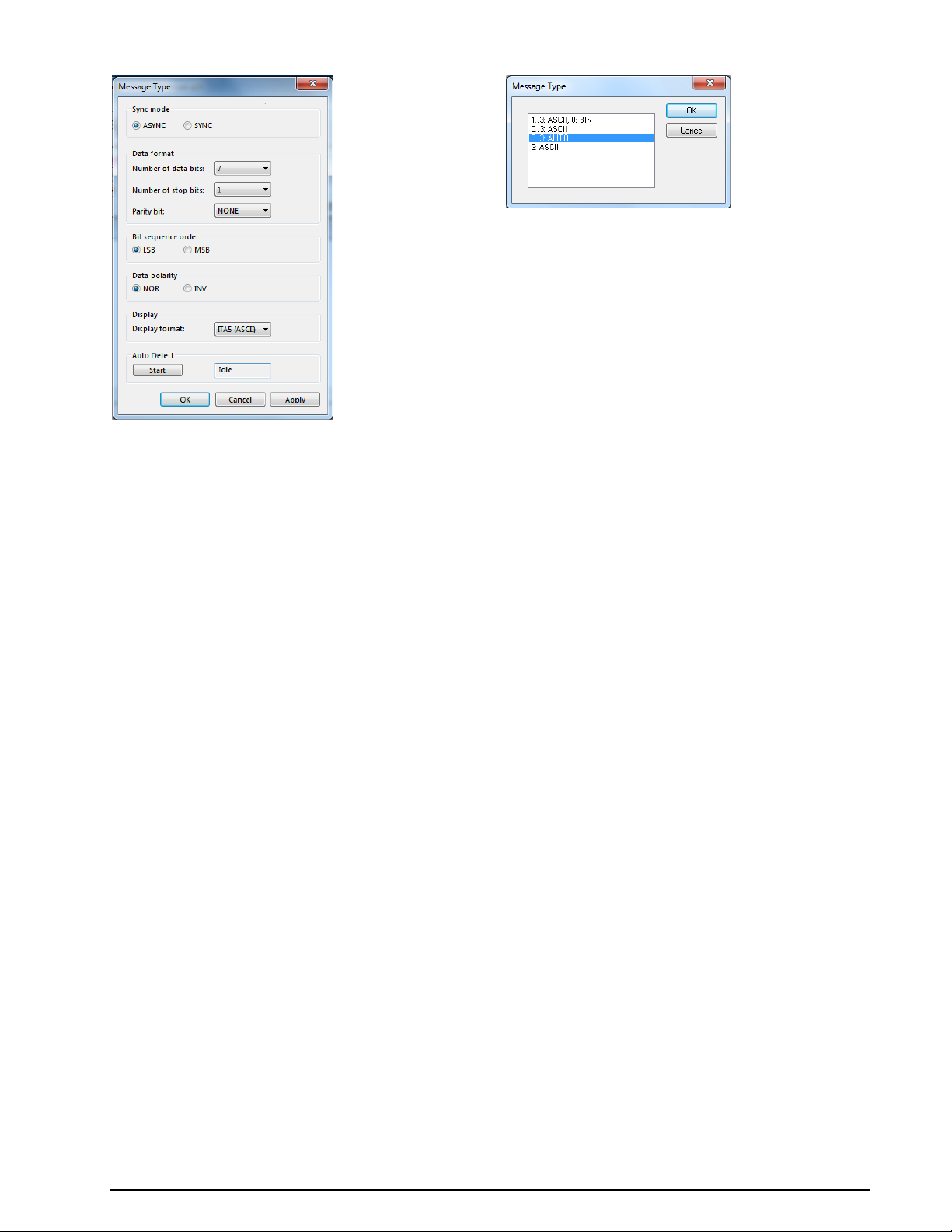
Message Type is used to apply terminal specific settings like:
SYNC/ASYNC
Number of databits
Parity bits
- NONE
- EVEN
- ODD
- MARK
- SPACE
Number of stop bits
Bit Sequence order
- MSB
- LSB
Display format
- ITA5 (ASCII)
- ITA2
- HEX
- BINARY
- S5066: The STANAG5066 parser can be used with the NATO and MIL-STD modems (like
STANAG4285, STANAG4539, MIL-STD-110…)
- Display format
If you press the Activate Button, the software tries to evaluate the following parameters:
- SYNC/ASYNC
- Number of databits
- Parity bits
- Number of stop bits
- Display format
42 First start WAVECOM Decoder W74PC, W-PCI/e, W-CODE, W-CLOUD Manual V9.1.0
Page 53
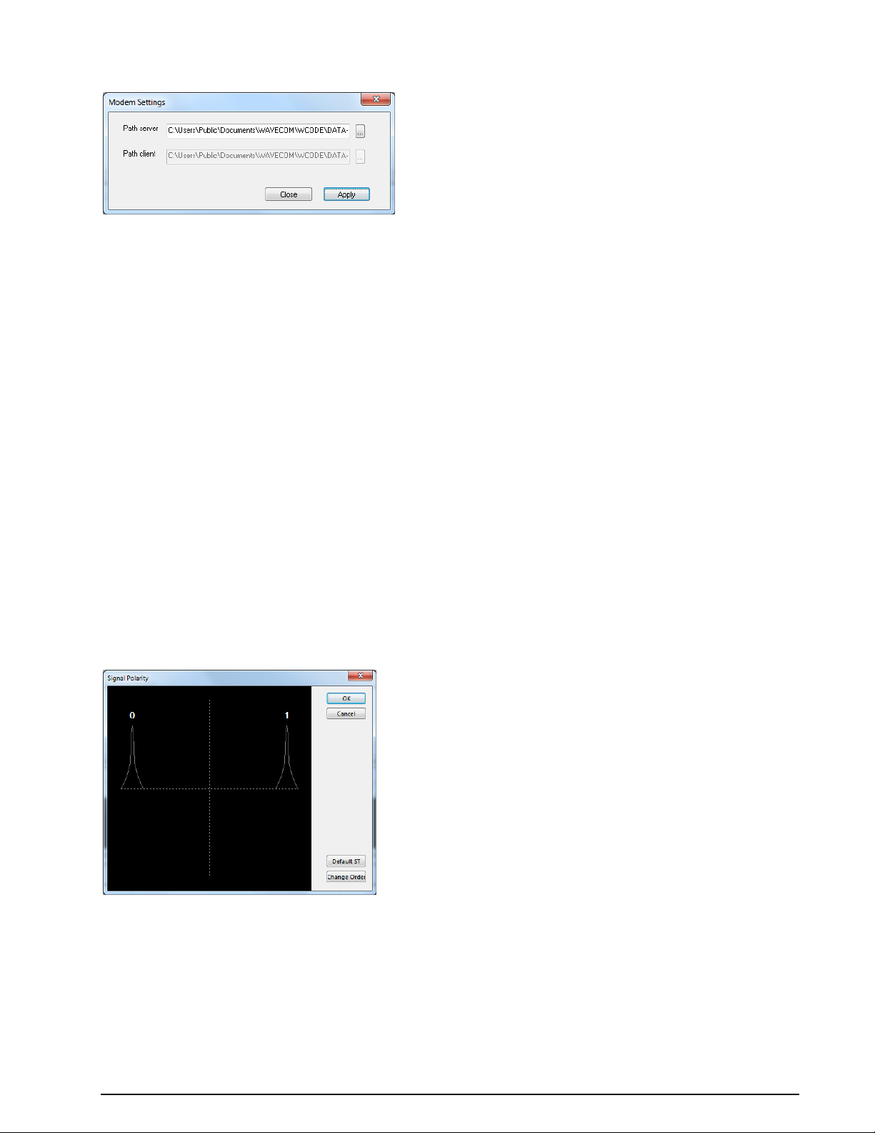
Modem Settings…
For the modem modes additional parameters can be set in the Options | Modem Settings... dialog box.
These settings are:
Path server: Set the Windows directory for the output files on the server.
Path client: Set the Windows directory for the output files on the client computer. This setting is
only enabled on a remote GUI.
MSI
MSI (Multiple Scroll Inhibit) is a function which will suppress multiple linefeeds (LF). In addition, a
software generated Line Feed (LF) is inserted when a carriage return is received.
Using this menu item, the function may be separately toggled on and off for the video output.
Using the MSI function has several advantages. During disturbances in reception a carriage return character may be lost – using MSI prevents lines being overwritten and text being lost. It should also be considered that some stations do not transmit carriage returns: in this case the MSI function will automatically
generate the missing carriage return. To clearly divide a message into paragraphs, many carriage returns
are often transmitted.
Resync Mode
This function forces a re-synchronization of the current mode.
Signal Polarity
If you select a FSK or PSK demodulator in Bitstream Output or Autocorrelation mode, then signal polarity definition is available.
Pressing Change Order will reverse the polarity of the signal and pressing Default ST will restore the default value.
Symbol Definition
If you select a PSK demodulator in Bitstream Output or Autocorrelation mode, then a symbol definition is available.
WAVECOM Decoder W74PC, W-PCI/e, W-CODE, W-CLOUD Manual V9.1.0 First start 43
Page 54
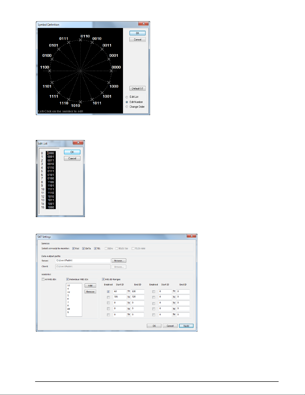
Pressing Change Order will reverse the polarity of the signal and pressing Default ST will restore the default value.
By right-clicking on the display a menu appears.
SAT Settings…
For the SAT Modes, additional parameters can be set in the Options | SAT Settings dialog box.
These settings are:
Service: Select the service to monitor. Choose between:
FAX/DATA/TEL/HSD/TELX_SM/TELX_MM. There are two different possibilities for monitoring
telex:
44 First start WAVECOM Decoder W74PC, W-PCI/e, W-CODE, W-CLOUD Manual V9.1.0
Page 55
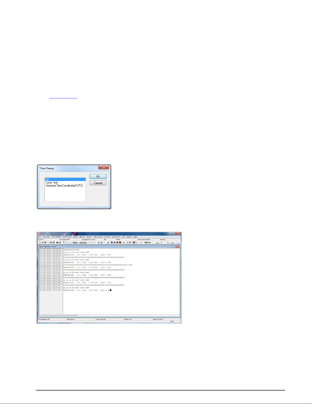
- TELX_SM: Single message monitoring: only the telex of the MES found in the Control Channel
will be recorded.
- TELX_MM: Multi message monitoring, the mode stays on the TDM channel until there are no
more Telex transmissions on this channel.
Server: Set the Windows directory for the output files on the server.
Client: Set the Windows directory for the output files on the client computer. This setting is only
enabled on a remotely-connected GUI.
Watchlist: Click the All MES IDs box, if all MESs must be monitored; leave this box empty if only
specific MESs should be monitored. Enter these MES IDs into the combo box. If ranges of MES IDs
should be monitored, enter and enable each range.
See “SAT System” on page 298.
Toggle
Clicking the Toggle function will immediately switch from the current case to its opposite – i.e., from Letters to Figures or vice-versa. Thus an incorrect case shift caused by a character received in error may be
corrected at once and the proper case restored.
Time Stamp...
Clicking Time stamp offers a selection of different time zones for time stamping text output. Time stamping may also be disabled at a later time through this menu.
To display the time stamp a new window is opened on the left hand side of the screen. When a text line
has been displayed, date and time is displayed in this window. This function is available for all text output
modes.
WAVECOM Decoder W74PC, W-PCI/e, W-CODE, W-CLOUD Manual V9.1.0 First start 45
Page 56

Demodulator Menu
Using the Demodulator menu all parameters for decoding may be edited. In addition to baud rate, the
options and values for mode, shift, center frequency, offset frequency, input and input gain may be manually entered.
The availability of the functions depends on the active mode.
Auto
Click on the Auto button to enable a mode. Shift, center frequency and baud rate is automatically calculated and adjusted. The new value is selected by double-clicking on the preset value or by clicking OK.
Mode...
In the Mode menu the demodulator mode may be selected.
Most HF, VHF or UHF modes feature a pre-selected demodulator mode for optimum performance, but
sometimes different demodulators may be chosen.
AM
Satellite weather charts are transmitted using AM. This demodulator uses the quadrature I/Q demodulation method.
The level displayed by the level indicator corresponds to the AM modulation depth of the signal. The gain
and the amplitude offset may be set using the Demodulator menu.
BPSK
BPSK shifts the carrier phase ±180 degrees. For carrier recovery a Costas loop is used - this is a PLL with
a special phase comparator, which removes the payload data from the PLL loop. The input signal is then
down-converted to base band by mixing the carrier in a complex mixer, and the resulting signal is the data signal.
BPSK is almost exclusively used for satellite data links.
CW
The CW demodulator utilizes a steep, adaptive band pass filter and automatic amplitude control. The AGC
attack time may be adjusted according to the propagation conditions. The filter response may be set to
Slow, Normal or Fast. This demodulator produces high quality CW decoding. It is important to select the
appropriate receiver AGC response (normal or slow).
DSP
The DSP mode utilizes an I/Q demodulator (Hilbert transformation). The received signal is split into an inphase component and a quadrature component. Next, amplitude normalization takes place and the resultant signal is used for the frequency conversion. This method is characterized by a linear relationship between the received frequency and the output voltage of the demodulator.
The DSP demodulator has a good signal-to-noise ratio and yields very good results under most conditions.
DPSK
In differential PSK the absolute carrier phase cannot be used for data recovery as is the case with BPSK
and QPSK. To decode multiphase DPSK (up to 16DPSK) the input signal is mixed with a complex, phase
regulated reference signal. The resulting data reduced signal is then filtered in a low pass filter. The fol-
46 First start WAVECOM Decoder W74PC, W-PCI/e, W-CODE, W-CLOUD Manual V9.1.0
Page 57

lowing phase comparator calculates the phase difference between the signal from the integrator and the
delayed signal.
A variant of DPSK is used almost exclusively when phase modulation is employed on short wave data
links.
DBPSK
Similar to DPSK, but has two phase shifts at ± 180 degrees.
DQPSK
Similar to DPSK, but has four phase shifts at ± 90 and ± 180 degrees.
DTMF
This demodulator handles multi-frequency signals. Filters are switched in on the various frequencies of the
signal and the amplitude is then calculated for each frequency. Next the amplitudes are evaluated. Two
simultaneous tones are demodulated. The SNR is the same as for the mark-space demodulator.
DXPSK
Adaptive DPSK demodulator for PACTOR-II. This demodulator will automatically adapt itself to DBPSK,
DQPSK, D8PSK or D16PSK.
D8PSK
Similar to DPSK, but has eight phase shifts at ±45, ±90, ±135 and ± 180 degrees.
D16PSK
Similar to DPSK, but has sixteen phase shifts at ±22.5, ±45, ±67.5, ±90, ±112.5, ±135, ±157.5 and
±180 degrees.
FFSK and GFSK
Depending on the mode, the FFSK (Fast Frequency Shift Keying) and GFSK (Gaussian Frequency Shift
Keying) demodulator is automatically selected. Basically this demodulator utilizes the I/Q principle (Hilbert). However, filters are adjusted to accommodate the special demands of these modes.
MFSK
This demodulator handles multi-frequency signals. Filters are switched in on the various frequencies of the
signal and the amplitude is then calculated for each frequency. Next the amplitudes are evaluated. Depending on the number of tones used, the filters are configured as phase linear FIR filters or as IIR filters.
The SNR is the same as for the mark-space demodulator. Simultaneous multi-tone decoding (e.g., DTMF)
is not possible with this demodulator.
MS (Mark-Space)
The mark-space demodulator processes the two keying frequencies of a FSK signal. These are fed to two
phase linear FIR filters and the amplitude is then calculated. The mark-space demodulator exhibits an extremely good noise distance and should be used for all FSK modes utilizing a speed of less than 300 Baud.
OQPSK
Carrier recovery is mandatory to demodulate OQPSK. As OQPSK has phase shifts at ±90 degrees, the signal must be squared two times to produce a carrier at four times the original frequency. A PLL recovers
the carrier in frequency and phase with ambiguities at ±90 and ±180 degrees. A complex mixer down
converts the signal to base band and the resulting signal is the data signal. In contrast to QPSK, OQPSK
has only phase steps of ±90 degrees in one step. First the in-phase part is switched, then after half a
symbol duration the quadrature part is switched. The advantage of this process is a smaller amplitude variation.
OQPSK is used almost exclusively for satellite data links.
QPSK
Carrier recovery is mandatory to demodulate QPSK. As QPSK has phase shifts at ±90 and ±180 degrees,
the signal must be squared two times to produce a carrier at four times the original frequency. A PLL recovers the carrier in frequency and phase with ambiguities at ±90 and ±180 degrees. A complex mixer
down converts the signal to base band, and the resulting signal is the data signal.
QPSK is almost exclusively used for satellite data links.
WAVECOM Decoder W74PC, W-PCI/e, W-CODE, W-CLOUD Manual V9.1.0 First start 47
Page 58

SUBTONE
The same as DSP, but the parameters are optimized for low frequencies.
PB Center...
Click on the PB Center menu item to adjust the center frequency of the passband filter.
For more details see “Passband Filter Support” on page 78.
PB Bandwidth...
Click on the PB Bandwidth menu item to adjust the bandwidth of the passband filter.
For more details see “Passband Filter Support” on page 78.
Center...
Click on the Center menu item to adjust the demodulator center frequency within 1 Hz accuracy. For
modes utilizing direct FSK this button is not available: in this case the offset frequency is equal to the effective center frequency.
Shift...
Click on the Shift menu item to adjust the frequency shift in 1Hz steps. In HF modes the range is 50 Hz –
3500 Hz, and in VHF-UHF modes using direct FSK the range is 50 Hz – 16000 Hz.
Baudrate...
Click on the Baudrate menu item to enter a new value. Depending on the mode, the baud rate dialog box
contains preset values which may be directly selected. The new value is selected by double-clicking on the
preset value or clicking on OK.
Polarity...
Click the Polarity menu item to toggle between normal and inverse polarity.
Offset...
Adjusting the offset frequency and the center frequency will adapt the decoder input to a receiver IF output.
The minimum offset frequency resolution available with the decoder is 1 Hz. The effective center frequency is the sum of the offset frequency and the center frequency. The function is similar to the mixing of the
signal frequency and BFO of a receiver.
An exception is the FFSK demodulator for direct frequency modulation: in this case the indicated offset
frequency is equal to the effective center frequency.
An example for an HF receiver and ARQ-E mode:
Receiver IF 455,000 Hz
Offset 453,300 Hz
Center 1700 Hz
The advantage of this method is that the user only needs to know the center frequency.
Another example for a VHF-UHF receiver and POCSAG mode:
Receiver IF 455,000 Hz
Offset 455,000 Hz
Center 0 Hz
In this case the offset frequency is equal to the center frequency.
48 First start WAVECOM Decoder W74PC, W-PCI/e, W-CODE, W-CLOUD Manual V9.1.0
Page 59
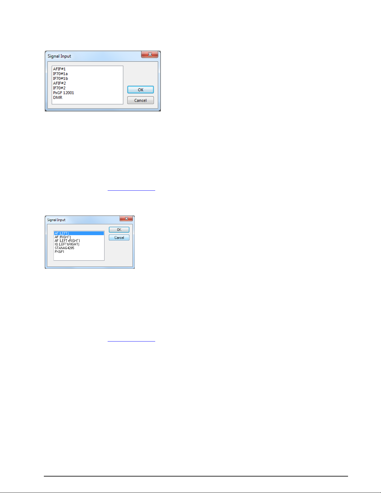
Input...
W-PCI and W-PCIe cards support a number of inputs:
AFIF#1, AFIF#2 are two physically independent inputs. They have a range of 50 Hz–25 MHz.
These inputs should be used when the source is an AF output (line or speaker), or an IF output of
a communication receiver or digital recorder.
IF70#1a, IF70#1b, IF70#2 are IF inputs at 70 MHz with a bandwidth of 35 MHz (52.5 MHz -
87.5 MHz). This IF is common for satellite equipment. The first two (IF70#1a and IF70#1b) and
the third (IF70#2) are of two independent channels.
PXGF 12001 is an example of “Custom Input” with PxGF format.
DMR is an example of “Custom Input” in .wav file format.
For details regarding “Custom Inputs...” see on page 56.
For a soundcard device following inputs are available:
AF(xxx) These inputs are used when you work with the sound card. The frequency range depends
on the sound card specification. You can also apply IF to this input, as long as your signal is within
the supported bandwidth of the selected sound card input.
IQ is used for analogue IQ signals, with the I and Q channels sent to the left and right channel of
the soundcard respectively.
STANAG4285 is an example of “Custom Input” in .wav format.
PXGF1 is an example of “Custom Input” with PxGF format.
For details regarding “Custom Inputs...” see on page 56.
Gain...
When you choose a WAVECOM hardware W-PCI or W-PCIe as device and connect a signal to an input for
the first time, you should use the Automatic Level Setting to adjust the hardware to the input signal level.
WAVECOM Decoder W74PC, W-PCI/e, W-CODE, W-CLOUD Manual V9.1.0 First start 49
Page 60

ALS for W-PCI and W-PCIe device.
Click the “Autoset” button, after the adjustment is finished you can adjust the signal level by moving the
level slider. The gain parameters are saved in the system, i.e., it is not necessary to do ALS when the
same signal is connected to one input.
For other audio devices, e.g., soundcards only manual gain adjustment by the slider is available. The input
gain can be adjusted between 0 and 100% of the nominal input sensitivity of the selected input. When the
gain has been adjusted to the desired level, press OK to save the setting.
The adjustment is valid only for the selected input. The gain setting for each input is separately saved in
the application initialization file.
Gain adjustment should never cause the red bars of the level indicator to be lit.
Gain adjustment for soundcard.
Favorites Menu
The Favorites menu lets the user save and reload a mode and its corresponding settings, i.e., mode, alphabet, center frequency, baud rate etc. The settings are saved in a *.WFV file.
50 First start WAVECOM Decoder W74PC, W-PCI/e, W-CODE, W-CLOUD Manual V9.1.0
Page 61

Open...
Select Open to reload the settings.
Save As...
Select Save to save the settings.
Configuration Menu
In the Configuration menu all general setup functions are available.
WAVECOM Decoder W74PC, W-PCI/e, W-CODE, W-CLOUD Manual V9.1.0 First start 51
Page 62

W-CODE Device…
The first time the decoder application is started with the decoder card installed, the location of the decoder
devices must be set.
In the example above, the W-CODE software is looking for devices in a local computer and remote WCLOUD devices as defined in the “W-CLOUD Networking” section. The process should only take a few seconds.
A Virtual Audio Cable and a soundcard are detected on the local computer. The entry shows the type of
product found as well as the serial number (generated from part of the active MAC address of the computer network interface and a counter).
Important: If you see Error in the device field, there is a problem with the soundcard driver or hardware. Try to reinstall the correct driver.
Windows Vista or Windows 7: Sound card inputs are only detected when a cable or microphone is
plugged in. If you connect a cable, restart the WAVECOM server, otherwise the devices will not be listed in
the WAVECOM software.
Each device is identified by a unique serial number. Thus the application is able to search for devices automatically; this functionality is available for local as well as remote computers - pressing the Connect
button will start the process.
The selected entry is stored in the initialization file (*.INI file) for the card or device and no further entry
is necessary, when the application is restarted. The settings may be changed at any time.
The system can be used in a network configuration. This allows the system to be remotely controlled.
52 First start WAVECOM Decoder W74PC, W-PCI/e, W-CODE, W-CLOUD Manual V9.1.0
Page 63

Font...
Clicking Font opens a configuration window.
Important: Please, note that changing the font and changing the alphabet are two different actions. If
you change the alphabet, then you select a table in a Unicode Font. If you change the font, then you
change the graphical representation (Arial, Courier etc.) of the characters of an alphabet. You may run into problems if you select a non-Unicode font and change the alphabet.
For some types of transmission it will make sense to change the font - this depends on the software that
was used for the transmission.
Temp Files...
Clicking Temp Files opens a configuration window.
You can set the number of lines to be saved to temporary files during a session. These limits allow a user
to leave his computer on for days, while not exhausting hard drive space.
If the temporary files are larger than 50% of free disk space, it will not be possible to save your recording
as a new copy of the temporary file(s) is made when you perform a save operation.
You can select different values for:
Text modes
Fax modes
FSK analysis
Sonagram analysis
Selecting high values allows the user to scroll back over a longer time, but requires more memory and
hard disk space.
WAVECOM Decoder W74PC, W-PCI/e, W-CODE, W-CLOUD Manual V9.1.0 First start 53
Page 64
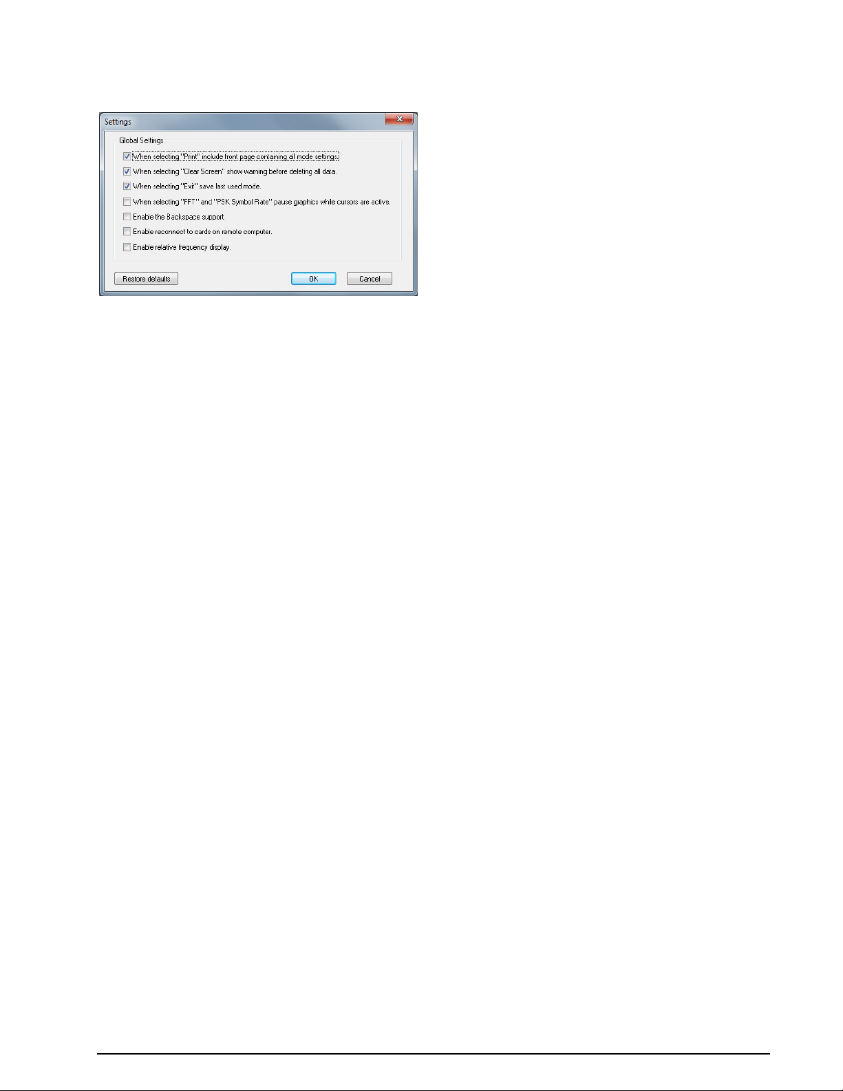
Settings...
Clicking Setttings... opens a configuration window.
You can enable or disable different options, to control the behavior of the application:
When selecting "Print" include front page containing all mode settings. Enable or disable
the printing of a status page with all mode settings if you use the Print command.
When selecting "Clear Screen" show warning before deleting all data. Enable or disable
the display of a warning window before the screen is cleared when you use the Clear Screen
command.
When selecting "Exit" save last mode. Enable or disable storing of settings from the last
mode. If enabled, the decoder will start again in the latest mode used.
When selecting "FFT" and "PSK Symbol Rate" pause graphics while cursors are active.
Enable or disable the automatic freezing of the graphic as long as the cursors are displayed.
Enable the Backspace support. Sometimes in modes like PSK-31, the operator is sending back-
space characters. If backspace support is enabled, backspace will work as for an ordinary terminal
program.
Enable reconnect to cards on remote computer. Enable or disable the GUI to reconnect to a
card on a remote computer. If enabled, the decoder will reconnect to the card on the remote computer.
Enable relative frequency display. You can select if, in the FFT, sonagram etc displays, the “re-
al frequency” (center frequency+offset) or the “relative frequency” is displayed.
Receiver and Satellite Settings...
These settings are used for satellite modes and analysis, and give the operator the possibility to configure
receiver or down-converter frequencies, and to select a satellite and receiver type. The receiver or downconverter control interface to be controlled is connected to a serial port of the computer. Receiver center
frequency is preconfigured to 1542 MHz for the L-Band settings and 3544.5 MHz for the C-Band settings.
54 First start WAVECOM Decoder W74PC, W-PCI/e, W-CODE, W-CLOUD Manual V9.1.0
Page 65
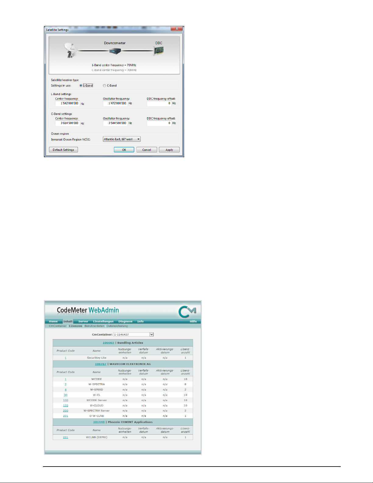
The GUI displays a number of input fields:
Ocean Region. Select the ocean region satellite pointed to by the monitoring antenna.
Oscillator Frequency. Set this parameter to the frequency of the local oscillator used, or set it to
0 if an external converter or mixer is not used.
Frequency Offset. Find out how accurately the receiver sets its frequency. Use the real-time FFT
item in the Analysis DIRECT menu and select a bandwidth of 24 kHz to find out the frequency
offset of the receiver. Adjust the receiver to the NCSC frequency of the appropriate ocean region.
Following this, the NCSC signal should be centered exactly in the FFT display. The adjustment applied to centre the NCSC signal is the offset (make it accurate to 500 Hz or less).
L Band and C-Band Center Frequency. Exact value of the L or C-band frequency that is con-
verted to 70.000 MHz.
License...
When License… is clicked, W-CODE displays the CodeMeter Webadmin page.
WAVECOM Decoder W74PC, W-PCI/e, W-CODE, W-CLOUD Manual V9.1.0 First start 55
Page 66
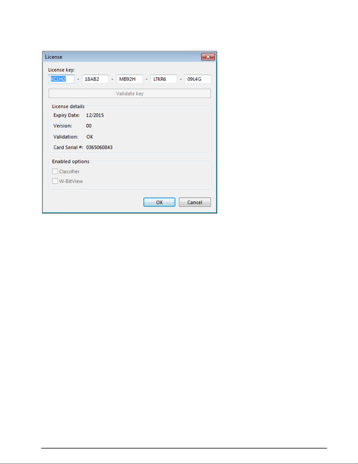
User can choose the tab “Content -> License” to view the license available on the PC.
For Wavecom hardware decoders W-PCI, W-PCIe and W74PC a dialog window opens for the user to input
a 25 alpha-numeric key. The key will be checked with the card serial no. and the software version.
Custom Inputs...
To add a customer defined Input, all other decoder windows must be closed. The number of custom inputs
is limited to 16.
Streaming and custom inputs belong together. A new custom input has to be defined before streaming can
be used to acquire a specific data stream for decoding. At the moment, streaming can be defined for
TCP/IP data, sound card devices (real or virtual) and for .WAV-files. If a custom input is selected as the
input source, the data stream is read from the specific input.
For defining, editing and deleting a custom input, the dialog Custom Inputs is used. The properties of
the custom input are stored in a XML file. The defined custom inputs are selectable like any other input
sources.
56 First start WAVECOM Decoder W74PC, W-PCI/e, W-CODE, W-CLOUD Manual V9.1.0
Page 67
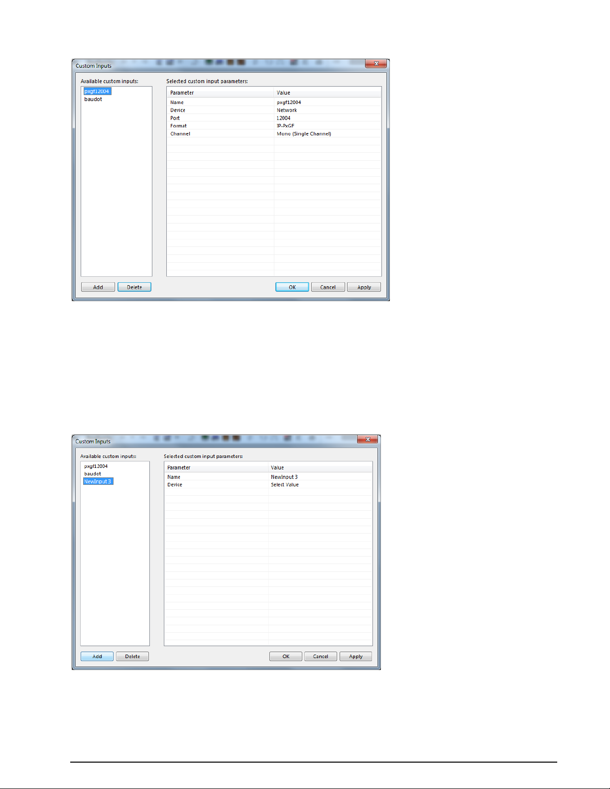
In the screen shot below two user-defined inputs appear.
In the left table, the user defined custom inputs are listed.
In the right table, the parameters of the currently selected custom input are displayed. The Pa-
rameter column contains the names of the parameters, and the Value column shows the related
parameter values.
The Add button is used to create a new custom input. The Apply button saves the parameter set-
tings of a newly created or an edited custom input. Pressing the Delete button removes a selected
custom input.
The following picture shows the Custom Inputs dialog after pressing the Add button.
The Input Name can be edited in the right table by typing a new name into the Value field if desired.
Next, the device type has to be specified. File, Network or Soundcard (for W-PCI, W-PCIe, W74PC and
W61PC hardware decoders) can be chosen from the list box that appears by clicking on the Choose a de-
vice type.
WAVECOM Decoder W74PC, W-PCI/e, W-CODE, W-CLOUD Manual V9.1.0 First start 57
Page 68
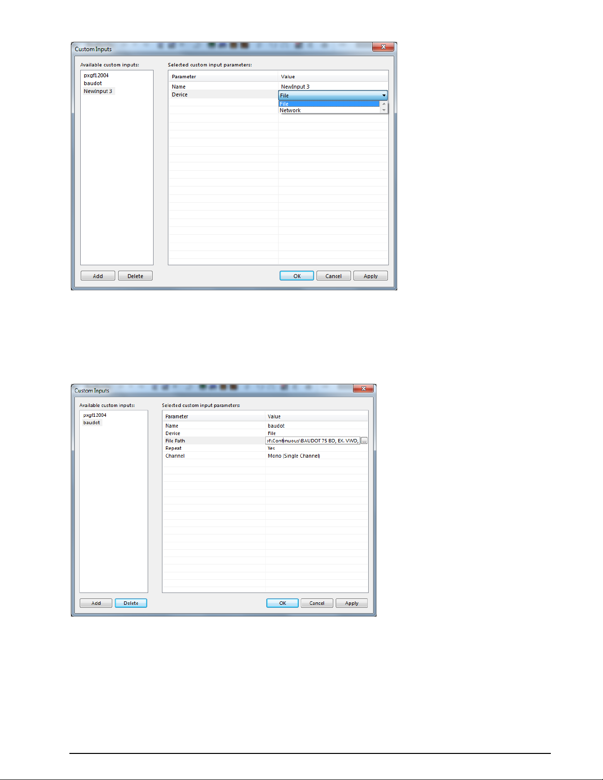
Add a new WAV-File Custom Input
Select the Configuration | Custom Inputs... menu entry to open the configuration dialog for the custom
inputs.
To use a WAV-File as signal input source, the following parameters have to be set via the Custom Inputs
dialog:
58 First start WAVECOM Decoder W74PC, W-PCI/e, W-CODE, W-CLOUD Manual V9.1.0
Page 69
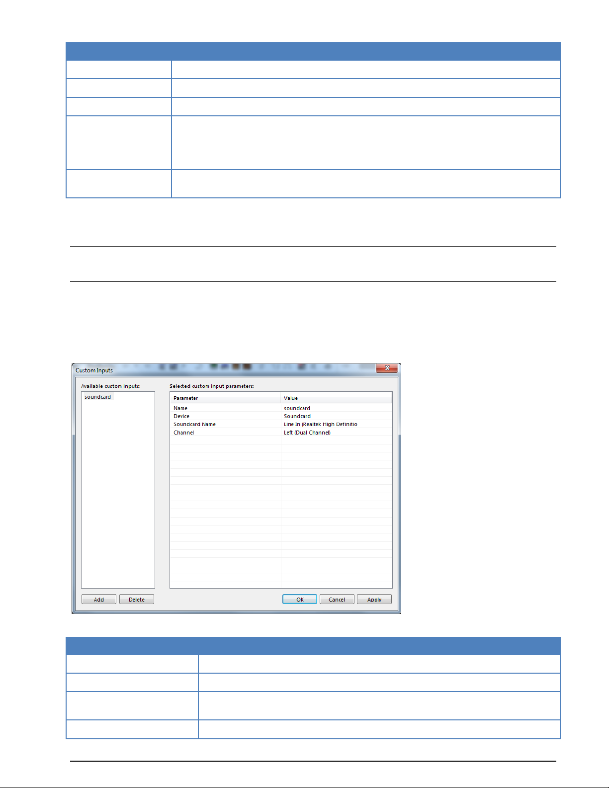
File Input Parameter
Value
Input Name
The name of the custom input
Device
Select File in the list
File Path
The path to the specific WAV-file has to be specified
Channel
In the list box the channel(s) to be used are displayed: Mono, Left, Right, Left + Right
(PCM) and Left & Righe (IQ).
If you start by entering the filename, then the file is analyzed and the correct settings are
automatically selected
Play Continuous
Indicates if the files are played in repeat mode. Select On to switch on the repeat mode or
Off to switch off the repeat mode
Soundcard Input Parameter
Value
Input Name
The name of the custom input
Device
Select Soundcard in the list
Name
The names of all soundcards installed on the computer are displayed in a list box.
Select one soundcard
Channel
In the list box the channel(s) to be used are displayed: Mono, Left, Right, Left +
The file can be selected from any available directory on the LAN. The specified WAV-file is copied to the
Data-Input directory (on the computer hosting the decoder) and stored under the name
<SerialNumberOfW[xx]Card>_<InputName>.wav.
Note: The WAV-file is reloaded each time the Apply button is pressed. The Apply button must also be
used to save the configuration of a new custom input. Pressing the OK button only closes the dialog. The
XML file CustomInputs.xml, located in the Config directory, is updated by pressing the Apply button.
Add a New Sound Card (Real or Virtual) Custom Input
Select the Configuration | Custom Inputs... menu entry to open the configuration dialog for the custom
inputs.
To use a sound card as the signal input source, the following parameters have to be set via the Custom
Inputs dialog:
WAVECOM Decoder W74PC, W-PCI/e, W-CODE, W-CLOUD Manual V9.1.0 First start 59
Page 70
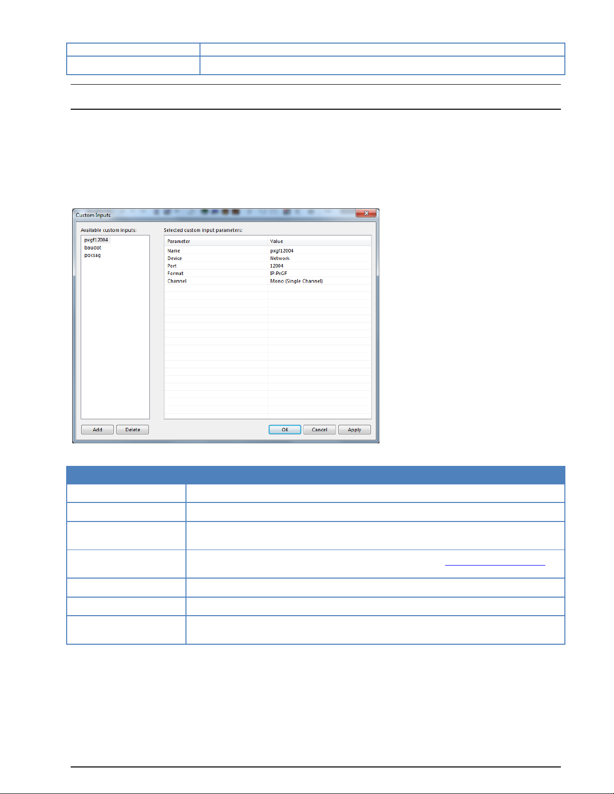
Right (PCM) or Left & Right (IQ)
Sampling Rate [Hz]
The sampling rate is fixed at 48 kHz
Input Parameter
Value
Input Name
The name of the custom input
Device
Select Network in the list
Port number
Enter the a port number. The data source must be configured with the same port number
Format
IP-CONF, IP-PXGF or VITA-49 (for more information, see “WAVECOM Data Formats”
on page 329)
Sampling Rate (Hz)
The sampling rate used by the data source
Number of channels
Number of channels
Channel
In the list box the channel(s) to be used are displayed: Mono, Left, Right, Left +
Right (PCM) and Left & Right (IQ).
Note: If the GUI is running in remote mode, the names of the sound cards installed on the remote com-
puter which hosts the WAVECOM decoder are listed.
Add a new TCP/IP Custom Input
Select the Configuration | Custom Inputs... menu entry to open the configuration dialog for the custom
inputs.
To use a TCP/IP stream as signal input source, the following parameters have to be set via the Custom
Inputs dialog:
Add a new VITA-49 Custom Input
VITA-49 is a standardized stream format which is specified in ANSI/VITA-49.
To use a TCP/IP stream with VITA-49 format as signal input source, the following parameters have to be
set via the Custom Inputs dialog:
60 First start WAVECOM Decoder W74PC, W-PCI/e, W-CODE, W-CLOUD Manual V9.1.0
Page 71
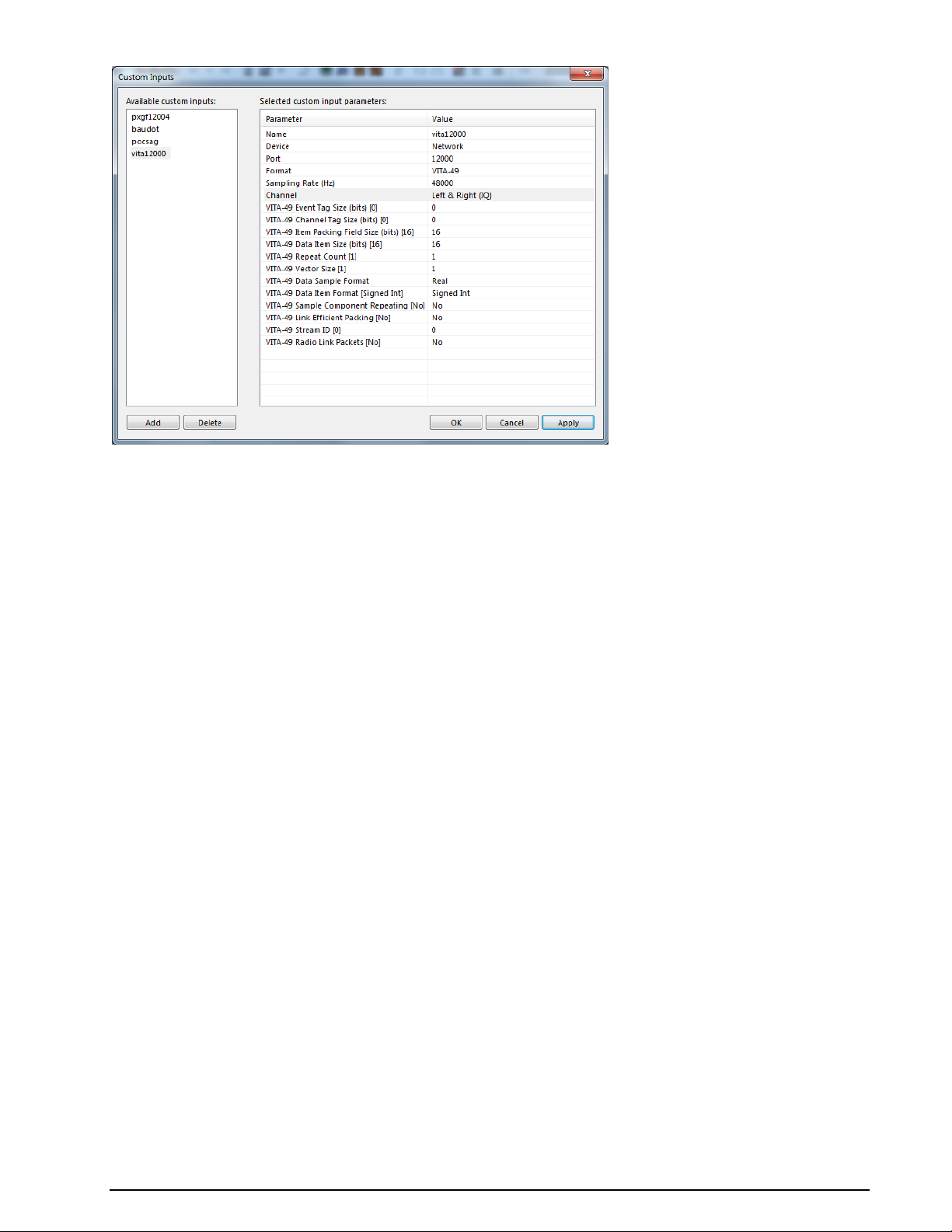
WAVECOM Decoder W74PC, W-PCI/e, W-CODE, W-CLOUD Manual V9.1.0 First start 61
Page 72

Input Parameter
Value
Input Name
The name of the custom input
Device
Select Network in the list
Port number
Enter the a port number. The data source must be configured with the same port number
Format
Select VITA-49
Sampling Rate (Hz)
The sampling rate used by the data source
Channel
In the list box the channel(s) to be used are displayed: Mono, Left, Right, Left +
Right (PCM) and Left & Right (IQ).
VITA-49 Event Tag Size
The size (in bits) of the VITA-49 event tag. This parameter is ignored by W-CODE.
VITA-49 Channel Tag
Size
The size (in bits) of the VITA-49 channel tag. This parameter is ignored by W-CODE.
VITA-49 Item Packing
Field Size
The size of the item packing field. This field contains the event tag, the channel tag and
the data item, so the size must be at least (Event Tag Size) + (Channel Tag Size) +
(Data Item Size).
VITA-49 Data Item Size
The size of a data item. The data item contains the actual sample data.
VITA-49 Repeat Count
The repeat count. It is not supported by W-CODE and should be set to 1 as default.
VITA-49 Vector Size
The vector size. W-CODE does not support vectors, so this value should be set to 1 as
default.
VITA-49 Data Sample
Format
VITA-49 supports the following data sample formats:
Real: Real samples. Each sample consists of 1 data item.
Complex Cartesian: Each sample consists of 2 data items, which are the real
and imaginary parts of a complex number.
Complex Polar: Each sample consists of 2 data items, which are the vector
length and the angle of a complex number.
VITA-49 Data Sample
Format
The format of a data item. VITA-49 supports the following data item formats:
Signed Integer
Signed VRT (1-6 bits)
Unsigned Integer
Unsigned VRT (1-6 bits)
IEEE 754 Float (32 bits)
IEEE 754 Double (64 bits)
VRT is a special floating-poiint format of VITA-49, using 1 to 6 bits for the exponent and
the rest for the mantissa. Using VRT instead of one of the IEEE formats can reduce the
amount of TCP/IP data stream, and save streaming bandwidth.
VITA-49 Sample Component Repeating
Sample Component Repeating. Not supported by W-CODE.
VITA-49 Link Efficient
Packing
This flag decides if data items should be packed to reduce the data size in some cases.
VITA-49 Stream ID
The VITA-49 stream id. Stream IDs are accepted but ignored. No filtering is done.
VITA-49 Radio Link
Packets
Enables the use of VITA-49.1 packets. Those packets, in addition to normal packets,
contain a unique identifier at the beginning and also support a CRC. This makes a VITA49 link much more robust.
Note: The VITA-49 parameters are default values. If a matching context packet is received that contains a
data stream format description, those values are overwritten by that context packet.
62 First start WAVECOM Decoder W74PC, W-PCI/e, W-CODE, W-CLOUD Manual V9.1.0
Page 73
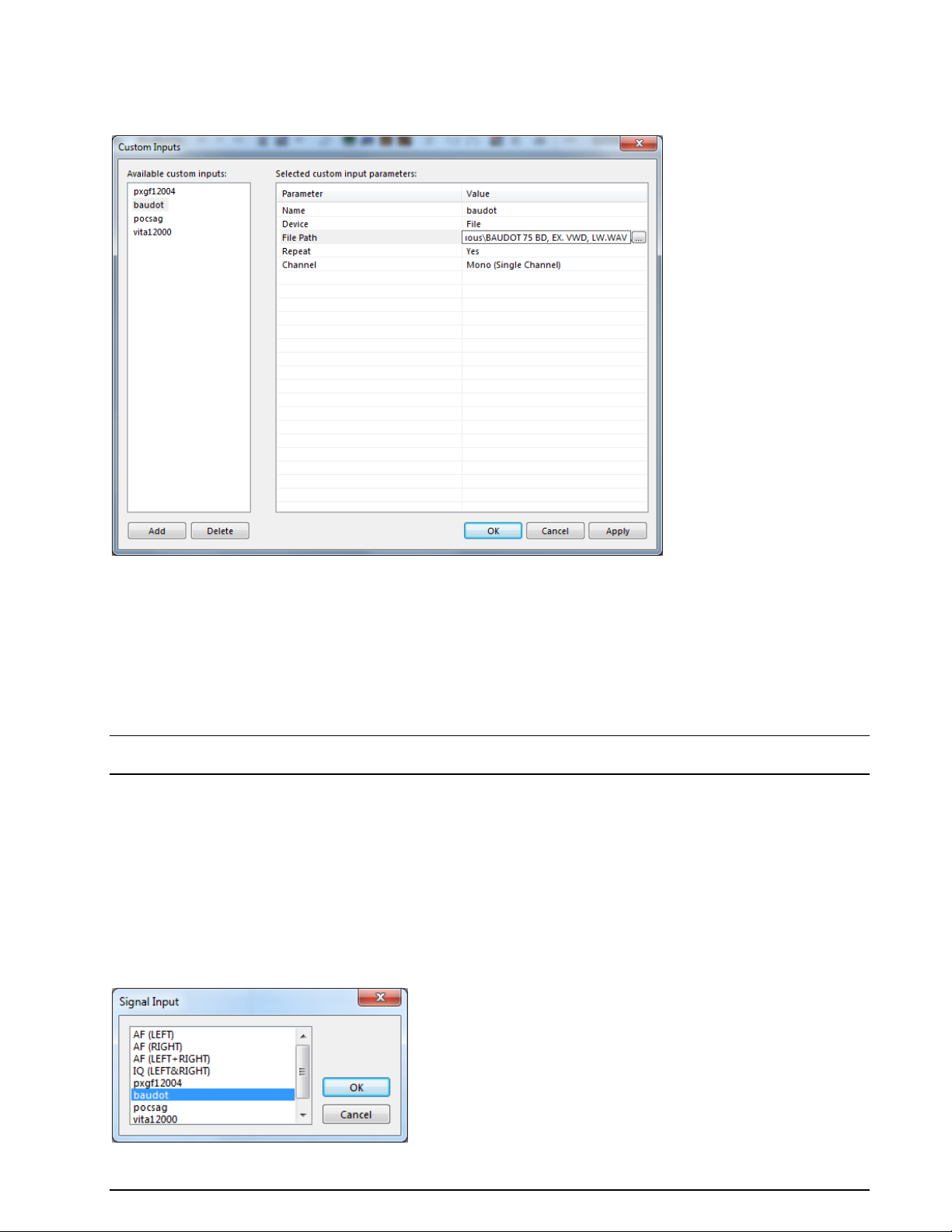
Edit a Custom Input
Select the custom input from the input list on the left in the Custom Inputs dialog. For instance, select
the baudot entry, which is a file input.
Now it is possible to modify the parameter values in the parameter table on the right.
For instance, the Input Name or the Channel parameter value can be modified.
Even the Device value can be changed from File to Network. By changing the device the new devicerelated parameters will appear in the parameter list and the parameters of the old device will disappear.
By pressing the Apply button, the changes will be saved for the specific custom input.
The XML file CustomInputs.xml, located in the Config directory, is updated by pressing the Apply button.
Important: After modifying custom input parameters, press the Apply button; otherwise the changes will
be lost.
Delete a Custom Input
Select the custom input to delete in the Input list (left table) and press the Delete button. This will remove the custom input from the XML file CustomInputs.xml, located in the Config directory.
Selecting a Custom Input
The user defined custom inputs can be selected via the Signal Input dialog. The dialog can be opened via
the Demodulator menu’s entry Input... or by double-clicking the Input status bar field at the right bottom of the GUI.
The screen shot below shows the Signal Input dialog including four user defined custom inputs at the
end of the list.
WAVECOM Decoder W74PC, W-PCI/e, W-CODE, W-CLOUD Manual V9.1.0 First start 63
Page 74

Custom Alphabets…
Custom defined alphabets are also available. This feature allows the user to add alphabets of his own creation that have not been defined by WAVECOM, and to add variants of existing alphabets.
Only 5-bit alphabets are accommodated, and the number of custom alphabets is limited to 16.
The Custom Alphabets… dialog box displays a number of input fields:
Clicking Save As… opens a dialog box, in which to enter a name for the newly created translation
table. Press OK to close the dialog box and save the new translation table. The translation table
contains the actual values set in the Alphabet Translation Table dialog. The name of the new
table appears in the Alphabet combo box and a new .xml file with the name of the table is created containing the table data.
Pressing Save stores the current dialog settings to the translation table that is active as shown in
the Alphabet combo box. The data is stored in the related .xml file.
Clicking Delete deletes the active translation table.
Pressing Undo will replace the new, user selected values in the dialog box with the values stored
for the current alphabet.
The Update List is used to add the user created alphabets to the list of alphabets. By pressing the
Update List button, the Alphabet directory is searched for .xml files related to new alphabet. If a
new one is found the list and the Alphabet combo box are updated.
The Alphabet combo box shows the names of all translation tables. By selecting an entry the
stored data for the specific translation table are displayed. Note that the most recent changes to
the current alphabet are not saved until Save is pressed.
Select the font that is used to display the translation tables by pressing Font.
The Alphabet list control (left list) displays the characters defined for the current alphabet. The
first column shows the position index in the alphabet for the characters. The second column (Current) shows the currently defined value of the character at the selected position. The third column
(New) shows the user defined character value. By pressing the Save button, the Current value
becomes the New value.
The Font list control (right list) displays all the characters defined in the selected font. The first
column shows the decimal or hex character value. The second column (Symbol) shows the character. Selected characters are copied to the selected rows in the Alphabet list by pressing the Ar-
row () button.
Using the Writing Direction radio buttons, a LeftToRight or RightToLeft output direction of the
decoded text may be selected
64 First start WAVECOM Decoder W74PC, W-PCI/e, W-CODE, W-CLOUD Manual V9.1.0
Page 75
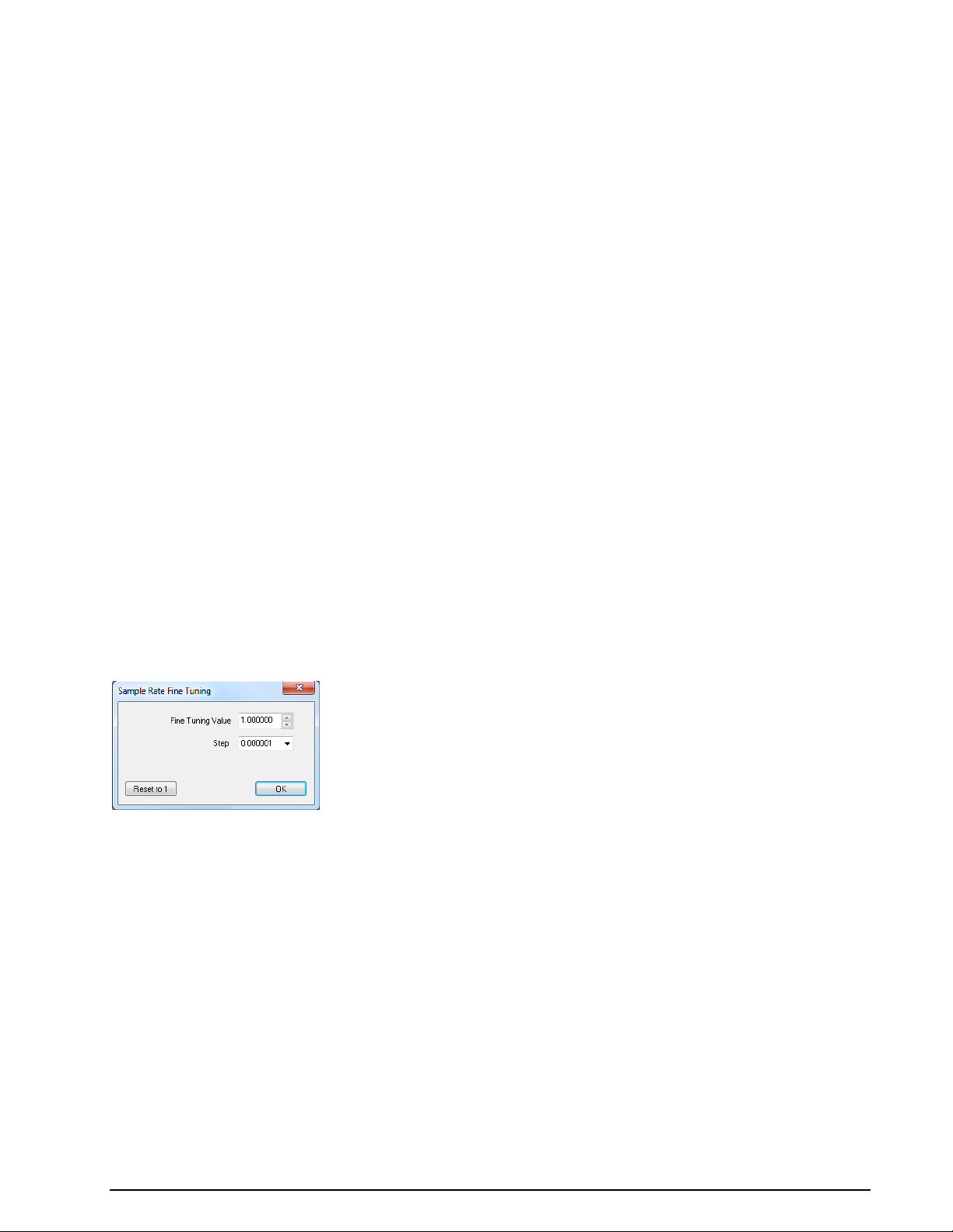
The System combo list is used to set the length of the codeword for a user defined alphabet. The
present version allows only 5-bit alphabets.
Click Transparent to select if control characters are to be displayed in the decoded text.
Depending on which radio button, i.e., Letters, Figures or Third, is selected, the letters, figures
or third shift control characters of the current 5-bit custom alphabet are displayed in the list control.
The Control Characters combo box contains the control characters that can be added to an al-
phabet, i.e., the Letters Shift, Figures Shift, Third Shift, Unperforated Tape, Space,
Linefeed and Carriage Return characters. Select a character, then press the Arrow () button
to copy the selected character to the selected row in the custom Alphabet list.
The Arrow () button is used to move characters to the translation table. Press this button to
copy the selected character in the Font table, or the selected entry in the Control Characters
combo box to the selected position in the Alphabet table.
The Find button and the edit box to the left of the button are used to find a character (decimal or
hex value) in the Alphabet or Font table.
Press Reset to replace all character values in the custom Alphabet list with ‘0’ .
Press Refresh to reload all characters of the current font and update the display. This feature is
useful when the font has been changed.
Pressing Hex View to display the hex value for all characters; otherwise, decimal values are used.
When Show All is enabled, the positions of undefined characters are displayed in the Font char-
acter table.
Press the OK button to close the window. Recent changes are not saved - if the latest changes
have to be saved, press the Save button before pressing OK.
SR Fine Tuning
Sound card sampling frequency accuracy is much more critical for sophisticated digital modes compared to
the simple BAUDOT or SITOR modes. The built-in SR Fine Tuning feature can be used to correct errors
that are introduced by an inaccurate soundcard sampling frequency (the tolerance of soundcards can be a
few hundred parts per million).
SR Calibration
To check the error of you soundcard, use analysis software that is able to calculate the deviation of the
sample rate in ppm. Try to avoid sound cards that are completely out of tolerance.
When W-CODE uses low-cost sound cards as a signal source, sampling frequency errors will most likely
occur. For commonly available sound cards, the sampling frequency may vary up to one percent of the
nominal value. This behavior prevents decoding or introduces additional errors. Complex signals like the
MIL-Standard and STANAG waveforms are heavily affected.
In previous versions of W-CODE the “SR Fine Tuning” feature was used to correct the sampling rate, but
adjusting the rate was very difficult due to a substantial time lag between the adjustment taking place and
the display being updated. To remedy this problem, a new feature has been introduced under “Configura-
tion | SR Calibration”. The new feature utilizes an AM demodulator, which demodulates the pulses of a
reference signal - the output, which resembles a fax image, is displayed in a calibration window. The degree and the direction of slanting of vertical lines are a measure of the amount and the sign of the deviation between the sound card sampling frequency and the reference signal. The values are stored and used
for all future decoding.
Signal thresholds can be set with a tunable band pass filter, which may be placed anywhere in the spectrum with the desired bandwidth. The settings affect the blurring of pulse edges.
WAVECOM Decoder W74PC, W-PCI/e, W-CODE, W-CLOUD Manual V9.1.0 First start 65
Page 76

Reference signals which may be used include weather fax transmissions and time signals, e.g., CHU,
DCF77, MSF, HBG etc. For instance, CHU transmits a short tone pulse every second. If the band pass filter
is tuned to the frequency of this tone, a straight, vertical line will be visible if the sampling rate of the
sound card is correct. If the line is slanted to either side the sampling rate is offset. To adjust the sampling rate, use “Options | Fine Tune” until the vertical line representing the reference signal is straight.
Example: CHU signal
First adjust the center frequency and the bandpass filter settings. You will notice that the vertical lines are
skewed.
Press “Options | Fine Tune…” and use the slider to adjust the vertical lines so they become perpendicular
to the time axis of the calibration window.
Note: The full range of the “Fine Tune” process is 0.1% deviation. For deviations larger than this use “Fine
Tune” repeatedly until the desired effect has been achieved.
If you succeeded in correcting the sampling rate, i.e., the vertical lines have been straightened and are
perpendicular to the time axis, press “OK” to save the measured value.
66 First start WAVECOM Decoder W74PC, W-PCI/e, W-CODE, W-CLOUD Manual V9.1.0
Page 77

As the sampling rate calibration feature utilizes an AM demodulator, input level should be as high as pos-
sible, resulting in a high level of contrast which facilitates the adjustments. If necessary use the “Demodu-
lator” menu to adjust the AM gain and offset.
These two functionalities (“SR Fine Tuning” and “SR Calibration”) are not available when W-PCI or W-PCIe
is used.
View Menu
In the View menu the visibility of each individual status and indicator element may be enabled or disabled. A checkmark indicates that the element is enabled. A disabled element is not deleted, but may be
made visible at any time.
Window Menu
Using the Window menu new output windows may be opened and organized.
Help Menu
For context sensitive help on a menu item, use F1 on the item.
WAVECOM Decoder W74PC, W-PCI/e, W-CODE, W-CLOUD Manual V9.1.0 First start 67
Page 78

Mode Selector
Analysis Selector
Back - go to last decoding or analysis mode
History - select one of the last decoding or analysis modes from this drop down menu.
Contents
Selecting Contents opens the online help system.
Help on clicked buttons, menus and windows are then available.
WAVECOM on the Web
Contents access the decoder help file.
www.wavecom.ch links to website of WAVECOM.
About W-CODE
Displays information on software version, build number, and release date for the installed application.
Other GUI Elements
Toolbar
Allows access to file, print and search operations. Most functions on this toolbar are also available from the
File menu.
If the mouse is resting for more than approximately half a second on a button, a label with the name of
the function is displayed (tool tip). In addition a short help text is displayed on the system status bar.
Depending on the active mode, buttons for which the corresponding function is not available are grayed.
WAVECOM Toolbar
The selection of the most important decoder functions is facilitated by toolbar buttons. Operation is identical to the use of the menu bar.
If the mouse is resting for more than approximately half a second on a button, a label with the name of
the function is displayed (tool tip). In addition a short help text is displayed on the system status bar.
Depending on the active mode, buttons for which the corresponding function is not available are grayed.
68 First start WAVECOM Decoder W74PC, W-PCI/e, W-CODE, W-CLOUD Manual V9.1.0
Page 79

Go Forward in the history list after going back in the history list
Classifier
Classifier Code Check
Start/Stop Classifer
FSK Auto Tuning
FSK Analysis
FFT Analysis
Sonagram Analysis
Waterfall Analysis
Resync Mode
Toggle Letter/Figure
Maximize Passband
Media Player/Recorder
Live Voice
W-CLOUD Device Settings, to show traffic statistics of a W-CLOUD device and to enable / disable the
output of signal from a remote W-CLOUD station to the local speaker
Level Indicator
Click on the Gain icon to adjust the input to the correct level. Gain adjustment must never turn on the
red bars of the level indicator.
Spectrum Indicator
The Spectrum Indicator is a tuning tool consisting of a bar graph, increasing frequency from the left to
the right, which displays the frequencies of the incoming signal. For FSK signals the mark and space frequencies are displayed. For PSK signals the carrier is displayed.
Decoder Status Bar
The Status Bar displays decoder status information.
WAVECOM Decoder W74PC, W-PCI/e, W-CODE, W-CLOUD Manual V9.1.0 First start 69
Page 80
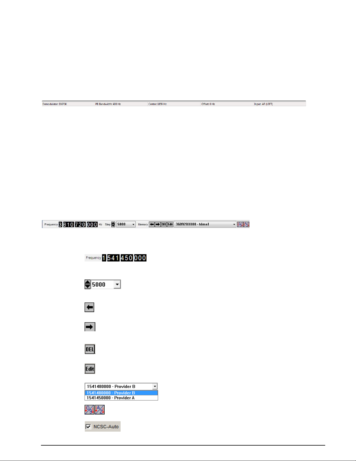
Frequency
User entry field for the real frequency.
In modes with automatic frequency setting the automatically set
frequency is shown.
Step
Spinner to increase or decrease the frequency.
List box to select the frequency step for the spinner.
Memory
Retrieve a frequency from the selected memory entry.
Store the current frequency to memory. You will be prompted for
a name. The current frequency will be replaced by the new frequency.
Delete the contents of the selected memory position.
Edit the name of the memory entry.
List box containing memory entries.
Sort buttons for numerical or alphabetical sort of the list box entries.
NCSC-Auto
Only available in SAT-C-TDM mode. Please, refer the manual section on SAT-C-TDM.
Double-Clicking on Status Bar Fields
Double-clicking the status bar fields will open the corresponding dialog box. This facilitates the use of the
decoder software.
A double-click on the shift field, baud rate field, frequency shift field, etc. of the demodulator status bar
opens the corresponding dialog box.
Selecting a field will not terminate the active mode. As far as possible, value changes will be implemented
immediately, without the interruption of data acquisition.
Demodulator Status Bar
The Demodulator Status Bar displays information about the status of the DSP demodulator.
Double-Clicking on Status Bar Fields
Double-clicking various status bar fields will activate the corresponding dialog boxes. This facilitates the
use of the decoder software.
A double-click on the shift field, baud rate field, frequency shift field etc. of the demodulator status bar
opens the corresponding dialog boxes.
Selecting a field will not terminate the active mode. As far as possible changed values will be immediately
used without interrupting data acquisition.
SAT Frequency Tuning Bar
The SAT Frequency Tuning Bar simplifies frequency selection for the satellite modes. In Receiver and
Satellite Settings the user has the ability to store the center frequency of the down converter.
The SAT Frequency Tuning Bar box displays a number of inputs and controls:
70 First start WAVECOM Decoder W74PC, W-PCI/e, W-CODE, W-CLOUD Manual V9.1.0
Page 81
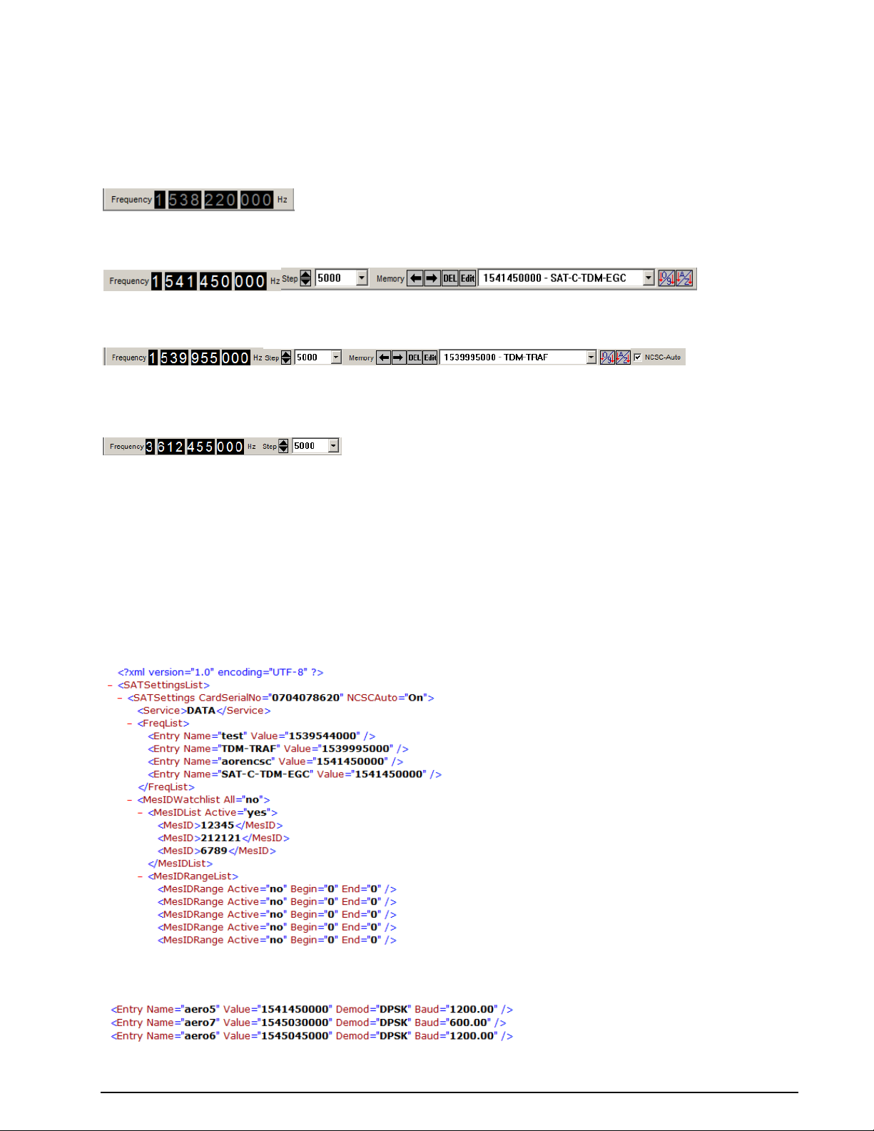
The SAT Frequency Tuning Bar display elements are mode dependent.
There are three different variations of the frequency bar:
SAT-B, SAT-M, SAT-mM
Display of the real frequency. Direct tuning is disabled.
SAT-B-C-TFC, SAT-AERO-P, SAT-C-TDM-EGC, SAT-C-TDMA
Display of the real frequency, frequency memory and step. Direct tuning is enabled.
SAT-C-TDM
Display of the real frequency, frequency memory and step. Direct tuning is enabled. NCSC-Auto tuning
can be selected.
Waterfall SAT, FFT SAT, Sonagram SAT
Display of the real frequency and step. Direct tuning is enabled.
The C-band or L-band frequency range depends on the system context set up in the Receiver and Satellite
Settings.
XML Frequency Memories File
All frequencies are stored in XML files c:\Users\Public\Documents\WAVECOM\<Product>\. Each mode has
a XML file containing its corresponding settings. In addition to frequency entries, the watch list, desired
services, NCSC-Auto status (only for SAT-C-TDM) and demodulators used (only for SAT-AERO-P) are
stored in these files.
The illustration below shows an example of a XML file for the SAT-C-TDM mode, including watch list and
memory positions.
For SAT-AERO-P a frequency entry contains the demodulator used on a particular frequency.
WAVECOM Decoder W74PC, W-PCI/e, W-CODE, W-CLOUD Manual V9.1.0 First start 71
Page 82
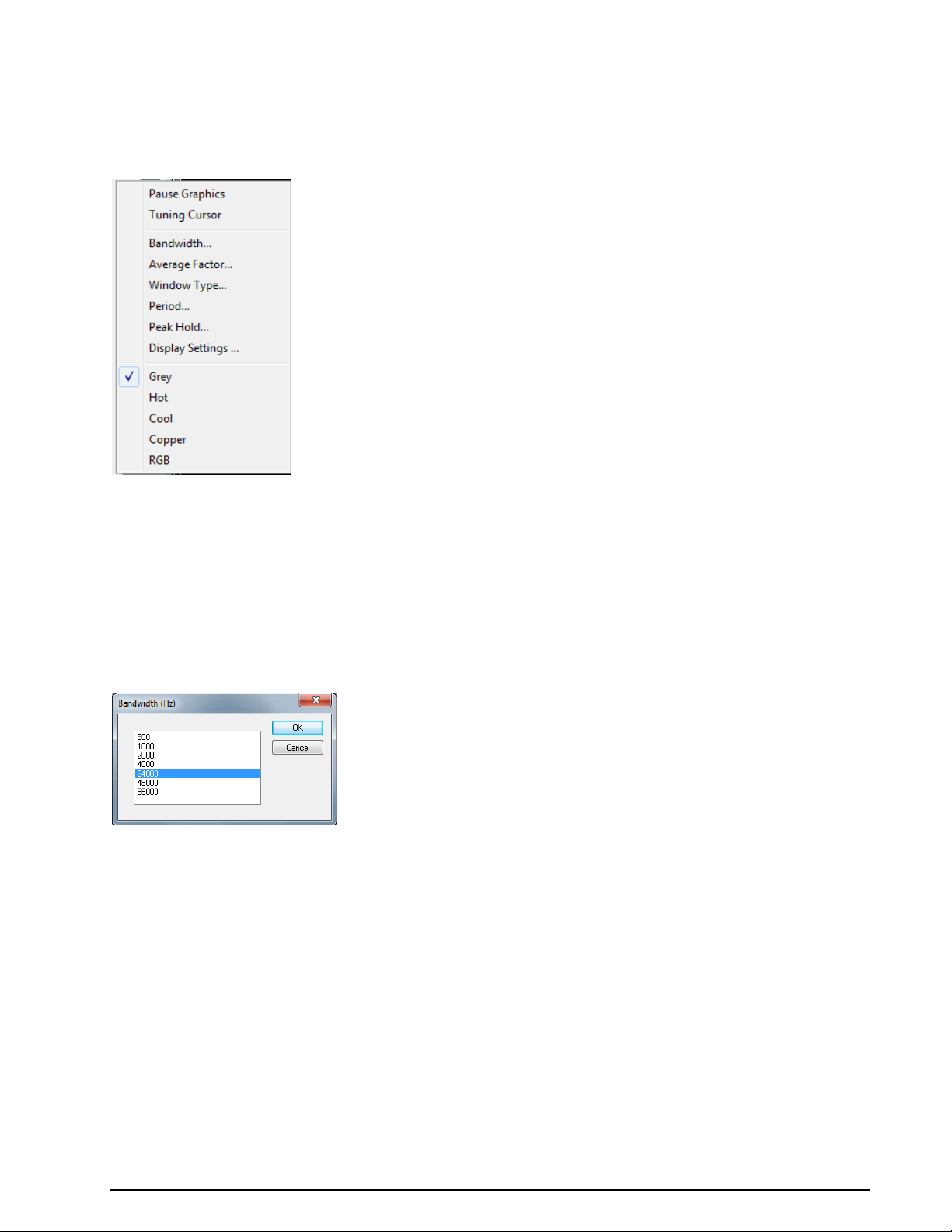
In multi-card systems, each card has its own section in the XML file.
The user may edit these files by hand, however it is recommended to use the SAT Frequency Tuning Bar.
The installation package contains example XML files for each mode.
FFT/Sonagram Context Menu
Pause Graphic
Freeze the FFT or Sonagram Window.
Tuning Cursor
Show the 8 green cursor-group in the FFT or Sonagram Window for tuning (multi-carrier) signals.
Bandwidth...
To select a display bandwidth use Bandwidth from the context menu or double-click on the Bandwidth:
field on the demodulator status bar. For the Tuning Sonagram / FFT bandwidths of 0.5, 1.0, 2.0, and
4.0 kHz are available. For the Analysis FFT/Sonagram bandwidths of 0.5, 1.0, 2.0, 4.0, 24, 48 and 96 kHz
are available.
Average Factor
After choosing an Average Factor from the context menu, the average of up to 64 measurements may
be displayed at each step. A value of "1" turns averaging off. The averaged display of several measurements is very helpful when monitoring MFSK and FDM transmissions or during heavy fading. The averaging function may also be selected by double-clicking the Avg: field in the upper status bar.
Window Type…
Four window functions Rectangle, Hamming, Hanning and Blackman may be selected. The selection of
a window type influences the accuracy of the signal spectrum measurement. Good frequency resolution is
obtained using the rectangular window, however the rectangular window also causes heavy distortion due
to its poor side-lobe suppression characteristics. A window should be chosen according to the user’s requirements; each window type has its own characteristics as listed below.
The user should be aware that changes in the received signal can cause the display of spurious spectral
lines or aliasing ("false" frequency display) in FFT measurements. Depending on the keying frequency and
the magnitude of the frequency shift, the aliased frequencies may even be stronger than the desired signal.
72 First start WAVECOM Decoder W74PC, W-PCI/e, W-CODE, W-CLOUD Manual V9.1.0
Page 83
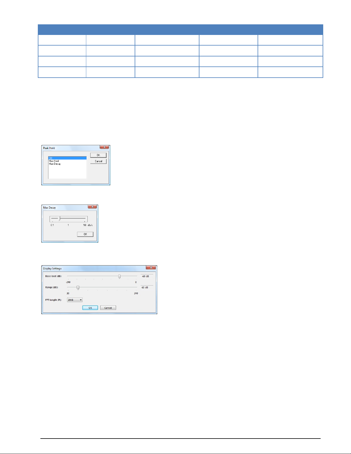
Window Type
Signal Type
Frequency Resolution
Spectral Leakage
Amplitude Accuracy
Blackman
Random
Poor
Best
Poor
Hamming
Random
Good
Fair
Fair
Hanning
Random
Good
Good
Fair
Rectangular
Transient
Best
Poor
Poor
Period...
From the Period menu the time unit per measurement may be selected. The lowest value is 50 ms corre-
sponding to 20 FFT’s/s. For the highest value of 10,000 ms a measurement is done once every 10 seconds.
Peak Hold…
For easy tuning, switch on Peak Hold in the Options menu on. The tone spectrum appears in the FFT
window after a short delay and the frequency range can be changed as required using the cursors as
shown below.
If you select max Decay, then a decay value can be set. This allows to use the peak hold functions during
thunderstorms or if tuning the receiver.
Display Settings…
To configure other parameters of the FFT, select Display Settings.
The sliders "Base level" and "Range" control the dynamics of the FFT. "Base level" sets the minimum level
that is visible in the FFT display. "Range" is the difference between the maximum and the minimum level.
With "FFT length", the number of points used to calculate the FFT can be set. A longer FFT length leads to
increased resolution in the frequency domain. This can be useful in analyzing OFDM signals, where it is also recommended to select a bigger average factor to reduce the noise shown in the FFT.
Color Schemes
Select between Grey, Hot, Cool, Cooper and RGB.
Mode Selector
Full-screen menus are available for modes and analysis tools. Click on the Mode Selector Button in the
toolbar to open this menu. Modes are available in alphabetical order. Click on a mode to start it. From the
top row tabs analysis tools may also be selected.
WAVECOM Decoder W74PC, W-PCI/e, W-CODE, W-CLOUD Manual V9.1.0 First start 73
Page 84
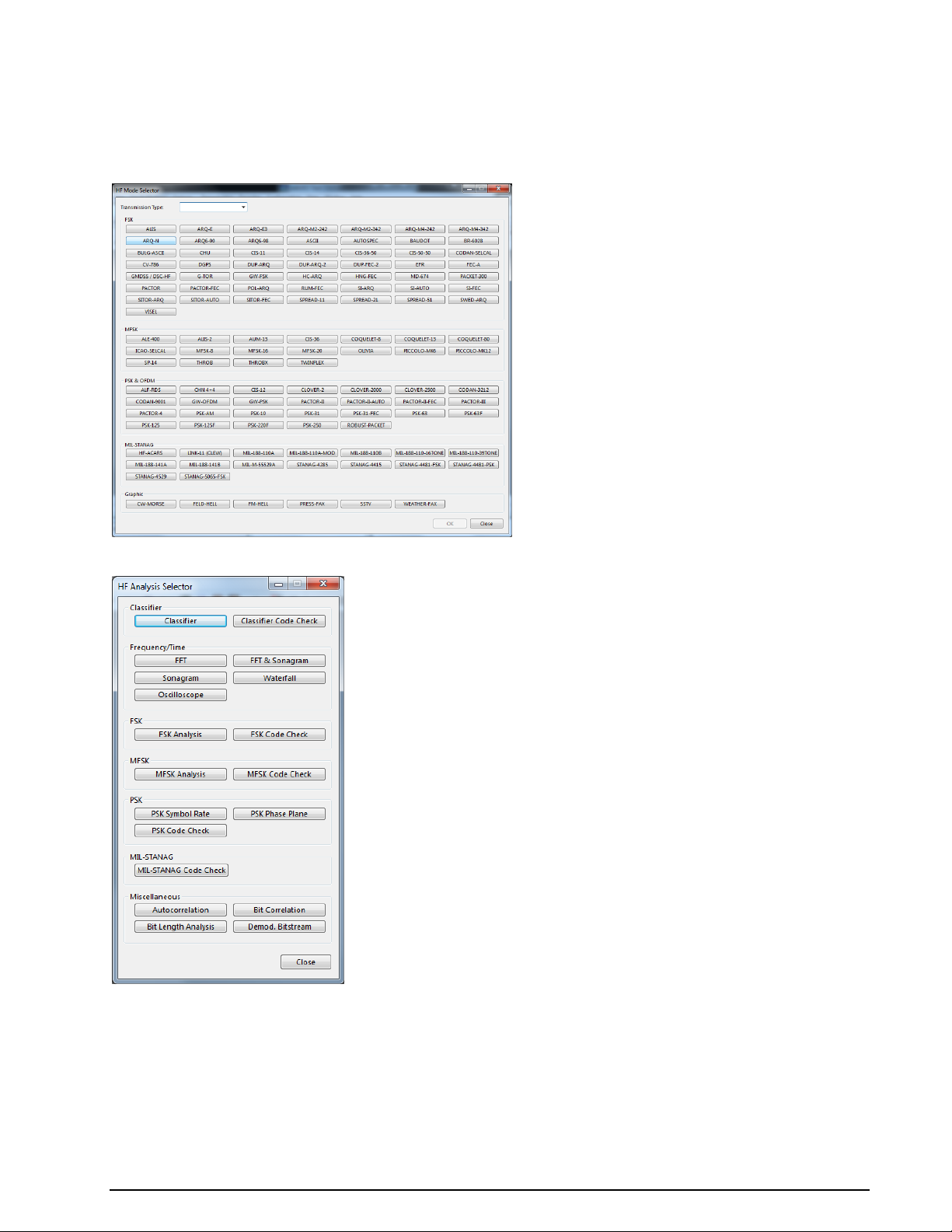
If a mode is already active it will not be terminated or halted by opening the full-screen menu. Click on
Cancel or the Close button to leave the menu.
The descriptions of the operating modes in another section of this manual are arranged in alphabetical order.
HF Mode Selector
HF Analysis Selector
74 First start WAVECOM Decoder W74PC, W-PCI/e, W-CODE, W-CLOUD Manual V9.1.0
Page 85
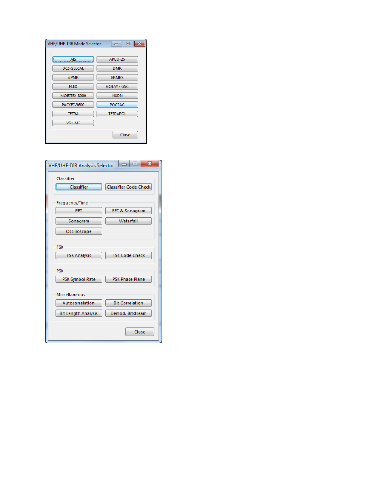
VHF/UHF-DIR Mode Selector
VHF/UHF-DIR Analysis Selector
WAVECOM Decoder W74PC, W-PCI/e, W-CODE, W-CLOUD Manual V9.1.0 First start 75
Page 86
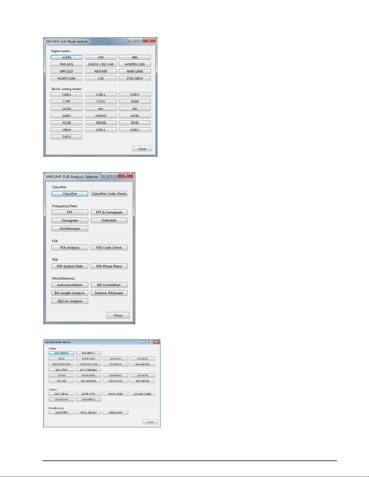
VHF/UHF-SUB Mode Selector
VHF/UHF-SUB Analysis Selector
Satellite Mode Selector
76 First start WAVECOM Decoder W74PC, W-PCI/e, W-CODE, W-CLOUD Manual V9.1.0
Page 87
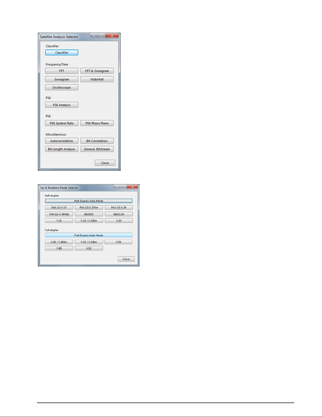
Satellite Analysis Selector
FAX & Modem Mode Selector
WAVECOM Decoder W74PC, W-PCI/e, W-CODE, W-CLOUD Manual V9.1.0 First start 77
Page 88
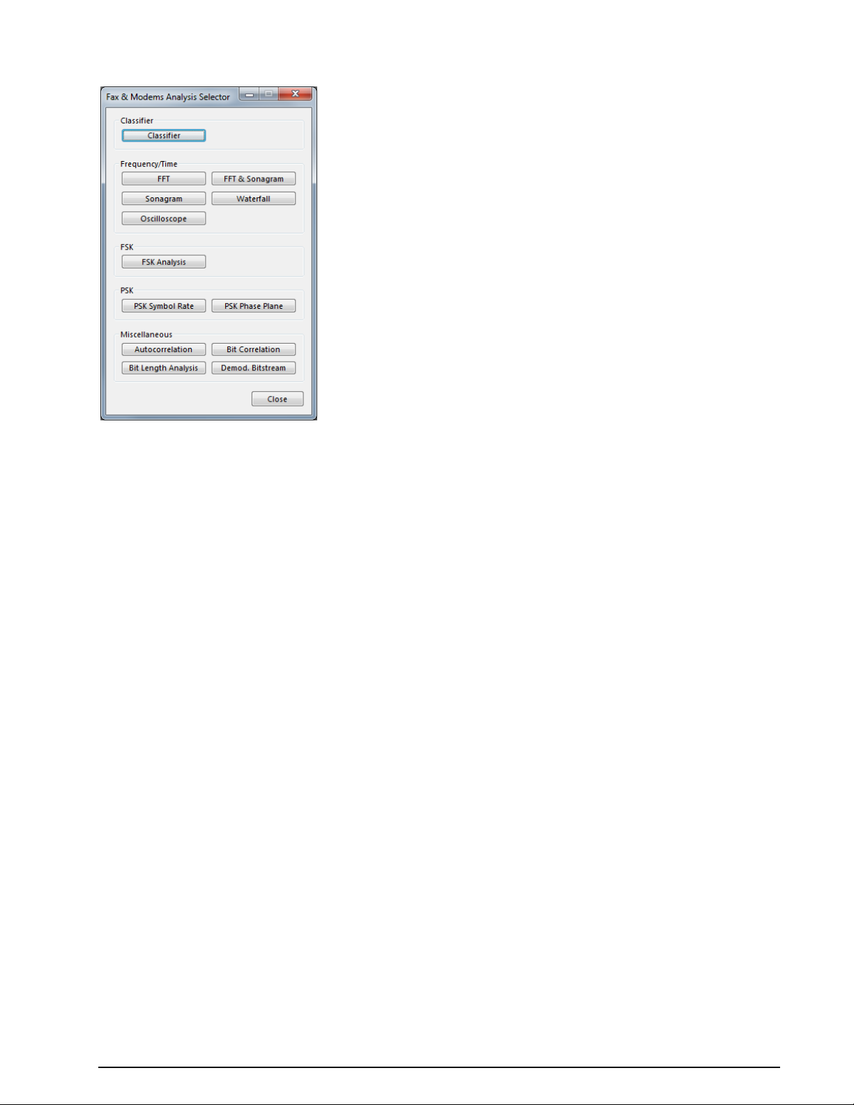
FAX & Modem Analysis Selector
Passband Filter Support
Perfect signal processing (filtering) is essential for best decoding results, which are achieved by using the
correct filters in the receiver. Doing so prevents blocking effects from strong nearby signals. However correctly processed signals may be unavailable, e.g., when a receiver does not offer optimum filters or when
using recorded signals. To overcome these obstacles additional passband filters are included in the
WAVECOM decoders to assist the operator in separating signals within the analyzed frequency spectrum.
In the WAVECOM GUI a passband (PB) tuning bar is placed below the tuning FFT window. If tuning FFT is
not available, as is the case for some modes, the parameters can be set in the Demodulator Menu.
For many modes the parameters PB Center, PB Bandwidth and Center can be individually controlled
(see the table below).
78 First start WAVECOM Decoder W74PC, W-PCI/e, W-CODE, W-CLOUD Manual V9.1.0
Page 89

Item
PB Conf.
Remarks
DSP
+
Freely configurable
AM + Freely configurable
CW + Freely configurable
GFSK
+
PB center frequency controlled from offset frequency setting
FFSK
+
PB center frequency controlled from offset frequency setting
MARK-SPACE
-
PB automatically adjusted depending on center, shift and speed
MFSK
-
Individual tones are filtered and PB automatically adjusted depending on tone spacing, center and speed
DTMF
-
Individual tones are filtered and PB automatically adjusted depending on tone spacing, center and speed
BR6028
-
Preconfigured filters that cannot be changed. The location of the pilot tone can be manually set
BPSK
+
Freely configurable
QPSK
+
Freely configurable
OQPSK
+
Freely configurable
DPSK
-
PB bandwidth automatically adjusted depending on center, shift and
speed. The center frequency can be manually set
DXPSK
-
PB bandwidth automatically adjusted depending on center, shift and
speed. The center frequency can be manually set
DBPSK
-
PB bandwidth automatically adjusted depending on center, shift and
speed. The center frequency can be manually set
DQPSK
-
PB bandwidth automatically adjusted depending on center, shift and
speed. The center frequency can be manually set
D8PSK
-
PB bandwidth automatically adjusted depending on center, shift and
speed. The center frequency can be manually set
D16PSK
-
PB bandwidth automatically adjusted depending on center, shift and
speed. The center frequency can be manually set
IQ + Freely configurable
ANALYSE
+
Freely configurable
FFT - No filtering implemented
TIME
-
No filtering implemented
OFDM
-
No filtering implemented
SUBTONE
-
No filtering implemented
DISCRIMINATOR
-
No filtering implemented
EXT-DEM
-
No filtering implemented
BYPASS
-
No filtering implemented
The PB parameters can be set to maximum bandwidth (switched off) with the Maximize Passband button.
WAVECOM Decoder W74PC, W-PCI/e, W-CODE, W-CLOUD Manual V9.1.0 First start 79
Page 90
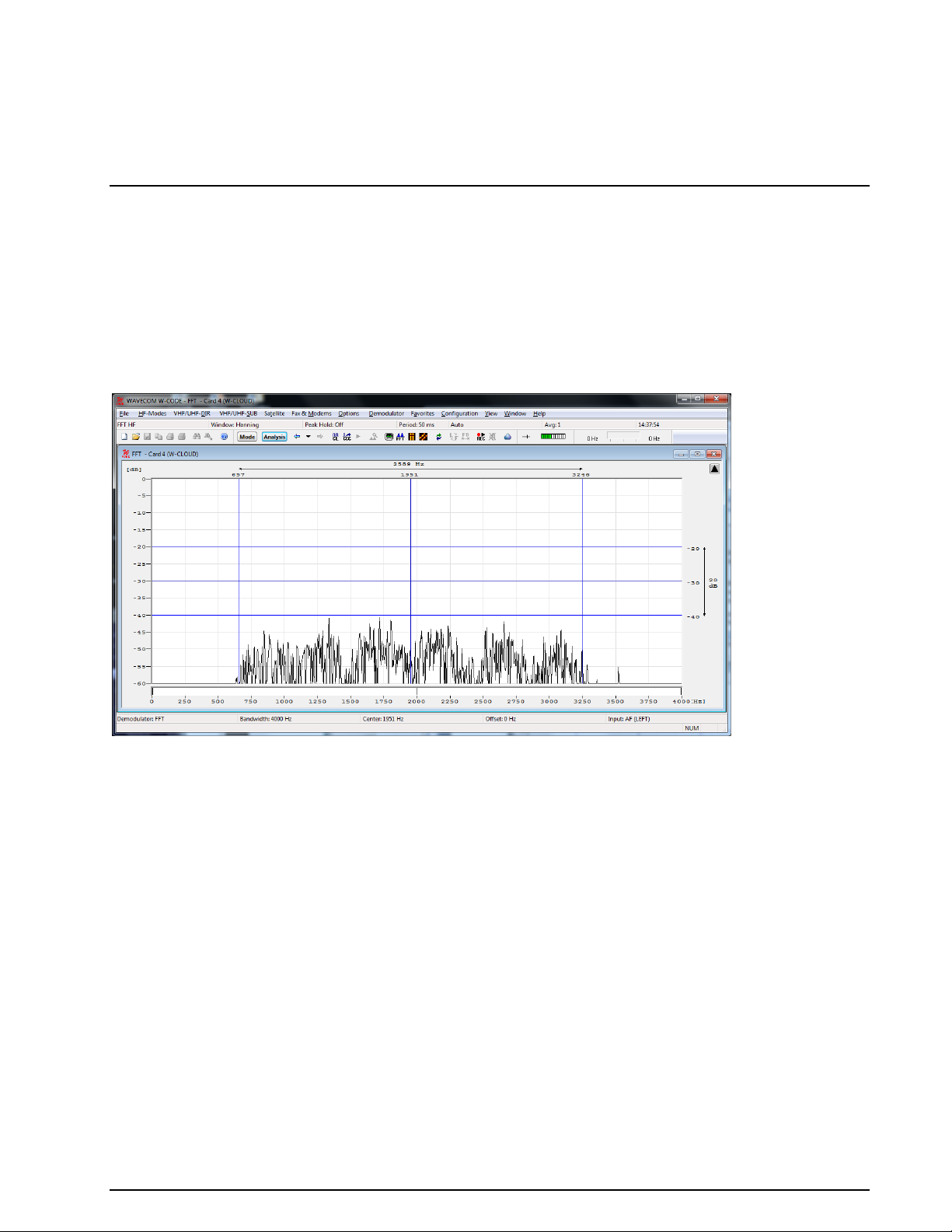
Analysis Tools
FFT
The real-time FFT analysis is a powerful spectrum analysis tool based on Fast Fourier Analysis (FFT), operating in real time with a 4096-point resolution. The signal is digitized, saved and its frequency spectrum
calculated and displayed.
The measurement is started by selecting a bandwidth. The display of the frequency spectrum has a linear
scale and covers a dynamic range of 60 dB. (The internal dynamic range is considerably higher due to the
16 bit A/D converter used, but the configured display resolution performs better in practical use.)
The frame refresh rate averages 10 to 20 pictures per second, allowing even fast signal changes to be displayed. The frame refresh rate is however dependent on the speed of the PC and its video card.
To start the FFT, click on the FFT button or use Analysis | Real-time FFT from one of the menus.
To activate the measurement cursors, click inside the FFT graphics window. The left and right cursors may
be moved around using the mouse. The cursor positions are displayed as absolute frequency values; the
center cursor automatically displays the center value.
To remove the cursors, click on the graphics window again.
When the cursors have been placed in the desired positions they may be moved right or left by moving
the center cursor. By doing this, the measurement of frequency spacing in MFSK and FDM systems is possible.
Adjustment of the Offset Frequency
An FFT spectrum calculation can be done from 0 Hz, up to the selected maximum frequency.
The offset frequency for decoding of VHF/UHF-DIR transmissions e.g., POCSAG, GOLAY/GSC, or ERMES
must be adjusted to the effective center frequency of the signal, e.g., 455 kHz.
A bandwidth of 24 kHz from 455 kHz to 479 kHz is sufficient for the measurement range of the FFT.
therefore the offset frequency must be offset to half of the bandwidth. The offset frequency adjustment is
calculated as the IF output frequency (455 kHz) minus half of the selected FFT bandwidth (24/2 kHz) =
Offset (443 kHz). The measurement range is now 443 kHz - 467 kHz.
For the 455 kHz receiver IF output of a shortwave receiver (e.g., HF-1000), the offset frequency is first
adjusted to 453.3 kHz to obtain the standard center frequency of 1,700 Hz. The HF-1000 BFO must now
be adjusted to 1,700 Hz.
80 Analysis Tools WAVECOM Decoder W74PC, W-PCI/e, W-CODE, W-CLOUD Manual V9.1.0
Page 91
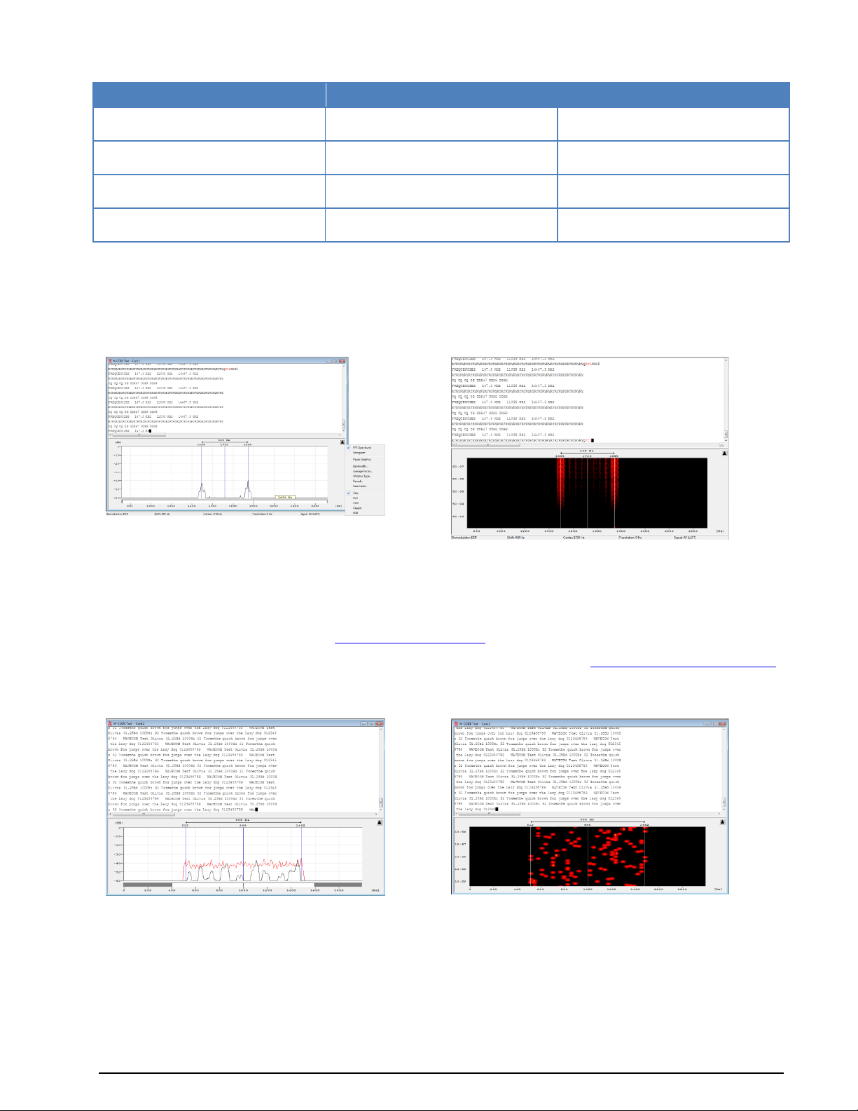
FFT Type
Start Frequency
End Freqeuncy
FFT HF
Offset Frequency
Bandwidth
FFT SUB
Offset Frequency
Bandwidth
FFT DIR
Offset Frequency – Bandwidth/2
Offset Frequency + Bandwidth/2
FFT SAT
Offset Frequency – Bandwidth/2
Offset Frequency + Bandwidth/2
FFT (HF, SUB, DIR and SAT)
Tuning FFT or Sonagram
In some modes a Tuning FFT or Sonagram is available. The FFT or Sonagram can be used to set the
center frequency, shift, and passband filter.
Tuning FSK Signals
Mark and Space are selected with the right and left cursor. The precision of the center frequency is very
important and directly influences the performance of the decoder.
After every change, the center frequency and shift are automatically updated.
Automatic tuning is also available. It works perfectly as long as there is only one input signal present in
the spectrum. To apply a filter, see “Passband Filter Support” on page 78.
Options can be set using the right mouse button or the context menu (see “FFT/Sonagram Context Menu”
on page 72). It is possible to remove the tuning FFT or Sonagram in the View Menu.
Tuning MFSK Signals
The highest and lowest tone of the signal is selected with the right and left cursor. The precision of the
center frequency is very important and directly influences the performance of the decoder.
After every change, the center frequency and shift are automatically updated.
Another tuning cursor group with 8 (green) cursors helps to measure the center, bandwidth and the distance between multiple carriers in a more convenient way. The 8 cursors can be moved freely. This feature is helpful when measuring signals with non-equal carrier distance (as CHINESE 4+4 signal).
WAVECOM Decoder W74PC, W-PCI/e, W-CODE, W-CLOUD Manual V9.1.0 Analysis Tools 81
Page 92

These options can be set using the right mouse button or the context menu (see “FFT/Sonagram Context
Menu” on page 72). It is possible to remove the tuning FFT or Sonagram in the View Menu.
Tuning PSK Signals
The upper and lower frequency boundaries of the signal is selected with the right and left cursor. With the
center cursor, the center frequency may be set more precisely. The precision of the center frequency is
very important and directly influences the performance of the decoder.
After every change, the center frequency is automatically updated and the bandwidth of the signal is set
according to the received mode.
Options can be set using the right mouse button or the context menu (see “FFT/Sonagram Context Menu”
on page 72). It is possible to remove the tuning FFT or Sonagram in the View Menu.
82 Analysis Tools WAVECOM Decoder W74PC, W-PCI/e, W-CODE, W-CLOUD Manual V9.1.0
Page 93

FFT and Sonagram
This analysis tool combines real-time FFT and sonagram analysis modes.
Detailed information for each of the analysis tools can be found in the corresponding descriptions, see
“FFT” on page 80 and “Sonagram” on page 84.
Options can be set using the right mouse button or the context menu (see “FFT/Sonagram Context Menu”
on page 72). It is possible to remove the tuning FFT or Sonagram in the View Menu.
Waterfall
The waterfall analysis produces a three dimensional display of FFT spectra over time, frequency and amplitude. The waterfall display aggregates many single measurements to 40 displayed spectra. An updated
measurement in the two-dimensional real-time FFT display only shows a fraction of the data, depending
on the modulation method. In contrast the FFT waterfall display also displays data in the time domain
A time histogram is displayed on the left-hand side of the display.
By clicking on the graph, the display will be paused and measurement cursors appear.
Options can be set using the right mouse button or the context menu (see “FFT/Sonagram Context Menu”
on page 72). It is possible to remove the tuning FFT or Sonagram in the View Menu.
WAVECOM Decoder W74PC, W-PCI/e, W-CODE, W-CLOUD Manual V9.1.0 Analysis Tools 83
Page 94

FFT Type
Start Frequency
End Freqeuncy
Waterfall HF
Offset Frequency
Bandwidth
Waterfall SUB
Offset Frequency
Bandwidth
Waterfall DIR
Offset Frequency – Bandwidth/2
Offset Frequency + Bandwidth/2
Waterfall SAT
Offset Frequency – Bandwidth/2
Offset Frequency + Bandwidth/2
Waterfall (HF, SUB, DIR and SAT)
Sonagram
A second widespread method for FFT display is the real-time sonagram, which displays the amplitude and
frequency values produced by the FFT over time. In the sonagram, the signal amplitude is displayed by
colour, with different colours representing different amplitudes. Sometimes this display is also called
“Spectrogram”.
This amplitude related spectrum analysis mode offers many hints to the distribution of a signal spectrum.
The operation is numerically identical to the real-time waterfall analysis, and is simply a different method
of visualisation.
Options can be set using the right mouse button or the context menu (see “FFT/Sonagram Context Menu”
on page 72). It is possible to remove the tuning FFT or Sonagram in the View Menu.
Making measurements
With the four cursors it is possible to make measurements in the frequency and time domain. To enable
the time cursors, click into the sonagram to freeze the screen. Then click with the right mouse button to
get the menu to set the time cursors.
T1 Add first cursor to the actual mouse position
T2 Add second cursor to the actual mouse position
Move Move T1 cursor and T2 cursor simultaneously
It is also possible to drag the cursor to a new location. If the cursor line gets in the upper our lower part of
the window, then the window will scroll automatically.
84 Analysis Tools WAVECOM Decoder W74PC, W-PCI/e, W-CODE, W-CLOUD Manual V9.1.0
Page 95

FFT Type
Start Frequency
End Freqeuncy
Sonagram HF
Offset Frequency
Bandwidth
Sonagram SUB
Offset Frequency
Bandwidth
Sonagram DIR
Offset Frequency – Bandwidth/2
Offset Frequency + Bandwidth/2
Sonagram SAT
Offset Frequency – Bandwidth/2
Offset Frequency + Bandwidth/2
The Trigger Mode option allows the real-time
oscilloscope to trigger on the Positive or the
Negative slope or to be switched Off.
The Trigger Level option allows conventional
level driven triggering to be set. The uncalibrated input voltage range is from +99%
to –99%.
Sonagram (HF, SUB, DIR and SAT)
Oscilloscope
In general, an oscilloscope is used to measure voltage over time. However, the oscilloscope displays a relative and un-calibrated value. After obtaining the measurement time, frequency can be determined.
By clicking on the graph, the display will be paused and measurement cursors appear for both axis.
Several Color schemes are available through the right-click menu.
WAVECOM Decoder W74PC, W-PCI/e, W-CODE, W-CLOUD Manual V9.1.0 Analysis Tools 85
Page 96
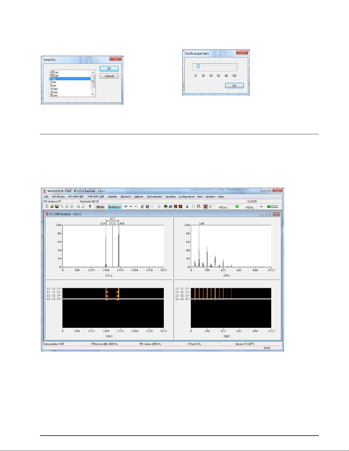
The vertical sensitivity may be set with the
option Time/Div. Nine predefined values are
available covering a range from 200 s to 100
ms per division.
Using the Oscilloscope Gain option, the horizontal un-calibrated input voltage sensitivity
may be adjusted from 0% to 100%.
FSK Analysis
The FSK analysis mode is an important tool to measure the baud rate and frequency shift of FSK transmissions. The magnitude of these property values may help to identify the transmission being monitored.
To open the FSK analysis window go to the HF-Modes menu and select Analysis/FSK Analysis, or use
the FSK Analysis button. The baud rate and spectrum window will open, but NOT the waterfall window.
After a few seconds the baud rate and spectrum window are updated.
The FSK analysis window consists of four panes:
A spectrum graph pane
A spectrum waterfall pane
A baudrate graph pane
A baudrate waterfall pane
Baudrate and Spectrum Window
The baudrate and spectrum window are two-dimensional displays of the monitored baud rate, measured in
Baud, and the spectrum of the transmission, measured in Hz, on a relative scale from 0 to 100. The dis-
86 Analysis Tools WAVECOM Decoder W74PC, W-PCI/e, W-CODE, W-CLOUD Manual V9.1.0
Page 97

plays are updated around every 5 seconds. The calculated baud rate, center frequency and frequency shift
values of the latest sample are stored to be used whenever a decoding mode is selected.
Two pairs of cursors may be placed in the baudrate and spectrum graph windows, to assist in manual
measurements. The values to which they point, and the difference between the two cursor values, are
shown above the cursors. When a pair of cursors is placed in one of these windows, graph display updating is halted, but signal sampling continues and is displayed in the waterfall window. The time cursor in
the waterfall window is placed on the selected sample.
Methods exclusively based on bit length measurement are unreliable for baud rate measurements. The
baud rate measuring process employed by the decoder is therefore based on a new method employing auto-correlation and subsequent Fast Fourier Transformation (FFT) presentation. Using this method, FSK
transmissions may be analyzed without problems. Be aware that when measuring the baud rate of codes
using code words which have a non-integer number of bits, e.g., asynchronous 7.5-bit ITA-2, the indicated baud rate will increase by a factor two.
Waterfall Window
To open the waterfall window, move the mouse to the left of the extreme right of the graph window. The
normal cursor will turn into a splitter - two parallel lines with arrows perpendicularly attached. Now, hold
and drag to place the boundary between the windows where you wish, when the mouse button is released.
The waterfall windows are two-dimensional displays of baud rate and spectrum versus time. The color intensity of the displays represents the energy density of the spectrum, and the value of the relative occurrence of a baud rate - for gray scale values, white is the highest intensity and black the lowest. A time
stamp points to the latest sample taken. The latest sample is color inverted to distinguish it from the previous samples.
If the user wishes to examine a particular sample, it may be selected in the waterfall window. The sample
is marked with the time cursor, cursors are placed in the graph window and updating is halted in that window.
FSK Analysis Options
To assist in the measurement of noisy signals, a peak measurement function and an averaging function
are available. When one of these options is selected the last five samples will be used for calculations. The
result is displayed in the graph window. The user may also select a larger time span as basis for calculations from anywhere in the waterfall window.
Measure Peak and Average Values
Select the function you wish to use from the Options menu. A checkmark is shown to the left of the option selected and five samples are inverted in the waterfall window selected to indicate the number of
samples used for the calculations.
If you wish to use a different number of samples in the calculation, place the mouse on the waterfall sample from which calculation should start, and hold and drag the mouse over as many samples as you want
to use.
The marked samples will be color inverted, cursors will appear in the graph window and the graph display
will show the average or peak value of the marked samples.
To disable peak or average measurement, uncheck it in the Options menu: the cursors will disappear, only one sample is marked in the waterfall window, and updating of the graph window will resume.
Examine Sample, Display Cursors
Click on the baudrate or the spectrum graph window to display the cursors, or click on the sample in the
waterfall window that you wish to examine. Graph window updates will stop and a pair of cursors will appear. You may move the cursors along the x-axis in normal Windows fashion. The matching waterfall
sample is marked with the time cursor.
Click on the graph window again to remove the cursors and resume graph window updates.
WAVECOM Decoder W74PC, W-PCI/e, W-CODE, W-CLOUD Manual V9.1.0 Analysis Tools 87
Page 98
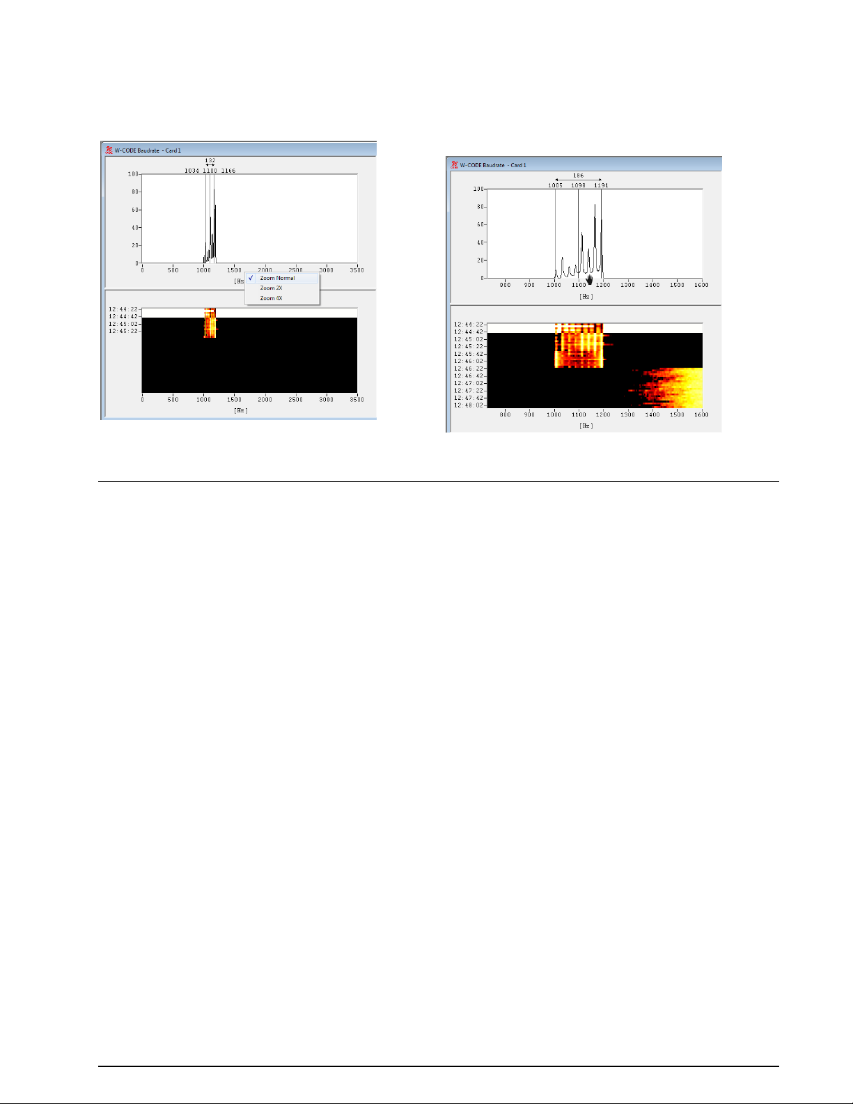
Right-click with the mouse into the spectrum
or baudrate graph pane (upper panes) and select if you like to Zoom 2X or or to Zoom 4X.
To adjust the frequency scale, move the cursor into the range of the frequency scale. If
you see the “Hand”, press the left mouse button and move the frequency slider.
Zoom
FSK Code Check
The purpose of the FSK Code Check is to automatically identify the mode of transmission, baud rate, frequency shift and center frequency.
FSK Code Check HF
FSK code check is started in automatic mode by selecting the Analysis | Code Check button or from HFModes | Analysis | FSK Code Check. This function has a high degree of accuracy when determining
baud rate, frequency shift and center frequency of HF FSK systems.
As an additional aid, FSK code check also offers an option to start the analysis manually after user entry of
baud rate, frequency shift and center frequency. To utilize this option the Auto button must be deselected. The software will then start data acquisition using the pre-selected parameters. If a pre-selected parameter has been changed data acquisition is atomatically restarted.
The selection of baud rate, frequency shift or center frequency is done by clicking on the status bar fields
or using the Demodulator menu.
If the FSK code check cannot identify a mode, the code check should be repeated. Data acquisition is continuously performed as a background task. Heavy fading or other disturbances during data acquisition
may prevent the identification of a mode.
You can also restart data acquisition by pressing the Resync button.
The 1.5 stop elements used in many Baudot transmissions will often prevent the correct determination of
the signal baud rate, or the baud rate will be calculated as twice its actual value. Distorted stop elements
may also lead to completely erroneous baud rate calculations. To prevent this malfunction, measurements
of Baudot transmissions take place using the standard speeds of 45.45, 50, 75, 100, 150 and 180 Baud, in
addition to the measured baud rate.
88 Analysis Tools WAVECOM Decoder W74PC, W-PCI/e, W-CODE, W-CLOUD Manual V9.1.0
Page 99
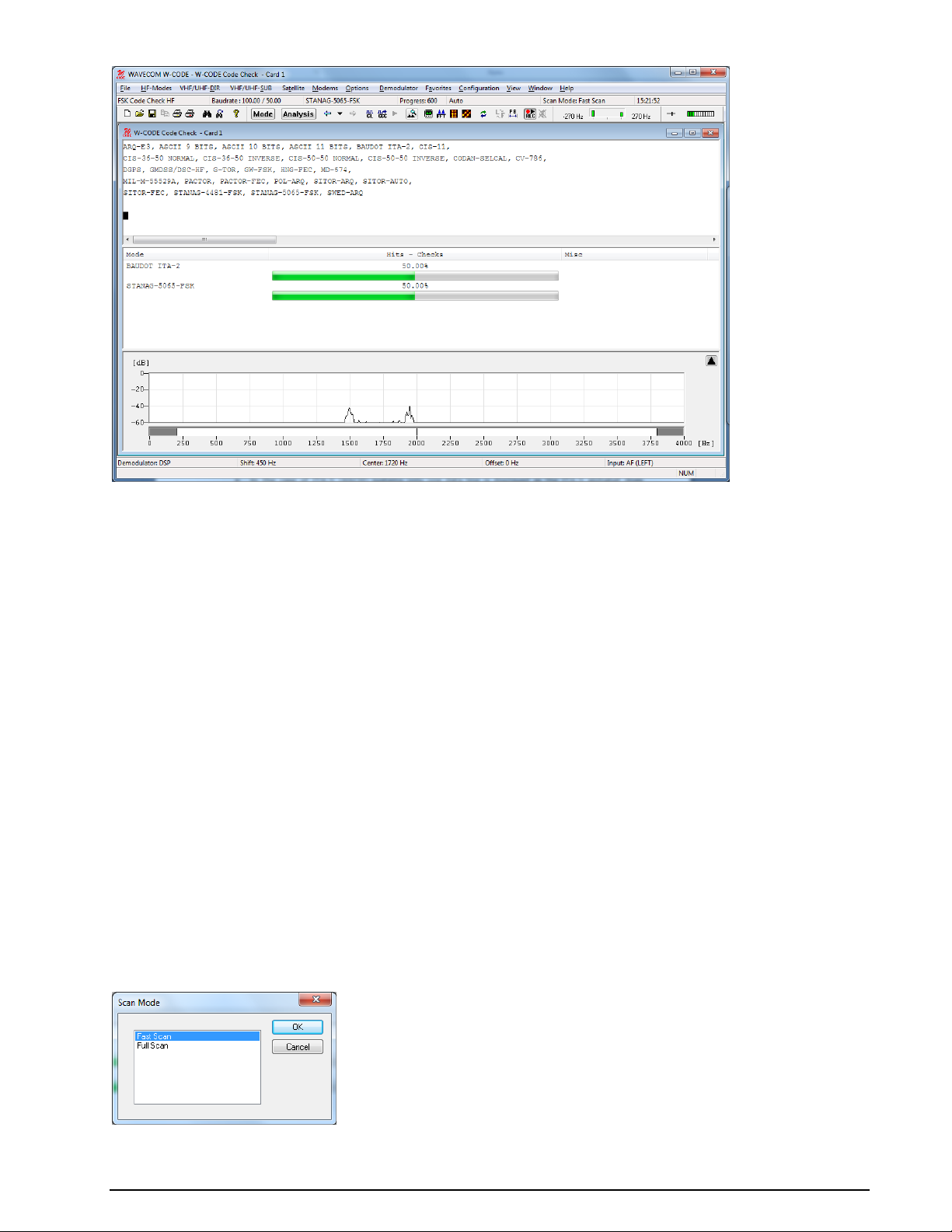
Steps:
After starting the FSK code check the frequency shift, center frequency and baud rate are deter-
mined. The values of these parameters are displayed in the appropriate fields after measurement
has finished.
The software then proceeds with code and system analysis. The incoming bit stream is tested
against known modes. For some modes using a high interleaving depth (e.g., RUM-FEC) large
quantities of input data are required. These modes therefore require longer to test and are tested
last.
The name of each identified system is displayed in the output window. An identified system may
be immediately started by double-clicking the system in the output window - for instance doubleclicking BAUDOT ITA-2 in the figure above will interrupt FSK code checking and immediately start
BAUDOT ITA-2.
The Hits-Checks will show you how often during checking a mode was successfully determined. If
multiple modes are listed this will indicate which mode should be tried.
Some modes are very difficult to distinguish, especially when the system is in idle mode. The de-
coded text including text representations of the special characters IDLE ALFA, IDLE BETA and RQ
are important additional classification aids in determining the mode under examination.
If a mode is uniquely identified, the software will switch to the identified mode and decoding is ini-
tiated with the measured values of mode, baud rate, shift, and center frequency.
If two or more different systems are identified or if too many transmission errors occur, an auto-
matic switch to a mode will not take place.
Fast Scan/Full Scan
The Scan Mode can be selected by Options | Scan Mode… or by double-clicking the Scan Mode field in
the Status Bar.
WAVECOM Decoder W74PC, W-PCI/e, W-CODE, W-CLOUD Manual V9.1.0 Analysis Tools 89
Page 100
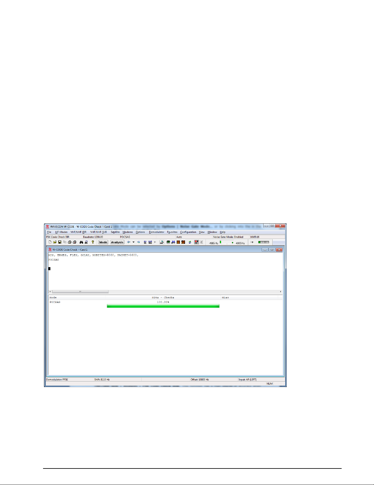
The software proceeds to create a list of modes to check, which is displayed in the Code Check window.
The content of this list depends on the selection of the Fast Scan or Full Scan options.
In Fast Scan mode, the list only contains the modes which are known to use the measured baud
rate, to reduce the evaluation time.
In Full Scan every mode which is suitable for an FSK code check is listed, and all possible combi-
nations are checked.
FSK Code Check DIR
FSK code check is started in automatic mode by selecting the Analysis | Code Check button or from
VHF/UHF-DIR | Analysis | FSK Code Check. This function has a high degree of accuracy when determining baud rate, frequency shift and center frequency of HF FSK systems.
As an additional help FSK code check also offers an option to start the analysis manually after user entry
of baud rate, frequency shift and center frequency. To utilize this option the Auto button must be deselected. The software will then start data acquisition using the pre-selected parameters. If a pre-selected
parameter has been changed data acquisition is atomatically restarted.
The selection of baud rate, frequency shift or center frequency is done by clicking on the status bar fields
or using the Demodulator menu.
If the FSK code check cannot identify a mode, the code check should be repeated. Data acquisition is continuously performed as a background task. Heavy fading or other disturbances during data acquisition
may prevent the identification of a mode.
You can also restart data acquisition by pressing the Resync button.
Because this kind of signal is not continuous, there is a need for a Noise Gate. The status of the noise
gate is displayed in the status bar; it examines the input signal and tries to determine if a valid signal is
available which can be processed, or if the input consists only of noise.
Steps:
After starting the FSK code check the frequency shift, center frequency and the baud rate are de-
termined. The values of these parameters are displayed in the appropriate fields after the measurement has completed.
The software then proceeds with code and system analysis. The incoming bit stream is tested and
compared against known modes.
90 Analysis Tools WAVECOM Decoder W74PC, W-PCI/e, W-CODE, W-CLOUD Manual V9.1.0
 Loading...