

Page 1

BitView Manual V2.5.00
WAVECOM W-BV
by WAVECOM ELEKTRONIK AG
Page 2

PUBLISHED BY
WAVECOM ELEKTRONIK AG
Hammerstrasse 8
CH-8180 Buelach
Switzerland
Phone: +41-44-872 70 60
Fax: +41-44-872 70 66
Email: info@wavecom.ch
Internet: http://www.wavecom.ch
© by WAVECOM ELEKTRONIK AG. All rights reserved.
Reproduction in whole or in part in any form is prohibited without written consent of the copyright owner.
The publication of information in this document does not imply freedom from patent or other protective rights of
WAVECOM ELEKTRONIK AG or others.
All brand names in this document are trademarks or registered trademarks of their owners.
Specifications are subject to change without further notice.
Printed: Mai 29, 2012
Page 3

Contents
Introduction 1
Introduction .................................................................................................... 1
Training ........................................................................................................ 1
Source Code .................................................................................................... 1
Company Profile ............................................................................................... 1
Revisions ....................................................................................................... 2
Requirements................................................................................................... 3
Limitations ..................................................................................................... 3
Installation 3
W-BV Software Installation ................................................................................... 3
W-BV Hardware Installation ................................................................................ 10
W-BV Licensing ............................................................................................. 10
CodeMeter .NET API installation ................................................................. 4
CodeMeter Runtime installation ................................................................... 5
MatLab Runtime installation ....................................................................... 6
BitView installation ................................................................................ 8
BitView defaults installation ....................................................................... 9
Paths ................................................................................................. 9
CmStick ........................................................................................... 10
W-BV Software Options ......................................................................... 10
W-BV license checking .......................................................................... 11
Getting Started 11
Program Start ................................................................................................ 11
Menu 13
Bit Stream Processing ....................................................................................... 13
Analysis Sets ................................................................................................. 14
Reports ....................................................................................................... 15
Properties Window .......................................................................................... 16
History Explorer Window ................................................................................... 17
Toolbox Window ............................................................................................ 18
Preferences ................................................................................................... 18
Layout Settings .............................................................................................. 19
Function Library 23
Common Functions .......................................................................................... 23
Auto-Calculation .................................................................................. 23
Enable or Disable Functions ..................................................................... 25
Progress Calculator ............................................................................... 25
Source/Sink .................................................................................................. 25
Import Text Data .................................................................................. 25
Import Hex Data .................................................................................. 26
Import Binary Data ............................................................................... 26
Import IAS Bitstream ............................................................................. 26
Export Text Data .................................................................................. 27
Generate Pseudo-Noise ........................................................................... 27
Synchronization .............................................................................................. 28
Preamble .......................................................................................... 28
BitView Manual V2.5.00 WAVECOM W-BV Contents iii
Page 4

Binary Modulation ........................................................................................... 29
NRZ-I ............................................................................................. 29
NRZ-M ............................................................................................ 29
NRZ-S ............................................................................................. 29
Bi-Phase-L (Manchester) ......................................................................... 30
Bi-Phase-M ....................................................................................... 30
Bi-Phase-S ........................................................................................ 30
DBi-Phase-M ..................................................................................... 31
DBi-Phase-S ...................................................................................... 31
Bit Manipulation ............................................................................................. 32
De-Stuffing (HDLC) ............................................................................. 32
Mirroring .......................................................................................... 32
Rotation ........................................................................................... 32
Shift ............................................................................................... 33
Polarity ............................................................................................ 33
De-Interleaving Block ............................................................................ 33
De-Interleaving Stream ........................................................................... 34
AND / OR / XOR / NOT ......................................................................... 35
AND / OR / XOR / NOT Range ................................................................. 35
Extraction (Mask) ................................................................................. 36
Extraction (Range) ................................................................................ 36
Cutting............................................................................................. 36
Decoding/Equalizer .......................................................................................... 37
Viterbi-Decoding ................................................................................. 37
De-Puncturing .................................................................................... 37
Standard Depuncturing ........................................................................... 38
Difference-Decoding ............................................................................. 38
BCH-Decoding ................................................................................... 39
Block Code Analysis ............................................................................. 40
Convolutional Code Analysis .................................................................... 40
General Reed Solomon Decoding ............................................................... 41
CRC & Polynomial .......................................................................................... 42
CRC (1..32) ....................................................................................... 42
CRC-8 ............................................................................................. 43
CRC-10 ............................................................................................ 43
CRC-12 ............................................................................................ 44
CRC-16 ............................................................................................ 44
CRC-CCITT ...................................................................................... 45
CRC-32 ............................................................................................ 45
Parity (Even/Odd/Mark/Space) .................................................................. 46
Parity from H-Matrix ............................................................................. 46
Parity from polynomial ........................................................................... 47
Unpacking/Decompress ..................................................................................... 48
Unzip .............................................................................................. 48
Descrambling ................................................................................................ 48
Descrambler (PN) ................................................................................. 48
Channel Encoding ........................................................................................... 49
Convolutional Encoding .......................................................................... 49
Channel Decoding (Protocol) ............................................................................... 50
ARQ-E ............................................................................................ 50
SITOR ............................................................................................. 50
FEC-A ............................................................................................. 50
BAUER ........................................................................................... 50
HNG-FEC ......................................................................................... 50
RUM-FEC......................................................................................... 50
ITA-3 (M.342) .................................................................................... 51
ITA-5 .............................................................................................. 51
PSK-31 (Varicode) ............................................................................... 51
Source Decoding (Alphabet) ................................................................................ 51
Latin ............................................................................................... 51
Third-shift Greek ................................................................................. 51
Cyrillic ............................................................................................ 51
Tass-Cyrillic ...................................................................................... 52
Third-shift Cyrillic ................................................................................ 52
iv Contents BitView Manual V2.5.00 WAVECOM W-BV
Page 5

Hebrew ............................................................................................ 52
Arabic Baghdad-70 ............................................................................... 52
Arabic Baghdad-80 (ATU-80) ................................................................... 52
Bulgarian .......................................................................................... 52
Swedish ........................................................................................... 53
Danish-Norwegian ................................................................................ 53
German ............................................................................................ 53
French ............................................................................................. 53
US ................................................................................................. 53
ASCII .............................................................................................. 53
UNICODE ........................................................................................ 54
UTF-7 ............................................................................................. 54
UTF-8 ............................................................................................. 54
Code Page Decoding ............................................................................. 54
Pager Numeric .................................................................................... 54
Analysis Tools ............................................................................................... 55
Symbol Statistics ................................................................................. 55
Autocorrelation ................................................................................... 55
Signal Duration ................................................................................... 56
Bit Sync Analysis ................................................................................. 57
Analysis Set Library 59
Familiarize yourself with Bit Analysis ..................................................................... 59
Custom Library 59
Custom Functions ............................................................................................ 59
Symbol Transcoding .............................................................................. 60
STANAG-4285 Deinterleaver ................................................................... 60
STANAG-4285 Descrambler .................................................................... 61
Stream setup for Viterbi .......................................................................... 61
Simulate STANAG-4285......................................................................... 62
Want to Roll Your Own functions? ......................................................................... 62
Adding a Custom Function .................................................................................. 64
Constraints ................................................................................................... 64
Important Notes .............................................................................................. 65
Steps to Write a Custom Function in C# .NET ............................................................. 65
Steps to Write a Custom Function with MatLab ........................................................... 65
Source Code Template / Example (C# .NET) .............................................................. 66
CustomLibFunction.cs ....................................................................................... 66
Source Code Template / Example (C# .NET for MatLab) ................................................ 69
BVCustLibMatlab.cs ............................................................................. 69
Source Code Template / Example (MatLab) ............................................................... 76
MatlabFunction.m ........................................................................................... 76
Appendix 77
License Terms................................................................................................ 77
Address ....................................................................................................... 78
CodeMeter and CmStick .................................................................................... 79
CodeMeter Control Center ....................................................................... 79
CodeMeter WebAdmin ........................................................................... 82
Glossary of Terms 93
Index 95
BitView Manual V2.5.00 WAVECOM W-BV Contents v
Page 6

Page 7

Introduction
Introduction
WAVECOM-BitView (W-BV) enables the user to analyze any bit stream. The range of functions extends
from the display of a bit stream in various formats, simple bit stream manipulations, over statistical
functions to complex mathematical functions and functions based on coding theory. The tools are targeted
at users with experience in bit stream analysis. To understand some of the functions a comprehensive
mathematical knowledge is a prerequisite.
Direct bit stream input from W51PC, W61PC, W-PCI, W-PCIe and W-CODE is supported.
BitViewTool supports the Windows 2000, XP, Server 2008 and Windows 7 32-bit and 64-bit operating
systems.
The product that you bought incorporates the latest technology in data decoding together with the latest
software release available at the time of shipment.
Please, check our website http://www.wavecom.ch for software updates.
Always check the latest documentation on the installation CD or on our website.
We thank you for choosing a WAVECOM decoder and look forward working with you in the future.
This chapter introduces WAVECOM, the field of activity of the company, and how you may benefit from the
expertise of WAVECOM.
Throughout this document the terms “BitView”, “W-BV” and “BitViewTool” all designate “WAVECOMBitView”.
Training
WAVECOM offers all our customers a complete, professional training program covering all the key features
of our products.
Depending on your skills (if you are an expert or a beginner), together we will work out a special training
program for you.
Training is available on your location or in Switzerland.
Source Code
Source code is available for government bodies. Please, inquire an offer from WAVECOM, if you plan to
add your own modes.
Company Profile
WAVECOM ELEKTRONIK GmbH was founded in 1985 in Hohentengen, Germany, close to the Swiss border.
In 1991 the company moved to Switzerland and established itself as WAVECOM ELEKTRONIK AG. Now
located in Buelach it is within close vicinity of Zurich airport.
The company has focused on decoding and analysis systems for wireless data transmissions. The wide
product range spans from professional, high performance systems to devices for private and amateur
radio use.
The very high quality standards combined with high system performance are appreciated by all customers
worldwide. A global network of authorized sales partners ensures that local assistance and basic level
support can be provided in most places. More than 95% of all units sold are exported. The majority of the
customers are government agencies, defense organizations and the telecommunication industry.
BitView Manual V2.5.00 WAVECOM W-BV Introduction 1
Page 8

Version
Date
Changes
1.1
10-May-2007
2.0
05-Nov-2007
Installation folders changed
‘Hide on close’ preference added
Layout settings removed from context menu
Layout settings now in the property grid
Graphic layout added
‘Inversion’ function name inversion changed to ‘polarity’
Bit Sync Analysis added
Custom library updated
2.1
14-Mar-2008
Hexadecimal view added
Enhanced printer dialog
MatLab custom libraries
2.1.01
15-Apr-2008
General overwork:
Improved readability
Extended explanations
‘Parameters’ window changed to ‘Properties’ window
2.2.00
22-Jul-2008
Works with W51PC, W61PC and W-CODE
New functions:
Unzip
Autocalculation
Enable function
2.3.00
7-Feb-2009
New functions:
AND/OR/XOR/NOT Range
Extraction (Range)
General Reed-Solomon Decoding
Parity (Even/Odd/Mark/Space)
Parity from H-Matrix
Parity form polynomial
Descrambler (Pseudo Noise)
Pager Numeric
Custom libraries with source code
Additional information in the status line of the main window
Enhanced performance of the Auto-Calculation function
Functions may be enabled or disabled in History Explorer
2.4.00
16-Mar-2011
MatLab Upgrade to Runtime 7.11 (R2009b)
MatLab dotnetbuilders with option "Embed CTF archive into the Appli-
cation". As a result, the administrator rights for BitView are no longer
required
Context sensitive help
ImportIasBitStream with two parameter sets for W-CODE and W61PC
Bit-Buffer increased from 500’000 bits to 1’000’000 bits
Autocalculation for enabled disabled function corrected
WiBu CodeMeter Runtime updated to version 4.20c 10, CodeMeter
.Net Api 4.20
2.4.1
9-Mai-2011
Matlab dll replaced
About 40% of the turnover is invested in research and development. The employees at WAVECOM
ELEKTRONIK AG are mainly engineers with experience in DSP technology, computer and RF hardware
development, and software engineering and radio data transmission. Access to external know-how and
human resources enlarges the capabilities for realizing projects. Manufacturing is outsourced to specialized
companies within Switzerland which can handle today's needs for processing surface mount components
and fine-pitch structures.
WAVECOM ELEKTRONIK AG does not have any juridical or financial links or connections to other
companies or official bodies and is completely owned by Mr. Christian Kesselring.
Revisions
2 Introduction BitView Manual V2.5.00 WAVECOM W-BV
Page 9
2.5.0
1-May-2012
Add HF STANAG-4285 into “Configuration W-CODE Decoder
Bitstream Type”
Add “Convolutional Encoder”, “Generate Pseudo-Noise” functions
Add various functionalities to analyse STANAG4285 bitstream
Requirements
.NET Framework version 2.0 must be installed. The framework is included in the setup and is installed if
missing on the system.
Limitations
In this version of BitView, the maximum number of bits that can be imported is limited to one million bits.
Bear in mind that some formatting functions such as bit highlighting consume a lot of CPU power and may
require considerable time to complete, especially on less powerful systems. Reducing the number of
imported bits will speed up the application.
Bit streams are imported completely raw and unsynchronized, i.e., BitView will not recognize additional
information like confidence levels from soft-decision decoders or symbol boundaries for m-ary modulation
types. Any such information must be removed using the BitView toolbox functions.
Installation
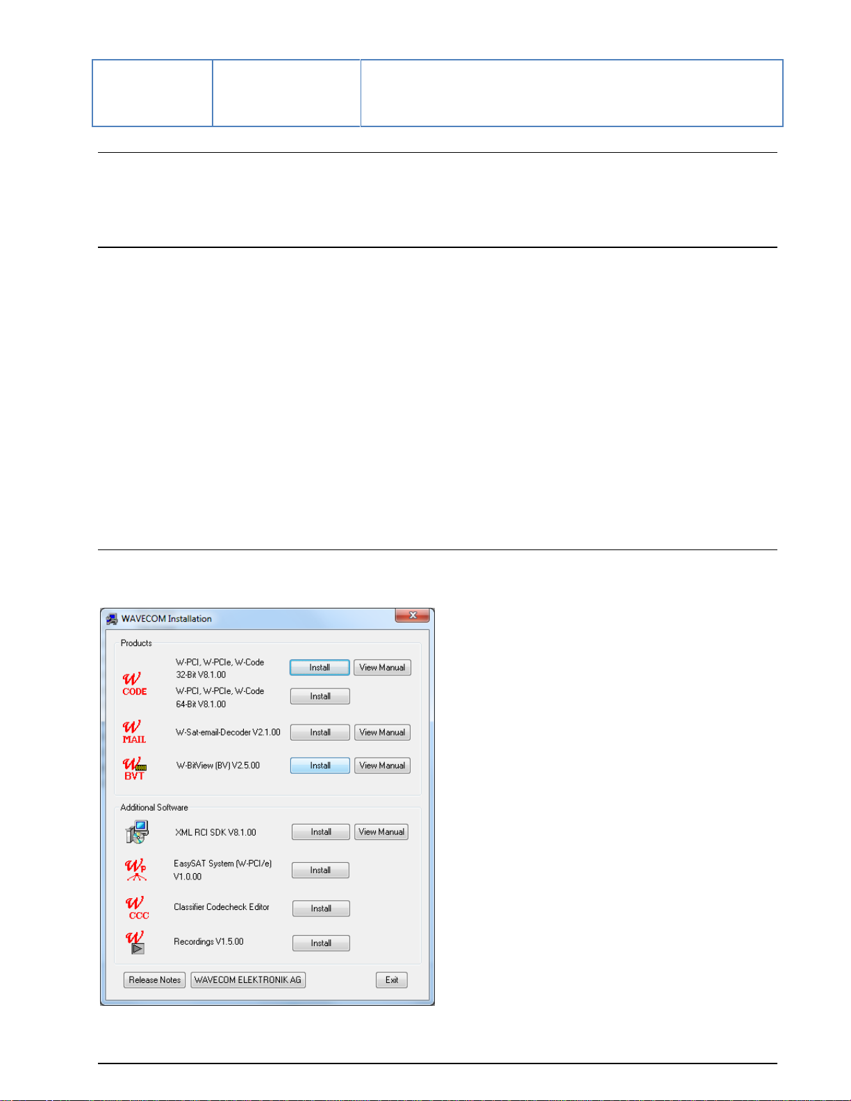
W-BV Software Installation
To install the application, you can use the Wavecom installation DVD, click the corresponding button.
BitView Manual V2.5.00 WAVECOM W-BV Installation 3
Page 10
You can also run SetupBitViewTool.exe directly. Files are then unpacked and copied to the installation
folder. Ini files are not generated.
By default BitViewTool will be installed in the WAVECOM folder, where other WAVECOM products may be
installed.
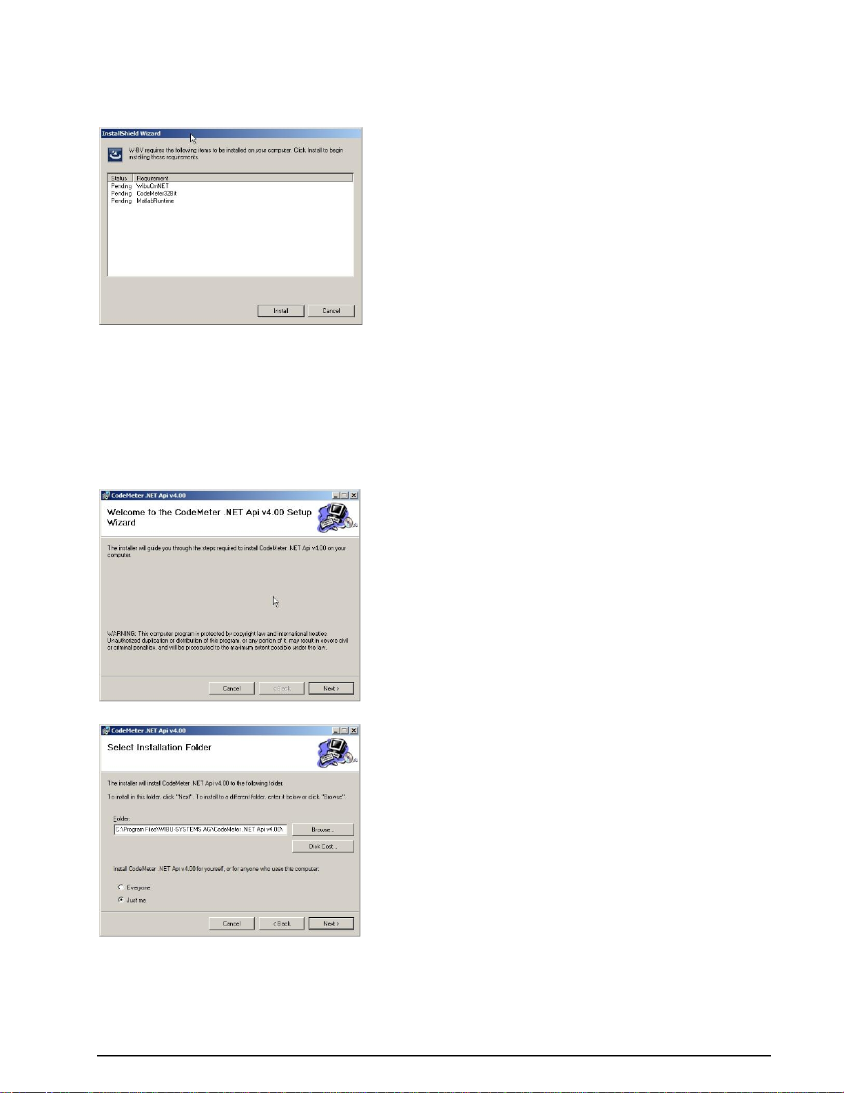
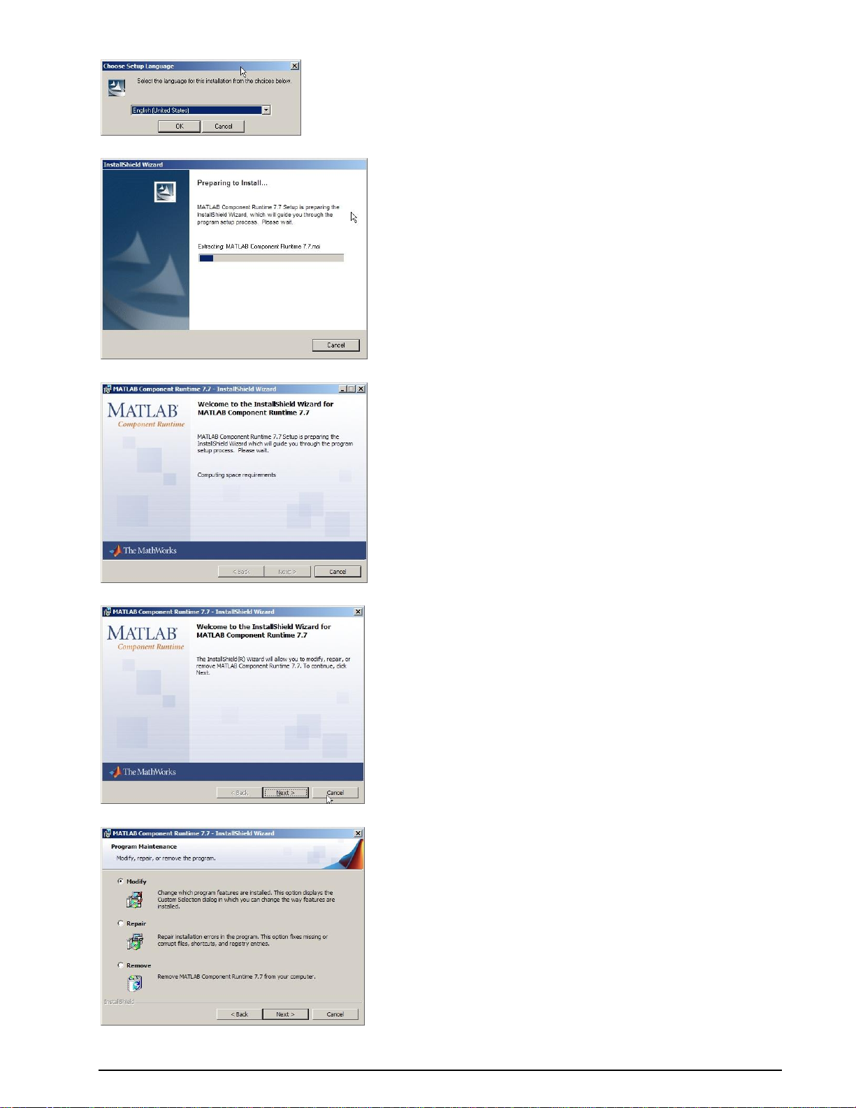
Press Install to continue the installation of the four components which constitute BitView,
CodeMeter .NET API
CodeMeter Runtime
MatLab Runtime
BitView application
The installation is self-explanatory and to complete it follow the instruction on the screen.
CodeMeter .NET API installation
Pressing Next will start the installation of this component.
4 Installation BitView Manual V2.5.00 WAVECOM W-BV
Page 11
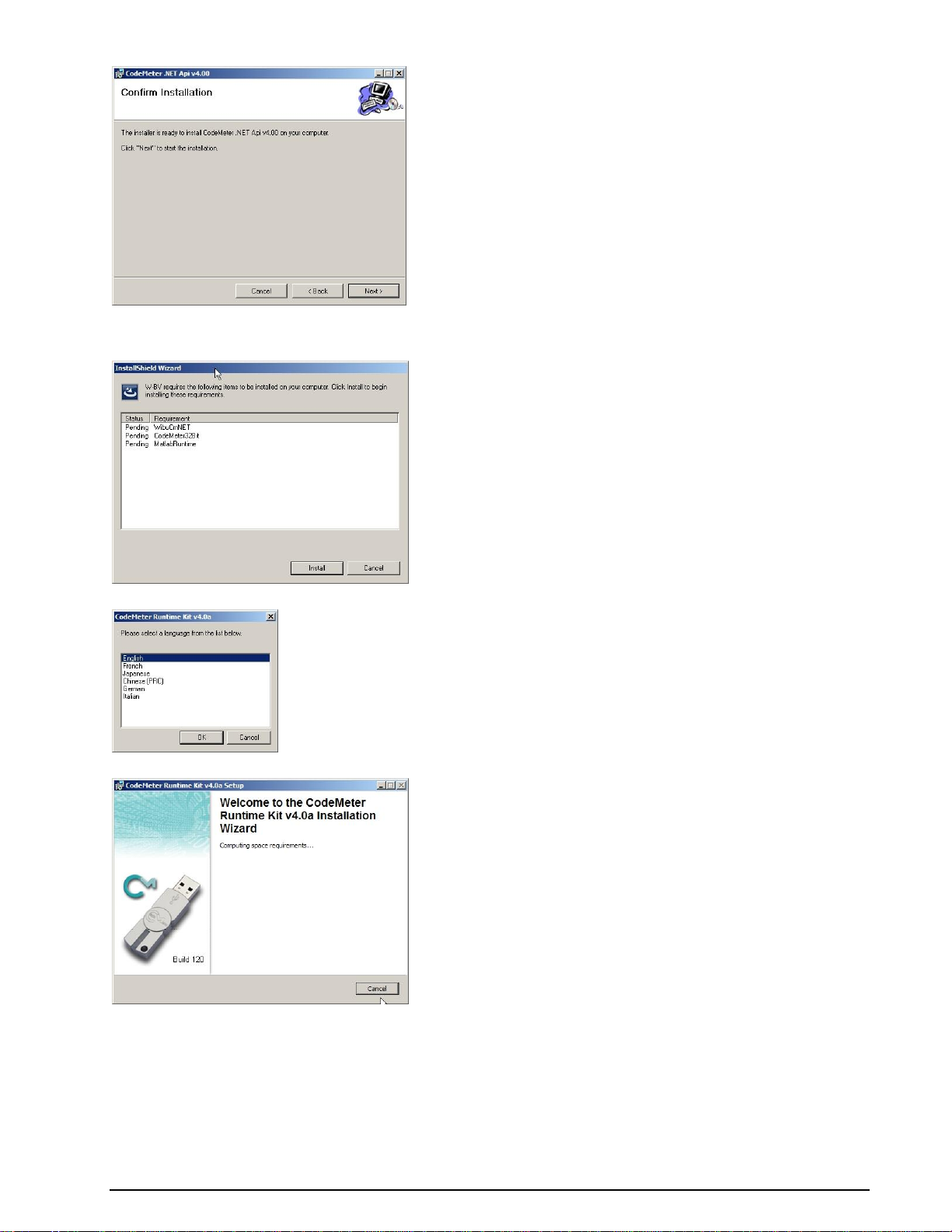
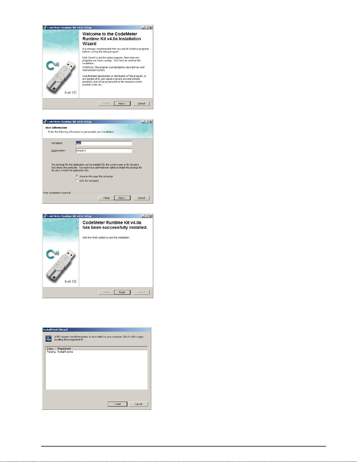
CodeMeter Runtime installation
BitView Manual V2.5.00 WAVECOM W-BV Installation 5
Page 12
MatLab Runtime installation
6 Installation BitView Manual V2.5.00 WAVECOM W-BV
Page 13
BitView Manual V2.5.00 WAVECOM W-BV Installation 7
Page 14
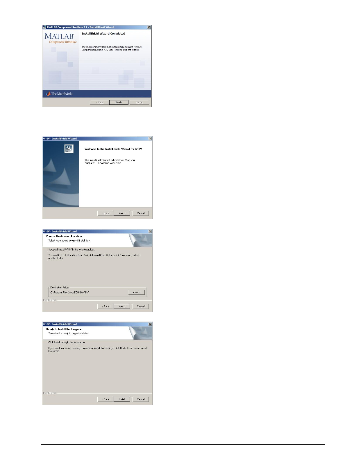
BitView installation
8 Installation BitView Manual V2.5.00 WAVECOM W-BV
Page 15
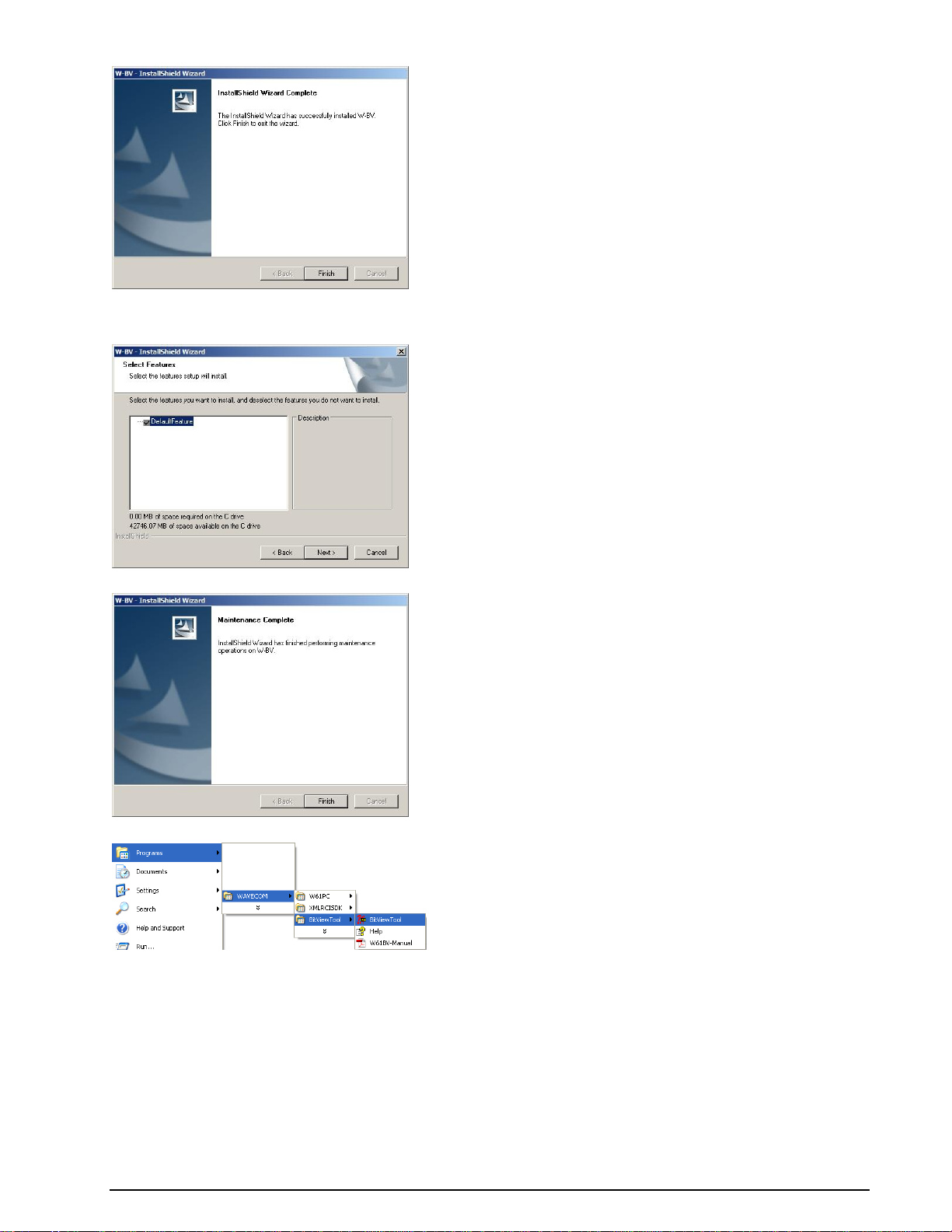
BitView defaults installation
Press Finish to complete the installation of all BitView components.
BitViewTool may be uninstalled by using the Add/Remove Programs item found in the Control Panel
menu.
Paths
Examples and CustomLib files are copied to the following folder:
Windows XP and earlier:
Documents and Settings\All Users\Documents \WAVECOM\BitViewTool\
Documents and Settings\All Users\Shared Documents \WAVECOM\BitViewTool\
Windows 7:
BitView Manual V2.5.00 WAVECOM W-BV Installation 9
Page 16

Users\Public\Public Documents\WAVECOM\BitViewTool\
W-BV Hardware Installation
Apart from a Windows PC and software protection hardware, no additional hardware is required to operate
the software.
CmStick
Software protection hardware has to be connected to the computer. The hardware device used for the
software protection is called the CmStick and is available as:
A small USB device
A PC Card (CmCard/M, Cardbus, 32 Bit)
An Express Card|34 (CmCard/E)
The W-BV application will not start if the appropriate and valid licenses are not found on a CmStick
connected to the system.
After the installation of the software on the computer, the CmStick icon will be displayed in the tray
icon area.
Note: when a CmStick is plugged into an USB socket of a LCD monitor, the CmStick will no longer be
detected by the software protection server if the monitor is switched off. Hence a running application
relying on the licenses stored on such a CmStick will stop working or disable its features.
W-BV Licensing
On request, we can generate different license models, even complex ones
Single user license
Evaluation licenses (number of starts, limited usage period, activation and/or expiration time)
Modular licenses (activation of additional functions)
Also licenses from other software manufacturers can be stored on a CmStick containing WAVECOM
licenses
W-BV Software Options
Additional functions or services may be licensed to work with your tool, e.g.:
W-PCIe and W-PCI decoders
W-CODE decoder
W61PC decoder
To process an order, the following information is required:
full address
ordered items
email or post delivery
10 Installation BitView Manual V2.5.00 WAVECOM W-BV
Page 17
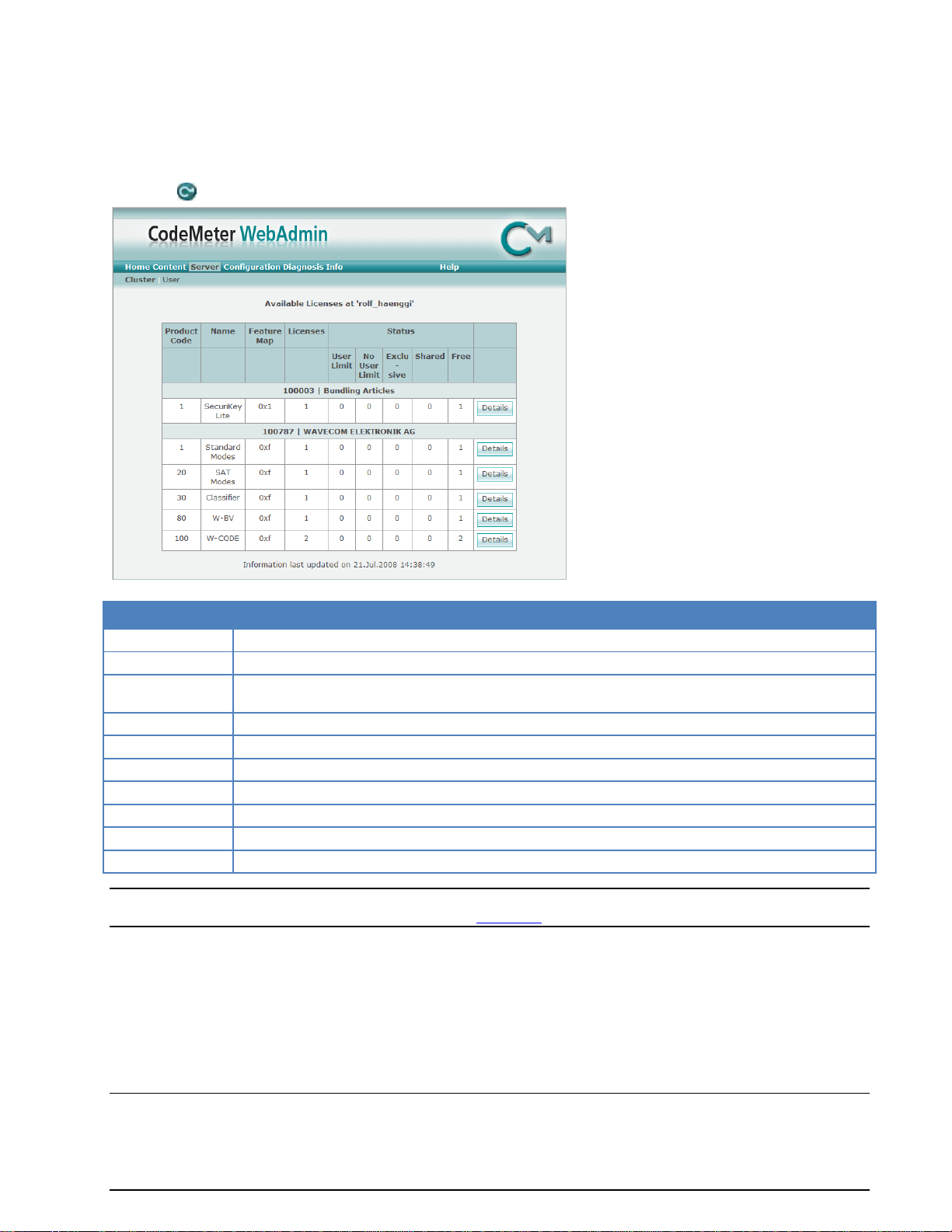
Item
Remarks
Product Code
Displays the Product Code
Name
Displays the name of the Product Item, normally the name of the product
Feature Map
Displays the Feature Map. WAVECOM uses the Feature Map to control the software upgrade period
Licenses
Displays the total number of network licenses
User Limit
Displays the number of licenses, which are currently used in the User Limit mode
No User Limit
Displays the number of licenses that are currently used in the No User Limit mode
Exclusive
Displays the number of licenses that are currently used in the Exclusive mode
Shared
Displays the number of licenses that are currently used in the Shared mode
Free
Displays the number of licenses that are currently free
Details
Displays detailed information about the respective network licenses in use
serial number of CmStick
remote context file of CmStick to be updated, if applicable
W-BV license checking
To check the license(s) on the CmStick follow these steps:
Click the icon in the tray icon area.
Important: If you have multiple CmSticks plugged into computers in a local network, then read the
CodeMeter and CmStick chapter included in the “Appendix” on page 77.
Getting Started
Program Start
Starting the program will introduce a license check procedure.
BitView Manual V2.5.00 WAVECOM W-BV Getting Started 11
Page 18
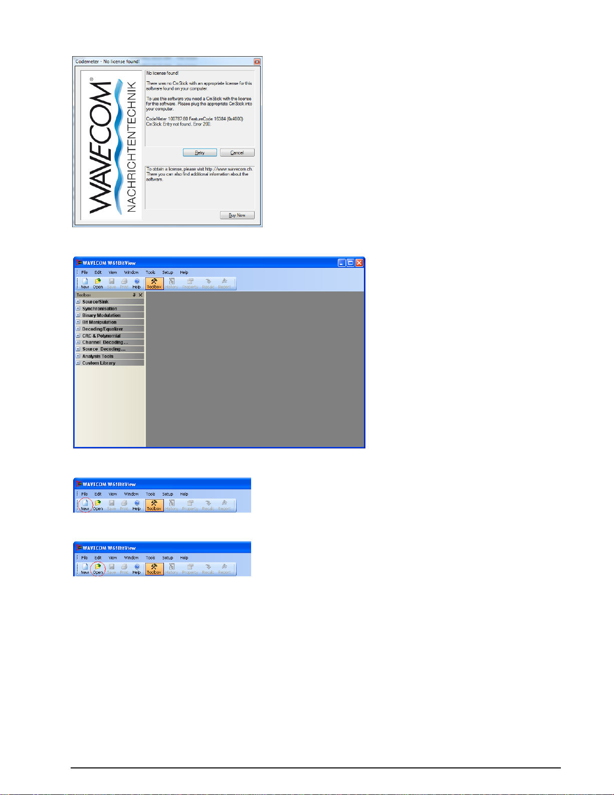
If a valid license key was not found, the following message appears on the screen.
If a valid license key was found the application is started. The Toolbox, which contains the function
library, is displayed and enables the user to import a bit stream from a selection of different sources.
Alternatively, using the New button from the Toolbar, an empty document window is opened which
allows the user to manually create a bit stream, or copy and paste a bit stream from another source.
Another option, using the Open button from the Toolbar, allows a previously saved Analysis Set (stored
in an .XML file) to be opened (see later in this manual for details).
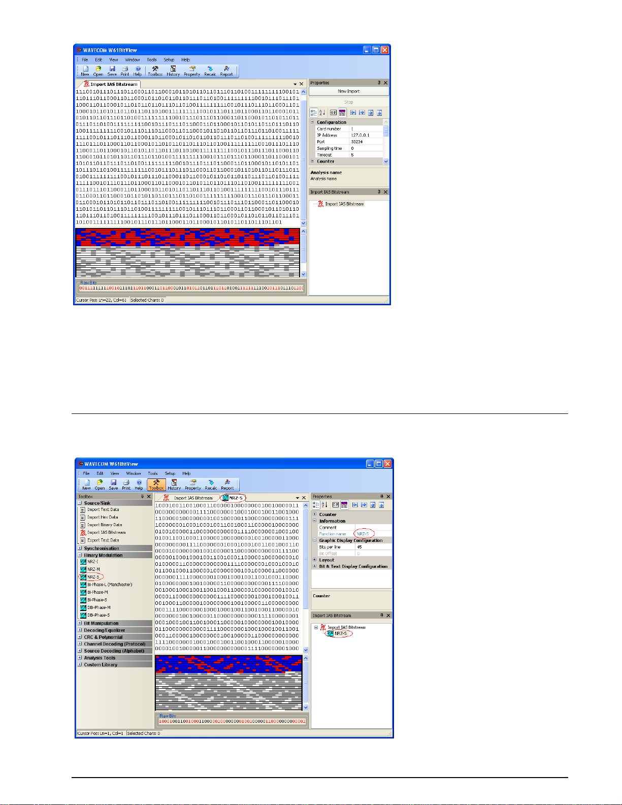
Bit Stream Import
An imported bit stream is shown in a document window, and the Properties and History Explorer
windows are opened. In general, the Properties window displays all the properties of a selected function,
and the History Explorer window shows the dependencies of all functions in a tree view.
12 Getting Started BitView Manual V2.5.00 WAVECOM W-BV
Page 19
Menu
Bit Stream Processing
An imported bit stream may be processed using any of the functions found in the library.
BitView Manual V2.5.00 WAVECOM W-BV Menu 13
Page 20
The position of the cursor (line, column and index) in the bit display is continuously indicated in the
bottom line of the application window. To select a number of bits, press and hold the left mouse button.
The selected bits are marked in blue and the number of selected bits, and the decimal values of these bits
interpreted as big-endian or little-endian values are displayed in the bottom line. Left-clicking anywhere in
the display window will cancel the selection.
The processed bit stream is shown in a new document window. All document windows are shown as
tabbed windows.
Analysis Sets
Functions and data may be combined to form a so-called Analysis Set, which contains an imported bit
stream and the configured functions applied to the bit stream. The user may define and create different
analysis paths, as may be seen in the History Explorer. The imported bit stream is processed according
to the configuration settings of the selected functions.
Using the Save button in the toolbar, Analysis Sets may be saved in an XML file. Using the Open button,
an Analysis Set may be reloaded at any time.
14 Menu BitView Manual V2.5.00 WAVECOM W-BV
Page 21
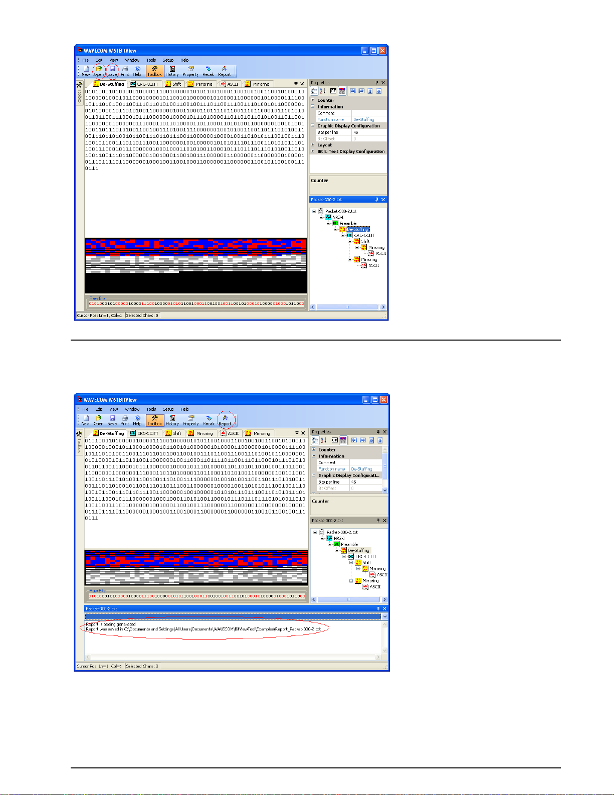
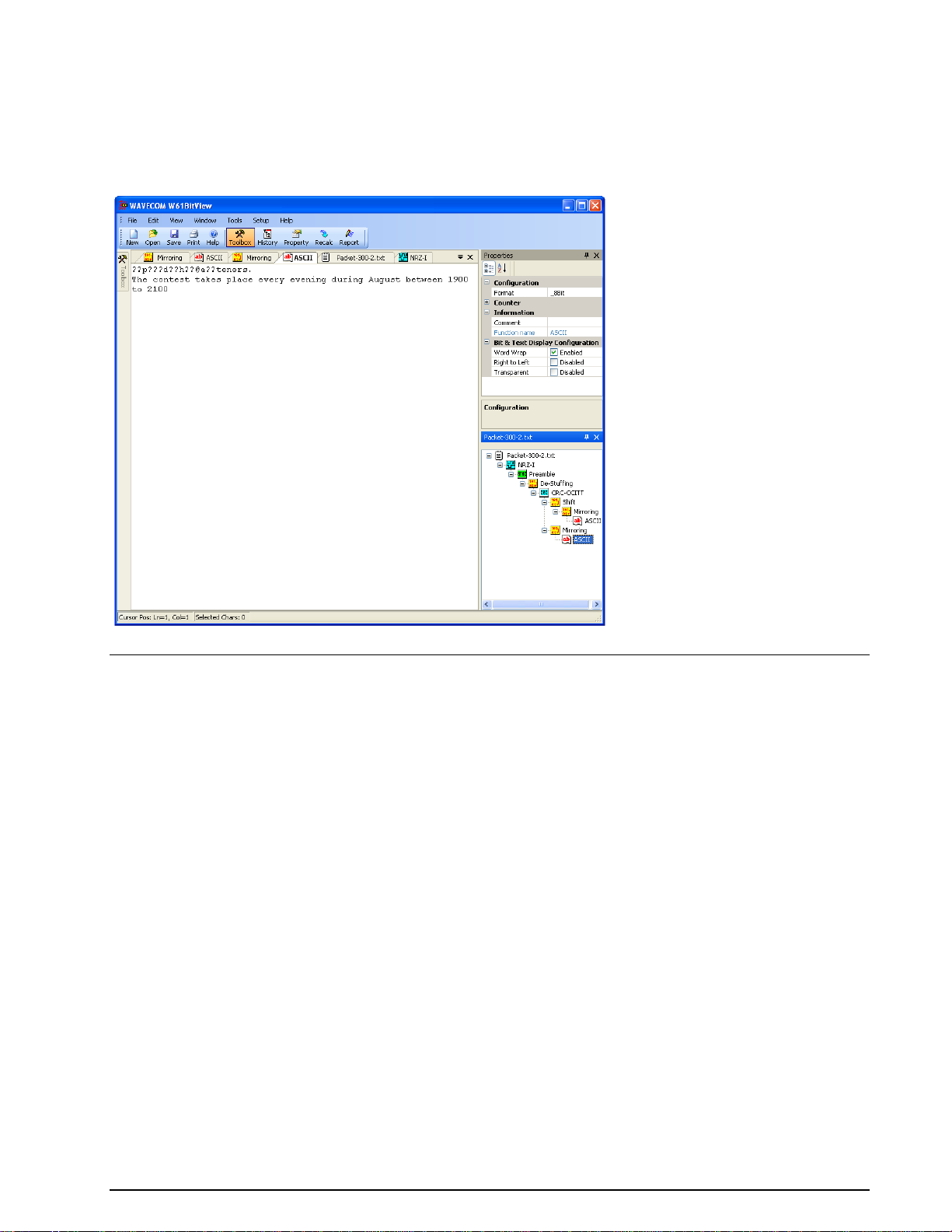
Reports
Using the Report button a complete Analysis Set may be generated and saved as a text file or a XML
file.
Example of a report stored in a text file.
BitView Manual V2.5.00 WAVECOM W-BV Menu 15
Page 22

Example of a report stored in a XML file.
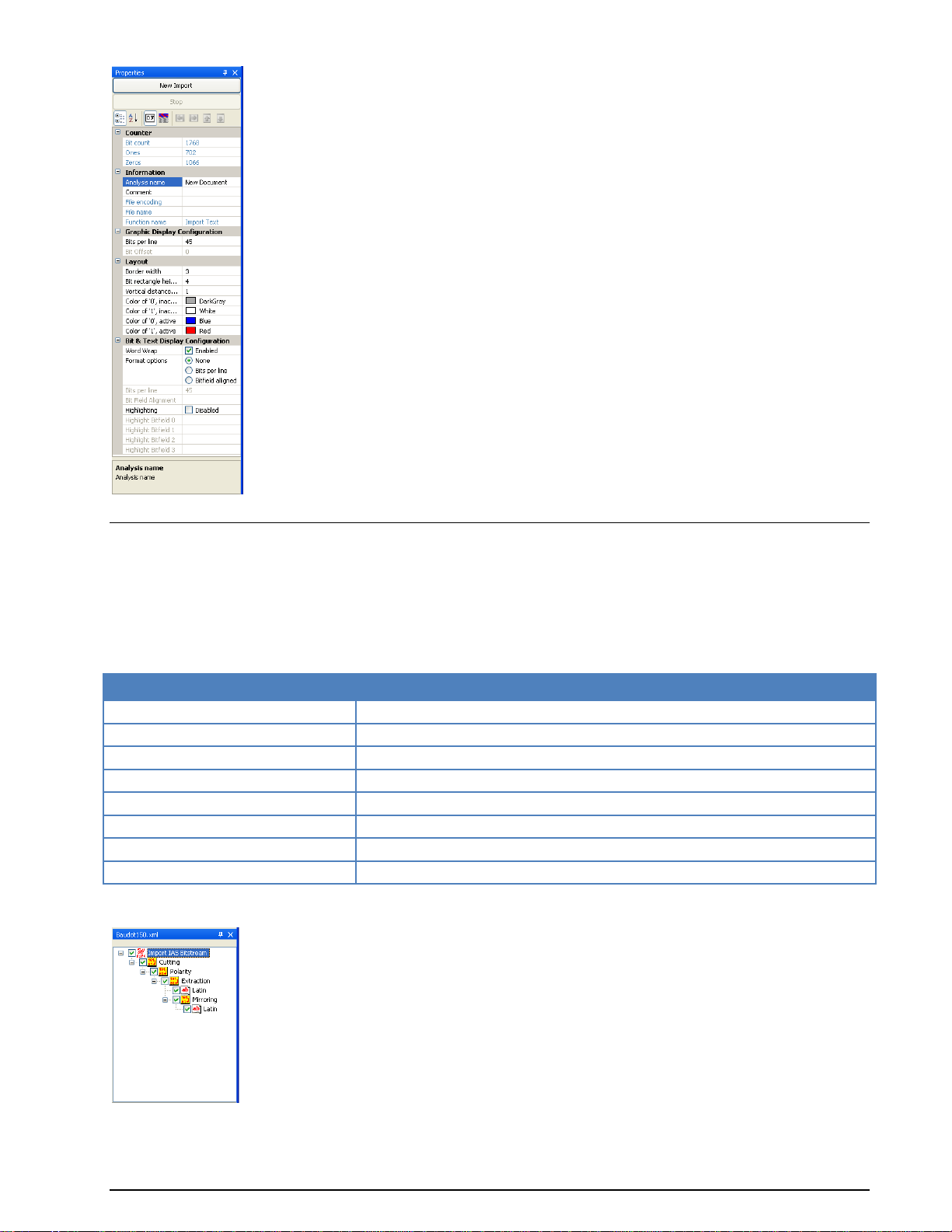
Properties Window
The parameters in the Properties window are grouped into different categories providing the operator
with information about actual parameter settings and - more important - allowing the operator to
configure each function and to add comments.
Detailed information about the selected parameter is displayed in the text area at the foot of the
Properties window.
In the Counter category information on the recorded bit stream, i.e., Bit count, number of logical Ones
and number of logical Zeros is found.
The Information category contains information on the selected source or analysis set, i.e., Analysis
name, Comments (user input possible), File name (information only) and Function name (information
only). Clicking the function name displays a brief description of the function.
16 Menu BitView Manual V2.5.00 WAVECOM W-BV
Page 23
Keyboard button
Function
No keyboard button pressed
Move and add dragged function
CTRL pressed
Copy and add dragged function
ALT pressed
Move and add dragged function plus all sub-functions
SHIFT pressed
Move and insert dragged function
CTRL and ALT pressed
Copy and add dragged function plus all sub-functions
CTRL and SHIFT pressed
Copy and insert dragged function
SHIFT and ALT pressed
Move and insert dragged function plus all sub-functions
SHIFT/CTRL/ALT pressed
Copy and insert dragged function plus all sub-functions
History Explorer Window
The History Explorer window provides a quick overview of the current analyzing process. It allows the
operator to try out different function paths with different parameter settings and enables instant
comparison of the results of these trials.
Functions may be re-arranged and deleted using the mouse pointer (drag-and-drop with left mouse button
pressed and held) in combination with the modifier buttons (CTRL, ALT, SHIFT) or the mouse right-click
menu.
When one of the modifier buttons is pressed while dragging, detailed information is displayed on top of the
window.
If the History Explorer window has been hidden a list of functions applied is still available by clicking the
arrow button in the top right corner of a document window.
BitView Manual V2.5.00 WAVECOM W-BV Menu 17
Page 24
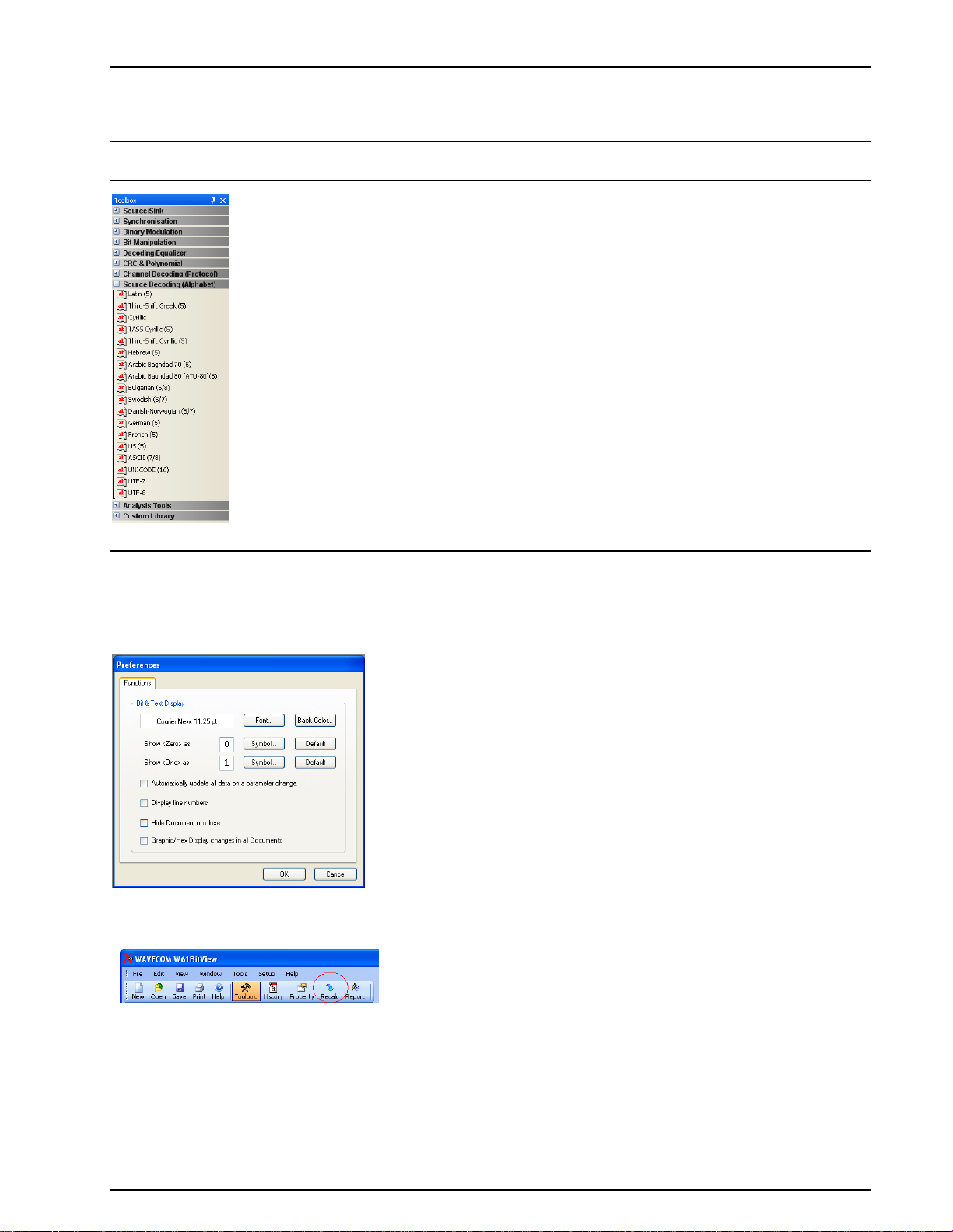
Toolbox Window
The Toolbox menu is divided into libraries, and each library contains one or more functions.
Note: The Custom Library is not visible unless a custom function has been added. The Analysis Tools
are not added to the History Explorer tree and are not persistently stored.
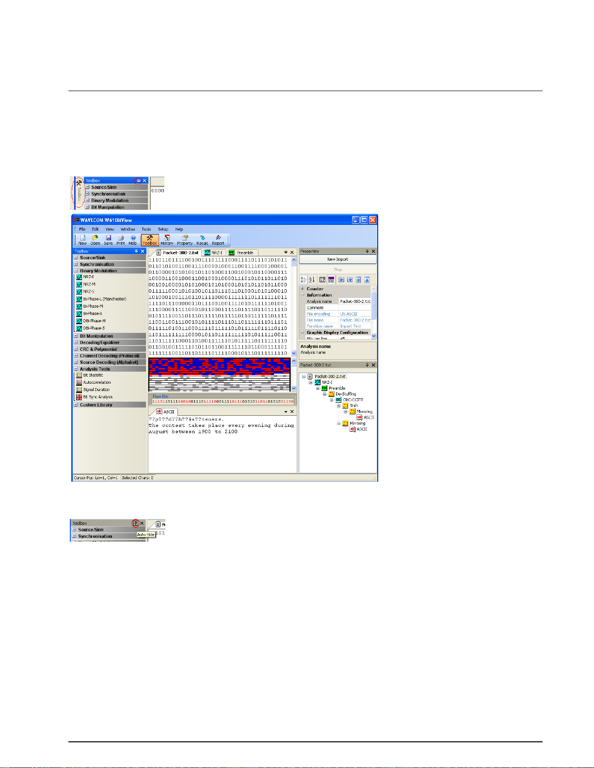
Preferences
The Preferences dialog box may be selected from the Setup menu.
Substitution symbols for logical zero and logical one may be directly edited or selected using the
appropriate Symbol button.
If Automatically update all data on a parameter change is ticked, all functions are automatically
recalculated when the operator changes a parameter. Uncheck the tick box if this behavior is not
desirable, and use the Recalc button in case a recalculation is necessary.
If Hide document on close is ticked, a document is hidden when closed, but remains in the History
Explorer. Clicking the function associated with the document in the History Explorer will make the
document visible again.
To remove the function completely, select the appropriate function in the History Explorer and press the
Delete key on your keyboard.
If this option is not checked, documents are completely removed when closed. Closing the root document
will close and remove all other functions and their associated documents.
18 Menu BitView Manual V2.5.00 WAVECOM W-BV
Page 25
If Graphic/Hex display changes in all documents option is selected, all the documents will have the
same display settings, i.e., if the display is changed from graphic to hex in one document, and all other
documents will change their display type as well.
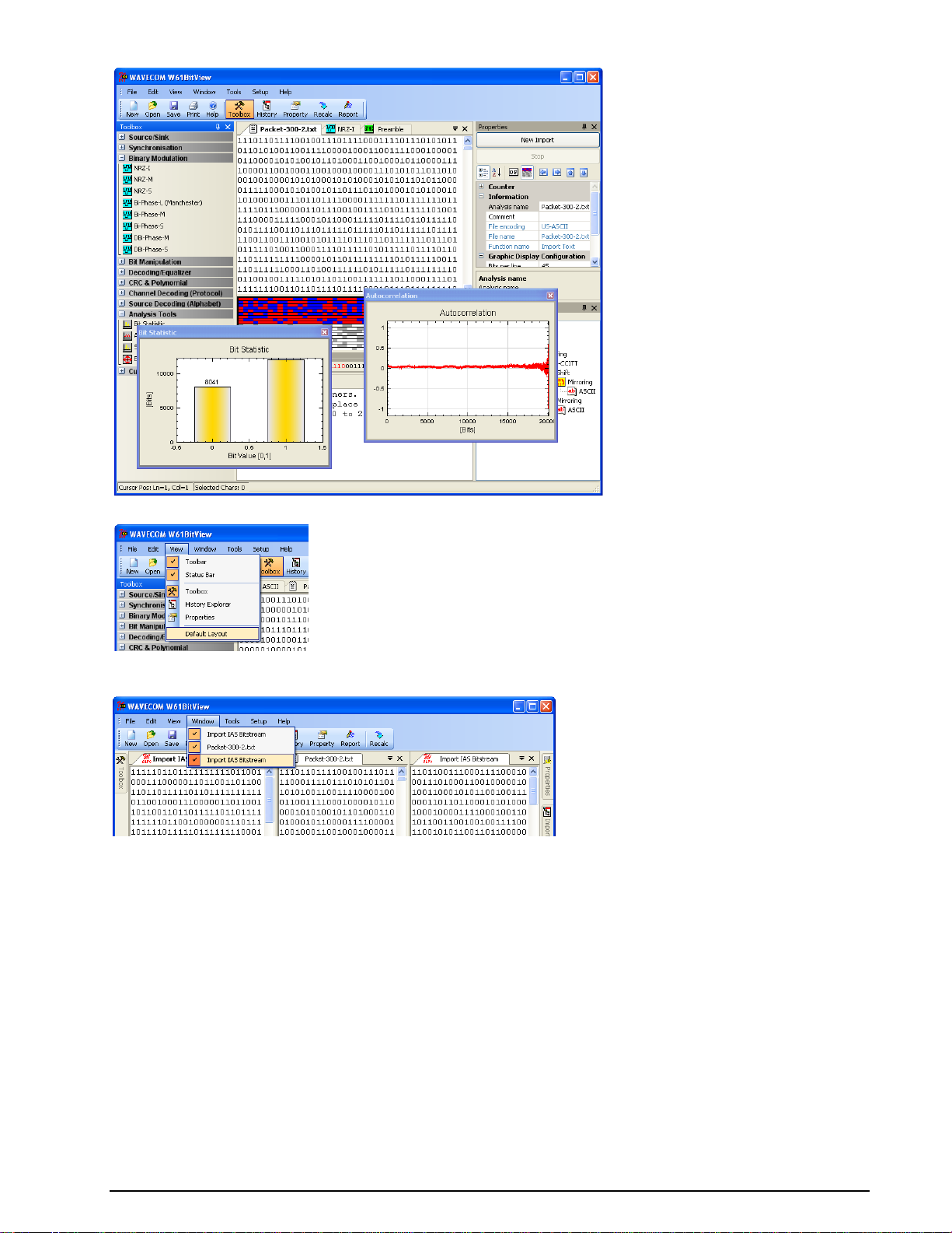
Layout Settings
At run time, the user can drag and drop all windows to re-arrange them according to the preferred layout
when not in auto-hide mode (map pin icon on window top line must be in vertical position). In the
selected window press and hold the left mouse button and drag the window to the position you want it be
in or just double-click the window and it will detach itself.
In addition the Parameters, History Explorer and Toolbox windows use auto-hide functionality. To
activate auto-hide for a window, click the map pin icon on the upper window line. The icon will change
from vertical to horizontal position.
The window is now hidden and a tab with its name appears on the side of the application window. To
make the window appear, move the cursor to the tab. To hide the window again, double-click on the
window.
To restore the application default layout, in the menu bar click View > Default Layout.
BitView Manual V2.5.00 WAVECOM W-BV Menu 19
Page 26
Use View > Default Layout to use or restore the default layout of the windows.
More than one Analysis Set may be active at a time. Using the Window menu allows the user to show or
hide these Analysis Sets.
The layout and display settings can be configured from the upper part of the Properties window.
20 Menu BitView Manual V2.5.00 WAVECOM W-BV
Page 27
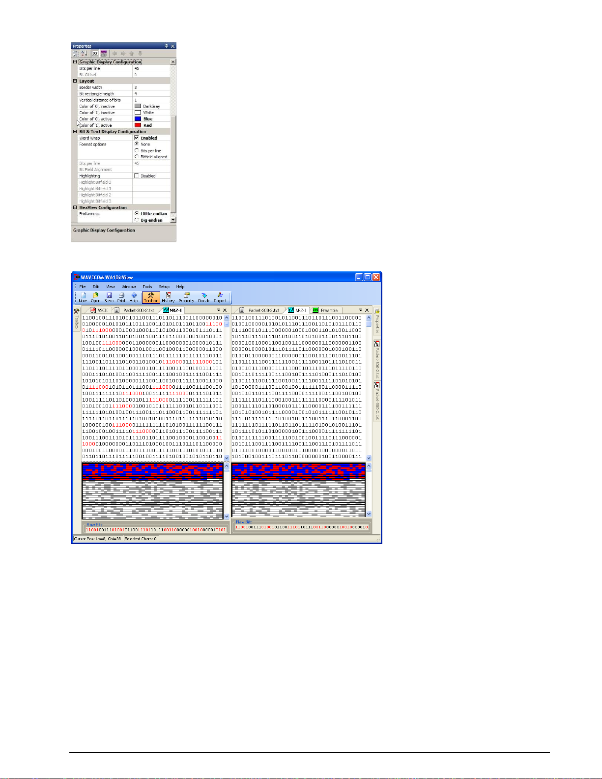
Using the Bit & Text Display Configuration category in the Properties window enables the operator to
use different display format options listed below.
Word Wrap
Checking the Word Wrap Enabled tick box enables word wrapping in the bit and text document.
Bits per line
This parameter allows displaying a specific number of bits per line. Choose the Bits per line radio button
under Format Options to enable this feature.
Bit Field Alignment
Whenever the specified bit pattern is found in the bit stream, a new line is started, i.e., a line break is
inserted. Choose the Bitfield aligned radio button under Format Options to enable this feature.
Highlighting
The bit stream is searched for a specific bit pattern and when found the pattern is marked. A maximum of
four different search patterns are possible. Check the Highlighting check box to enable this feature and
enter the search patterns in the appropriate text fields.
BitView Manual V2.5.00 WAVECOM W-BV Menu 21
Page 28
Display options
In addition to the document window(s), two additional views of the bit stream being analyzed are
available at the bottom of the document window(s): one is a graphical display and the other one a
hexadecimal display.
Graphic Display
A graphic display is associated with the bit stream and may be selected from the top of the Properties
window clicking the Show Graphics bit view icon.
The vertical size of the graphic display can be changed by dragging its top border.
The Layout category let you change the appearance of the graphic display.
In the Graphic Display Configuration category the number of bits per line can be set. This feature can
be used to find periodic bit patterns in the bit stream by changing the number of bits per line until a
repeating bit pattern is visible. It is much easier to find those patterns using the graphic display than to
use the hex display.
The arrow buttons on top of the Properties window are designed to move the active selection in the
graphic display. The selected bits are displayed as Raw Bits in the bottom of the graphic display.
When the cursor is placed in the graphic display, the cursor changes into a cross hair and a context
window indicates the position of the cursor (offset, row and column). Holding the right mouse button
allows the user to zoom in on the selected area. Right-clicking will make an Unzoom button appear. Use
this button to un-zoom the selected area.
It is possible to zoom into the graphic display. Hold the left mouse button down and select the area that is
to be expanded. A right click on the graphic display shows the context menu for un-zooming the view.
Hex Display
A hex display may be selected by pressing the Show Hex view button on top of the Properties window.
This display option offers a standard hex dump layout consisting of an offset in hexadecimal notation,
hexadecimal characters separated by a space and finally the data in ASCII characters.
The interpretation of 8-bit frames can be toggled between Little and Big endian in Hex View
Configuration, Endianness, i.e., “00101100” is displayed as 0x34 when interpreted as little endian and
as 0x2c when interpreted as big endian.
Printer Dialog
22 Menu BitView Manual V2.5.00 WAVECOM W-BV
Page 29
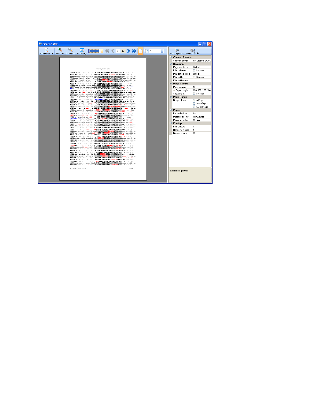
The printer dialog is used for print preview and the printer settings. Use it by clicking the Print button or
by selecting the menu entry File > Print. All layout settings, i.e., highlighting, alignment or bits per line,
are supported.
Function Library
Common Functions
Auto-Calculation
To test a hypothesis regarding the properties of a bit stream, the operator may wish to test a property
within a specific range of values. This task can either be conducted by changing the parameter value
manually and then checking the outputs one by one or it can be performed automatically. That is where
Auto-Calculation comes into play.
A right click on the parameter name (not the value) in the parameters window opens a context menu.
Click Reset to change parameters to their default values or click AutoCalc Setup to open the Auto-
Calculation window:
BitView Manual V2.5.00 WAVECOM W-BV Function Library 23
Page 30
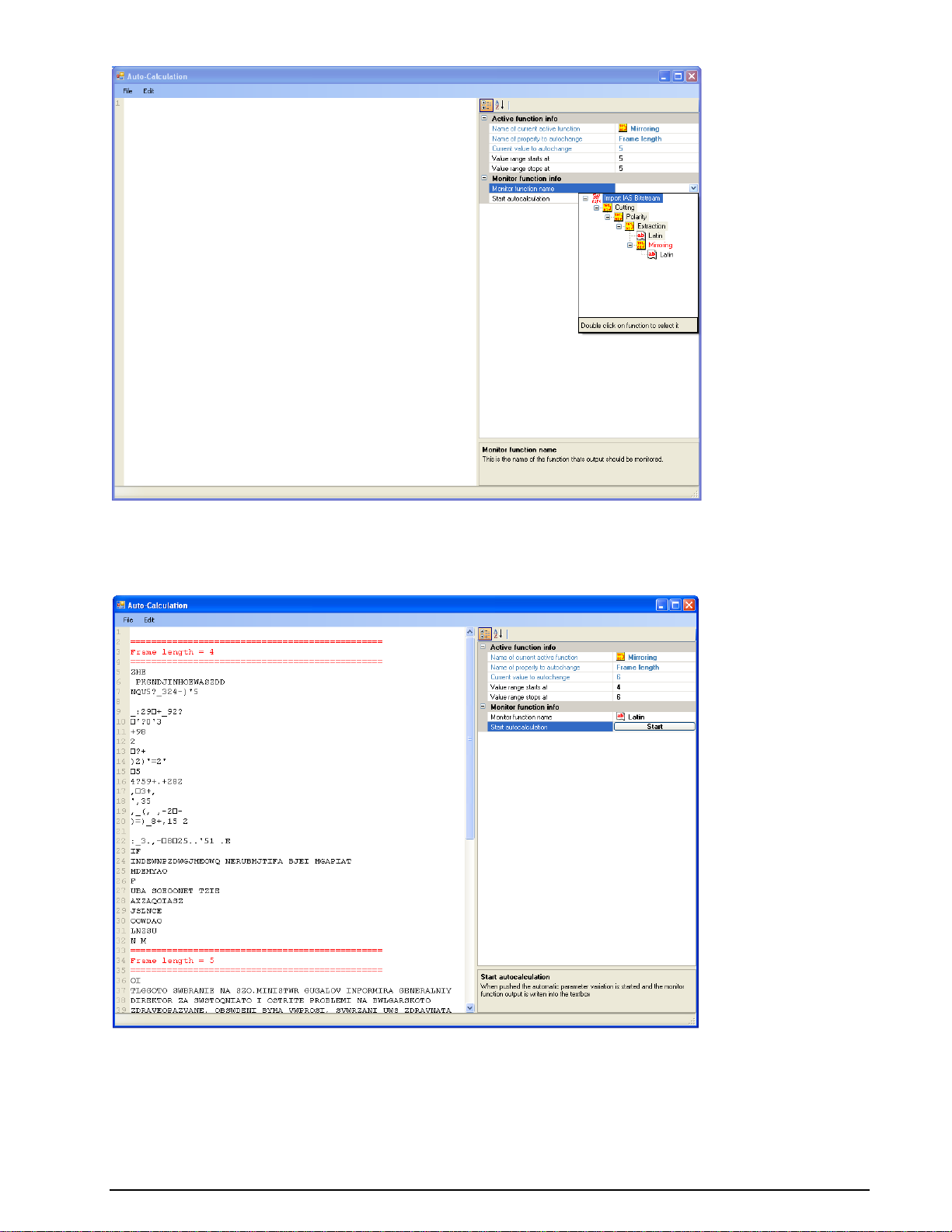
Start and stop values for the selected parameter must be chosen using the Value range starts at and
Value range stops at parameters. The auto-calculation function then needs to be told which function will
monitor the calculation output by use the function drop-down menu of the Monitor function name
parameter – the function MUST be lower in the function tree as displayed in the History window.
Automatic calculation can now be started by clicking the Start button.
The result of the auto-calculation is displayed in the left side of the Auto-Calculation window. Edit >
Quick find can be used for searching the auto-calculated output.
24 Function Library BitView Manual V2.5.00 WAVECOM W-BV
Page 31

Enable or Disable Functions
Functions in the analysis tree can easily be enabled or disabled by checking or un-checking the checkbox
next to the function in the History Explorer.
Progress Calculator
A small window will open whenever a calculation is taking place informing the user of the progress of the
process.
Source/Sink
Bit streams stored in text files may be imported and differently interpreted according to the three file
conversion formats available. A real-time bit stream will always be interpreted as binary ones and zeros.
Import Text Data
Input: Off-line bit stream
BitView Manual V2.5.00 WAVECOM W-BV Function Library 25
Page 32

Function:
Imports a bit stream from a text file. Only ASCII ones (“1”, 0x31) and zeros (“0”, 0x30) are considered as
valid characters, others values are ignored.
Example: “0110w700” is imported as “011000”.
Import Hex Data
Input: Off-line bit stream
Function:
Imports a bit stream from a text file. Only ASCII figures from “0” (0x30) to “9” (0x39) and letters from
“A” (0x41) or ”a” (0x61) to “F” (0x47) or ”f” (0x67) are considered as valid characters, others values are
ignored.
Example: “a1bg0c1kd0” is imported as “10100001101100001100000111010000”
Import Binary Data
Input: Off-line bit stream
Function:
Imports a bit stream form a text file. All 8 bit ASCII characters”(0x00…0xFF) are considered as valid
characters.
Example: “Ka1Z<” is imported as “0100101101100001100111000011000101011010”
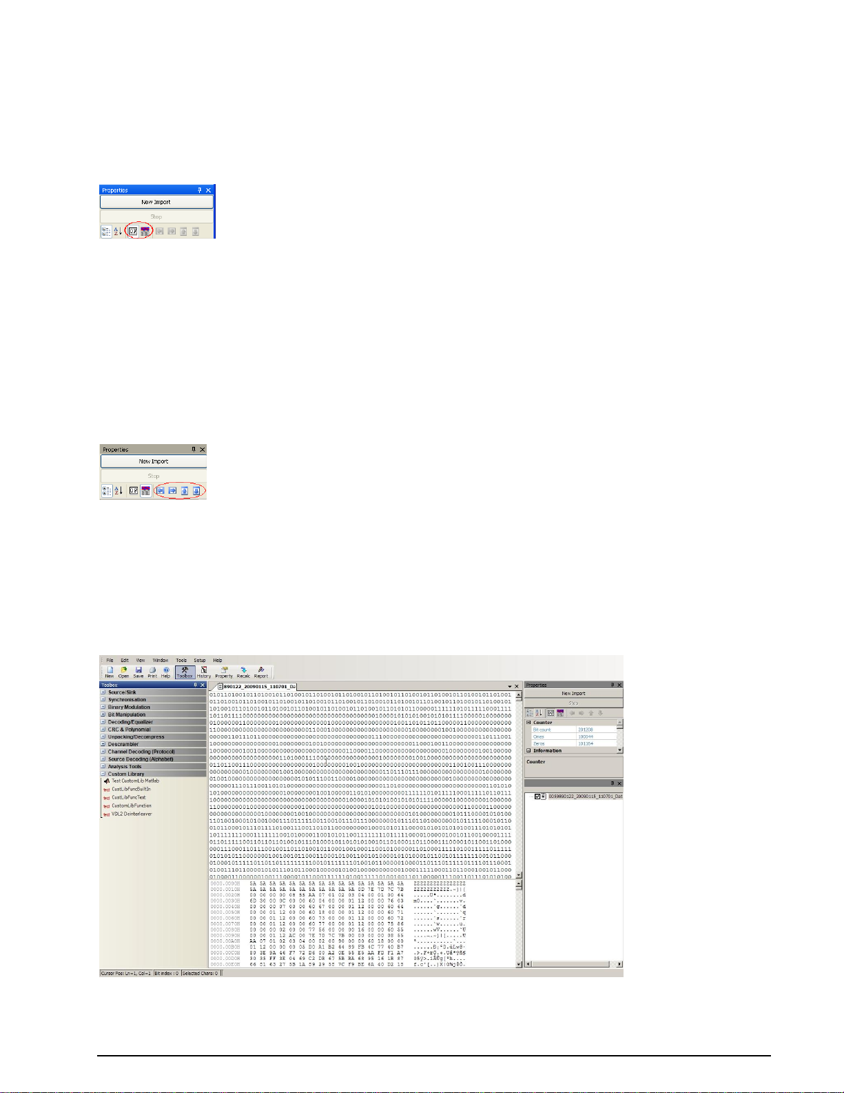
Import IAS Bitstream
Input: Real-time bit stream
Function:
Directly transfers a real-time bit stream from WAVECOM Server, the application that manages
WAVECOM decoder cards. The transfer takes place via the XML Remote Control Interface of the server.
Before starting a bit stream import into BitView, the desired mode must be started in the WAVECOM
decoder.
In order to be able to connect to the server, the following settings are required:
26 Function Library BitView Manual V2.5.00 WAVECOM W-BV
Page 33

Parameter
Value
Import Server Selection
W61PC Server or W-CODE Server
RCI Timeout [s]
Maximum time in seconds to establish a connection to WAVECOM server. If a connection to
the server could not be established within this period of time, the application cancels the
connection procedure
Recording Duration
Enter the desired duration of the recording in seconds. ‘0’ means infinite
Card/Device Number
For W51/W61 enter the decoder card number. For W-PCIe, W-PCI and W-CODE enter the
device number. These numbers are found in the decoder Setup menu
Decoder Bitstream
Type
This command will configure WAVECOM Server to run code appropriate to the selected decoder mode. The choices are: HF (default setting), VHF- Direct or VHF-Indirect. For W-
CODE Server HF STANAG-4285 is available
IP address
Enter the IP address or MS computer name of the PC that hosts WAVECOM Server. Default
is 127.0.0.1, which must be used for a WAVECOM decoder and BitView installed on the
same host
Port Number
Enter the port number of the XML Remote Control Interface (RCI) of WAVECOM Server.
Default is port 33244 (see WAVECOM Server Control | Networking Information)
To start importing press the New Import button on top of the Properties window. The document
window will display Recording…. and the same text will be displayed blinking in the display bottom line.
The WAVECOM decoder screen will display Sending bitstream to external application…
To stop importing press the Stop button on top of the Properties window. After importing of an IAS bit
stream has been stopped, the Bit Sync Analysis/Import IAS Bitstream function automatically opens.
Stopping the BitView import will not stop the decoder bit stream, nor will a decoder detect that the
BitView Tool has been closed. Similarly BitView will not detect that the selected decoder mode has been
closed.
If BitView cannot establish a connection with WAVECOM Server the Recording… status indication will
disappear.
Export Text Data
Input: Current document window contents
Output: Text file
Function:
Write the contents of the current document to a text file. A Save As dialog will appear from which to
select a filename and a folder for the exported file.
Generate Pseudo-Noise
Input: Parameters
Output: Pseudo-random noise bit sequence
BitView Manual V2.5.00 WAVECOM W-BV Function Library 27
Page 34

Function:
Generate a pseudo-random noise symbol sequence using a linear feedback shift register initialized with a
bit pattern (seed). The shift register is configured by clicking the Noise Generator Configuration field.
Clicking the drop-down list will open a shift register schematic with 16 stages, each representing in
increasing order the elements of the characteristic polynomial of the shift register:
A click in the check box for each stage enables that bit (the initial term x0 = 1 is omitted). Clicking a stage
box will toggle its initial state between 1 and 0. When configuring the shift register setting is complete
click Ok to save the configuration, which is displayed in the Characteristic polynomial and Initial shift
register state fields.
The Number of Symbols determines the length of the pseudo noise output string.
The shift register output bits are mapped to symbols defined by Symbol for bit = 0 and Symbol for bit
= 1. The settings must reflect the specific coding of the mode for which the sequence is generated, e.g.,
for STANAG-4285 the settings must reflect the values of the transcoding tables of STANAG-4285 (see
custom function “Symbol Transcoding”).
When configuration is finished, press the Generate Pseudo-Noise buttonto generate the desired
sequence – pressing Stop terminates the generator. The generated string appears in the document
window as well as in the graphical display and as a line of raw bits.
This function allows the user to automatically generate a correct shift register based bit sequence and
then use it as a search string by pasting the generated sequence into one of the Highlighting text bins
(Highlighting Bitfield 0 … 3) in the Bit & Text Display Configuration category.
Synchronization
Preamble
In: Bit stream
Out: Bit stream
28 Function Library BitView Manual V2.5.00 WAVECOM W-BV
Page 35

Function:
Searches for the Preamble value in the incoming bit stream and then writes the number of Bits after
Preamble to the output. If the bit stream contains more than one preamble, the parameter Ignore
preambles can be set for the function to skip a certain number of preambles.
Binary Modulation
NRZ-I
In: Bit stream
Out: Bit stream
Function:
Changes the bit stream according to the “Non Return to Zero Inverse” (NRZ-I) decoding scheme, where
no bit change represents a ‘1’ and a bit change represents a ‘0’.
NRZ-M
In: Bit stream
Out: Bit stream
Function:
Changes the bit stream according to the “Non Return to Zero Mark” (NRZ-M) decoding scheme, where a
bit change represents a ‘1’ and no bit change represents a ‘0’.
NRZ-S
In: Bit stream
Out: Bit stream
BitView Manual V2.5.00 WAVECOM W-BV Function Library 29
Page 36

Function:
Changes the bit stream according to the “Non Return To Zero Space” (NRZ-S) decoding scheme, where no
bit change represents a ‘1’ and a bit change represents a ‘0’.
Note: This function is identical to NRZ-I.
Bi-Phase-L (Manchester)
In: Bit stream
Out: Bit stream
Function:
Analyze the bit changes of the bit stream. A change from ‘1’ to ‘0’ represents a ‘1’ and a change from ‘0’
to ‘1’ represents a ‘0’. The bits are analyzed in pairs, i.e., the number of output bits is half the number of
input bits.
Bi-Phase-M
In: Bit stream
Out: Bit stream
Function:
In Bi-Phase-M encoding, a logical ‘1’ is represented by a pair of bits of opposite values (‘10’ or ‘01’). A
logical ‘0’ is represented by a pair of bits of the same values (‘00’ or ‘11’). The decoding procedure halves
the number of output bits.
Bi-Phase-S
In: Bit stream
Out: Bit stream
30 Function Library BitView Manual V2.5.00 WAVECOM W-BV
Page 37

Function:
In Bi-Phase-S encoding, a logical ‘0’ is represented by a pair of two bits of opposite values (‘10’ or ‘01’). A
logical ‘1’ is represented by a pair of bits of the same value (‘00’ or ‘11’). The decoding procedure halves
the number of output bits.
DBi-Phase-M
In: Bit stream
Out: Bit stream
Function:
Two bits form a bit period. A bit change at the beginning of a bit period represents a ‘0’, while no bit
change at the beginning of a bit period represents a ‘1’.
DBi-Phase-S
In: Bit stream
Out: Bit stream
Function:
Two bits form a bit period. A bit change at the beginning of a bit period represents a ‘1’, while no bit
change at the beginning of a bit period represents a ‘0’.
BitView Manual V2.5.00 WAVECOM W-BV Function Library 31
Page 38

Bit Manipulation
De-Stuffing (HDLC)
In: Bit stream
Out: Bit stream
Function:
Removes stuff bits inserted in the input bit stream. If a zero bit is detected after five contiguous Ones, the
Zero bit will be removed.
Example: “111101” is changed to “111111”.
Mirroring
In: Bit stream
Out: Bit stream
Function:
The mirroring function modifies the incoming bit stream frame by frame. The Frame length is user
defined. The function changes the bit order within each frame.
Example with a frame size of 5 bits:
“10111 01101” is changed to “11101 10110”.
Rotation
In: Bit stream
Out: Bit stream
Function:
32 Function Library BitView Manual V2.5.00 WAVECOM W-BV
Page 39

Example:
#1
#2
#3
Bits to change polarity
111000111
1 0 Input
111111111000000000
111111111000000000
111111111000000000
Output
000111000111000111
000000000111111111
111111111000000000
The rotation function modifies the incoming bit stream frame by frame. The Frame length is user
defined, as well as the Rotation direction and the Number of bits to be rotated.
Example with a frame size of 5 bits, left rotation direction and one rotation step:
“10111 01101” is changed to “01111 11010”.
Shift
In: Bit stream
Out: Bit stream
Function:
The shift function modifies the incoming bit stream frame by frame. The Frame length is user defined, as
well as the Shift direction, the Number of bits to be shifted and the Fill bit value.
Example with a frame size of 5 bits, left shift direction, two bits shift and a fill value of ‘1’:
“10111 01101” is changed to “11111 10111”.
Polarity
In: Bit stream
Out: Bit stream
Function:
Invert the bit stream according to the Bits to change polarity pattern. At positions marked with a “1”,
the bit is inverted, at positions with a “0”, the bit remains unchanged.
De-Interleaving Block
In: Bit stream
Out: Bit stream
BitView Manual V2.5.00 WAVECOM W-BV Function Library 33
Page 40

Example:
#1
#2
Block Length
12
16
Frame Length
1
2
Interleaving Distance
3
2
Input
000111000111
0011001111100010
Matrix
000
111
000
111
00 11
00 11
11 10
00 10
Output
010101010101
0000110011111010
Function:
Change the bit order according to the settings of Block length, Frame length and Interleaving
distance. The easiest way to understand the de-interleaving function is a closer look at the examples
below (imagine that the bit stream is written horizontally into the buffer and read out vertically):
De-Interleaving Stream
In: Bit stream
Out: Bit stream
Function:
Change the bit order according to the settings of Offset into Bit Buffer, Output frame length and
Interleaving distance.
The Offset into Bit Buffer tells the function where to start the de-interleaving function. Is Offset into
Bit Buffer for example set to 3, then the first 3 bits will not be used for calculation of the output data.
According to the Output frame length setting, the output data will be less than the input data. The
easiest way to understand the de-interleaving stream function is a closer look at the example below
(imagine that the bit stream is written horizontally into the buffer and read out vertically):
Example 1:
Offset into Bit Buffer = 0
Interleaving distance = 15
Output frame length = 4
34 Function Library BitView Manual V2.5.00 WAVECOM W-BV
Page 41

Example 2:
Offset into Bit Buffer = 3
Interleaving distance = 8
Output frame length = 4
AND / OR / XOR / NOT
In: Bit stream
Out: Bit stream
Function:
The output bit values depend on the selected logical operation (Logical operator) performed on the input
bits. The first operand is the input bit stream, while the second operand (Frame) is constant and can be
either ‘0’ or ‘1’.
AND / OR / XOR / NOT Range
In: Bit stream
Out: Bit stream
Function:
The output bit values depend on the selected logical operation (Logical operator) performed on the input
bits from Offset to first frame and over Number of frames. The first operand is the input bit stream,
while the second operand (Frame) is constant and can be ‘0’ or ‘1’.
BitView Manual V2.5.00 WAVECOM W-BV Function Library 35
Page 42

Extraction (Mask)
In: Bit stream
Out: Bit stream
Function:
Extracts bits from the incoming bit stream using the user defined Mask. Only positions marked with a ‘1’
are extracted. The output bit stream is calculated frame by frame.
Example: “111110” with mask “110” changes to “1111”.
Extraction (Range)
In: Bit stream
Out: Bit stream
Function:
Extract Extraction length bits from the incoming bit stream starting at Extract start position.
Cutting
In: Bit stream
Out: Bit stream
Function:
Cuts Cut length bits, beginning at Cut start position. Note that counting starts at zero, i.e., the first
element in the bit stream is number 0.
36 Function Library BitView Manual V2.5.00 WAVECOM W-BV
Page 43

Parameter
Constraint length
Equals K, where K is the number of memories of the shift register in the encoder
Decision best state
Use best state or not
Last decoder state
Initial state of the decoder
Metric
Select hard or soft decision
Mode
Select whether the input data should be treated as a continuous stream or a stream of
bursts.
Soft decision bits
If soft decision is used, enter the number of soft decision bits
Parameter
Value
Frame
Bits are inserted according to the entered bit pattern. The length of the bit pattern corresponds to the frame length. At positions marked with a ‘0’, a bit is inserted. Additionally, for
every input bit, a probability bit is added. For received bits (marked with a ‘1’ in the frame
pattern), a ‘1’ probability bit is added - for inserted bits, a ‘0’ probability bit is added (equals
a probability of 0.5)
Decoding/Equalizer
Viterbi-Decoding
In: Bit stream
Out: Bit stream
Function:
Decode the incoming bit stream using the Viterbi algorithm - a maximum-likelihood decoding procedure
for convolutional codes.
De-Puncturing
In: Bit stream
Out: Bit stream
Function:
This function adds de-puncturing and probability bits to the input bit stream.
Example with a frame pattern of “110”:
The frame pattern “110” means that after two input bits, a de-puncturing bit must be inserted so “1111”
becomes “111100111100”.
BitView Manual V2.5.00 WAVECOM W-BV Function Library 37
Page 44

Parameter
Description
Code rate (Standard
matrices)
Defines code rate for de-puncturing. If the code rate is ½ there is no puncturing. All
other code rates require de-puncturing
Select depuncture
matrix
Selects the type of de-puncture matrix used
User defined matrix
Selects the number of de-puncture matrix columns
Code rate
Puncturing matrix
1/2
1/1 (no puncturing)
2/3
10/11
3/4
101/110
4/5
1000/1111
5/6
10101/11010
6/7
100101/111010
7/8
1000101/1111010
Code rate
Viterbi decoder settings
Metric
No. of decision bits
1/2
Hard decision
N.A.
All other rates
Soft decision
3
Standard Depuncturing
In: Punctured bit stream
Out: De-punctured bit stream
Function:
This function adds de-puncturing and probability bits to the input bit stream according to standard
puncture matrices or a user defined matrix. The input stream is converted so that each input bit is
followed by three probability bits within the range “0 … 7”, where “0” indicates an erasure and “7” a
probability of 100%.
The standard puncturing matrices for selected code rates:
Decoding the de-punctured bit stream can be done by using the Viterbi decoder configured as listed
below:
Difference-Decoding
In: Bit stream
Out: Bit stream
38 Function Library BitView Manual V2.5.00 WAVECOM W-BV
Page 45

Parameter
Description
Corrected errors
Number of corrected errors
Error Positions
Positions of detected errors
Generator Polynomial
Encoding generator polynomial on the form g(x) = 111…
Minimum distance
This property determines the number of detectable errors and the number of correctable
errors
Number of frames
Number of frames in the decoded bit stream
Order of Galois field
Property of the field of numbers to which a given BCH code belongs
Original data length
Length of original code word
Primitive polynomial
A polynomial describing a given BCH code
Parameter
Description
Value
BCH algorithm
Algorithm used to find BCH polynomial
Berlekamp-Massey, Euclid
Code word length
Length of code word including redundancy
bits.
Max errors
Error correction capability
Function:
This function performs difference decoding, which is a logical XOR operation on the previous output bit
and the current input bit. The Start bit value is user defined.
Example with start bit value of ‘1’:
“01101110” is changed to “10110100”.
BCH-Decoding
In: Bit stream
Out: Bit stream
Function:
Decodes BCH encoded bit streams.
The function returns the parameters listed in the table below.
BitView Manual V2.5.00 WAVECOM W-BV Function Library 39
Page 46

Parameter
Description
Alphabet size
Size of input alphabet
Block code type
Type of block code used
Codeword length
estimation
Length of input code word (n) , i.e., number of data bits (k) plus number of checksum bits
(n-k)
Generator polynomial
Generator polynomial (G(x)), i.e., the polynomial used to generate the checksum
Input length
Estimated number of data bits per code word
Rate estimation
Code rate (R = k/n), i.e., ratio between number of data bits (k) and total number of bits
per frame (n+k)
Example with code length 15 and error correction capability 3:
“011001010000111” is changed to “00111”.
Block Code Analysis
In: Bit stream
Out: Bit stream
Function:
Identify forward error correction block codes like BCH, RS, CRC or Hamming.
The function returns alphabet size (normally equal to 2 because input is a binary bit stream), block code
type (BCH, RS, etc.), code word length estimation (n), generator polynomial, input length estimation (k)
and code rate estimation (R = k/n).
The function will identify the following Block Code Types,
BCH
CRC or perfect cyclic code
Binary repetition (reversals)
Binary Golay
Binary Hamming
CRC block code
Non-cyclic block code
Unidentified code
The generator polynomial is returned as a string of ones and zeros, starting at the lowest order of 2^x,
e.g., 1001110010101 means 1 + x^3 + x^4 + x^5 + x^8 + x^10 + x^12.
The results of the analysis are displayed in a new document window and in the Calculation category in
the Properties window. The table below lists the calculated parameters.
Constraints: Frames must have equal length and if the bit stream is delimited by flags they must be
removed with the Extract or Cut functions.
Convolutional Code Analysis
In: Bit stream
Out: Bit stream
40 Function Library BitView Manual V2.5.00 WAVECOM W-BV
Page 47

Parameter
Description
Gen. Poly1
Generator polynomial 1 found
Gen. Poly2
Generator polynomial 2 found
Gen. Poly3
Generator polynomial 3 found
Gen. Poly4
Generator polynomial 4 found
Input bits (k)
Number of input bits to convolutional encoder
Constraint length
(K)
Constraint length, i.e., the number of bit in encoder memory affecting the generation of n
output bits
Output bits (n)
Number of output bits from convolutional encoder
Function:
Find the parameters of convolutional encoded bit streams.
The function returns constraint length (K), number of input bits per shift cycle (k), number of output bits
per shift cycle (n) and generator polynomials. The function will search for K = 2..14, and n = 2..4. The
numbers of returned generator polynomials depend on the number of output bits per shift cycle (n).
The results of the analysis are displayed in a new document window and in the Calculation category in
the Properties window. The table below lists the calculated parameters.
General Reed Solomon Decoding
In: Bit stream
Out: Bit stream
Function:
Decodes bit streams which are encoded with a Reed-Solomon code.
The decoder must be configured by the parameters listed below.
BitView Manual V2.5.00 WAVECOM W-BV Function Library 41
Page 48

Parameter
Description
Value
Length of data
(k)
Number of data symbols in a code word, where the number of data
bits (k) is less than the total number of bits (k), i.e., k < n
Number of parity
symbols
Number of parity symbols in a code word (n-k)
Output with Parity Symbols
Specifies if parity symbols should be included in the output
Yes, No
Position of Parity
Symbols
Specifies if parity symbols are leading or trailing the code word
End of code word,
Beginning of code
word
Primitive polynomial
Encoding polynomial
Select from dropdown list
Root for generator polynomial
Root for generator polynomial. See parameter help desk for further
explanation
Parameter
Description
Frames with corrected errors
Number of frames with correctable errors
Frames with decoding failures
Number of frames with decoding errors
Frames without errors
Number of frames without errors
m (bits per symbol)
Number of bits per symbol (m)
n (max. length of code word)
Maximum number of symbols per code word. N is derived from the selected
primitive polynomial
Number of decoded frames
Number of decoded frames
The results of the analysis are displayed in the Calculation category in the Properties window. The table
below lists the calculated parameters.
CRC & Polynomial
CRC (1..32)
In: Bit stream
Out: Bit stream
Function:
Calculate the cyclic redundancy checksum (CRC) value of the input bit stream according to the settings
described below.
42 Function Library BitView Manual V2.5.00 WAVECOM W-BV
Page 49

Parameter
Value
Augment Zero Bits
Calculate CRC with or without augmented (added) zero bits
CRC Bits Appended
Are CRC bits appended to the bit stream (Yes or No)
Final XOR Value
Final XOR value in hex
Initial Value
Initial value in hex
Order
Polynomial order (1..32)
Polynomial
Polynomial in hex
Reverse Data Bytes
Reflect data byte before processing (Yes or No)
Reverse Result Before XOR
Reflect final result before XOR (Yes or No)
The calculated CRC value is displayed in the Calculated CRC field. If CRC Bits Appended is set to ‘Yes’,
then the Transmitted CRC field contains the transmitted CRC value in hex format. If there are no
appended CRC bits, then the Transmitted CRC field has no meaning. The transmitted CRC value is also
displayed in inverted format (Transmitted CRC Inverse).
CRC-8
In: Bit stream
Out: Bit stream
Function:
Calculate the standard CRC-8 values of the incoming bit stream.
The calculated CRC value is displayed in the Calculated CRC field. If CRC Bits Appended is set to Yes,
then the Transmitted CRC field contains the transmitted CRC value in hex format. If there are no
appended CRC bits, then the Transmitted CRC field has no meaning. The transmitted CRC value is also
displayed in inverted format (Transmitted CRC Inverse).
CRC-10
In: Bit stream
Out: Bit stream
BitView Manual V2.5.00 WAVECOM W-BV Function Library 43
Page 50

Function:
Calculate the standard CRC-10 values of the incoming bit stream.
The calculated CRC value is displayed in the Calculated CRC field. If CRC Bits Appended is set to Yes,
then the Transmitted CRC field contains the transmitted CRC value in hex format. If there are no
appended CRC bits, then the Transmitted CRC field has no meaning. The transmitted CRC value is also
displayed in inverted format (Transmitted CRC Inverse).
CRC-12
In: Bit stream
Out: Bit stream
Function:
Calculate the standard CRC-12 values of the incoming bit stream.
The calculated CRC value is displayed in the Calculated CRC field. If CRC Bits Appended is set to Yes,
then the Transmitted CRC field contains the transmitted CRC value in hex format. If there are no
appended CRC bits, then the Transmitted CRC field has no meaning. The transmitted CRC value is also
displayed in inverted format (Transmitted CRC Inverse).
CRC-16
In: Bit stream
Out: Bit stream
44 Function Library BitView Manual V2.5.00 WAVECOM W-BV
Page 51

Function:
Calculate the standard CRC-16 values of the incoming bit stream.
The calculated CRC value is displayed in the Calculated CRC field. If CRC Bits Appended is set to Yes,
then the Transmitted CRC field contains the transmitted CRC value in hex format. If there are no
appended CRC bits, then the Transmitted CRC field has no meaning. The transmitted CRC value is also
displayed in inverted format (Transmitted CRC Inverse).
CRC-CCITT
In: Bit stream
Out: Bit stream
Function:
Calculate the standard CRC-CCITT values of the incoming bit stream.
The calculated CRC value is displayed in the Calculated CRC field. If CRC Bits Appended is set to Yes,
then the Transmitted CRC field contains the transmitted CRC value in hex format. If there are no
appended CRC bits, then the Transmitted CRC field has no meaning. The transmitted CRC value is also
displayed in inverted format (Transmitted CRC Inverse).
CRC-32
In: Bit stream
Out: Bit stream
BitView Manual V2.5.00 WAVECOM W-BV Function Library 45
Page 52

Function:
Calculate the standard CRC-32 values of the incoming bit stream.
The calculated CRC value is displayed in the Calculated CRC field. If CRC Bits Appended is set to Yes,
then the Transmitted CRC field contains the transmitted CRC value in hex format. If there are no
appended CRC bits, then the Transmitted CRC field has no meaning. The transmitted CRC value is also
displayed in inverted format (Transmitted CRC Inverse).
Parity (Even/Odd/Mark/Space)
In: Bit stream
Out: Bit stream
Function:
Calculate the parity of frames.
Enter Frame length and Parity type from the drop-down list.
The function returns Number of faulty frames and Total number of frames in the Calculation
category and in a document window the selected matrix and a list of the processed frames in bit notation
and parity marked as Parity o.k. or Parity error.
Parity from H-Matrix
In: Bit stream
Out: Bit stream
46 Function Library BitView Manual V2.5.00 WAVECOM W-BV
Page 53

Parameter
Description
Value
Data length in code word
Number of data bits in code word
Generate H-matrix
Generate H-matrix
Yes, No
Generator polynomial (standard
format)
Use the drop-list to open a window for entering the
generator polynomial
Example:
1+x+x^2…
Function:
Calculate the parity of frames using H-matrix multiplication.
By clicking the H-matrix setup field a drop-down list appears. Enter the matrix size in the Rows and
Columns fields, then proceed to fill in logical ‘1’ in the appropriate positions of the matrix by left-clicking
the position. A context label indicates the cursor position.
The function returns Number of code words processed in the Calculation category and in a document
window a list of the analyzed frames and the calculated parity bits in bit notation and parity marked as
Parity o.k. or Parity error.
Parity from polynomial
In: Bit stream
Out: Bit stream
Function:
Calculate the parity of frames by generating an H-matrix from the corresponding cyclic linear block code
generator polynomial. The bit stream is then multiplied by the generated H-matrix.
The parameters listed below configure the function:
BitView Manual V2.5.00 WAVECOM W-BV Function Library 47
Page 54

Reverse bit order in data field
Reverse bit order in the data part of code word
Yes, No
Reverse bit order in gen. poly.
Reverse bit order in generator polynomial
Yes, No
Parameter
Description
Code word length
Total length of code word (data and parity bits)
Number of code words
Number of complete code words
Number of code words with error
Number of code words with bad parity
The function returns these parameters:
Unpacking/Decompress
Unzip
In: bit stream
Out: bit stream
Function:
The unzip function decompresses a ZIP archive from the input bit stream using the standard DEFLATE
algorithm.
If the function is able to detect compressed files in the bit stream, the names of these files is shown in the
Files in Archive field.
The output of this function can be processed further by using other functions or can be saved into files.
The Unzip to disk function is started by pressing the Start button. If a password is required enter it in
Password. A file dialog will appear to select the folder for the decompressed files.
If a file is corrupted or data is missing and Extract corrupted files is set to No, an error message will
appear when the decompression of the corrupted file has completed. If Extract corrupted files is set to
Yes, damaged archives will be processed without an error message. It should be noted however, that if
essential parts of the file header are in error the function may be unable to decompress the file.
Descrambling
Descrambler (PN)
In: Bit stream
Out: Bit stream
48 Function Library BitView Manual V2.5.00 WAVECOM W-BV
Page 55

Parameter
Description
Value
Code rate (puncturing)
Defines code rate and puncturing matrix
See Standard Depuncturing function
for matrix details
Constraint Length
Set constraint length of encoder
3 … 14
Function:
Descramble a bit stream scrambled with a scrambling polynomial (pseudo random sequence). The
polynomial is entered using the Descrambler config field. Clicking the drop-down list will open a shift
register schematic with 16 stages each representing in increasing order the elements of the scrambling
polynomial.
A click on the tick box for each stage enables or disables the individual stage. Clicking a stage icon will
toggle its initial state between 1 and 0. When configuring the descrambler is complete click Ok to save the
configuration, which is displayed in the Characteristic polynomial and Initial shift register state
fields.
Channel Encoding
Convolutional Encoding
In: Bit stream to encode
Out: Convolutionally encoded stream
Function:
Configures the convolutional encoder. The encoder is then applied to a bit stream. The convolutional
encoder may be used for simulators.
BitView Manual V2.5.00 WAVECOM W-BV Function Library 49
Page 56

Channel Decoding (Protocol)
The channel decoding functions convert a number of channel coded input bit streams into ITA-2 or ITA-5
bit streams. The Properties windows for these functions are identical to the figure below, and thus they
will not be reproduced for every single function.
ARQ-E
In: Bit stream
Out: Bit stream
Function:
Convert an ARQ-E coded bit stream into an ITA-2 bit stream.
SITOR
In: Bit stream
Out: Bit stream
Function:
Convert a SITOR coded bit stream into an ITA-2 bit stream.
FEC-A
In: Bit stream
Out: Bit stream
Function:
Convert an FEC-A coded bit stream into an ITA-2 bit stream.
BAUER
In: Bit stream
Out: Bit stream
Function:
Convert a BAUER coded bit stream into an ITA-2 bit stream.
HNG-FEC
In: Bit stream
Out: Bit stream
Function:
Convert a HNG-FEC coded bit stream into an ITA-2 bit stream.
RUM-FEC
In: Bit stream
Out: Bit stream
Function:
50 Function Library BitView Manual V2.5.00 WAVECOM W-BV
Page 57

Convert a RUM-FEC coded bit stream into an ITA-2 bit stream.
ITA-3 (M.342)
In: Bit stream
Out: Bit stream
Function:
Convert an ITA-3 coded bit stream into an ITA-2 bit stream.
ITA-5
In: Bit stream
Out: Bit stream
Function:
Remove the parity bits of an ITA-5 coded bit stream.
PSK-31 (Varicode)
In: Bit stream
Out: Bit stream
Function:
Convert a PSK-31 (Varicode) code into an ITA-2 bit stream.
Source Decoding (Alphabet)
Latin
In: Bit stream
Out: Character stream
Function:
Convert a bit stream to Unicode text (Latin). If Transparent display mode is set to No, then special
characters like carriage return or line feed are treated as control characters and applied to the output
window. If Transparent display mode is set to Yes, then the special characters are displayed using a
corresponding, descriptive symbol.
The source code format can be set to ITA-2 or ITA-1.
Third-shift Greek
In: Bit stream
Out: Character stream
Function:
Convert a bit stream to Unicode text (Third-shift Greek). If Transparent display mode is set to No, then
special characters like carriage return or line feed are treated as control characters and applied to the
output window. If Transparent display mode is set to Yes, then the special characters are displayed
using a corresponding, descriptive symbol.
Cyrillic
In: Bit stream
Out: Character stream
Function:
Convert a bit stream to Unicode text (Cyrillic). If Transparent display mode is set to No, then special
characters like carriage return or line feed are treated as control characters and applied to the output
window. If Transparent display mode is set to Yes, then the special characters are displayed using a
corresponding, descriptive symbol.
BitView Manual V2.5.00 WAVECOM W-BV Function Library 51
Page 58

Tass-Cyrillic
In: Bit stream
Out: Character stream
Function:
Convert a bit stream to Unicode text (TASS Cyrillic). If Transparent display mode is set to No, then
special characters like carriage return or line feed are treated as control characters and applied to the
output window. If Transparent display mode is set to Yes, then the special characters are displayed
using a corresponding, descriptive symbol.
Third-shift Cyrillic
In: Bit stream
Out: Character stream
Function:
Convert a bit stream to Unicode text (Third-shift Cyrillic). If Transparent display mode is set to No, then
special characters like carriage return or line feed are treated as control characters and applied to the
output window. If Transparent display mode is set to Yes, then the special characters are displayed
using a corresponding, descriptive symbol.
Hebrew
In: Bit stream
Out: Character stream
Function:
Convert a bit stream to Unicode text (Hebrew). If Transparent display mode is set to No, then special
characters like carriage return or line feed are treated as control characters and applied to the output
window. If Transparent display mode is set to Yes, then the special characters are displayed using a
corresponding, descriptive symbol.
Arabic Baghdad-70
In: Bit stream
Out: Character stream
Function:
Convert a bit stream to Unicode text (Arabic Baghdad-70). If Transparent display mode is set to No,
then special characters like carriage return or line feed are treated as control characters and applied to the
output window. If Transparent display mode is set to Yes, then the special characters are displayed
using a corresponding, descriptive symbol.
Arabic Baghdad-80 (ATU-80)
In: Bit stream
Out: Character stream
Function:
Convert a bit stream to Unicode text (Arabic Baghdad-80). If Transparent display mode is set to No,
then special characters like carriage return or line feed are treated as control characters and applied to the
output window. If Transparent display mode is set to Yes, then the special characters are displayed
using a corresponding, descriptive symbol.
Bulgarian
In: Bit stream
Out: Character stream
Function:
Convert a bit stream to Unicode text (Bulgarian). If Transparent display mode is set to No, then special
characters like carriage return or line feed are treated as control characters and applied to the output
52 Function Library BitView Manual V2.5.00 WAVECOM W-BV
Page 59

window. If Transparent display mode is set to Yes, then the special characters are displayed using a
corresponding, descriptive symbol.
Swedish
In: Bit stream
Out: Character stream
Function:
Convert a bit stream to Unicode text (Swedish). If Transparent display mode is set to No, then special
characters like carriage return or line feed are treated as control characters and applied to the output
window. If the Transparent display mode is set to Yes, then the special characters are displayed, using a
corresponding, descriptive Symbol.
Danish-Norwegian
In: Bit stream
Out: Character stream
Function:
Convert a bit stream to Unicode text (Danish/Norwegian). If Transparent display mode is set to No, then
special characters like carriage return or line feed are treated as control characters and applied to the
output window. If Transparent display mode is set to Yes, then the special characters are displayed
using a corresponding, descriptive symbol.
German
In: Bit stream
Out: Character stream
Function:
Convert a bit stream to Unicode text (German). If Transparent display mode is set to No, then special
characters like carriage return or line feed are treated as control characters and applied to the output
window. If Transparent display mode is set to Yes, then the special characters are displayed using a
corresponding, descriptive symbol.
French
In: Bit stream
Out: Character stream
Function:
Convert a bit stream to Unicode text (French). If Transparent display mode is set to No, then special
characters like carriage return or line feed are treated as control characters and applied to the output
window. If Transparent display mode is set to Yes, then the special characters are displayed using a
corresponding, descriptive symbol.
US
In: Bit stream
Out: Character stream
Function:
Converts a bit stream to Unicode text (US). If Transparent display mode is set to No, then special
characters like carriage return or line feed are treated as control characters and applied to the output
window. If Transparent display mode is set to Yes, then the special characters are displayed using a
corresponding, descriptive symbol.
ASCII
In: Bit stream
Out: Character stream
Function:
BitView Manual V2.5.00 WAVECOM W-BV Function Library 53
Page 60

Convert a bit stream to ASCII text. The user can select between 7 bit ASCII and 8 bit ASCII.
UNICODE
In: Bit stream
Out: Character stream
Function:
Convert a bit stream to Unicode text. The user can select between Little- and Big-Endian.
UTF-7
In: Bit stream
Out: Character stream
Function:
Convert a bit stream to UTF-7 text.
UTF-8
In: Bit stream
Out: Character stream
Function:
Convert a bit stream to UTF-8 text.
Code Page Decoding
In: Bit stream
Out: Character stream
Function:
Convert a bit stream to a Unicode character stream according to the selected code page. Press “Selected
Code Page” to get a drop-down list of available code pages, then select the appropriate code page.
Pager Numeric
In: Bit stream
Out: Character stream
Function:
54 Function Library BitView Manual V2.5.00 WAVECOM W-BV
Page 61

Convert a pager (POCSAG) bit stream to numeric characters.
Analysis Tools
Symbol Statistics
In: Bit stream
Out: Chart
Function:
Generate a histogram displaying the statistical distribution of symbols. The number of bits per symbol can
be adjusted in a field in the upper left corner of the chart. Additionally bits may be shifted right or left
using the arrow buttons.
This chart is only calculated once, i.e., the content does not change, even if the analysis set is
recalculated. To update histogram values, close the window and then reopen it.
A right click on the histogram makes additional functionality available.
Autocorrelation
In: Bit stream
Out: Chart
Function:
Generate a graphical display of an autocorrelation operation on the input bit stream.
BitView Manual V2.5.00 WAVECOM W-BV Function Library 55
Page 62

This chart is only calculated once, i.e., the content does not change, even if the analysis set is
recalculated. To update graph values, close the window and then reopen it.
Built-in zoom functions that are available by using mouse clicks.
A drag-and-drop operation will select an area for zooming.
A right click on the display makes additional functionality available.
If the view has been changed by drag and drop, the original dimensions can be restored by clicking
Original Dimensions.
Signal Duration
In: Bit stream
Out: Histogram
Function:
Generates a statistical histogram of signal duration.
This chart is only calculated once, i.e., the content does not change, even if the analysis set is
recalculated. To update histogram values, close the window and then reopen it.
A drag-and-drop operation will select an area for zooming.
A right click on the display makes additional functionality available.
56 Function Library BitView Manual V2.5.00 WAVECOM W-BV
Page 63
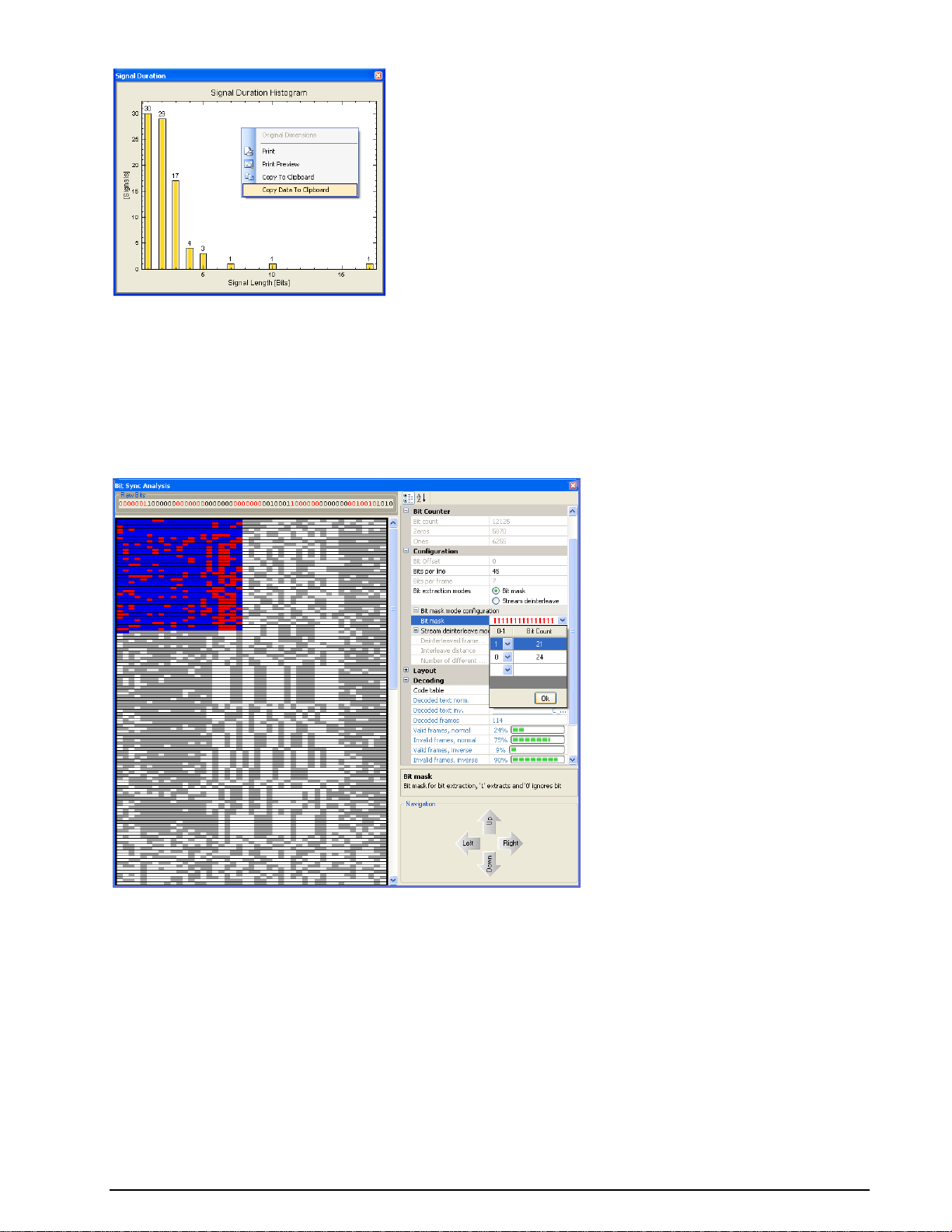
If the view has been changed by drag and drop, the original dimensions can be restored by clicking
Original Dimensions.
Bit Sync Analysis
In: Bit stream
Out: Analysis window
Function:
Opens a bit synchronization analysis window.
Bit Sync Analysis is designed to find the starting position of a frame. For this reason, all bits are
displayed in a graphical view with an adjustable number of bits per line; this makes it easier to find
periodic sequences.
The settings for Bit Sync Analysis are defined in the Properties window:
Bits per line define the number of bits per line.
Bit extraction mode offers a choice between Bit mask and Stream de-interleave modes. Depending
on the mode selected, either the bit mask or the de-interleaving can be configured. For details of these
functions, please refer to the descriptions of the Extraction and De-Interleaving Bit Stream functions
in the Bit Manipulation section of this manual.
The Layout category controls the appearance of the graphical bit display.
In the Decoding category, the decoding alphabet is selected. Supported alphabets are ITA2, ITA3,
CCIR476_5, ASCII (7 Bit) and ASCII (8 Bit). Decoding is only possible if Bit mask is activated.
BitView Manual V2.5.00 WAVECOM W-BV Function Library 57
Page 64

The CCIR476_5 and ITA3 alphabets are redundant alphabets allowing a calculation of the number of valid
frames, which is displayed in the Decoding category. This is an additional help to find the start of a frame
inside a bit stream. For the other alphabets, a validation is not possible.
The Navigation category defines the behavior of the four arrow buttons in the bottom area of the dialog
window.
Example:
Open the SITOR example analysis, located in the BitViewTool\Examples folder and select the Import
IAS Bit stream function in the History Explorer. Open the Analysis Tools in the Toolbox and select
Bit Sync Analysis. The dialog below will appear:
SITOR-A has a block length of 45, so adjust Bits per line to 45 bits. As the alphabet is known, select
CCIR476_5. The next step is to configure the Bit mask with 21 ones and 24 zeros. After configuration of
the bit mask, the dialog looks like this:
As the SITOR alphabet allows validation, the remaining task is to move the selection across the window
with the navigation arrow buttons and check the percentage of valid frames. The figure below shows a
valid bit block:
58 Function Library BitView Manual V2.5.00 WAVECOM W-BV
Page 65

The decoded text is displayed in the Decoding category.
Analysis Set Library
Familiarize yourself with Bit Analysis
To familiarize yourself with bit analysis using the rich function and tool set of BitView, it is strongly
recommended to study the working of ready-made Analysis Sets. The huge library of analysis sets is
found here,
Windows XP and earlier:
Documents and Settings\All Users\Documents \WAVECOM\BitViewTool\Examples
Documents and Settings\All Users\Shared Documents \WAVECOM\BitViewTool\Examples
Windows Windows 7:
Users\Public\Public Documents\WAVECOM\BitViewTool\Examples
Custom Library
Custom Functions
In addition to enable the user to expand the BitView toolbox with custom functions, BitView also offers a
number of read-made custom functions. These functions were originally developed as tools for internal
use, but have been made available for public use because of their general versatility. These functions have
been thoroughly tested and may serve as inspiration for users whishing to develop custom functions
BitView Manual V2.5.00 WAVECOM W-BV Analysis Set Library 59
Page 66

1200 bps (BPSK)
Bit
Symbol
0
0,1,7,6
1
4,3,5,2
2400 bps (QPSK)
Dibit
Symbol
00
0,1
01
2,3
10
6,7
11
4,5
3600 bps (8PSK)
Tribit
Symbol
000
1
001
0
010 2 011
3
100
6
101 7 110
5
111
4
themselves as they are delivered with all necessary source and project files. For more details refer to the
paragraph below, “Want to Roll Your Own functions?”.
Symbol Transcoding
In: STANAG-4285 8PSK symbols (3 bits/symbol)
Out: Transcoded STANAG-4285 bit stream
Function:
Maps a STANAG-4285 8PSK, i.e., 3 bits/symbol, bit stream to the appropriate bit(s) according to the data
rate dependent STANAG-4285 transcoding tables. Use Data rate for transcoding to select the
appropriate data rate and Symbol endianness to select Little or Big endian representation. The
following tables give the mapping between STANAG-4285 8PSK symbols and the corresponding bit
sequences for each data rate:
STANAG-4285 Deinterleaver
In: Descrambled STANAG-4285 bit stream
Out: De-interleaved STANAG-4285 bit stream
60 Custom Library BitView Manual V2.5.00 WAVECOM W-BV
Page 67

Interleaver delay [s]
Data rate [bps]
Long (10.24)
2400
1200
75 - 600
Short (0.853)
2400
1200
75 - 600
User data rate [bps]
Action
2400
Depuncture for Rate = 2/3, i.e., insert an
erasure (‘0’) after 3 bits
Function:
De-interleaves a descrambled STANAG-4285 bit stream.
The setting of Deinterleaver Mode depends on the data rate and interleaver delay of the received
STANAG-4285 bit stream.
STANAG-4285 Descrambler
In: Formatted STANAG-4285 data frame containing 8PSK symbols (3 bits/symbol)
Out: Descrambled STANAG-4285 bit stream
Function:
Descrambles a STANAG-4285 8PSK data frame encoded in big endian format. The frame must contain 176
3-bit symbols. This function does not contain any user settings.
Stream setup for Viterbi
In: Descrambled and de-interleaved STANAG-4285 bit stream
Out: Modified STANAG-4285 bit stream ready for Viterbi soft decision decoding
Function:
Modifies a descrambled and de-interleaved STANAG bit stream according to user data rate and readies it
for soft decision Viterbi decoding. Processing involves inserting three probability bits for soft decision
decoding, removing superfluous dibits for user data rates lower than 1200 bps and inserting erasures in
case of punctured codes.
Use User data rate to select the appropriate user data rate.
The table below lists the action taken by this function for each user data rate:
BitView Manual V2.5.00 WAVECOM W-BV Custom Library 61
Page 68

User data rate [bps]
Action
1200
No action
600
No action
300
Remove every second dibit
150
Remove 3 of 4 dibits
75
Remove 7 of 8 dibits
Simulate STANAG-4285
In: Text file, parameters
Out: STANAG-4285 8PSK symbol stream (3 bits/symbol)
Function:
This reference function generates all steps of a STANAG-4285 bit stream from a text message according to
the selected Deinterleaver mode and User data rate. The generated stream is then completely
decoded and thus a complete simulation of STANAG-4285 is performed.
Want to Roll Your Own functions?
The ability to expand BitViewTool with custom developed functions is one of the most powerful features of
this application. However, before you start rolling your own functions you must have a good grasp of C#,
object oriented programming and the use of Microsoft Visual Studio and .NET. In addition a solid
knowledge of MatLab and the mathematical aspects of communication systems is a prerequisite to benefit
from these powerful tools. The books listed below may help the programmer to get acquainted with the
development tools,
Bernhard Sklar, “Digital Communications: Fundamentals and Applications”, 2nd Ed., Prentice-Hall,
2001
John Sharp, “Microsoft Visual C# 2005 – Step by Step”, Microsoft Press, 2006
Ruda Pratap, “Getting Started with MATLAB 7”, Oxford
The Custom Library Interface supports the integration of third party functions into BitViewTool. Functions
may be implemented using C#.NET, using the .NET Framework 2.0. Custom functions are compiled into
individual 32-bit .NET DLLs and executed on operating systems supported by BitViewTool, including
Windows 2000, XP, 2003 Server and Windows 7 32 bit and 64 bit..
As from release 2.1 it is also possible to write mathematical functions in MatLab and integrate them with
BitViewTool.
Examples using custom functions are distributed with BitViewTool. The custom library DLL as well as the
source code can be found in the CustomLib folder of the BitViewTool. The projects (solutions) provided
were created using MS Visual Studio .NET 2010 with .NET Framework 2.0.
The CustomLib folder and a number of subfolders are created during installation.
On Windows XP and older:
62 Custom Library BitView Manual V2.5.00 WAVECOM W-BV
Page 69

On Windows 7:
The five more important ones are:
CustomLibFunction
A .NET custom library example. The output of this project is CustomLibFunction.dll, which can be used
with BitViewTool.
BVSimulateStanag4285
This project is real-life custom function used for simulation of STANAG-4285. It provides a wealth of
information for the developer. Use it as a source of inspiration when developing other custom functions.
BVCustLibMatlab
Example project for a wrapper for a MatLab custom function. The output of this project is
BVCustLibMatlab.dll.
MatlabFunctionExample
Example project for MatLab. This is an example that shows how to compile MatLab code into .NET code.
The output of this project is MatlabFunction.dll and MatlabFunction.ctf. Together with
BVCustLibMatlab.dll, these files build a MatLab custom function that can be used with BitViewTool.
BitView Manual V2.5.00 WAVECOM W-BV Custom Library 63
Page 70

VisualStudio Templates
Templates for Microsoft Visual Studio are provided to create new custom function projects. Please read the
Readme.txt file that is included in this subfolder for more information.
Adding a Custom Function
Adding a new custom function is simply done by adding its DLL to the CustomLib folder.
Windows XP and older:
Documents and Settings\All Users\Documents\WAVECOM\BitViewTool\CustomLib
Documents and Settings\All Users\Shared Documents\WAVECOM\BitViewTool\CustomLib
Windows 7:
Users\Public\Public Documents\WAVECOM\BitViewTool\ CustomLib
BitViewTool automatically adds the function to the Custom Library list in the Toolbox after launch.
Alternatively, if BitViewTool is already running, the custom function may be added to the list using the
Import Custom Library item in the Tools menu.
Please be aware that the Custom Library button will not appear in the Toolbox if a custom function is not
provided.
The icon file for the custom function is named CustomLibFunction.bmp and can be customized using the
built-in editor in Visual Studio. By compiling the custom function, the icon is integrated into the custom lib
DLL.
Use MatLab dotnetbuilders with option "Embed CTF archive into the Application". As a result, the
administrator rights for BitView are no longer required.
Constraints
All BitViewTool functions belong to one of three groups:
Source functions, which have no input.
Sink functions, which have no output.
General functions, which have both input and output, and where the input type is BitArray and the
output type may be BitArray or string.
Presently custom functions are limited to be general functions with the input and output type is BitArray.
64 Custom Library BitView Manual V2.5.00 WAVECOM W-BV
Page 71

Important Notes
When creating custom functions, certain rules must be observed. Please refer to the source code
templates and examples for more details.
The following source code elements (names) are mandatory and may not be modified:
namespace CustomLib
public string FunctionName
public string Comment
public BitArray Calculate(BitArray buf)
Property categories and additional properties may be defined without limitations.
Steps to Write a Custom Function in C# .NET
Open the CustomLibFunction example or create a new project based on the BVCustLibFunc
template
Change assembly and class name according to your needs
Modify the properties and expand the calculate function with your code
Compile the project and copy the output DLL to the CustomLib folder (see above)
Steps to Write a Custom Function with MatLab
Open the MatlabFunctionExample project (MatlabFunction.prj) in MatLab
Change the .M-File according to your needs
Compile the MatLab code. If the compilation process was successful, there will be two new files in
the .\MatlabFunction\distrib subfolder, MatlabFuntion.dll and MatlabFunction.ctf
Open the BVCustLibMatlab example or create a new project based on the BVCustLibMatlab
template
Change assembly and class name according to your needs
Set a reference to the MatlabFunction.dll in the \distrib subfolder. Thus, the BVCustLibMatlab class
will know where to find the MatLab DLL
Compile the BVCustLibMatlab project and copy all the files in the output directory to the
CustomLib folder
Place the .ctf file into the application folder (no administrator rights required for the BitView Tool).
BitView Manual V2.5.00 WAVECOM W-BV Custom Library 65
Page 72

Source Code Template / Example (C# .NET)
CustomLibFunction.cs
//--------------------------------------------------------------------------// File : CustomLibFunction.cs
// Author : WAVECOM Elektronik AG
// Date : February 2008
// Description : Template/example for a custom defined library function.
//
// Important note:
// In the project settings the "Assembly Name" must be
// equal to the "Default Namespace".
//
//---------------------------------------------------------------------------
#region using references
using System;
using System.Collections;
using System.Text;
using System.ComponentModel;
using CustomLibFunction.Properties;
#endregion
namespace CustomLib // Mandatory! Do not change this name.
{
/// <summary>
/// </summary>
[Serializable]
[DefaultProperty("FunctionName")] // adjust string if necessary, it points to a property
below
public class CustomLibFunction
{
#region Constant fields
private class PropertyCategory
{
// these are the categories in the BitViewTool property grid (Parameter Window)
public const string Information = "Information";
public const string Counter = "Counter";
public const string Configuration = "Configuration";
public const string Calculation = "Calculation";
// do not change these names, they are used to distinguish the different
categories
// when any change in the parameters happens
}
private const int MAX_SIZE = 500000; // do not modify this value
#endregion
#region Fields
// generate a new BitArray for calculation, it will be returned to the calling
function
private BitArray outbox = new BitArray(MAX_SIZE);
#endregion
#region Mandatory Properties
private string functionName = "CustomLibFunction";
/// <summary>
/// Mandatory! Do not delete this property! The string "CustomLibFunction" may be
modified.
/// This will be the name of the Function in the BitViewTool History explorer and
ToolBox
/// </summary>
[Category(PropertyCategory.Information)]
[Description("Description of CustomLibFunction goes here.\n" +
66 Custom Library BitView Manual V2.5.00 WAVECOM W-BV
Page 73

"Here: example of a custom defined library function. Inverts all the
input bits.\n")]
[DisplayName("Function Name")]
public string FunctionName
{
get
{
return (functionName);
}
}
private string comment = string.Empty;
/// <summary>
/// Mandatory! Do not modify this property!
/// </summary>
[Category(PropertyCategory.Information)]
[Description("My comments.")]
[DefaultValue("")]
public string Comment
{
get
{
return comment;
}
set
{
comment = value;
}
}
private static System.Drawing.Image iconImage = Resources.CustomLibFunction;
/// <summary>
/// If available, you can specify a custom image displayed on the function button
/// in the BitView toolbox. The image must be 16x16 pixel. The bitmap file must be
/// imported into the CustomLibFunction resources, so that it can be refered to it as
shown above!
/// Currently the image is the .bmp file 'CustomFunction.bmp'. It is part of this
solution, it can be
/// seen in the Solution Explorer Window and it can be modified.
/// If there is no image available, remove all private and public fields, i.e.
iconImage and IconImage,
/// iconTransparentColor and IconTransparentColor
/// below. A default icon image is then added by the BitViewTool main application.
/// </summary>
[Category(PropertyCategory.Information)]
[Description("Icon bitmap for Toolbox Button and History Explorer")]
[Browsable(false)]
public static System.Drawing.Image IconImage
{
get
{
return iconImage;
}
}
private static System.Drawing.Color iconTransparentColor =
System.Drawing.Color.White;
/// <summary>
/// If available, you can specify a custom image display on the function button
/// in the toolbox. The image must be 16x16 pixel, the transparent color must
/// be specified here
/// </summary>
[Category(PropertyCategory.Information)]
[Description("Icon bitmap transparent color")]
[Browsable(false)]
public static System.Drawing.Color IconTransparentColor
{
get
{
return iconTransparentColor;
}
}
#endregion
#region Optional Properties
BitView Manual V2.5.00 WAVECOM W-BV Custom Library 67
Page 74

private string dummyCalculation = string.Empty;
/// <summary>
/// Optional result form this function! DummyCalculation. Put all results into this
category
/// </summary>
[Category(PropertyCategory.Calculation)]
[Description("Description of DummyCalculation goes here. Here: number of output
bits.")]
[DisplayName("Dummy Calc.")]
public string DummyCalculation
{
get
{
return (dummyCalculation);
}
}
// add more Calculation properties here
// ...
private int dummyParameter = 0;
/// <summary>
/// Optional! Dummy Parameter. Put all input parameters for the calculation into this
category
/// </summary>
[Category(PropertyCategory.Configuration)]
[Description("Description of DummyParameter goes here. Here: not used.")]
[DefaultValue(0)]
[DisplayName("Dummy Parameter")]
public int DummyParameter
{
get
{
return (dummyParameter);
}
set
{
dummyParameter = value;
}
}
// add more Configuration properties here
// ...
#endregion
#region Constructor
/// <summary>
/// Constructor
/// </summary>
public CustomLibFunction()
{
// add initialisation code if necessary
}
#endregion
#region calculation function
/// <summary>
/// // THE calculate function. Do not change name or parameter! This function will be
searched for
/// by reflection and called for execution, when this library is added to an
analysis.
/// </summary>
public BitArray Calculate(BitArray buf)
{
if (buf == null)
return (null);
if (buf.Count <= 0)
{
outbox.Length = 0;
return (outbox);
68 Custom Library BitView Manual V2.5.00 WAVECOM W-BV
Page 75

}
//-------------------------------------------------------------------- // any calculation goes here
//---------------------------------------------------------------------
outbox = (BitArray)buf.Clone();
outbox.Not();
this.dummyCalculation = outbox.Count.ToString(); // any calculation results of
interest will be reflected in the property grid
return (outbox); // must return the result
}
#endregion
}
}
Source Code Template / Example (C# .NET for MatLab)
BVCustLibMatlab.cs
//--------------------------------------------------------------------------// File : BVCustLibMatlab.cs
// Author : WAVECOM Elektronik AG
// Date : February 2008
// Description : Template/example for a custom defined library function.
//
// Important note:
// In the project settings the "Assembly Name" must be
// equal to the "Default Namespace".
//
//---------------------------------------------------------------------------
#region using references
using System;
using System.Windows.Forms;
using System.Collections;
using System.Text;
using System.ComponentModel;
using System.Diagnostics;
using BVCustLibMatlab.Properties;
// if working with MatLab .net DLLs
using MathWorks.MATLAB.NET.Utility;
using MathWorks.MATLAB.NET.Arrays;
// reference to the MatLab dll
using MatlabFunction;
#endregion
namespace CustomLib // Mandatory! Do not change this name.
{
/// <summary>
/// </summary>
[Serializable]
[DefaultProperty("FunctionName")] // adjust string if necessary, it points to a property
below
public class BVCustLibMatlab
{
#region Constant fields
private class PropertyCategory
{
// these are the categories in the BitViewTool property grid (Parameter Window)
public const string Information = "Information";
public const string Counter = "Counter";
public const string Configuration = "Configuration";
public const string Calculation = "Calculation";
BitView Manual V2.5.00 WAVECOM W-BV Custom Library 69
Page 76

// do not change these names, they are used to distinguish the different
categories
// when any change in the parameters happens
}
private const int MAX_SIZE = 500000; // do not modify this value, it specifies
maximum number of bits processed by BitViewTool
#endregion
#region Fields
// generate a new BitArray for calculation, it will be returned to the calling
function
private BitArray outbox = new BitArray(MAX_SIZE);
#endregion
#region Mandatory Properties
private string functionName = "Test CustomLib MatLab";
/// <summary>
/// Mandatory! Do not delete this property! The string "BVCustLibMatlab" may be
modified.
/// This will be the name of the Function in the BitViewTool History explorer and
ToolBox
/// </summary>
[Category(PropertyCategory.Information)]
[Description("Description of Test CustomLib MatLab goes here.\n" +
"Here: example of a custom defined library function. Inverts all the
input bits.\n" +
"Inversion is performed by a MatLab function encapsulated in a .net
dll assembly.")]
[DisplayName("Function Name")]
public string FunctionName
{
get
{
return (functionName);
}
}
private string comment = string.Empty;
/// <summary>
/// Mandatory! Do not modify this property!
/// </summary>
[Category(PropertyCategory.Information)]
[Description("My comments.")]
[DefaultValue("")]
public string Comment
{
get
{
return comment;
}
set
{
comment = value;
}
}
private static System.Drawing.Image iconImage = Resources.matlab;
/// <summary>
/// If available, you can specify a custom image displayed on the function button
/// in the BitView toolbox. The image must be 16x16 pixel. The bitmap file must be
/// imported into the CustomLibFunction resources, so that it can be refered to it as
shown above!
/// Currently the image is the .bmp file 'CustomFunction.bmp'. It is part of this
solution, it can be
/// seen in the Solution Explorer Window and it can be modified.
/// If there is no image available, remove all private and public fields, i.e.
iconImage and IconImage,
/// iconTransparentColor and IconTransparentColor
/// below. A default icon image is then added by the BitViewTool main application.
/// </summary>
[Category(PropertyCategory.Information)]
70 Custom Library BitView Manual V2.5.00 WAVECOM W-BV
Page 77

[Description("Icon bitmap for Toolbox Button and History Explorer")]
[Browsable(false)]
public static System.Drawing.Image IconImage
{
get
{
return iconImage;
}
}
private static System.Drawing.Color iconTransparentColor =
System.Drawing.Color.FromArgb(224, 223, 227);
/// <summary>
/// If available, you can specify a custom image display on the function button
/// in the toolbox. The image must be 16x16 pixel, the transparent color must
/// be specified here
/// </summary>
[Category(PropertyCategory.Information)]
[Description("Icon bitmap transparent color")]
[Browsable(false)]
public static System.Drawing.Color IconTransparentColor
{
get
{
return iconTransparentColor;
}
}
#endregion
#region Optional Properties
// Input Parameter for calculation function
private int inpar1 = 13; // set a reasonable default value
/// <summary>
/// optional parameter for calculation, put this into the Configuration category
/// </summary>
[Category(PropertyCategory.Configuration)]
[Description("Description of Input 1 goes here")]
[DefaultValue(13)] // set a reasonable default value
[DisplayName("Input 1")]
public int Inpar1
{
get
{
return inpar1;
}
set
{
inpar1 = value;
}
}
private int inpar2 = 5; // set a reasonable default value
/// <summary>
/// optional parameter for calculation, put this into the Configuration category
/// </summary>
[Category(PropertyCategory.Configuration)]
[Description("Description of Input 2 goes here")]
[DefaultValue(5)] // set a reasonable default value
[DisplayName("Input 2")]
public int Inpar2
{
get
{
return inpar2;
}
set
{
inpar2 = value;
}
}
// add more Configuration properties here
BitView Manual V2.5.00 WAVECOM W-BV Custom Library 71
Page 78

// ...
// results from calculation function
private int outpar1 = 0;
/// <summary>
/// Optional result form this function! Put all results into the calculation category
/// </summary>
[Category(PropertyCategory.Calculation)]
[Description("Description of Output 1 goes here.")]
[DisplayName("Output 1")]
public int Outpar1
{
get
{
return outpar1;
}
}
private int outpar2 = 0;
/// <summary>
/// Optional result form this function! Put all results into the calculation category
/// </summary>
[Category(PropertyCategory.Calculation)]
[Description("Description of Output 2 goes here.")]
[DisplayName("Output 2")]
public int Outpar2
{
get
{
return outpar2;
}
}
private int outpar3 = 0;
/// <summary>
/// Optional result form this function! Put all results into the calculation category
/// </summary>
[Category(PropertyCategory.Calculation)]
[Description("Description of Output 3 goes here.")]
[DisplayName("Output 3")]
public int Outpar3
{
get
{
return outpar3;
}
}
private int outpar4 = 0;
/// <summary>
/// Optional result form this function! Put all results into the calculation category
/// </summary>
[Category(PropertyCategory.Calculation)]
[Description("Description of Output 4 goes here.")]
[DisplayName("Output 4")]
public int Outpar4
{
get
{
return outpar4;
}
}
private string outpar5 = string.Empty;
/// <summary>
/// Optional result form this function! Put all results into this category
/// </summary>
[Category(PropertyCategory.Calculation)]
[Description("Description of Output 5 (string) goes here.")]
[DisplayName("Output 5")]
public string Outpar5
{
72 Custom Library BitView Manual V2.5.00 WAVECOM W-BV
Page 79

get
{
return (outpar5);
}
}
// add more Calculation properties here
// ...
#endregion
#region Constructor
/// <summary>
/// Constructor
/// </summary>
public BVCustLibMatlab()
{
// add initialisation code if necessary
}
#endregion
#region calculation function
/// <summary>
/// // THE calculate function. Do not change name or parameter! This function will be
searched for
/// by reflection and called for execution, when this library is added to an
analysis.
/// </summary>
public BitArray Calculate(BitArray buf)
{
if (buf == null)
return (null);
if (buf.Count <= 0)
{
outbox.Length = 0;
return (outbox);
}
//-------------------------------------------------------------------- // any calculation goes here
//---------------------------------------------------------------------
try // catch any exception from matlab dll. If calling the matlab function
fails, we do not crash the app
{
// Generate data arrays for MatLab function.
// Data input for matlab function is derived from buf, which is type of
BitArray
// MatLab has not a compatible data type, so we have to convert BitArray buf
// into the MatLab default numeric type double 0.0 and 1.0
// new instance of a MatLab numeric array with a size of [buf.Length,1]
MWNumericArray data = new MWNumericArray(MWArrayComplexity.Real,
MWNumericType.Double, new int[] { buf.Length, 1 });
// Initialize data from BitArray buf
// MatLab index range is from 1...n, in C# it is from 0 ... (n-1)
for (int idx = 1; idx <= buf.Length; idx++)
{
data[idx, 1] = buf[idx - 1] ? 1.0 : 0.0;
}
// data output from matlab function is an Array of arguments
MWArray[] argsOut = null;
// prepare for calling the MatLab function, create an instance of the MatLab
function class
// generated by the MatLab deploytool, use Intellisense in visual studio,
then you see
// the list of classes found up to now in this project. Our example is
// MatLab function called 'MatlabFunction' in the .m File with the same name.
// Here is the complete listing of the MatLab .m File:
/*---------------------------------------------------------------------------
--------------------
BitView Manual V2.5.00 WAVECOM W-BV Custom Library 73
Page 80

function [y, outpar1, outpar2, outpar3, outpar4, outpar5] = MatlabFunction(
x, inpar1, inpar2 )
%
%------------------------------------------------------------------------- % Example of a function to be called from .Net environment, especially from
% a BitViewTool CustomLib function. This function declares different input
% and output parameters, to demonstrate how to access these parameters from
% a .Net environment.
%
% Inputs:
% ------ %
% x : should be a [n,1] input array containing the bit stream from the
% BitViewTool, the expected values must be 0 and 1
% inpar1, inpar2: these are parameters to control the function's behaviour
%
% Outputs:
% ------- %
% y : should be a [k,1] output array containing the bit stream as an
% output from this function, the type of y should be double or
logical.
% The values must be 0.0 and 1.0 if double.
% outpar1, outpar2, outpar3, outpat4, outpar5 : these are additional
calculation
% results from this function of type scalar or string depending on the
% function's behaviour. outpar5 is of type char array
%
%
%------------------------------------------------------------------------- % After this function is debugged and tested, the MatLab deploytool has to be
% started with 'deploytool' in the Command Window
% In the deploytool create a new .net project, project type is .NET
% Component, enter a Component name, in the project settings under .NET set
the
% the Microsoft Framework to Version 2.0, the Assembly type to private.
% Then push the Build Project button in the Deployment toolbar.
% When finished copy the .dll and .ctf files from the function's
% project\distrib directory to the BitViewTool customlib directory
% C:\Documents and Settings\All Users\Documents\WAVECOM\BitViewTool\CustomLib
%
% Next step is to create a new WAVECOM CustomLib function from the template
% found in the new project wizzard in Visual Studio.
% Add a the reference in the Solution Explorer to the .dll just copied to to
% CustomLib directory. Add a reference in the C# CustomLib source under the
% 'using' region, the namespace to be used is the same used in the solution
% explorer.
%
%--------------------------------------------------------------------------
outpar1 = nargin; % for example : outpar1 returns number of input function
arguments
[m, n] = size( x ); % for example : outpar2 returns length of input array
x, i.e. number of rows
outpar2 = m;
outpar3 = n; % number of columns, should be 1 in our example
outpar4 = inpar1 * inpar2; % example of calculation for outpar4
y = ~x; % this is the only calculation for the input data, outpt
y is inverse(x)
% and converts y to type 'logical' !!!!
if (n ~= 1)
outpar5 = 'Function error: input data dimension [m,n] with n ~= 1';
else
outpar5 = 'Function called successfully';
end
-----------------------------------------------------------------------------
------- */
// we can now see 3 Input parameters and 6 output parameters
// x is the input data column vector, type is double
// y is the returned column vector, type can be double or logical,
// all other parameters are scalars, expected
74 Custom Library BitView Manual V2.5.00 WAVECOM W-BV
Page 81

// to be of type double, outpar5 is of type string
// Use Intellisense to see all available classes
// the matlab deploytool generates a class by using the MatLab function name
// with 'class' appended:
MatlabFunctionclass MatlabFunc = new MatlabFunctionclass(); // new instance
of MatLab function
// now call this function, with 6 output parameters : y and outpar 1...5
argsOut = MatlabFunc.MatlabFunction(6, data, (double)Inpar1, (double)Inpar2);
// now get all results from argsOut, its an array of numeric/char arrays
// the first entry is our bit array result, can be of type numeric(double) or
logical,
// depending on the matlab function internal code
if ((argsOut[0].IsNumericArray) && (argsOut[0].NumberofDimensions == 2))
// if numeric and number of dimension exactly 2
{
MWNumericArray numericBits = (MWNumericArray)argsOut[0]; // cast to
MWNumericArray
MWNumericType numericType = numericBits.NumericType; // get the
numeric type, can be double, float, int, etc..., this has to be checked
Array numericBitsArray = numericBits.ToVector(MWArrayComponent.Real);
// must be anything but not complex !!!
int length;
switch (numericType) // check types, we expect double
{
case MWNumericType.Double:
double[] doubleArray = (double[])numericBitsArray; // cast to
double array
length = doubleArray.Length;
if (length > MAX_SIZE)
{
length = MAX_SIZE;
}
// convert now result to type of BitArray
for (int i = 0; i < length; ++i)
{
outbox[i] = (doubleArray[i] == 0.0) ? false : true;
}
outbox.Length = length; // set length explicitely, otherwise we
have MAX_SIZE !!
break;
case MWNumericType.Int32:
Int32[] int32Array = (Int32[])numericBitsArray; // cast to int32
array
length = int32Array.Length;
if (length > MAX_SIZE)
{
length = MAX_SIZE;
}
// convert now result to type of BitArray
for (int i = 0; i < length; ++i)
{
outbox[i] = (int32Array[i] == 0) ? false : true;
}
outbox.Length = length; // set length explicitely, otherwise we
have MAX_SIZE !!
break;
case MWNumericType.Int16:
Int16[] int16Array = (Int16[])numericBitsArray; // cast to int16
array
length = int16Array.Length;
if (length > MAX_SIZE)
{
length = MAX_SIZE;
}
// convert now result to type of BitArray
for (int i = 0; i < length; ++i)
{
outbox[i] = (int16Array[i] == 0) ? false : true;
}
BitView Manual V2.5.00 WAVECOM W-BV Custom Library 75
Page 82

outbox.Length = length; // set length explicitely, otherwise we
have MAX_SIZE !!
break;
case MWNumericType.Int8:
Byte[] byteArray = (Byte[])numericBitsArray; // cast to int16
array
length = byteArray.Length;
if (length > MAX_SIZE)
{
length = MAX_SIZE;
}
// convert now result to type of BitArray
for (int i = 0; i < length; ++i)
{
outbox[i] = (byteArray[i] == 0) ? false : true;
}
outbox.Length = length; // set length explicitely, otherwise we
have MAX_SIZE !!
break;
default: // other numeric types not supported
throw new ApplicationException("Bad type returned from " +
FunctionName);
}
}
else if ((argsOut[0].IsLogicalArray) && (argsOut[0].NumberofDimensions == 2))
// if logical and number of dimension exactly 2
{
MWLogicalArray logicalBits = (MWLogicalArray)argsOut[0]; // cast
to MWLogicalArray
bool[] boolOutputArray;
boolOutputArray = logicalBits.ToVector(); // convert all to a bool
array in .net
outbox = new BitArray(boolOutputArray); // then initialize a
BitArray for use with BitViewTool
}
else
{
throw new ApplicationException("Bad type returned from " + FunctionName);
}
// now get other results, we do not check types again, but you should do that
outpar1 = (int)(MWNumericArray)argsOut[1];
outpar2 = (int)(MWNumericArray)argsOut[2];
outpar3 = (int)(MWNumericArray)argsOut[3];
outpar4 = (int)(MWNumericArray)argsOut[4];
outpar5 = ((MWCharArray)argsOut[5]).ToString();
}
catch (Exception ex)
{
MessageBox.Show(ex.Message.ToString(), "Errors in " + FunctionName);
outbox.Length = 0;
}
return (outbox);
}
#endregion
}
}
Source Code Template / Example (MatLab)
MatlabFunction.m
function [y, outpar1, outpar2, outpar3, outpar4, outpar5] = MatlabFunction( x, inpar1, inpar2
)
%
%-------------------------------------------------------------------------% Example of a function to be called from .Net environment, especially from
76 Custom Library BitView Manual V2.5.00 WAVECOM W-BV
Page 83

% a BitViewTool CustomLib function. This function declares different input
% and output parameters, to demonstrate how to access these parameters from
% a .Net environment.
%
% Inputs:
% ------%
% x : should be a [n,1] input array containing the bit stream from the
% BitViewTool, the expected values must be 0 and 1
% inpar1, inpar2: these are parameters to control the function's behaviour
%
% Outputs:
% -------%
% y : should be a [k,1] output array containing the bit stream as an
% output from this function, the type of y should be double or logical.
% The values must be 0.0 and 1.0 if double.
% outpar1, outpar2, outpar3, outpat4, outpar5 : these are additional calculation
% results from this function of type scalar or string depending on the
% function's behaviour. outpar5 is of type char array
%
%-------------------------------------------------------------------------% After this function is debugged and tested, the MatLab deploytool has to be
% started with 'deploytool' in the Command Window
% In the deploytool create a new .net project, project type is .NET
% Component, enter a Component name, in the project settings under .NET set the
% the Microsoft Framework to Version 2.0, the Assembly type to private.
% Then push the Build Project button in the Deployment toolbar.
% When finished copy the .dll and .ctf files from the function's
% project\distrib directory to the BitViewTool customlib directory
% C:\Documents and Settings\All Users\Documents\WAVECOM\BitViewTool\CustomLib
%
% Next step is to create a new WAVECOM CustomLib function from the template
% found in the new project wizzard in Visual Studio.
% Add a the reference in the Solution Explorer to the .dll just copied to to
% CustomLib directory. Add a reference in the C# CustomLib source under the
% 'using' region, the namespace to be used is the same used in the solution
% explorer.
%
%--------------------------------------------------------------------------
outpar1 = nargin; % for example : outpar1 returns number of input function arguments
[m, n] = size( x ); % for example : outpar2 returns length of input array x, i.e. number of
rows
outpar2 = m;
outpar3 = n; % number of columns, should be 1 in our example
outpar4 = inpar1 * inpar2; % example of calculation for outpar4
y = ~x; % this is the only calculation for the input data, output y is inverse(x)
% this converts y to type 'logical' !!!!
if (n ~= 1)
outpar5 = 'Function error: input data dimension [m,n] with n ~= 1';
else
outpar5 = 'Function called successfully';
end
Appendix
License Terms
1. Wavecom decoder software and other relevant products are license protected, e.g., WIBU CodeMeter
dongle.
BitView Manual V2.5.00 WAVECOM W-BV Appendix 77
Page 84

2. The license must be legally acquired. The protected software or the product itself can only be operat-
ed simultaneously up to the amount of acquired licenses. This means that a double license allows the
user to operate the product simultaneously in two instances maximum.
3. Any manipulation of the license, e.g., the amount, validity or to circumvent the license is prohibited.
Wavecom cannot fix the occurred damages, e.g., automatic annulations of the license or physical
change of hardware component. In these cases the product must be newly acquired at its full price.
4. Any manipulation to Wavecom software, especially hacking and reverse-engineering of the product is
prohibited. The damage occurred thereby will be passed on to the user, as pointed out in article (3) of
these License Terms.
5. Any Wavecom software may not be copied without the consent of Wavecom.
Address
WAVECOM ELEKTRONIK AG
Hammerstrasse 8
CH-8180 Buelach
Switzerland
Phone: +41-44-872 70 60
Fax: +41-44-872 70 66
E-mail: info@wavecom.ch
Web: www.wavecom.ch
78 Appendix BitView Manual V2.5.00 WAVECOM W-BV
Page 85

Hardware Page
Remarks
WebAdmin
Starts the CodeMeter WebAdministrator in your Internet standard browser.
Eject
Used to safely remove (a) CmStick(s).
Change Name
Use this button to change the name of the selected CmStick.
Just click the button "Change Name" and enter the new name into the field in the
“Change Name” window.
Change Password
Use this button to change the current CmStick password.
If you should have forgotten your CmStick password, you can use your CodeMeter
Master-Password to create a new CmStick password.
Firmware Update
Use this button to update the firmware of the CmStick to the current version.
To execute the firmware update an Internet connection is required.
Do not remove your CmStick during the CodeMeter firmware update. This can cause
serious damage to the CmStick.
CodeMeter and CmStick
Important: For current and detailed information consult the CodeMeter help files.
CodeMeter Control Center
When the CodeMeter has been installed the CodeMeter Control Center may be opened by clicking the
CodeMeter icon in the Windows system tray.
The Control Center offers several configuration options via its menu bar and its three tabs in addition to
basic information regarding the installation.
The tabs cover the areas listed below
Hardware
Events
Licensing
CodeMeter Hardware
BitView Manual V2.5.00 WAVECOM W-BV Appendix 79
Page 86

Events Page
Remarks
WebAdmin
Starts the CodeMeter WebAdministrator in your Internet standard browser
Events
The Event window contains general information on:
The number of the connected CmSticks detected
The number of available CmStick entries
The number of Firm Items
All access to the CodeMeter Runtime Server
Licensing Page
Remarks
WebAdmin
Starts the CodeMeter WebAdministrator in your Internet standard browser
CmStick
Select the desired CmStick by selecting its serial number
Create Context
Use this option to create a Remote Context file for the selected CmStick
Execute Update
Use this option to write the data from a Remote Update file into the selected
CmStick. Further information can be found in the Field Activation Services (CmFAS)
page of the CodeMeter help file
File Menu
Remarks
WebAdmin
Starts the CodeMeter WebAdministrator in your Internet standard browser
Logging
Activate/deactivate the logging process. If activated CodeMeter will automatically
create a logging file in the CodeMeter installation folder (default[windows]:
[..\ProgramFiles\CodeMeter\logs])
CodeMeter Events
CodeMeter Licensing
CodeMeter File
80 Appendix BitView Manual V2.5.00 WAVECOM W-BV
Page 87

Quit
Closes the CodeMeter Control Center window without stopping the CodeMeter
Runtime Server process
Process Menu
Remarks
Eject CmSticks
Used to safely remove (a) CmStick(s)
Defragment License
Memory
Defragment the memory part in the CodeMeter Chip (affects selected
CmStick)
Update Time Certificate
Performs a Certified Time update for the selected CmStick
Start CodeMeter Service
Starts the CodeMeter Runtime Server service/daemon
Stop CodeMeter Service
Stops the CodeMeter Runtime Server service/daemon
View Menu
Remarks
Show all Connected
CmSticks
Prints a list of all connected CmSticks
Hide Window
Hides the CodeMeter Control Center
Show All Available Entries
Prints a list of all available CmStick entries
List All Open Handles
Prints a list of all currently opened and used CodeMeter handles. This information is useful for developers
Clear Event Windows
Clear all entries in the event window
Copy Event Contents
Copy the contents of the event window
Zoom In
Increases the font size of the event window content
Zoom Out
Decreases the font size of the event window content
CodeMeter Process
CodeMeter View
BitView Manual V2.5.00 WAVECOM W-BV Appendix 81
Page 88

CodeMeter WebAdmin
CodeMeter WebAdmin Home
The home page displays general information about your computer and the CodeMeter WebAdministrator.
By pressing the button with the DNS name of your PC, the server selection pop-up window will appear.
By using the drop-down menu, it is possible to select a different CodeMeter Server.
CodeMeter WebAdmin Content
The Content page is split into four subsections:
CmStick
Licenses
User Data
Backup/Restore
82 Appendix BitView Manual V2.5.00 WAVECOM W-BV
Page 89

Content CmStick
Remarks
CmStick
You can select a CmStick via the drop-down menu by choosing its serial number.
Name
Shows the name for the selected CmStick.
Hardware
Shows the hardware version of the selected CmStick.
First Device
Shows the drive letter and the size of the first CodeMeter partition, if a CmStick/M
(CmStick with flash memory) is connected.
Status
Shows the current status of the selected CmStick.
You can change the status of your CmStick by using the CodeMeter Control Center.
Certified Time
Displays the current internal Certified Time of the selected CmStick.
You can get a Certified Time update from the defined CodeMeter Time Server by
clicking on the “Update” button.
Box Time
Shows the Box Time (internal time) of your CmStick.
System Time
Displays the selected CmStick’s internal clock time.
Free Memory
Displays the selected CmStick’s available memory. To defragment the CmStick
memory, click the “Defragment” button.
The CmStick page offers different CmStick management options.
The Licenses page shows all licenses (Firm Items) contained in the selected CmStick. Beneath each Firm
Item, which is characterized by its Firm Code and "Name", a list of all corresponding Product Codes is di splayed.
To get an overview of all stored products for any Firm Item, just click on the Firm Code entry.
For detailed information about a Product Item click on the Product Code entry in the Product Item field
BitView Manual V2.5.00 WAVECOM W-BV Appendix 83
Page 90
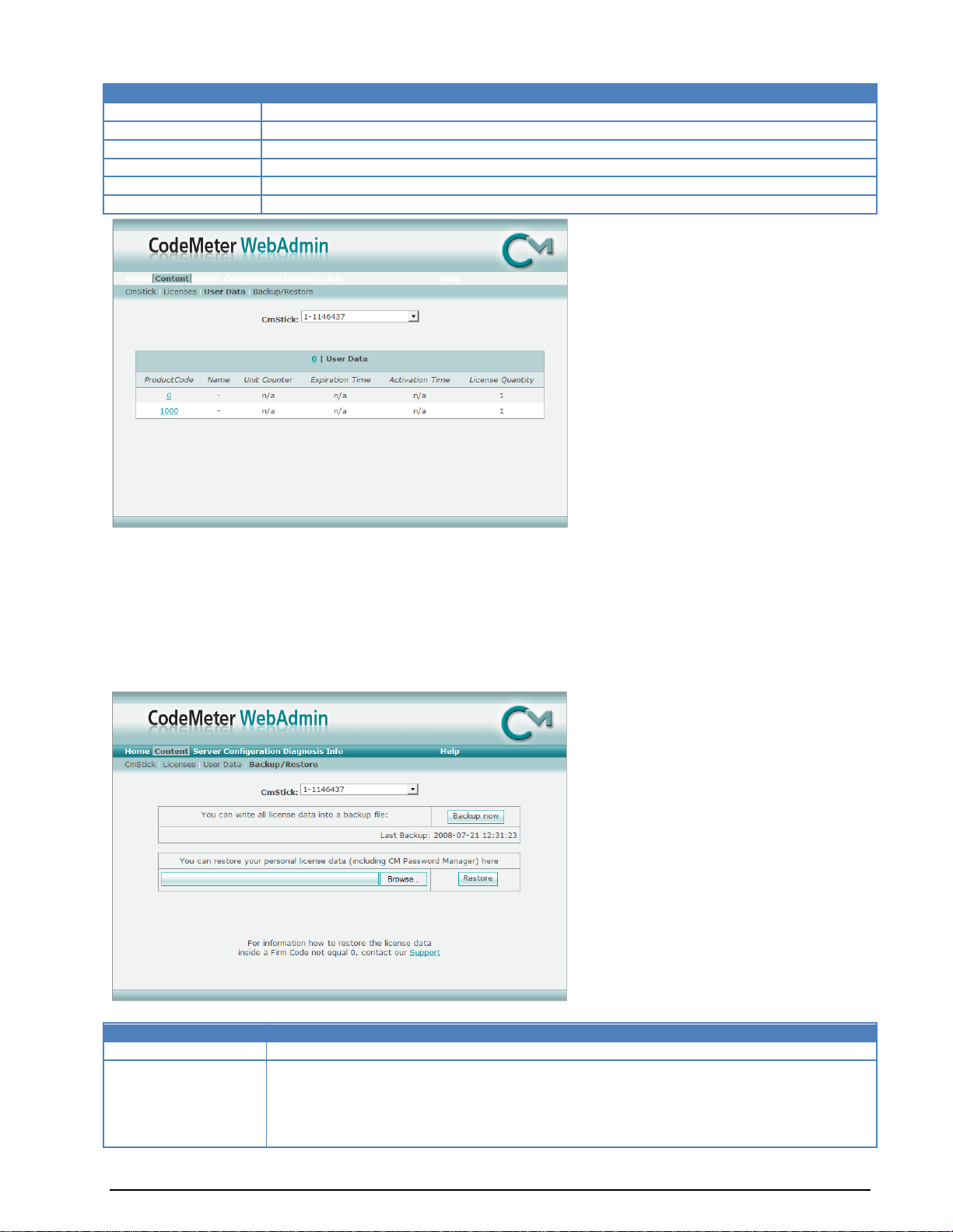
Content License
Remarks
Product Code
Shows the Product Code for the Product Item
Name
Displays the Product Item Text, normally the name of the product
Unit Counter
Displays (if available) the remaining credits for this product
Expiration Time
Displays the Expiration Time of the product, if it is available
Activation Time
Displays the Activation Time of the product, if it is available
License Quantity
Displays the number of licenses that are available for this product
Content License
Remarks
CmStick
With the CmStick drop-down box, you can select the desired CmStick.
Section Create
Backup
By clicking the "Backup now" button, you can perform a backup of all personal
CmStick User Data (User Data page). A backup file will be created in the defined
folder (see Configuration Page - Backup).
Additionally, the date and the time stamp of your last CmStick backup are displayed.
The User Data page shows detailed information about the Firm Code 0 (Implicit Firm Item).
The Implicit Firm Item or the Firm Code 0 is "The user's own Firm Code". Every time a program wants to
create a new entry into this Firm Code, CodeMeter asks for the CmStick password. CodeMeter will only
allow the program to create a new entry or to change data if the password is correctly entered.
The User Data is saved automatically and can be restored if needed.
Further information about the backup and restore functionality can be found on the Backup/Restore
page.
The table structure is the same as for the “Content License” table.
On the Backup/Restore page, you can create CmStick backups or restore saved user data (licenses).
84 Appendix BitView Manual V2.5.00 WAVECOM W-BV
Page 91

Section Restore
Backup
Use this option to restore saved personal license data from a backup file.
It is also possible to transfer this data to another CmStick. Therefore the new
CmStick must have the same password as the first CmStick.
CodeMeter WebAdmin Server
The Server page displays detailed information about all available CodeMeter network licenses. The Server
page is split into two subsections:
Cluster
User
The Cluster sub-section.
Note: Network licenses can only be used if the CodeMeter Runtime Server is started as a network server.
BitView Manual V2.5.00 WAVECOM W-BV Appendix 85
Page 92

Item
Remarks
Product Code
Displays the Product Code
Name
Displays the name of the Product Item, normally the name of the product
Feature Map
Displays the Feature Map. The Feature Map is used to control the WAVECOM software
upgrade period
Licenses
Displays the total number of network licenses
User Limit
Displays the number of licenses that are currently used in the User Limit mode
No User Limit
Displays the number of licenses that are currently used in the No User Limit mode
Exclusive
Displays the number of licenses that are currently used in the Exclusive mode
Shared
Displays the number of licenses that are currently used in the Shared mode
Free
Displays the number of licenses that are currently unused
Details
Displays detailed information about network licenses in use
Server User
Remarks
CmStick
Displays the serial number of the connected CmStick
Firm Item
Displays information about the Firm Item (Firm Code and text)
Product Code
Displays the Product Code
Client
Displays the IP address of the current CodeMeter client
Access Mode
Displays the current Access Mode
The User sub-section.
This screen displays detailed information about the network licenses in use. The upper area displays
general information about the selected network licenses.
86 Appendix BitView Manual V2.5.00 WAVECOM W-BV
Page 93

License Details
Remarks
ID
Displays the current CodeMeter process ID on the network server
Client (User)
Displays the IP address of the connected CodeMeter clients
Client Process ID
Displays the current CodeMeter process ID on the client PC
Application Information
Displays application specific information
Access Mode
Displays the current Access Mode
First Access
Displays the date and time stamp of the first access (client to server)
Last Access
Displays the date and time stamp of the last access (client to server)
Action
By clicking the "Cancel" button the selected license will be freed
License Details
Remarks
Bind Address
Select which network adapter (virtual adapter) the CodeMeter Runtime Server will be
bound to. This is very useful if your PC has several network adapters and it should act as
a network license server.
By default, the CodeMeter Runtime Server uses the first detected network adapter (NIC).
Network
Port
Port 22350 is the standard port for CodeMeter communication. You may edit this value if
required. If changing port number make sure that all CodeMeter Runtime Servers use the
same port if you want to use an application via the network.
UDP Waiting Time
Specifies the maximum UDP wait time.
This time specifies the maximum time interval within which UDP requests (requests via
the UDP protocol) must be answered.
Run Net-
If this option is enabled, the specified PC may be used as a CodeMeter Network Server.
Important: If a network license that is currently in use is canceled, the associated client application will
experience an error. Please, ensure that the selected license is not in use.
CodeMeter WebAdmin Configuration
The Configuration page is split into six sub-sections:
Network
Proxy
Access Control
Certified Time
WebAdmin
Backup
The Network sub-section.
BitView Manual V2.5.00 WAVECOM W-BV Appendix 87
Page 94

work Server
Server
Search List
On the Server Search List you can define the access to specific CodeMeter Servers. In this
case the client only searches for these servers. To do so, just set the DNS name or the IP
address of the CodeMeter Server in the Server Search List.
If the CodeMeter Server is located in a different subnet, it is strongly recommended that you use the IP address of the CodeMeter Server in the Server
Search List.
Configuration
Proxy
Remarks
Proxy support
Enable or disable Proxy Server support; this option has to be enabled if you are
using a proxy server
Proxy Server
Set the IP address of your proxy server
Proxy Port
Set the port number of your proxy server
Authentication
Enable or disable the proxy server authentication
Proxy User
User ID for the proxy server
Proxy Password
User password for the proxy server
The Proxy sub-section.
The Access Control sub-section.
88 Appendix BitView Manual V2.5.00 WAVECOM W-BV
Page 95

Configuration Access Control
Remarks
Clients
Shows a list of all CodeMeter client computers that have permission to use the
CodeMeter Server (check out a license).
If this list is empty (default setting), all CodeMeter Clients are allowed to use the
CodeMeter Server.
Add, Remove
To allow a special CodeMeter Client to use the CodeMeter Server, just click on
the “Add” button and enter the IP address or the DNS name of the client into the
input box. To remove a Client, highlight its IP address and click “Remove”.
Access FS
If this feature is enabled (box is checked), CodeMeter Clients or developer PCs
can access the CodeMeter Firm Security Box (FSB). To disable this feature, uncheck the check-box.
This feature is only useful for CodeMeter Licensors.
Configuration Certi-
fied Time
Remarks
Time Server
Specify the access order or add/remove the IP address or the URL of a
CodeMeter Time Server using the “add”, “remove”, “up” and “down” buttons
Time Out
Set the time out value of the CodeMeter Time Servers
Config. WebAdmin
Remarks
Remote Read
Check this box to allow remote reading of your CodeMeter Runtime Server over the
network
Remote Write
Check this box to allow a remote access to change the configuration settings of
The Certified Time sub-section.
The WebAdmin sub-section.
BitView Manual V2.5.00 WAVECOM W-BV Appendix 89
Page 96

your CodeMeter Runtime Server
Language
Specify the language used in your CodeMeter WebAdministrator
Config. Backup
Remarks
Backup Path
Specify the Backup Path to which the CmStick backup is written
The default Backup Path under Windows is [\CodeMeter\Runtime\bin]
Backup Interval
Specify the interval (in hours) between CodeMeter automatic backups. The default
value is 24 hours
Certified Time
Check to enable a Certified Time update before each backup
The Backup sub-section.
Note: Manual backups can be done immediately - instructions can be found on the Backup page.
CodeMeter WebAdmin Diagnosis
The Contents page is split into two sub-sections:
Logfile
CmTalk
The Logfile sub-section.
With the enabled option you can activate or deactivate the logging function.
90 Appendix BitView Manual V2.5.00 WAVECOM W-BV
Page 97

If the logging function is activated, the Logfile page displays the contents of the current log file in the
CodeMeter installation folder (default: [..\ProgramFiles\CodeMeter\Logs]).
The CmTalk sub-section.
This page provides the possibility to test the CmTalk environment.
The CmTalk protocol is required for the automatic transfer or update of CodeMeter licenses via the
Internet.
CodeMeter WebAdmin Info
General information regarding the CodeMeter system.
BitView Manual V2.5.00 WAVECOM W-BV Appendix 91
Page 98

Page 99

Glossary of Terms
ANSI
An acronym for the American National Standards Institute, an organization that sets standards for a
variety of programming languages and systems.
ASCII
An acronym for American Standard Code for Information Interchange, pronounced "ASK-ee." It is a code
in which the numbers from 0 to 127 stand for letters, numbers, punctuation marks and other characters.
ASCII code is standardized to facilitate transmitting text between computers or between a computer and a
peripheral device.
BCH
A BCH (Bose, Ray-Chaudhuri, Hocquenghem) code is an error-correcting code. It is a multilevel, cyclic,
error-correcting, variable-length digital code used to correct mutiple random error patterns.
Convolutional code
A type of channel coding that adds patterns of redundancy to the data in order to improve the signal-tonoise ratio (SNR) for more accurate decoding at the receiving end. The Viterbi algorithm is used to decode
a particular type of convolutional code
CRC
CRC (Cyclical Redundancy Checking) is an error checking technique used to ensure the accuracy of
transmitting digital data. The transmitted messages are divided into predetermined lengths which, used as
dividends, are divided by a fixed divisor. The remainder of the calculation is appended onto and sent with
the message. At the receiving end, the computer recalculates the remainder. If it does not match the
transmitted remainder, an error is detected.
DEFLATE
Deflate is a lossless data compression algorithm that uses a combination of the LZ77 algorithm and
Huffman coding.
HDLC
HDLC (High-level Data Link Control) is a group of protocols for transmitting synchronous data packets
between point-to-point nodes. In HDLC, data is organized into a frame. HDLC uses zero insertion/deletion
process (bit stuffing) to ensure that the bit pattern of the delimiter flag does not occur in the fields
between flags.
HEX
In mathematics and computer science, hexadecimal, or simply hex, is a numeral system with a radix or
base of 16 usually written using the symbols 0–9 and A–F or a–f.
BitView Manual V2.5.00 WAVECOM W-BV Glossary of Terms 93
Page 100

Huffman coding
Huffman coding is an entropy encoding algorithm used for lossless data compression. The term refers to
the use of a variable-length code table for encoding a source symbol (such as a character in a file) where
the variable-length code table has been derived in a particular way based on the estimated probability of
occurrence for each possible value of the source symbol. It was developed by David A. Huffman
LZ77
LZ77 is the name for a lossless data compression algorithms published in papers by Abraham Lempel and
Jacob Ziv. LZ77 algorithms achieve compression by replacing portions of the data with references to
matching data that has already passed through both encoder and decoder.
Matlab
MATLAB is a numerical computing environment and programming language. Created by The MathWorks,
MATLAB allows easy matrix manipulation, plotting of functions and data, implementation of algorithms,
creation of user interfaces, and interfacing with programs in other languages. Although it specializes in
numerical computing, an optional toolbox interfaces with the Maple symbolic engine, allowing it to be part
of a full computer algebra system.
Puncturing
Puncturing is a procedure whereby a code with code rate 1/2 is transformed to another code rate by
deleting some bits (“erasures”) for the encoder output bit stream. The deletion is done according to a
puncturing matrix. The erasures must be re-inserted in the received bit stream for a Viterbi decoder to
work properly.
94 Glossary of Terms BitView Manual V2.5.00 WAVECOM W-BV
 Loading...