

Page 1

User Manual
W51PC DCOM Interface
V1.1
By WAVECOM ELEKTRONIK AG
Page 2

PUBLISHED BY
WAVECOM ELEKTRONIK AG
Hammerstrasse 8
CH-8180 Buelach
Switzerland
Phone +41-44-872 70 60
Fax +41-44-872 70 66
Email: info@wavecom.ch
Internet: http://www.wavecom.ch
© by WAVECOM ELEKTRONIK AG. All rights reserved.
Reproduction in whole or in part in any form is prohibited without written
consent of the copyright owner.
The publication of information in this document does not imply freedom
from patent or other protective rights of WAVECOM ELEKTRONIK AG or
others.
All brand names in this document are trademarks or registered trademarks of their owners.
Specifications are subject to change without further notice
Printed: Wednesday, January 30, 2008, 12:51:15
Page 3

Contents
Welcome 1
Professional Version 1
Options 1
Training 1
Source Code 1
Company Profile 1
Revisions 2
Introduction 2
Remote Control Interface 4
Class W51Server 4
Iw51System 4
Iw51System Methods 5
Iw51DataSink 8
Iw51DataSink Methods 9
RawData format for FAX 10
Class W51Param 10
ICW51Param 10
ICW51Param Methods 10
List of Parameters 11
List of parameters supported by W51System class 11
Programming Examples 18
Visual FoxPro 18
Visual Basic 19
MATLAB 20
Microsoft C 20
Glossary of Terms 21
Index 25
User Manual W51PC DCOM Interface V1.1 Contents • iii
Page 4

Page 5

Welcome
Congratulations on your purchase of a WAVECOM decoder. The product
that you bought incorporates the latest technology in data decoding together with the latest software release available at the time of shipment.
Please, check our website http://www.wavecom.ch for software updates.
Always check the latest documentation on the installation CD or on our
website.
We thank you for choosing a WAVECOM decoder and look forward to
work with you in the future.
This chapter introduces WAVECOM, the field of activity of the company,
and how you may benefit from the expertise of WAVECOM.
Professional Version
This documentation is only available in the professional version of the
WAVECOM decoder software.
Professional versions are only available to government bodies.
WAVECOM maintains a mailing list of our professional customers. For
registration details, see Appendix at the end of this manual.
Options
Training
Source Code
Company Profile
Different additional options are available from WAVECOM.
In the manual, options are marked with (Option).
Options are only available to government bodies.
Please, note that when required WAVECOM is able to provide training on
the WAVECOM XML interface. Training can be ordered to take place at
the customer location or at our offices in Switzerland.
Source code is available for professional users. Please, inquire to receive
an offer from WAVECOM if you plan to add your own modes.
WAVECOM ELEKTRONIK GmbH was founded in 1985 in Hohentengen,
Germany, close to the Swiss border. In 1991 the company moved to
Switzerland and established itself as WAVECOM ELEKTRONIK AG.
Now located in Buelach it is within close vicinity of Zuerich airport.
User Manual W51PC DCOM Interface V1.1 Welcome • 1
Page 6

Revisions
The company has focused on decoding and analysis systems for wireless data transmissions. The wide product range spans from professional, high performance systems to devices for private and amateur radio
use.
The very high quality standards combined with high system performance
are appreciated by all customers worldwide. A global network of authorized sales partners ensures that local assistance and basic level support
can be provided in most places. More than 95% of all units sold are exported. The majority of the customers are government agencies, defense
organizations and the telecommunication industry.
About 40% of the turnover is invested in research and development. The
employees at WAVECOM ELEKTRONIK AG are mainly engineers wi th
experience in DSP technology, computer and RF hardware development,
software engineering and radio data transmission. Access to external
know-how and human resources enlarges the capabilities for realizing
projects. Manufacturing is outsourced to specialized companies within
Switzerland which can handle today's needs for processing surface
mount components and fine-pitch structures.
WAVECOM ELEKTRONIK AG does not have any juridical or financial
links or connections to other companies or official bodies and is completely owned by its general manager, Mr. Christian Kesselring.
Version Date Changes
1.0 28.Aug 2006 Removed from the W 51 Manual and put in a sepa-
1.1 30.Jan 2008 HRESULT GetTextData([out] BSTR *Data) ex-
Introduction
DCOM is no longer supported in future WAVECOM products. It still exists
in the W4oPC, W41PC and W51PC. Please convert your existing
W51PC software to the XML interface
The WAVECOM program consists of two parts. The first part is called the
WAVECOM Client and contains the user interface, menus, dialogs and
graphics. The second part, called the WAVECOM Server, contains the interface to the decoder card. The WAVECOM Server communicates with
the decoder card and it always run on the machine containing the DSP
card. Client applications use DCOM to connect to the WAVECOM Server
from anywhere on the network.
rate document.
tended for codes that have more than one channel.
2 • Introduction User Manual W51PC DCOM Interface V1.1
Page 7
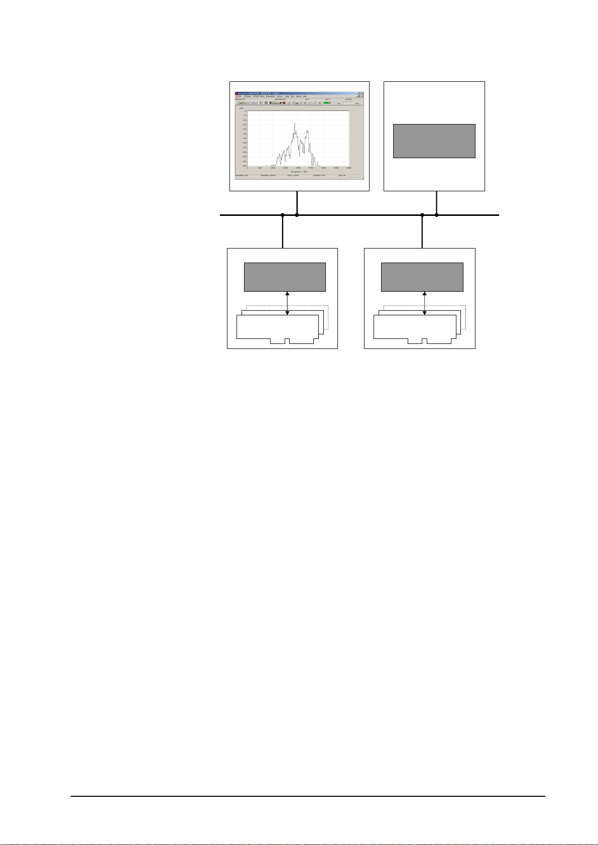
Computer
Computer
Client Application
Computer
SERVER
Wavecom Cards
Computer
SERVER
Wavecom Cards
The WAVECOM Server provides two interfaces. The first is a comprehensive interface providing all the functionality required by the
WAVECOM Client application. The second interface is a simplified interface providing only the functions required for an external application. This
interface is compatible with the OLE automation standard to allow applications written in various programming languages to interface to the
WAVECOM Server.
User Manual W51PC DCOM Interface V1.1 Introduction • 3
Page 8
Remote Control Interface
IWxxParam
1
2
3
4
4
signal output appear on
3
2
1
Client Application
IWxxSystem
Interface diagram
IWxxDataSink
WxxServer
Class
WxxPC Cards
WxxParam
Class
WxxPC
Class W51Server
W51Server is implemented as an out-of-process server. It can either be
used as a Local Server (on the same machine) or a Remote Server (on
another machine). The W51Server program supports the Iw51System interface for use by any client application.
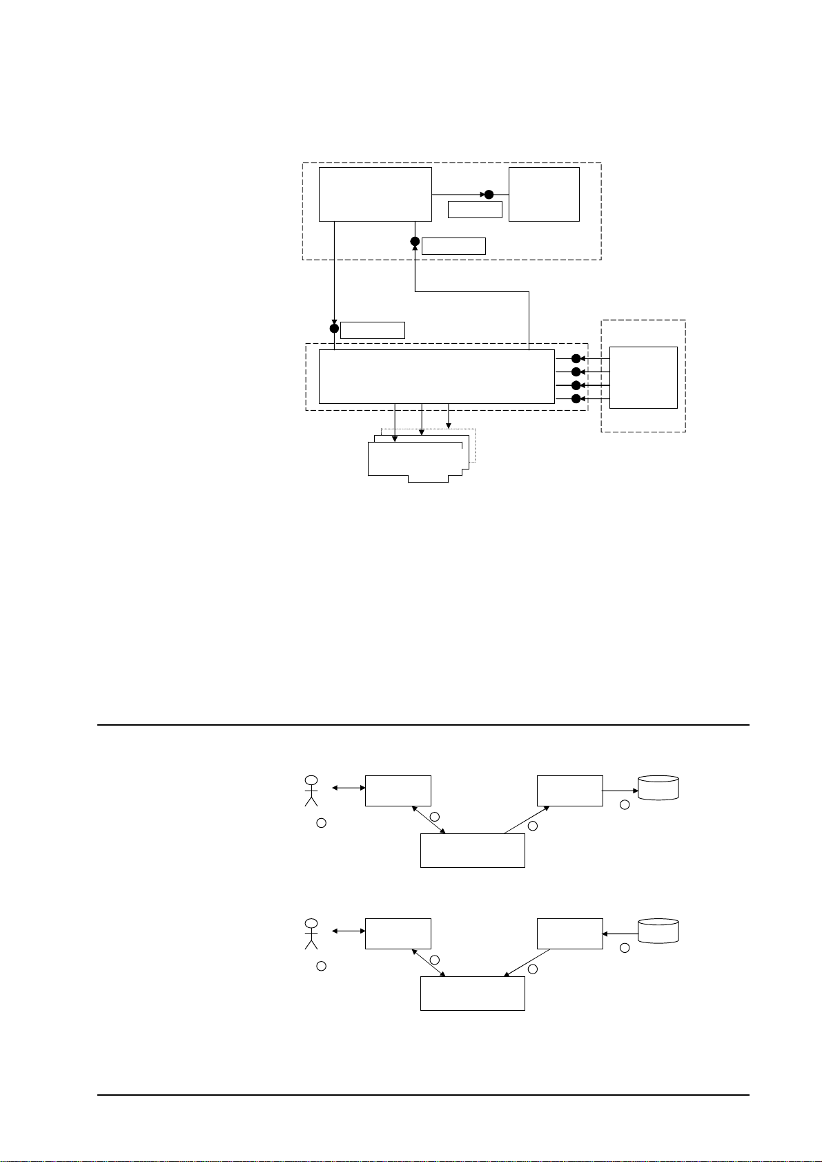
Iw51System
Decoder
User Interface
User locate and start
decoding a signal
Similarly, the client application can set the state of the decoder card.
Decoder
User Interface
User see parameters
changing. Decoded
the screen.
Card communicate
parameters to server
Wxx PC Server
Server communicate
parameters to decoder
Card
Wxx PC Server
Client
Application
Client Application
retrieve parameters
from server using
the Iwxx System
interface
Client
Application
Client Application
set parameters in
server using the
Iwxx System
interface
Client Application
save parameters in
database
Client Application
retrieve parameters
from database
The Iw51System interface is used to set or retrieve state and decoded
data from the W51PC card. The state consists of parameters such as de-
4 • Remote Control Interface User Manual W51PC DCOM Interface V1.1
Page 9

coder mode, baud rate, frequency shift, etc. The client application can at
any time retrieve the state of the decoder card as it was set up using the
decoder user interface and the decoder user interface can retrieve the
state as it was set up using the client application. This is because the decoder user interface and the client application share the same
W51Server.
The list of parameters that make up the state of the decoder varies from
mode to mode and is also changed from time to time as new modes and
functionality are added to the decoder. To isolate the client application
from these changes, the state of the decoder is stored as a “blob” of data.
This is simply a variable length array of bytes. It is the responsibility of
the W51Server to create this blob when sending it to the client application
and to interpret the blob when it is received from the client application. All
that the client application has to do is to ensure that it sends the blob
back to the W51Server exactly the same way it was received. To allow
the client application to interpret the parameters that are inside the “blob”
a W51Param utility class is provided.
Iw51System Methods
Shown below is the IDL definition of the Iw51System interface. Each of
the functions (or methods) will be described.
interface IW51System : IDispatch
{
HRESULT Connect([in] BSTR CardName);
HRESULT ConnectByNumber([in] long lCardNumber);
HRESULT ActivateW51PC([in] BSTR ComputerName);
HRESULT SetParam([in] BSTR Blob);
HRESULT GetParam([out] BSTR* Blob);
HRESULT GetSystemStatus([out] BOOL*Idle,
HRESULT SetUpdateRate([in] long lUpdateRate);
HRESULT GetTextData([out] BSTR *Data);
HRESULT GetRawData( [in] long cMax,
HRESULT EnableCallBackText([in] BOOL Enable);
HRESULT EnableCallBackRaw([in] BOOL Enable);
HRESULT EnableCallBackStatus([in] BOOL Enable);
HRESULT GetCardStatus([out] long *Status);
HRESULT RawDataAsText([in] BOOL Enable);
HRESULT SystemIsReadyForParamChange([out] BOOL *IsReady);
HRESULT Reset();
HRESULT Resync();
};
[out]BOOL*Traffic,
[out] BOOL*Error,
[out] BOOL*RQ,
[out] BOOL*Auto,
[out] BOOL*Sync,
[out] BOOL*Phasing)
[out] long*Level);
[out] long*pcActual,
[out size_is(cMax),length_is(*pcActual)] BYTE Data);
Description of methods in Iw51System:
HRESULT Connect([in] BSTR CardName);
The card name is provided as a BSTR. These card names can be
changed using the Server Control application. This function initializes the
card by downloading code to the card. This function has to be called before the card can be used. Calling connect with another card name will
disconnect the current card and connect to the new card.
HRESULT ConnectByNumber([in] long lCardNumber);
User Manual W51PC DCOM Interface V1.1 Class W51Server • 5
Page 10

This function enables you to connect to a card in the same way as the
Connect() function does. The only difference is that instead of the card
name being supplied, the card number is used. Card numbers 0 through
7 are valid. The function will fail if an invalid card number is specified.
HRESULT SetParam([in] BSTR Blob);
This function allows the client application to change the parameters on
the card. The BSTR that is supplied must be created by using the
W51Param utility interface or it can be a BSTR previously created with a
call to GetParam.
HRESULT GetParam([out] BSTR* Blob);
Retrieves the parameters from the card. The parameters are returned as
a BSTR.
HRESULT ActivateW51PC([in] BSTR ComputerName);
This function will launch the decoder User Interface on the remote computer specified in the ComputerName string. The server must be running
on the remote computer for this function to work. The Server can be
started by running the Server Control application.
To show you all the possible combination up to 3 computers are needed:
Remote
Client
PC#1 PC#1 PC#1 =CREATEOBJECTEX(clsidsystem,PC#1)
PC#1 PC#1 PC#2 =CREATEOBJECTEX(clsidsystem,PC#1)
PC#1 PC#2 PC#1 =CREATEOBJECTEX(clsidsystem,PC#2)
PC#1 PC#2 PC#2 =CREATEOBJECTEX(clsidsystem,PC#2)
PC#1 PC#2 PC#3 =CREATEOBJECTEX(clsidsystem,PC#2)
WAVECOM
SERVER
W51PC
Card
Command
ActivateW51PC("local") – or –
ActivateW51PC("127.0.0.1") – or –
ActivateW51PC("PC#1") – or –
ActivateW51PC("IPof PC#1")
ActivateW51PC("PC#2") – or –
ActivateW51PC("IPofPC#2")
ActivateW51PC("PC#1") – or –
ActivateW51PC ("IPofPC#1")
ActivateW51PC("local") – or –
ActivateW51PC("127.0.0.1")
ActivateW51PC("PC#3") – or –
ActivateW51PC("IPofPC#3")
in addition to the Computer Name or IP address the port number used
must be added to the computer name (PCABC:6500) or the computer
address (xxxx.xxxx.xxxx.xxxx:2300). The port number must be setup on
the WAVECOM Server Control screen. If a port number is not added,
then the default port 33133 is used.
HRESULT GetSystemStatus([out] BOOL*Idle, [out] BOOL*Traffic,
[out] BOOL*Error, [out] BOOL*RQ, [out] BOOL*Auto, [out]
BOOL*Sync, [out] BOOL*Phasing, [out] long*Level );
6 • Class W51Server User Manual W51PC DCOM Interface V1.1
Page 11

Retrieves the system status of the card. All the parameters are of type
BOOL and a TRUE or FALSE value is returned for each.
HRESULT SetUpdateRate([in] long lUpdateRate);
The rate at which call-back functions are called can be changed using
this function. The lUpdateRate parameter indicates the delay between
calls in milliseconds. The lUpdateRate parameter must hav e a value in
the range 100 to 5000 milliseconds.
HRESULT GetTextData([out] BSTR *Data);
Retrieves the text data from the card. A buffer will store the text data received from the card and provide it when either the GetTextData function
or the NewTextData call back function occurs.
For codes that have more than one channel, e.g. PICCOLO or ARQ-M2242, special characters are inserted into the text data to separate the
channels.
Example: A{text data chn a}B{text data chn b}C{text data chn c}D{text
data chn d}.
Codes with only one channel don’t use these special characters
HRESULT GetRawData([in] long cMax,[out] long *pcActual, [out,
size_is(cMax), length_is(*pcActual)] BYTE *Data);
Retrieves the raw data (as a bit stream) from the card. The cMax para-
meter indicates the maximum length of the buffer used to receive the data. The pcActual parameter indicates the actual length of the data re-
ceived. Data points to the data.
HRESULT EnableCallBackText([in] BOOL Enable);
If EnableCallBackText is called with the Enable parameter TRUE the call
back function NewTextData will be enabled. To disable the call back
function, call EnableCallBackText with FALSE.
HRESULT EnableCallBackRaw([in] BOOL Enable);
If EnableCallBackRaw is called with the Enable parameter TRUE the call
back function NewRawData will be enabled. To disable the call back
function, call EnableCallBackRaw with FALSE.
HRESULT EnableCallBackStatus([in] BOOL Enable);
If EnableCallBackStatus is called with the Enable parameter TRUE the
call back function NewSystemStatus will be enabled. To disable the call
back function, call EnableCallBackStatus with FALSE.
HRESULT RawDataAsText([in] BOOL Enable);
Developers who prefer to work with Unicode strings instead of binary data can call this function to convert all the binary data to hex strings. After
calling RawDataAsText(TRUE) every BYTE that would have been made
available on the GetRawData() function will be converted to a two character hex string and become available on the GetTextData() function.
User Manual W51PC DCOM Interface V1.1 Class W51Server • 7
Page 12

For example: The three bytes 01h, 1Ah, FFh will be converted to the
4
3
2
Client Application
1
Client Application
Screen
string “011AFF” – a string of 6 Unicode characters.
HRESULT GetCardStatus([out] long *Status);
This function returns the card status as defined by the following values:
Value Status
0 Card is being initialized
1 Card has been initialized and card is running
2 Some error occurred initializing the card
3 The decoder dsp program could not start
4 Card in use
5 No card
6 Error timeout
7 Error device driver
8 Error device conflict
HRESULT SystemIsReadyForParamChange([out] BOOL *IsReady);
This function allows the client application to check if a new blob can be
send to the card.
Iw51DataSink
HRESULT Reset();
Clear the data buffers.
HRESULT Resync();
Forces a new synchronization in the current mode.
The client application can use the Iw51DataSink interface to receive the
decoded data from the decoder Card. The decoded data can be text,
bitmap or signal data depending on the mode that the decoder card is set
to. System information (i.e. traffic, idle etc.) can also be accessed using
this interface. The W51DataSink interface represents the call-back functions from the Server to the client.
Decoded data can be
displayed on the screen
or saved to the
Optional
User Interface
Decoder
The server sends the
decoded data to the
Client Application
using the
IWxxDataSink
interface
WxxPC Server
database
Client
Application
set parameters in
server using the
IWxxSystem
interface
retrieve parameters
from database
The client application will use Iw51System interface to establish a connection with the server and to set up the mode of the decoder card. After
8 • Class W51Server User Manual W51PC DCOM Interface V1.1
Page 13

that the server will call into the client application using the Iw51DataSink
interface to send it the decoded data.
The types of data that can be returned are:
• TEXT (Unicode characters for all text modes)
• IMAGE (grayscale bitmap for fax modes)
• SIGNAL (array of integers for signal analysis mode)
• Parameters (e.g. baud rate)
• FFT (array of integers for FFT mode)
• New types possible in future…
Iw51DataSink Methods
This interface allows the server to communicate results to its clients.
interface IW51DataSink : IDispatch
{
HRESULT NewTextData([in] BSTR Data);
HRESULT NewRawData([in] long cMax,
HRESULT NewSystemStatus([in] BOOL Idle,
};
[in, size_is(cMax)] BYTE *nData,
[in] long DataType);
[in] BOOL Traffic,
[in] BOOL Error,
[in] BOOL RQ,
[in] BOOL Auto,
[in] BOOL Sync,
[in] BOOL Phasing,
[in] long Level);
Three distinct types of data can be returned from the Server. These are
text data, raw data (for example fax, bitmap etc.) and system status results. The rate at which the server calls the client application is called the
update rate, and can be adjusted using the Iw51System interface’s SetUpdateRate function.
Description of methods in Iw51DataSink:
HRESULT NewTextData([in] BSTR Data);
This is the call-back function that will be called when new text data is
available. The text data is returned in a BSTR. This function can be
enabled or disabled using the EnableCallBackText function on the system interface.
HRESULT NewRawData([in] long cMax, [in, size_is(cMax)] BYTE
*nData,[in] long DataType);
Called when new raw data as bit stream data becomes available. The
cMax parameter indicates the size of the data buffer, nData points to the
data and DataType indicates the type of data. This function can be
enabled or disabled using the EnableCallBackRaw function on the Sys-
tem interface.
User Manual W51PC DCOM Interface V1.1 Class W51Server • 9
Page 14

HRESULT NewSystemStatus([in] BOOL Idle, [in] BOOL Traffic, [in]
BOOL Error, [in] BOOL RQ, [in] BOOL Auto, [in] BOOL Sync, [in]
BOOL Phasing, [in] long Level);
Call back function used to indicate the system status and level. All the
system status parameters are returned as BOOL values that can be
TRUE or FALSE. The level indicator parameter returns a value between
0 and 12. This function can be enabled or disabled using the EnableCall-
BackStatus function on the system interface.
RawData format for FAX
From W51PC Software Version 6.2 on, fax data is transferred by the NewRawData routine.
• 60 rpm = 1920 pixel/line
• 90 rpm = 1280 pixel/line
• 120 rpm = 960 pixel/line
• 180 rpm = 640 pixel/line
• 240 rpm = 480 pixel/line
• HELL = 28 pixel/line
Color Table for FAX modes
In the FAX modes (PRESS-FAX / WEATHER-FAX / METEOSAT /
NOAA-GEOSAT) the values from 0 to 255 represent specific colors
which are used for drawing the fax output. The colors (RGB values) for
each value are listed in the following table. RGB(0, 0, 0) corresponds to
black and RGB(255, 255, 255) corresponds to white
Class W51Param
The client application can use the W51Param class to extract parameters
from the “blob” of state information returned by the server. The
W51Param class is implemented as an in-process server.
ICW51Param
The Iw51Param interface takes a “blob” as input and then returns the
value of any requested parameter as a string. The client application can
then display these strings in a user-friendly way. The interface can also
be used to set parameter values and to build “blobs” that can be stored in
a database or sent to the Server.
ICW51Param Methods
10 • Class W51Param User Manual W51PC DCOM Interface V1.1
Page 15

interface ICW51Param : IDispatch
{
HRESULT GetBlob([out] BSTR* Blob);
HRESULT SetBlob([in] BSTR Blob);
HRESULT SetParam([in] BSTR Name, [in] BSTR Value);
HRESULT GetParam([in] BSTR Name, [out] BSTR *Value);
HRESULT Reset();
};
Description of methods in ICW51Param:
HRESULT GetBlob([out] BSTR* Blob);
Retrieves the blob as a BSTR.
HRESULT SetBlob([in] BSTR Blob);
Sets the blob so parameters can be extracted.
HRESULT SetParam([in] BSTR Name, [in] BSTR Value);
Sets a parameter value. Name is the parameter name and Value is a
BSTR containing the value of the parameter. The Name and Value
strings are case sensitive.
HRESULT GetParam([in] BSTR Name,[out] BSTR *Value);
This function retrieves the value of a parameter. Name is the parameter
name and Value is a pointer to the parameter value. The Name and Val-
ue strings are case sensitive.
HRESULT Reset();
Resets all the parameters to empty strings. Call this function to clear the
contents of the blob stored in the object.
List of Parameters
List of parameters supported by W51System class
W51 Parameter Name Legal Values
Afc ON, OFF
Agc ON, OFF, LOW-NOISE
Algorithm VITERBI, FANO
Am-gain 0...100
Am-offset 0...2047
Auto ON, OFF
Auto-speed ON, OFF
User Manual W51PC DCOM Interface V1.1 List of Parameters • 11
Page 16

Bandwidth 50…24000
Baud rate AF-IN, IF-IN-VAR: 30.0...1200.0
IF-IN-10.7, IF-IN-21.4: 30.0..
Bit-inversion
9600.0
0-31 Center
AF-IN, IF-IN-VAR: 500 ..
IF-IN-10.7, IF -IN-21.4: 500...16000
3500
Code-table TABLE-0, TABLE-1
Cw-speed 20...400
Data-mode See list of valid alphabet strings
Demodulation DSP, M, AM, CW, GFSK, FFSK, FFT,
MFSK, TIME, DTMF, BPSK, FTDM, QPSK,
DPSK, ANAL, SUBTONE, 2DPSK, 4DPSK,
8DPSK, 16DPSK, SRC, OQPSK, OFDM, QAM
Display ASCII, HEX, BAUDOT, ASCII/HEX,
ASCII/HEX/BAUDOT, RAW, SIGNALINGINFO, SELECTED-TIME-SLOT, ALL-TIME-
SLOTS, ALL-BLOCKS, RAW-BITS
Display-mode ALL, VALID-ONLY, NO-ERROR
Drum-speed 60, 90, 120, 180, 240
Ecc ON, OFF
FFT-Average-factor 1…64
FFT-Window RECTANGLE, HAMMING, HANNING,
BLACKMAN
Filter-response SLOW, NORMAL, FAST
Frame-length 3, 4, 5, 6, 7, 8, 9, 22
Frame-format 2400-SHORT, 1200-SHORT, 600-SHORT,
300-SHORT, 150-SHORT, 75-SHORT, 2400-
LONG, 1200-LONG, 600-LONG, 300-LONG,
150-LONG, 75-LONG, 3600-UNCODED ,
2400-UNCODED, 1800-UNCODED, 1200-
UNCODED, 600-UNCODED
Gain 0…100
Ias ON, OFF
Input AF-IN, IF-IN-VAR, IF-IN-10.7, IF-IN-21.4, EXT-
DEM-IN
Ioc-module 288, 352, 576
Letfig-mode NORMAL, LETTER, FIGURE, UOS
Lowpass-filter 1.0...100.0
Message-type POCSAG-MIXED, POCSAG-ASCII, POCSAG -
AUTO, POCSAG-TYPE3, DGPS-NORMAL,
DGPS-RAW, DGPS-CORR, DGPS-ALL,
HFACARS-HEADER-ONLY, HFACARS-DATA-
WITHOUT-DETAIL, HFACARS-ALL-DATA,
MIL-STANAG-ASCII-ASYNC, MIL-STANAG-
ASCII-ASYNC-7DBIT-0STOPBIT, MIL-
STANAG-ASCII-SYNC, MIL-STANAG-HEX,
NMT450-ALLFRAMES, NMT450-MTXTOMS,
NMT450-MSTOMTX, NMT450-BSTOMTX,
NMT450-MTXTOBS, NMT450-MTXTOTMS
Mode See list of valid mode strings
Mpt-format ASCII, BINARY
Mpt-station FIXED, MOBILE
12 • List of Parameters User Manual W51PC DCOM Interface V1.1
Page 17

Noisegate-mode EABLED, DISABLED
Oscillator 3960000…4040000
Oscilloscope-Time 200us, 500us, 1ms, 2ms, 5ms, 10ms, 20ms,
50ms, 100ms
Oscilloscope-Gain 0...1600
Oscilloscope-Trigger-level -99… 99
Oscilloscope-Trigger-mode OFF, POSITIVE, NEGATIVE
Osi-level 0, 1
Parity NO, EVEN, ODD, MARK, SPACE
Period 50…10000
Polarity NORMAL, INVERSE
PSK-Filter 0...20
PSK-Ref-iq 100.0…3600.0
PSK-Sample-rate 2000, 4000, 8000
PSK-Symbol-rate 25.0...2400.0
PSK-Sync-mode SYNC, ASYNC
PSK-Zoom 500, 1000, 4000, 12000, 24000
Repetition-cycle 4, 5, 8
Scan-mode FAST, FULL
Shift AF-IN, IF-IN-VAR: 50.…3500
IF-IN-10.7, IF-IN-21.4: 50…16000
Sreg 72, 128, OFF
Time-slot 1…22
Toggle LOW, HIGH
Tone-duration 20.0...1000.0
Tracking-rate 1…15
Translation AF-IN: -2000...16000
IF-IN-VAR: 14000...1500000
IF-IN-10.7: 10600000...10800000
IF-IN-21.4: 21300000...21500000
Twinplex-f1<->f2 10...800
Twinplex-f2<->f3 10...800
Twinplex-f3<->f4 10...800
Twinplex-v1-mode YYBB, YBYB, BYYB, BYBY, YBBY
Twinplex-v2-mode YBYB, BYYB, BYBY, YBBY
Version contains the version of the blob
List of valid W51 mode strings
ACARS
AIS
ALF-RDS
ALIS
ALIS-2
AMSAT-P3D
ARQ6-90
User Manual W51PC DCOM Interface V1.1 List of Parameters • 13
Page 18

ARQ6-98
ARQ-E
ARQ-E3
ARQ-M2-242
ARQ-M2-342
ARQ-M4-242
ARQ-M4-342
ARQ-N
ASCII
ATIS
AUM-13
AUTOSPEC
BAUDOT
BULGASCII
CCIR-1
CCIR-7
CCITT
CIS-11
CIS-14
CIS-36
CIS-36-50
CIS-50-50
CODAN
COQUELET-13
COQUELET-8
COQUELET-80
CTCSS
CW-MORSE
DCS-SELCAL
DGPS
DSC-HF
DSC-VHF
DTMF
DUP-ARQ
DUP-ARQ-2
DUP-FEC-2
EEA
EFR
EIA
ERMES
EURO
FEC-A
FELDHELL
FLEX
FM-HELL
14 • List of Parameters User Manual W51PC DCOM Interface V1.1
Page 19

FMS-BOS
GOLAY
G-TOR
GW-PSK
GW-FSK
HC-ARQ
HF-ACARS
HF-AUTOCORRELATION
HF-BIT-CORRELATION
HF-BIT-LENGTH
HF-BIT-STREAM
HF-CLASSIFIER
HF-FFT/SONAGRAM
HF-FSK-ANALYSIS
HF-FSK-CODE-CHECK
HF-MFSK-ANALYSIS
HF-OSCILLOSCOPE
HF-PSK-PHASE-PLANE
HF-PSK-SYMBOL-RATE
HF-REAL-TIME-FFT
HF-SONAGRAM
HF-WATERFALL
HNG-FEC
ICAO-SELCAL
METEOSAT
MFSK-16
MFSK-20
MFSK-8
MIL-188-110-16TONE
MIL-188-110-39TONE
MIL-188-110A
MIL-188-110B
MIL-188-141A
MPT-1327
NATEL
NMT-450
NOAA-GEOSAT
NO-MODE
NO-MODE
PACKET-1200
PACKET-300
PACKET-9600
PACTOR
PACTOR-II
PACTOR-II-FEC
User Manual W51PC DCOM Interface V1.1 List of Parameters • 15
Page 20

PICCOLO-MK12
PICCOLO-MK6
POCSAG
POL-ARQ
PRESS-FAX
PSK-125F
PSK-31
PSK-63F
RUM-FEC
SAT-A-TELEX
SAT-B
SAT-C-TDM
SAT-C-TDMA
SAT-M
SAT-MINI-M
SI-ARQ
SI-AUTO
SI-FEC
SITOR-ARQ
SITOR-AUTO
SITOR-FEC
SP-14
SPREAD-11
SPREAD-21
SPREAD-51
SSTV
STANAG-4285
STANAG-4415
STANAG-4481-PSK
STANAG-4529
SWED-ARQ
TWINPLEX
VDEW
VHF-AUTOCORRELATION-DIR
VHF-AUTOCORRELATION-IND
VHF-BIT-CORRELATION-DIR
VHF-BIT-CORRELATION-IND
VHF-BIT-LENGTH-DIR
VHF-BIT-LENGTH-IND
VHF-BIT-STREAM-DIR
VHF-BIT-STREAM-IND
VHF-FFT/SONAGRAM-DIR
VHF-FFT/SONAGRAM-IND
VHF-FSK-ANALYSIS-DIR
VHF-FSK-ANALYSIS-IND
16 • List of Parameters User Manual W51PC DCOM Interface V1.1
Page 21

VHF-FSK-CODE-CHECK-DIR
VHF-FSK-CODE-CHECK-IND
VHF-OSCILLOSCOPE-DIR
VHF-OSCILLOSCOPE-IND
VHF-PSK-PHASE-PLANE-DIR
VHF-PSK-PHASE-PLANE-IND
VHF-PSK-SYMBOL-RATE-DIR
VHF-PSK-SYMBOL-RATE-IND
VHF-REAL-TIME-FFT-DIR
VHF-REAL-TIME-FFT-IND
VHF-SELCAL-ANALYSIS-IND
VHF-SONAGRAM-DIR
VHF-SONAGRAM-IND
VHF-WATERFALL-DIR
VHF-WATERFALL-IND
VISEL
WEATHER-FAX
ZVEI-1
ZVEI-2
ZVEI-VDEW
These W51 modes and analysis tools may only be activated, i.e. data
CANNOT be retrieved through the remote control interface
List of valid W51 data alphabet strings
ARABIC-BAGHDAD-70
ARABIC-BAGHDAD-80
ARABIC-MORSE
CYRILLIC-MORSE
GREEK-MORSE
HEBREW-MORSE
ITA1-LATIN
ITA2-BULGARIAN
ITA2-CYRILLIC
ITA2-DANISH-NORWEGIAN
ITA2-HEBREW
ITA2-LATIN
ITA2-LATIN-TRANSPARENT
ITA2-SWEDISH
ITA5-BULGARIAN
ITA5-CHINESE
ITA5-DANISH-NORWEGIAN
ITA5-FRENCH
ITA5-GERMAN
ITA5-SWEDISH
ITA5-US
User Manual W51PC DCOM Interface V1.1 List of Parameters • 17
Page 22

LATIN-MORSE
SCANDINAVIAN-MORSE
SKYPER
SPANISH-MORSE
TASS-CYRILLIC
THIRD-SHIFT-CYRILLIC
THIRD-SHIFT-GREEK
UNDEF
Programming Examples
Visual FoxPro
oDecSystm = CREATEOBJECTEX(clsidsystem , computer#1)
oDecParam = CREATEOBJECTEX(clsidparam ,"")
oDecSys.connect("W51CardA")
oDecSystm.GetParam(@lcBlop)
oDecParam.SetBlob(lcBlop)
oDecParam.SetParam("Mode", mode)
oDecParam.GetBlob(lcBlop)
oDecSystm.SetParam(lcBlop)
oDecSys.ActivateW51("Computer#1") && starts GUI#1
oDecSys.ActivateW51("Computer#2") && starts GUI#2
oDecSys.ActivateW51("Computer#3") && starts GUI#3
Computer#3Computer#2Computer#1
Client Application
GUI#1
W51Server
(DCOM/TCPIP)
W51PCCardA
GUI#2
W51Server
(DCOM/TCPIP)
W51Server
(DCOM/TCPIP)
GUI#3
18 • Programming Examples User Manual W51PC DCOM Interface V1.1
Page 23

Visual Basic
' Class containing the data decoder handling code.
'=================================================
Private WithEvents m_objW51Server1 As W51SERVERLib.W51System
Public Sub ActivateDataDecoder1()
'
===================================================================
========
' ActivateDataDecoder1
' ---------------------------------------------------------------
------------
' This subroutine is responsible for the activation of the first
data decoder
' driver instance.
'
' Parameter Name Dir Description
' ------------- --- -----------
'
' ---------------------------------------------------------------
------------
Dim I As Integer
' Kill any possible current instatiation.
On Error Resume Next
Set m_objW51Server1 = Nothing
' Create a new instantiation of it.
Err = 0
Set m_objW51Server1 = CreateObject("W51System.W51System.1")
' Connect to the card.
m_objW51Server1.Connect Format$("One")
' Set the interface parameters.
m_objW51Server1.SetParam ""
m_objW51Server1.SetUpdateRate 1000
m_objW51Server1.EnableCallBackText False
Err = 0
End Sub
Public Sub m_objW51Server1_NewTextData(ByVal Data As String)
'
===================================================================
========
' m_objW51Server1_NewTextData
' ---------------------------------------------------------------
------------
' This event is activated when the Data Decoder has detected new
text data.
'
' Parameter Name Dir Description
' ------------- --- -----------
' Data IN The textual data received.
' ---------------------------------------------------------------
------------
' Get the decoder number for the channel.
If Len(Data) = 0 Then Exit Sub
' If paused ignore the data else update the log and the display.
frmDisplay.Text1 = frmDisplay.Text1 & Data
End Sub
User Manual W51PC DCOM Interface V1.1 Programming Examples • 19
Page 24

MATLAB
Microsoft C
You can import your data to other software packages for further, automatic analysis in MATLAB. Tested with Matlab 6.5, Release 13.
% Instantiate w51PC
w51=actxserver('W51System.W51System.1')
w51.ConnectByNumber(0)
blob=invoke(w51, 'GetParam')
text=invoke(w51, 'GetTextData')
% change decoder output manually to "BITSTREAM" and get the data:
w51.RawDataAsText(1)
bitstream=invoke(w51, 'GetTextData');
See the example on your CD-ROM.
20 • Programming Examples User Manual W51PC DCOM Interface V1.1
Page 25

Glossary of Terms
base16
Scheme used to transmit binary data. The hexadecimal number system
is a base-16 numbering system. It is the numbering system used to condense binary bytes into a compact form for transmitting or analysis of
computer data. It is composed of the numbers 0-9 and the letters A-F.
Each “nibble” (4 bits) of a byte can be represented by one of the 16 digits.
base2
Scheme used to transmit binary data. Every binary bit is represented as a
character of “0” or “1”. The data volume grows by factor 8, i.e. for every
binary byte, a character string of 8 bytes is generated.
base64
Scheme used to transmit binary data. Base64 processes data as 24-bit
groups, mapping this data to four encoded characters. It is sometimes referred to as 3-to-4 encoding. Each 6 bits of the 24-bit group is used as an
index into a mapping table (the base64 alphabet) to obtain a character for
the encoded data.
base64-mime
Scheme used to transmit binary data. Same principle as base64 with one
little difference, it’s the way how the ends of the encoded strings looks
like. Both techniques use the same character set but base64-mime follows the specification made for SMTP messages. It aligns the string to 4
characters and fills the unused with the padding character “=”, base64
cuts down the characters to the only needed ones depending on the
number of bits.
DCOM
Distributed Component Object Model (DCOM) is a Microsoft proprietary
technology for software components distributed across several networked computers to communicate with each other. It extends Microsoft's
COM, and provides the communication substrate under Microsoft's
COM+ application server infrastructure. It has been deprecated in favor
of Microsoft .NET.
User Manual W51PC DCOM Interface V1.1 Glossary of Terms • 21
Page 26

The addition of the "D" to COM was due to extensive use of DCE/RPC more specifically Microsoft's enhanced version, known as MSRPC.
In terms of the extensions it added to COM, DCOM had to solve the
problems of
Marshalling - serializing and deserializing the arguments and return values of method calls "over the wire".
Distributed garbage collection - ensuring that references held by clients
of interfaces are released when, for example, the client process crashed,
or the network connection was lost.
One of the key factors in solving these problems is the use of DCE/RPC
as the underlying RPC mechanism behind DCOM. DCE/RPC has strictly
defined rules regarding marshalling and who is responsible for freeing
memory.
DCOM was a major competitor to CORBA. Proponents of both of these
technologies saw them as one day becoming the model for code and
service-reuse over the Internet. Howev er, the difficulties involved in getting either of these technologies to work over Internet firewalls, and on
unknown and insecure machines, meant that normal HTTP requests in
combination with web browsers won out ov er both of them. Microsoft, at
one point, attempted and failed to head this off by adding an extra http
transport to DCE/RPC called
DTD
Can accompany a document, essentially defining the rules of the document, such as which elements are present and the structural relationship
between the elements. It defines what tags can go in a XML document,
what tags can contain other tags, the number and sequence of the tags,
the attributes a tag can have, and optionally, the v alues those attributes
can have.
RGB
A color perceived by the human eye can be defined by a linear combination of the three primary colors red, green and blue. These three colors
form the basis for the RGB-colorspace.
Unicode
Unicode is a character code that defines ev ery character in most of the
speaking languages in the world. Although commonly thought to be only
a two-byte coding system, Unicode characters can use only one byte, or
up to four bytes, to hold a Unicode "code point" (see UTF-8 and UTF-16).
The code point is a unique number for a character or some character aspect such as an accent mark or ligature. Unicode supports more than a
million code points, which are written with a "U" followed by a plus sign
and the number in hex; for example, the word "Hello" is written U+0048
U+0065 U+006C U+006C U+006F.
UTF-16
This is a fixed-length character encoding for unicode. It is able to
represent any universal character in the Unicode standard. UTF -16 uses
two bytes per character.
22 • Glossary of Terms User Manual W51PC DCOM Interface V1.1
Page 27

UTF-8
This is a variable-length character encoding for Unicode. It is able to
represent any universal character in the Unicode standard, yet is backwards compatible with ASCII. UTF-8 uses one to four bytes per character, depending on the Unicode symbol. For example, only one byte is
needed to encode the 128 US-ASCII characters in the Unicode range
U+0000 to U+007F.
Well-formed
A textual object is a well-formed XML document if: Taken as a whole, it
matches the production labeled document It meets all the wellformedness constraints given in this specification.
XML
The Extensible Markup Language (XML) is a subset of SGML that is
completely described in this document. Its goal is to enable generic
SGML to be served, received, and processed on the Web in the way that
is now possible with HTML. XML has been designed for ease of implementation and for interoperability with both SGML and HTML.
User Manual W51PC DCOM Interface V1.1 Glossary of Terms • 23
Page 28

Page 29

T
Training 1
V
Index
C
Class W51Param 10
Class W51Server 4
Company Profile 1
I
ICW51Param 10
ICW51Param Methods 10
Introduction 2
Iw51DataSink 8
Iw51DataSink Methods 9
Iw51System 4
Iw51System Methods 5
Visual Basic 19
Visual FoxPro 18
W
Welcome 1
L
List of Parameters 11
List of parameters supported by W51System
class 11
M
MATLAB 20
Microsoft C 20
O
Options 1
P
Professional Version 1
Programming Examples 18
R
RawData format for FAX 10
Remote Control Interface 4
Revisions 2
S
Source Code 1
User Manual W51PC DCOM Interface V1.1 Index • 25
 Loading...