

Page 1
WAVECOM INSTRUMENTS
PTY LTD©
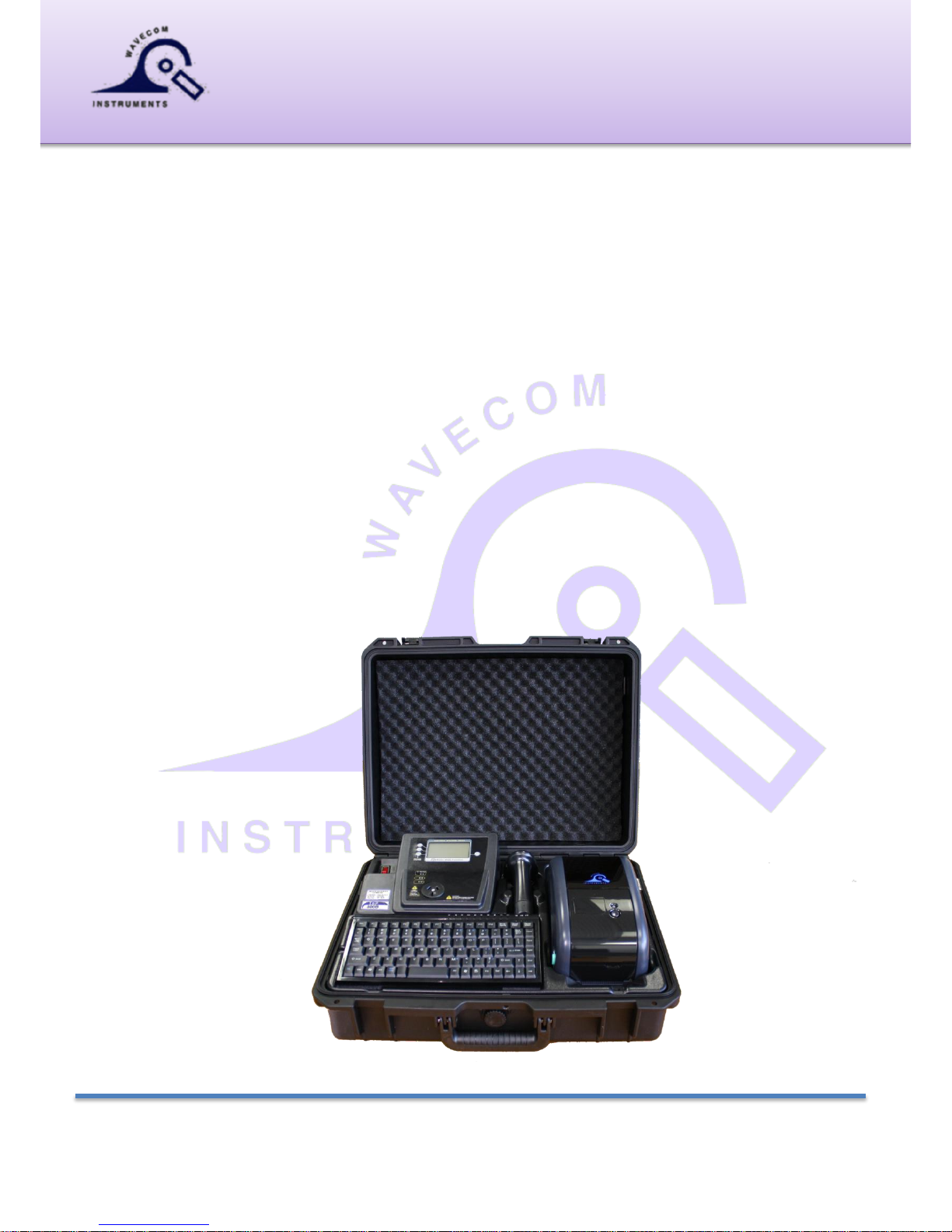
Fully Integrated TEST n PRINT UNIT
User Manual
TnP-500® 10Amp Model with wired Scanner
TnP-500X® 20Amp Model with wired Scanner
TnP-500W® 10Amp Model with wireless Scanner
TnP-500WX® 20Amp Model with wireless Scanner
TnP-500B® 10Amp Model with wired Scanner & Li Battery
TnP-500BX® 20Amp Model with wired Scanner & Li Battery
TnP-500BW® 10Amp Model with wireless scanner & Li Battery
TnP-500BWX® 20Amp Model with wireless scanner & Li Battery
Australian Designed & Manufactured to comply with testing requirements of
AS/NZS 3760:2010 Standards.
Adelaide
257 Grange Road, Findon SA 5023
Phone: (+61) 08 8243 3500
Fax: (+61) 08 8243 3501
Email: sales@wavecom.com.au
Web: www.wavecom.com.au
Melbourne
772A Station Street, Box Hill, Victoria 3128
Phone: 1300 793 301
Fax: (+61) 03 9897 4766
Email: salesvic@wavecom.com.au
Web: www.wavecomrentals.com.au
Perth
Unit 2/17 Casino Street, Welshpool, WA
Phone: (+61) 08 9353 1943
Fax: (+61) 08 9353 4319
Email: saleswa@wavecom.com.au
Web: www.wavecom.com.au
Page 2

Wavecom Instruments Fully Integrated Test N Print Unit - User Manual
2
Contents
Important Information ....................................................................................................... 4
In the box ..................................................................................................................................................... 4
Precautions ................................................................................................................................................. 4
Manufacturer Recommendations ................................................................................................................ 5
Safety Warning ............................................................................................................................................ 5
Competent Person ...................................................................................................................................... 6
Disclaimer Limited Warranty ....................................................................................................................... 6
Technical Information ....................................................................................................... 7
Class 1 (Earthed Appliance) Construction .................................................................................................. 7
Class 2 (Double Insulated) Construction ..................................................................................................... 7
Testing of Electrical Equipment ................................................................................................................... 7
Integrated Tests .......................................................................................................................................... 9
Supply Mains Test [Not available in Battery Mode, TnPB Series] ...................................................... 9
NCNT Test ............................................................................................................................................ 9
Visual Inspection (First Test) ..................................................................................................................... 10
Operating TnP 500 .......................................................................................................... 11
Powering on the Tester ............................................................................................................................. 12
Test n Tag Mode / Memory Mode ............................................................................................................. 12
Adding New Equipment ..................................................................................................................... 12
Adding a Site....................................................................................................................................... 13
Adding a User ..................................................................................................................................... 13
Auto Generate Barcode Function........................................................................................................ 14
Entering Items ..................................................................................................................................... 14
Retesting Equipment ........................................................................................................................... 16
Deleting Equipment ............................................................................................................................ 17
Reprint Tag without testing ................................................................................................................ 17
TnP Testing Menu – Main Menu A & Main Menu B .................................................................................. 17
Test Menu A – Function Flow Chart .................................................................................................. 17
Class 1 - Earthed Appliance Test – Menu A - F1 ............................................................................... 18
Class 2 Test - Double Insulation Test – Menu A - F2 ........................................................................ 19
Lead Test (Ext Lead Test) – Menu A - F3 .......................................................................................... 19
Test Menu B – Function Flow Chart .................................................................................................. 20
Power Test - Menu B – F1 .................................................................................................................. 20
Leakage / Run Test – Menu B – F2 [Not available in Battery Mode, TnPB Series] .......................... 21
RCD Test – Time Test / Ramp Test– Menu B – F3 ........................................................................... 22
Options Menu / Settings ............................................................................................................................ 26
Change Insulation Voltage .................................................................................................................. 26
Change Leakage Test Time ................................................................................................................ 26
Change Audio Settings ....................................................................................................................... 27
Change Result hold time ..................................................................................................................... 27
Change Battery Time-out settings – Only in TnPB series .................................................................. 27
Change Label Options settings ........................................................................................................... 28
Change Barcode Options settings ....................................................................................................... 28
Set Date / Time ................................................................................................................................... 29
Kill Switch .......................................................................................................................................... 29
Meter Mode ® [Not available in Battery Mode, TnPB Series] ................................................................... 30
SPECIFICATIONS TnP® Series ....................................................................................... 32
Wireless BARCODE scanners 1560P – for TnPW series ................................................. 32
Wavecom Thermal Transfer Printer ................................................................................ 36
Loading the media ..................................................................................................................................... 37
Loading the Ribbon ................................................................................................................................... 38
LED and Button Functions ........................................................................................................................ 39
Power on Utilities ....................................................................................................................................... 39
Self-test ..................................................................................................................................................... 40
Page 3

Wavecom Instruments Fully Integrated Test N Print Unit - User Manual
3
Dump mode ............................................................................................................................................... 41
Printer Initialization .................................................................................................................................... 41
Set Black Mark Sensor as Media Sensor and Calibrate the Black Mark Sensor...................................... 42
Set Gap Sensor as Media Sensor and Calibrate the Gap Sensor ............................................................ 42
Troubleshooting ......................................................................................................................................... 42
LED Status .......................................................................................................................................... 42
Print Problem ...................................................................................................................................... 43
Maintenance .............................................................................................................................................. 43
Important Information ..................................................................................................... 45
Restrictions to the transporting of LITHIUM ION products ........................................................................ 45
Optional Accessories ................................................................................................................................. 45
Disclaimer – E&OE .................................................................................................................................... 46
Scan this QR code to visit www.wavecom.com.au
(Use QR code reader app on iPhone / android phone)1
Scan this QR code to book manufacturer’s calibration / repair
service.
(Use QR code reader app on iPhone / android phone)
Scan this QR code to save contact card with Wavecom Instruments
contact numbers and email address for tech support – to your phone.
Simply scan the code on left, click save / done in your phone.
(Use QR code reader app on iPhone / android phone)
1
Brand names, logos and trademarks used herein remain the property of their respective owners. This listing of any firm or
their logos is not intended to imply any endorsement or direct affiliation with Wavecom Instruments Pty Ltd.
Page 4

Wavecom Instruments Fully Integrated Test N Print Unit - User Manual
4
Important Information
In the box
Integrated Test N Print System
User Manual/Quick Start Guide IEC Test Lead (500mm Orange)
WCM Keyboard USB A to USB B Interface Cable
Wavecom Scanner Serial Scanner Cable
Wavecom TT-040-50 1 x Roll /500 Labels - 1 x Resin Ribbon
WinPATS Software (Full Version - Asset Management) Earth Lead with Alligator Clip (1800mm black)
Self-Contained in Heavy Duty Case Locking IEC Power Cable (1800mm Blue)
Manufacturer’s 1st Calibration Certificate (Valid for 12 months from date of purchase)
Important: Please register your WinPATS Software and Test N Print Unit with the provided documentation or online via
our website www.wavecom.com.au
Precautions
Unique Locking Power Cable – For whole TnP Range
Please make sure yellow lever is pressed prior to removal of the locking power supply cable - 10A & 20A Models. Failure to do so,
combined with excessive force may damage the panel. This revolutionary locking, removable cable is intended not to dislodge during
test procedures. Note: 10A ver. plug illustrated. 20A ver. is similar.
[ Following are for TnP 500B series with internal lithium-ion battery.
Switch from battery power to mains power
To switch from battery power to mains power, simply plug in the supplied power cord and connect to mains. Unit will automatically
switch to mains. Turning off Main Red Neon switch on left top corner will turn off the unit completely.
Switching from mains power to Battery Power or Turning On /Off unit on Battery power
When unit is not connected to mains, simply press and hold ENTER button on the unit till unit starts. Use the same button to turn off
the unit. Mains Supply tests, Leakage tests and Meter Mode functions are not available on battery power. To perform RCD Tests, unit
is required to be connected to mains power. [Make sure that battery isolation switch located underneath the keyboard is ON all
the time while operating the unit & performing tests.]
To Charge the battery
Internal lithium-ion battery is of 97.92Wh, 6800mAh. It gets charged automatically while unit is connected to mains. It takes around
four hours to charge it fully. While charging, a battery symbol on top right corner of LCD screen will show how much it has been
charged and how much is left.
While it’s charging and user is not using the unit, display can be turned off by pressing and holding the same ENTER button. This will
bring a charging information display and decrease the brightness of LCD screen. Once battery is full charged and it is still connected
to mains, battery symbol will convert to plug symbol. It is advised not to put unit to charge when it is unattended or overnight.
Warnings: Operating Environment: Charging – 0ᴼ to ~45ᴼC; Discharging - -20ᴼ to ~ 60ᴼC.
Please keep unit away from extreme exposed heat or extreme warm environment where typical temperature is above 60ᴼ. Please
keep unit safe and secured from free-fall or physical pressures, trauma or drop from heights.
Please do not open Battery compartment which is located behind the printer, unless user suspects that battery is damaged or smoke
is detected. Robust design and studies has been carried out while unit was under development and all possible safety concerns are
taken care of in this regards. It is still advised not to be opened. Damaged lithium ion batteries are not allowed for transportation.
Please speak to support team at Wavecom @ +61 08 8243 3500. Battery can simply be removed by opening a black cover behind the
printer, which should only be done in case of damage.
If sending unit for calibration, please turn off the battery isolation switch which is located underneath the keyboard.
Storage Warning: Please store the unit as per operating environment, do not leave unit where temperature can rise above 60ᴼ C]
For units with wireless scanner, please note that user have to press and hold yellow trigger button on scanner till It lights up and
beeps. Long beep will confirm the connection between unit and scanner. Please let scanner charge for some time once in a while,
when unit is connected to mains. Wireless Scanner charges through the dock, please make sure that scanner is docked properly and
red LED flashes on scanner, indicating charge mode. Scanner battery and internal main TnP Li battery charges simultaneously while
being on Mains power, in case of TnPBW & TnPBWX units.
Page 5
Wavecom Instruments Fully Integrated Test N Print Unit - User Manual
5
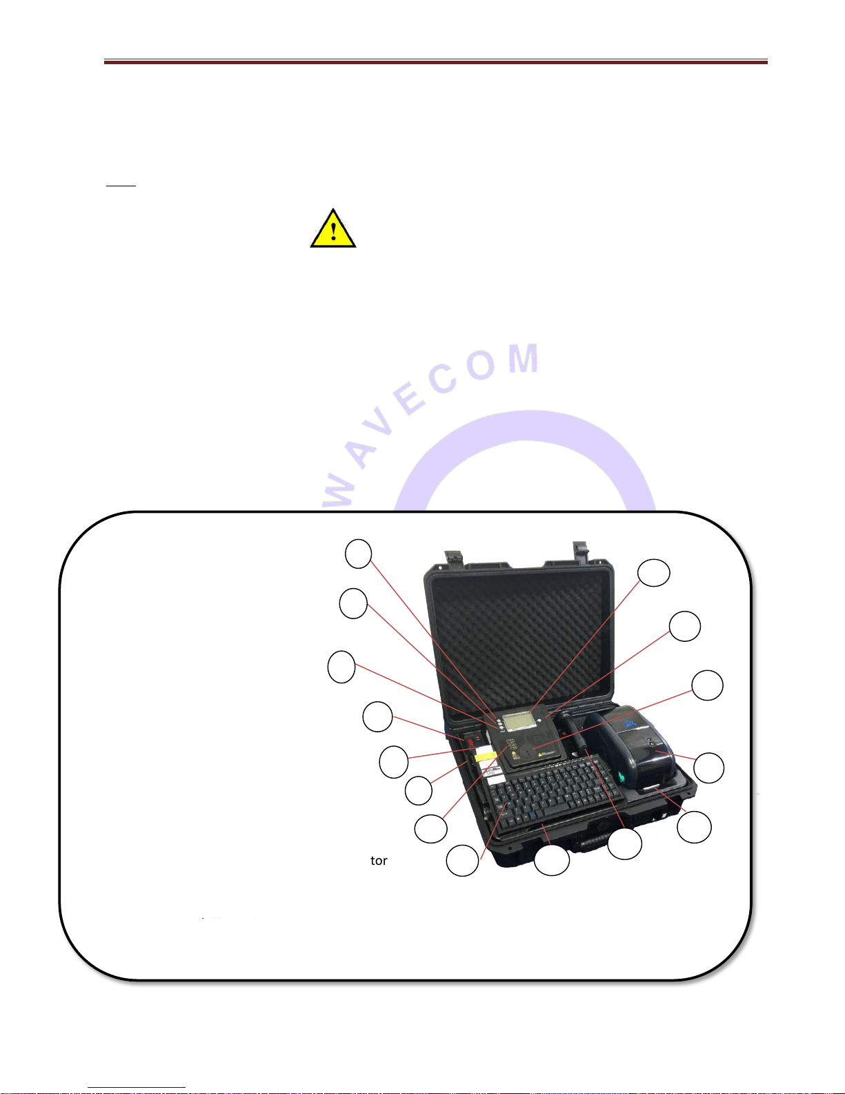
Instrument description
1. Function Key F1
2. Function Key F2
3. Function Key F3
4. On/Off Switch
5. TnP-500 Power Socket
6. Appliance IEC Test Socket
7. LED Light Indicators
8. Keyboard
9. Storage Area (Under Keyboard)
10. Barcode Scanner
11. Label Chute
12. Wavecom Printer
13. AS/NZS 3112 Appliance Socket
14. Enter/Return Key & Pass/Fail LED Indicator
15. LCD Results Screen
Manufacturer Recommendations
Calibration: The AS/NZS3760:2010 Standard recommends a routine calibration / verification of this unit to ensure the accuracy
of readings on a 12-monthly basis, or as prescribed under any additional local Regulatory requirements.
Note: Only Wavecom Instruments or its Authorised Service Agents are permitted to repair and Calibrate this Instrument.
Failure to perform unauthorised service or repair may void all warranties and Calibration Status.
Safety Warning
This 4th Generation TnP series of products have been designed to meet stringent safety requirements, however no device can
completely protect persons from the consequences of incorrect use.
The testing of Electrical appliances requires that extra care and caution is taken at all times to ensure personal safety.
The Manufacturer also advises that appliance testing should be conducted by a Competent and suitably trained person, as
referred to under the current Standard AS3760:2010, as well as any additional legislation or rulings in different states.
If in doubt, the manufacturer suggests the user contact their responsible Authority.
For maximum safety, always ensure that the following advice is followed:
The equipment being tested is in good condition / visual check.
All user instructions are followed.
Double check power supply connections. (note LED status)
Always use specified fuses and protection devices.
Do not use leads that require repair or are damaged.
If you are unsure, call a licensed Engineer/Electrician.
* See P.6 AS/NZ 3760:2010 def.
Fully Integrated Test N Print Unit 10A ver. shown
5
6
1
2
11
7
14
3
4
10
12
9
8
Note: 10A model shown - 20A model Includes Circuit Breaker next to power
13
Page 6
Wavecom Instruments Fully Integrated Test N Print Unit - User Manual
6
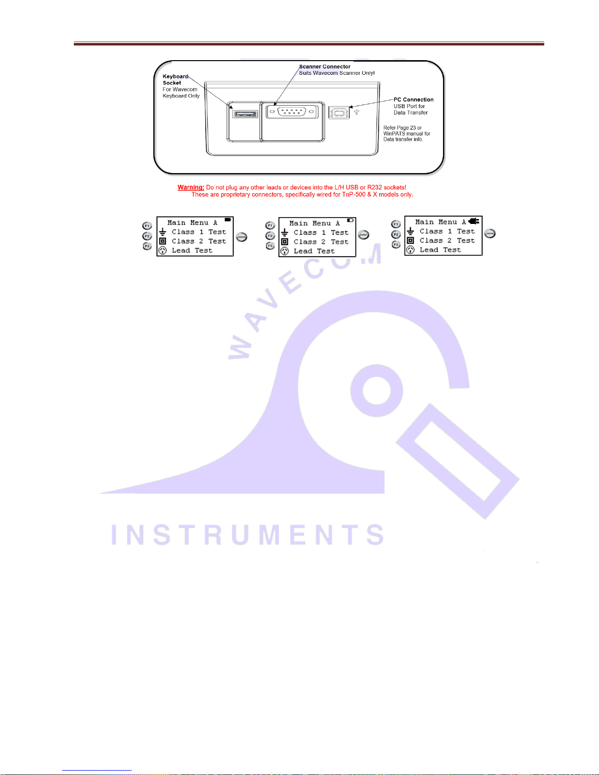
Battery Symbols on TnP Screen: If unit is powered from battery, a solid battery symbol will show status of charge left. If
charging, battery symbol will be interactive and live according the charge status. If unit is fully charged and still connected to
mains, battery symbol will change to plug symbol.
Competent Person
To ensure that all electrical equipment or devices are inspected, tested and tagged correctly, regulations require that a
‘competent person’ such as a Licensed Electrician be employed to perform the required tests. Please refer to the above
definition as described in the current AS/NZ-3760:2010 Standard and in addition, to any other local legislation or jurisdictions
as may be relevant in your State.
EXAMPLE:
A person competent to undertake Inspection and Testing of electrical equipment must have:
Knowledge and practical experience of electricity and its hazards.
A clear understanding of precautions to avoid danger.
The ability to recognise at all times whether or not it is safe for work to continue.
The ability to carry out visual examinations of electrical equipment.
The ability to distinguish between electrical equipment that is double insulated and equipment that is earthed as well
as being able to identify the appropriate test for each type.
The competency to safely carry out the Earthing Continuity, Insulation Resistance or Leakage Test and RCD tests on
electrical equipment.
The knowledge of how to use the relevant testing instruments, interpret and record the results for compliance with
the Standard/Workplace requirements.
The knowledge to be able to correctly recommend the frequency of testing required.
Due to the potential hazards of electrical testing, due care must be taken at all times.
Disclaimer Limited Warranty
The Manufacturer warrants its products against defects in materials and workmanship for a period of 12 months from the date of
purchase. During the warranty period, the manufacturer will repair (or at its option replace at no charge) the product that proves to be
defective. This warranty does not apply if the product has been damaged by accident, abuse, misuse or mis-application or as a result of
service or modification by anyone other than manufacturer of the TnP.
The TnP product range of devices or its manufacturer IS NOT RESPONSIBLE FOR INCIDENTAL OR CONSEQUENTIAL DAMAGES RESULTING
FROM THE BREACH OF ANY EXPRESS OR IMPLIED WARRANTY, INCLUDING DAMAGE TO PROPERTY AND TO THE EXTENT PERMITTED BY LAW,
and DAMAGES FOR PERSONAL INJURY. The Distributors of this product cannot assume liability or responsibility for any loss or damage
resulting from the use of this device.
The TnP manufacturer reserves the right to discontinue models, change specification, price or design, at any time without notice or
obligation.
Test n Print
Interface Panel
Located under
Keyboard
Page 7

Wavecom Instruments Fully Integrated Test N Print Unit - User Manual
7
Technical Information
Class 1 (Earthed Appliance) Construction
(Single basic insulated and protectively earth equipment)
This type of product design provides two safety barriers between all live conductors at dangerous voltages and the equipment
user.
The provision of basic insulation between exposed metal parts and live parts is the first barrier to provide basic protection
against electric shock.
The second safety barrier is by the connection of exposed (accessible) conductive (metal) parts to the protective earthing
conductor (earth wire) in the fixed wiring of the device/Installation.
The protective earthing terminal of the equipment must be marked with the word "earth" or the symbol "E" or the symbol for
Earth Terminal or Protective.
To perform this test, a continuous earth loop must be made between the exposed conductive material (metal) and the TnP
appliance tester. This is done by means of connecting the earth lead with the crocodile clip/probe attached to a GOOD earth
point (paint & coatings will not provide effective connections) and the DUT (Device Under Test) plugged into the TnP appliance
testers’ DUT socket. The Maximum allowable limit is less than1.0 (ohm).
Refer Page 7 on how to extend time to get a true earth connection (Unique Earth Bond Test Feature)
Class 2 (Double Insulated) Construction
(Double insulated equipment)
This method of construction employs two safety barriers comprising two layers of insulation between dangerous voltages
and the user of the equipment.
The first layer of insulation is formed around the live conductor and is termed ‘the Functional Insulation’.
The second layer of insulation is termed ‘the Supplementary Insulation’. In Class II equipment, protection against electric shock
does not rely on basic insulation only, but has additional supplementary insulation such as double insulation or reinforced
insulation provided, there being no reliance on precautions in the fixed wiring of installation.
Class II equipment is marked with the words "DOUBLE INSULATION" or the symbol
For double insulated under Safety Symbols:
Note 1 – Double Insulation is insulation comprising both basic and supplementary insulation.
Note 2 – Reinforced Insulation is a single insulation system with a degree of protection against electric shock, which is
equivalent to double insulation.
Testing of Electrical Equipment
Many testing personnel have some reservations in testing sensitive, electronic equipment using a 500V DC insulation test.
There is a perceived fear of causing internal damage from over voltage. With the introduction on the TnP Range of appliance
testers, these concerns are alleviated.
The TnP Range of electrical portable appliance testers is safe to test electronic equipment as the tests are carried from ActiveNeutral (shorted by a relay inside the tester) to Earth. No dangerous voltages pass through in this mode to the internal
Page 8

Wavecom Instruments Fully Integrated Test N Print Unit - User Manual
8
components of the DUT (Device Under Test). If these tests are done using an Insulation Tester only and the user tests Active
to Neutral, this would be a cause of potential damage, this is why the TnP product range is far safer to use.
Some changes may be required in certain configurations where fitted surge protection devices (MOV's) in the DUT may cause
a failed test result. Applying 500V in this these situations can cause the surge protection devices to trip, therefore conducting
the applied voltage to earth, thus showing a failure of insulation. In these instances the test voltage should be changed to 250V
then retest. If DUT still fails, check with the DUT Operators Manual or an electrician. [for details see - ‘Double Insulation Test’
250/500VDC to change test voltage].
Under these circumstances, it would be difficult for any damage to occur to either the surge protection device or the DUT, as
there is insufficient current generated by the TnP test unit.
Leakage Test:
If there are any doubts with insulation testing of the equipment, the standard (AS/NZ3760 since 2001) allows for an alternative
test method. A Leakage Test can be performed instead. (The TnP – Series are designed to perform these tests).
NOTE: 10Amps MAXIMUM Resistive Load only (Standard TnP Series units).
A Leakage Test applies power to the Device Under Test (DUT) and measures the imbalance of leakage current from the DUT
between the active and neutral conductors. The leakage is tested to the limits specified in the standard and a Pass/Fail result
as well as a digital reading is provided to ensure that the user gains as much information as necessary.
Earth Continuity Test, commonly called EARTH BOND TEST:
Note: Part of normal (Class 1 test) procedure
Use supplied IEC–Croc clip lead or optional accessory ‘WCM-Probe kit’.
The TnP.500 unit conducts earth continuity tests at Approx. 200mA. Continuity tests at higher currents are not required or
recommended on certain equipment as this may cause severe damage or premature failure to the Device under test (see
AS/NZS 3760:2010).
Unique Earth Bond Test Feature
Note: Test time with the new TnP-500 series can now be user controlled. This function enables testing personnel to extend
the Earth Bond test time by 30 second increments!
This is achieved by momentarily pushing the ENTER button once, during the test.
The TnP-500 will then add 30 seconds to the test time for ENTER button press.
This feature has been incorporated to provide extra time to achieve an adequate physical connection, or confirm any possible
INTERMITTENT issues. There may be situations where the condition of equipment, coatings applied, or suspect wiring breaks
may alter the earth connection path of the device under test.
Benefit to test personnel is to save time by not having to continually repeat tests in a less than perfect situation.
3 Phase Testing: *Optional equipment required
3 Phase appliances can be tested by the TnP series appliance testers. As the insulation tests are from Phase to Earth, only a
500V insulation test is required. This test may be carried out by using the optional adaptor ‘WCM-3PH-MADP’ [See ‘Optional
Accessories’ for details.]
Note: The TnP500 series will not perform a 3 Phase Leakage test.
Contact Wavecom Instruments Pty Ltd for information on appropriate testers.
Switching between 250V & 500V Test
To change the test voltages, when in Main Menu A; Press Enter and F2 together to enter in settings. Select “Change
Insulation Vol” and press enter. Select either 250V or 500V.
Please note, TnP starts default to 500VDC, and will revert back to that when restarted.
Page 9
Wavecom Instruments Fully Integrated Test N Print Unit - User Manual
9
Integrated Tests
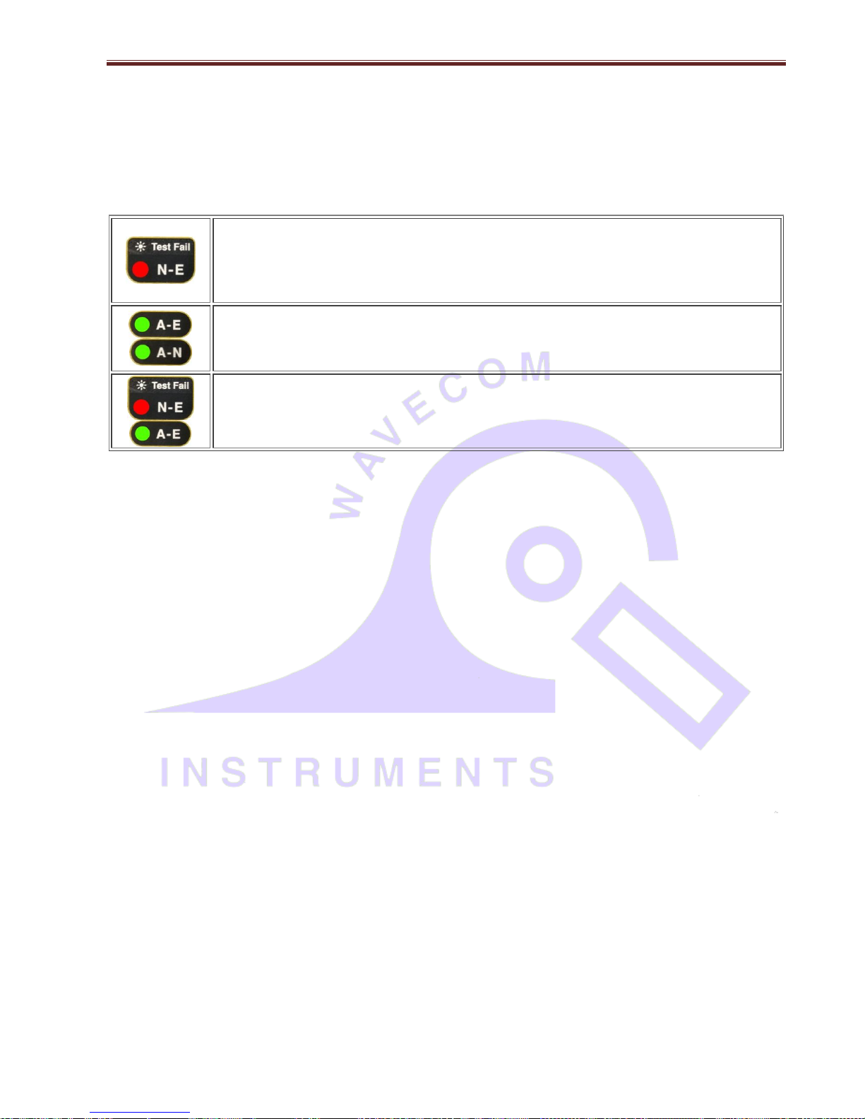
Supply Mains Test [Not available in Battery Mode of TnPB Series]
The Supply Mains Test checks the polarity and connectivity of the mains supply by LED's. This test is also a part of all the
testing functions of this unit.
If the N-E (red) light is on and you need to conduct load/leakage tests DO NOT CONTINUE. If you are
carrying out standard Insulation and Earth Bond tests, it is generally safe to continue. This light will glow
if a voltage difference lies between the neutral and the earth, or if no earth is connected to the TnP- Series
supply. (If working with a generator or inverter, this is most likely to occur and you may need to consult
an electrician before proceeding).
If both the A-E & A-N (green) lights are on but not the N-E (red), mains supply test is ok, continue to test.
ALL GOOD !!
If both of the N-E (red) & A-E (green) lights are on, consult an Electrician, as there is a fault with the Mains
Supply.
Note: While in Battery mode, all LEDs will be off as no mains connected and supply mains test is not
carried out.
NCNT Test
(No Connection No Test)
The TnP – Series appliance testers ensure that the appliance is plugged in and switched on. This test is also a part of all of the
testing functions of this unit.
This test function ensures that the appliance is plugged into the TnP appliance tester and that it is switched on. If the device is
not plugged in and the TnP appliance tester detects that no device is present, plug in to continue the test or confirm ‘QUIT’ to
return to the main menu.
If for some reason the NCNT circuit does not detect the device but it is actually plugged in and turned on, the operator will
need to override the NCNT function.
To do this Over Ride Press F3 (Done with User Discretion)
With an emphasis in the Standard AS/NZ3760:2010 for carrying out the live testing the TnP - Series appliance testers will
indicate for you to check if the device is plugged in and switched on. If the device is not plugged in and/or recognised, it may
require a live test therefore making it necessary for the operator to carry out a full functional Leakage Test (Available on all
models of TnP – Series).
This function is to ensure that correct testing procedures are carried out in accordance with the Standard AS/NZ3760:2010.
*Optional
Note: When using 3-Phase adaptors the NCNT function will need to be over ridden by pressing the ‘OK’ key prior to the TnP
appliance tester performing the assigned test. Some single-Phase appliances controlled by contactors will also require manual
over ride. In some instances, holding the ‘ON’ button will enable the NCNT function to work normally.
Page 10

Wavecom Instruments Fully Integrated Test N Print Unit - User Manual
10
Visual Inspection (First Test)
VISUAL INSPECTION HAS TO BE DONE BEFORE ANY OTHER TEST IS CARRIED OUT USING ANY OF THE RANGE OF TnP APPLIANCE
TESTERS
There is no damage or component defects to the accessories, plugs, outlet sockets or connectors (physical).
There are no cracks &/or abrasions.
There are no exposed inner cores or conductors (flexible) and the supply cords are not twisted or distorted.
Any Fuse / Over load protection components (if fitted) are checked.
All labels, markings and warning indicators (of the maximum load to be connected to the device) are legible and intact.
The insulation is not damaged in any way i.e. melted, cuts or abrasions. There are no iron filings in the insulation.
There is no insulation tape on the lead.
Any flexible cords and/or leads are effectively anchored (glands and grommets intact).
All covers or guards are in place and secure as intended by the supplier/manufacturer.
All safety devices and systems are in good working order. (i.e. overload latches & buttons).
No dust &/or dirt obstructs any exhausts or ventilation outlets.
All controls are working properly and are secure and aligned.
Important: If result is a FAIL!!
If any Equipment FAILS ANY of the above, it should be deemed to have FAILED the Visual Test, and therefore no other tests
need be performed. If this is the case the Equipment should be tagged with a DANGER TAG and removed from service. It is
recommended by the manufacturer and distributor of this product that it SHOULD NOT BE RETURNED TO SERVICE. To do so
would be considered unsafe.
The Wavecom series of appliance testers have been designed & manufactured to exceed and comply
with the AS/NZ:3760 standard, and to aid the end user with simple everyday electrical symbols that
they can identify with which will allow them to start the testing regime quickly and efficiently, without
any complexity as illustrated below.
Page 11
Wavecom Instruments Fully Integrated Test N Print Unit - User Manual
11
Operating TnP 500
Follow the simple flow chart as per the requirements.
CAUTION
Unplug all leads except power cord when you turn on the unit as unit has automatic system check feature that automatically
runs every time on unit start-up. Make sure all peripherals, such as keyboard, scanner and printer are connected before turning on.
Turn on from mains power - Connect Blue power cord and use Power On/Off switch - refer diagram on p.5
Following is for TnPB series.
[Turn on/Off from internal Battery
- Press & hold Enter button on tester till screen lights up / or till unit shuts down. Unit will operate
from internal 97.92Wh 6800mAh lithium ion battery and can perform range of safety tests. Meter Mode®, Leakage tests and RCD test
can only be performed while connected to mains due to obvious reasons.
Switch from Battery to mains - Simply connect to mains and turn on power on-off switch on tester, unit will operate from mains and
will charge the internal battery and wireless scanner battery automatically. Turning off Power On/Off switch while connected to mains
power, will turn off the unit and stop charging internal battery.
From mains power to battery - When user disconnects power from mains, unit will get switched off. Turn unit on from battery by
pressing and holding enter button on tester.
While performing RCD tests, unit will stay on battery power while RCD trips to disconnect mains power and let user print the tag or
perform the next test, simply reset the RCD which will restore the power back to unit; unit will then swiftly move to mains power
from battery automatically without shut-down, and let user re-perform RCD Test.]
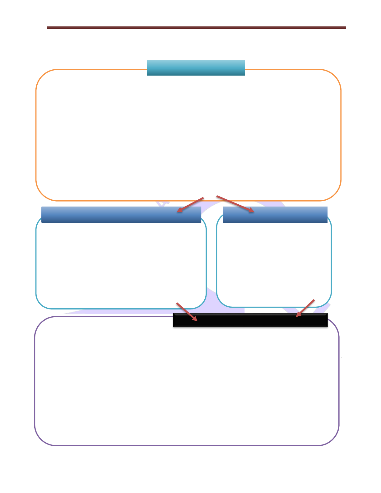
Tester starts in this mode by default
Use Keyboard, Scanner to Add user, enter site details and perform
tests, save results in onboard memory, edit/ delete previous records,
print / reprint tags and more.
search barcode by scanning / using keyboard; or create new barcode,
enter sites / user / location / equipment details [Page 12]. Once done,
keep pressing enter button to take tester to Main Test Menu A. Toggle
between Menu A and Menu B by pressing enter key.
CAUTION Press and hold of Enter
Button at New/Search Barcode
screen will turn off the unit if unit is operating from internal battery-
TnPB series.
Press and hold F3 while turning on the unit.
This will take unit straight to Main Menu A.
CAUTION
Keyboard, scanner & printer are
unavailable in this mode. Quick tests
performed in Tester mode will not be saved to
memory. No details for equipment /
site/location etc will be required / recorded.
Perform quick tests - No tag-printing
Use enter button to switch between Menu A and Menu B.
While in Main Menu A, use F1, F2 & F3 to perform Class 1 test, Class 2 Test and Lead test;
While in Menu B, Use F1, F2 & F3 to perform Power test, leakage test & RCD test.
When in Test and Tag (TnT) / Memory mode, after performing test, Tag will be printed automatically and results will be saved.
When in Tester mode, only quick tests can be performed through tester buttons. Keyboard / scanner/ printer can’t be used.
To use Meter Mode®, Press and Hold F3 while in Menu A.
Meter Mode® Displays electrical parameters from a power outlet source or from the appliance under test.To exit back to menu A, press
and hold Enter as displayed on screen.
Typical use of Meter Mode® can include checking ratings & parameters of appliance and compare them with labelled ratings of
appliance.
To go to options / settings Menu, Press Enter and F2 together while in Menu A
To change Insulation Voltage, Leakage test time, Audio options, Data results screen display hold time, labels options, Barcode options,
Battery operation time-out settings.
CAUTION ‘Press and hold Enter Button’ will turn off the unit if unit is operating from internal battery – TnPB series
Main Menu A / B
Test & Tag Mode / Memory Mode
Tester Mode
TnP 500
Page 12

Wavecom Instruments Fully Integrated Test N Print Unit - User Manual
12
Powering on the Tester
Please above flow chart to power on the unit.
When the tester is powered on, the scanner will beep a few times indicating the scanner is also powered. If no beep
is heard check the PS2 connections from the tester, in case of wired scanner. When wireless scanner is provided,
keep pressing yellow button on wireless scanner till it starts and makes beeping noise that indicates it is connected
to the unit.
Initially the printer’s status light will be orange but after about 5-10 seconds it will change to green. The tester will not
print unless the printer light is solid green. A flashing red status light can indicate a media or general printer fault.
Note 1: If the TnP stays locked on the logo screen please check the connectivity of keyboard & scanner cables. The
TnP unit will not work with scanner only connected. The TnP system requires either Keyboard only, or both Keyboard
& Scanner to be connected.
Note 2: If no devices are connected to the interface, the unit will function as a normal TnT tester.
The TnP units have Memory. There is an inbuilt flash memory and a real-time clock. This gives the ability to store
up to 5,000 records, which can include items from 16 different sites and 6 different users. This will help to increase
the efficiency and pace of testing. The TnP units (with memory) have two operating modes:
TnP tester mode only, no peripherals (Keyboard, Scanner or Printer) connected
Test and Tag / TnT mode, all devices connected & on, allowing testing, scanning, retrieval & printing
The TnT mode is determined if a keyboard is connected. If there is no keypad / scanner detected, then the TnP will
start in tester mode by default, taking to Main Menu A. If the keypad & scanner are present, then the new barcode
screen will be loaded, in TnT mode.
CAUTION: All peripherals are supposed to be connected when unit is turned on. If keyboard / scanner were not
plugged in when unit turned on in TnT mode, tester will not connect to keyboard / scanner as “ Active / Hot
connection”. Please connect all peripherals, and turn off the unit. Restart the unit, once all connected.
Test n Tag Mode / Memory Mode
TnP500 starts in memory mode by default. Keyboard, scanner and printer are all integrated in this mode to
aid user to create / save equipment & sites with relevant details into on board memory. Test results are
saved and tags are printed at the end of test. Tags can also be reprinted from memory.
The test sequence starts with option of creating a barcode or searching a barcode from the memory. A site
and user has to be added before testing can be done.
Adding New Equipment
The following must be done before testing:
Create a site or use and existing site.
Create a user name to under the users list.
If auto generate number is used the initial number must be set correctly.
If you are adding equipment to an existing site please make sure that the correct site is displayed. If the
wrong site is displayed the equipment will be assigned to the wrong site.
When the testers memory has been erased it will look like the following screen.
Page 13
Wavecom Instruments Fully Integrated Test N Print Unit - User Manual
13
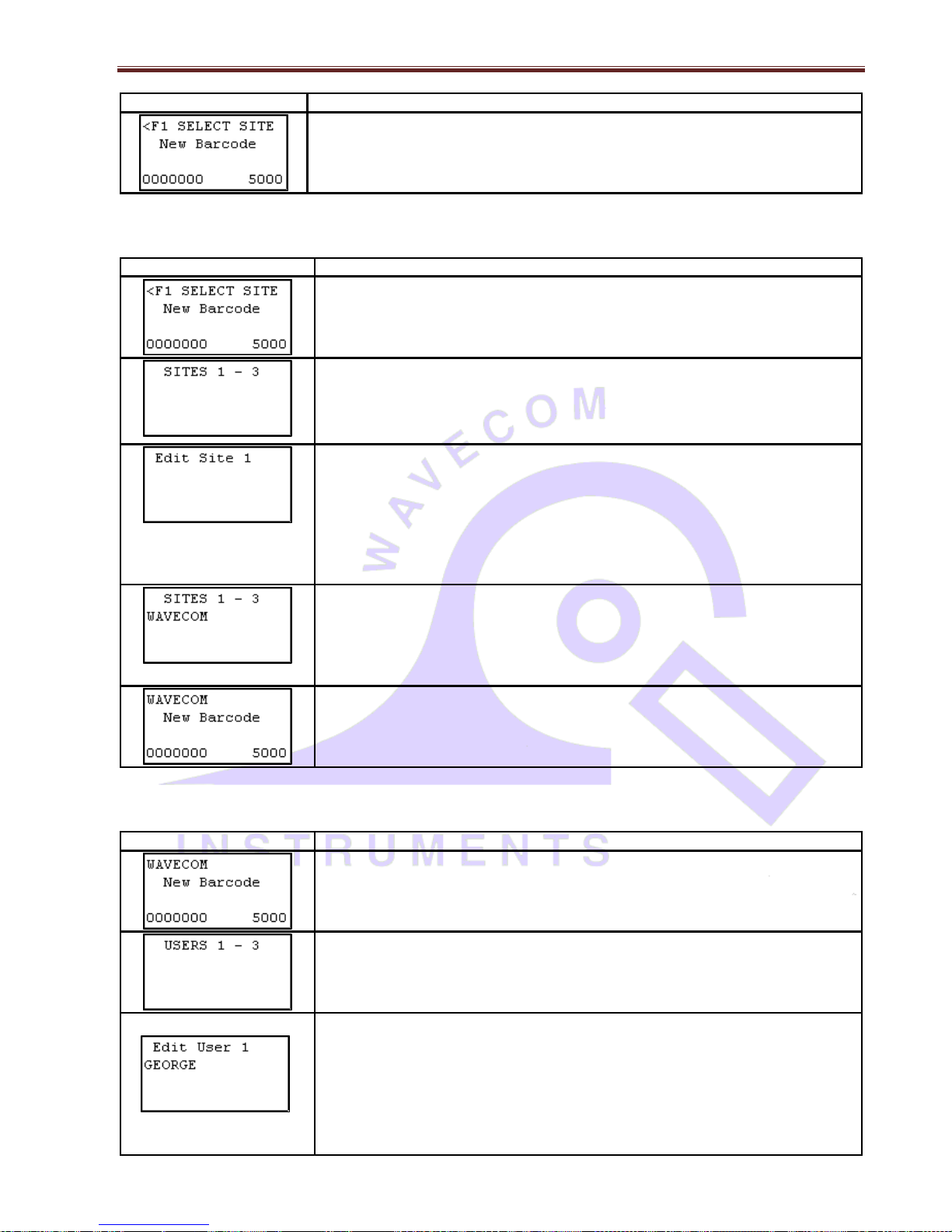
Screen
Instruction
When the initial screen in memory mode operation is displayed. A site and user must
be entered before testing can be done. When using the TnT for the first time, < F1
Select Site will be flashing in the top region of the screen.
Adding a Site
Screen
Instruction
From the initial screen, press F1. Don't hold the F key, this will select a different
function.
The TnT can hold up to 16 sites. To scroll through the sites, press enter. 3 sites
will be shown on each screen. Each site corresponds to an "F" key, for example
Site 1 = F1. To edit a site, hold the corresponding "F" key for 2 seconds. If the Site
has a * symbol next to the name then the site name cannot be altered. This site was
uploaded from WinPATS and needs to remain the same.
Using the keypad, enter the name of the site. The Keypad operates in 3 modesAlpha, Numeric and Predictive. When an editable screen is entered, there will be
an ALP, NUM or PRE in the top right hand corner of the screen. If you are using a
full size half size keyboard then the 3 modes don't apply. Leave the text on ALP
mode. Once the details have been typed in press enter to return.
Note: Predictive mode will only work if a dictionary has been uploaded from
WinPATS MX. Once a site has been entered, press enter.
Once a site has been entered, the 'F' buttons are used to select the site. For
example to select site 1, F1 would be pressed.
Once a site has been selected, the TnT will return to the initial screen and the site
that was selected will be shown in the top left hand corner of the screen.
Adding a User
Screen
Instruction
From the initial screen, press F2. Don't hold the F key, this will select a different
function.
The TnT can hold up to 6 users. To scroll through the users, press enter. 3 sites
will be shown on each screen. Each site corresponds to an "F" key, for example
User 1 = F1. To edit a user, hold the corresponding "F" key for 2 seconds.
Entering a user is the same process as entering a site, please refer to the Adding a
Site steps above, Note: The user name will not appear on the initial screen once
selected.
Page 14

Wavecom Instruments Fully Integrated Test N Print Unit - User Manual
14
Once a user has been entered, the 'F' buttons are used to select the user. For
example, to select user 1, F1 would be pressed.
Auto Generate Barcode Function
If required, the auto generate barcode number can be set before testing. The auto generate is always displayed in
the bottom left hand corner of the new barcode screen.
Screen
Instruction
The TnT incorporates an auto generate barcode function which allows barcodes to
be generated sequentially after a barcode has been specified, for example: the
specified barcode is 1000 so the next barcode to be generated will be 1001, 1002,
1003 etc. This can be accessed by holding F3 for 2 seconds on the Barcode Entry
screen.
Once the auto generate menu has been accessed, the user can specify how many
digits they want in the barcode. The auto generate function allows a minimum of 2
and a maximum of 7 digits in the barcode to be generated. To increase the number
of digits in the barcode, press F1. To decrease the number of digits in the barcode,
press F2. To proceed, press enter, or to return to the Barcode Entry screen, press
F3.
If enter was pressed, the user can now set the barcode that will begin the
sequence. Key in a barcode and press enter to continue, or F3 to return the Barcode
Entry screen.
If enter was pressed, the user can specify whether or not to use leading zeros in the
auto generated barcode. For example: If the user selected 7 digits in the barcode and
entered 1000 as the barcode, the barcode will be 0001000 if leading zeros are
enabled. To enable leading zeros, press F3. To disable, press enter. The current
barcode that will be generated is displayed in the bottom left hand corner of the
Barcode Entry screen.
The current barcode that will be generated is displayed in the bottom left hand corner
of the Barcode Entry screen.
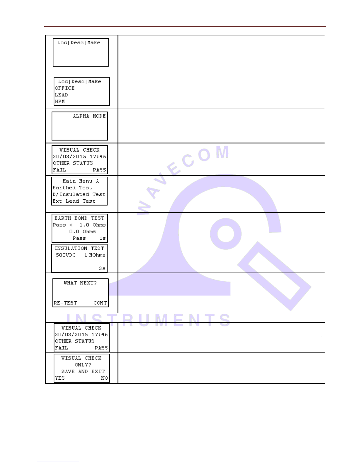
Entering Items
Screen
Instruction
Type in the new barcode or press F3 quickly to choose the auto generate number.
Once a barcode has been specified, items can be entered. If the screen displays
"search barcode" press enter to switch to new barcode. There must be no numbers
entered in to switch between the two modes.
Page 15
Wavecom Instruments Fully Integrated Test N Print Unit - User Manual
15
A selection of details can be entered for an item. Details include; location, description,
make, model, serial number, asset number, frequency of test and notes. Each
heading relates to an 'F'; e.g. Loc = F1, Desc = F2 and Make = F3. Only 3 items are
displayed at one time. To scroll through the various details, press enter key. By
continually pressing enter you can loop back to the first 3 items. Please make sure
location and description are filled out and check to see that the frequency is correct.
Once the details are entered, hold the enter key for 2 seconds to move on to the
visual check screen.
Entering an items details is the same process as entering sites and users, please refer
to the Adding a Site/User steps above. Ensure that test frequency for the item is set
in accordance with the AS/NZ 3760 Standard
After the item, has been visually inspected, there is 1 of 3 options that can be selected;
Out of Service (F2), Fail (F3) and Pass (enter). If Out of Service or Fail is selected
the result will be saved and the TnT will revert back to the barcode entry screen. If
you have a zebra printer a tag will be printed. If the test is a visual check only then
press (enter hold). See below for details.
If the item passes a visual inspection and pass is selected, testing can begin. Select
the correct test based on the appliance type.
TnP Testing Menus, Main Menu A and Main Menu B are explained in later
sections at page 16.
Once test has been completed the results are displayed.
To test the item again, press (F3). This will take you back to the main menu A
screen. From here you can choose a test class. You would use this for example if
testing power boards. To complete the test, press enter. This will take you back to
the new barcode screen.
If you have a zebra printer, a barcode will be printed once (enter) is pressed.
Visual Check Only Option
Items can be passed with a visual check only (no testing required). You must be at
the visual check screen shown on the left. To do a visual check only press and hold
(enter) for 2 seconds.
Pressing (enter) will take you back to the visual check screen. Pressing (F3) will
complete the test. Print out a tag if you have a zebra printer. Then go back to the
new barcode screen.
Page 16
Wavecom Instruments Fully Integrated Test N Print Unit - User Manual
16
Retesting Equipment
The following must be done before retesting:
A site must exist in the tester with records. A site is usually uploaded from WinPATS.
The correct site must be displayed on the first line of the new / search barcode screen. If the incorrect site
is displayed no equipment will be reported when scanned. To change see the add sites section.
The correct user must be selected from the users list. A user is important because it give a reference to the test
results in WinPATS. It is also the user that is displayed on the tag. If there is no users create a users as described
in the add equipment section or upload the users list from WinPATS.
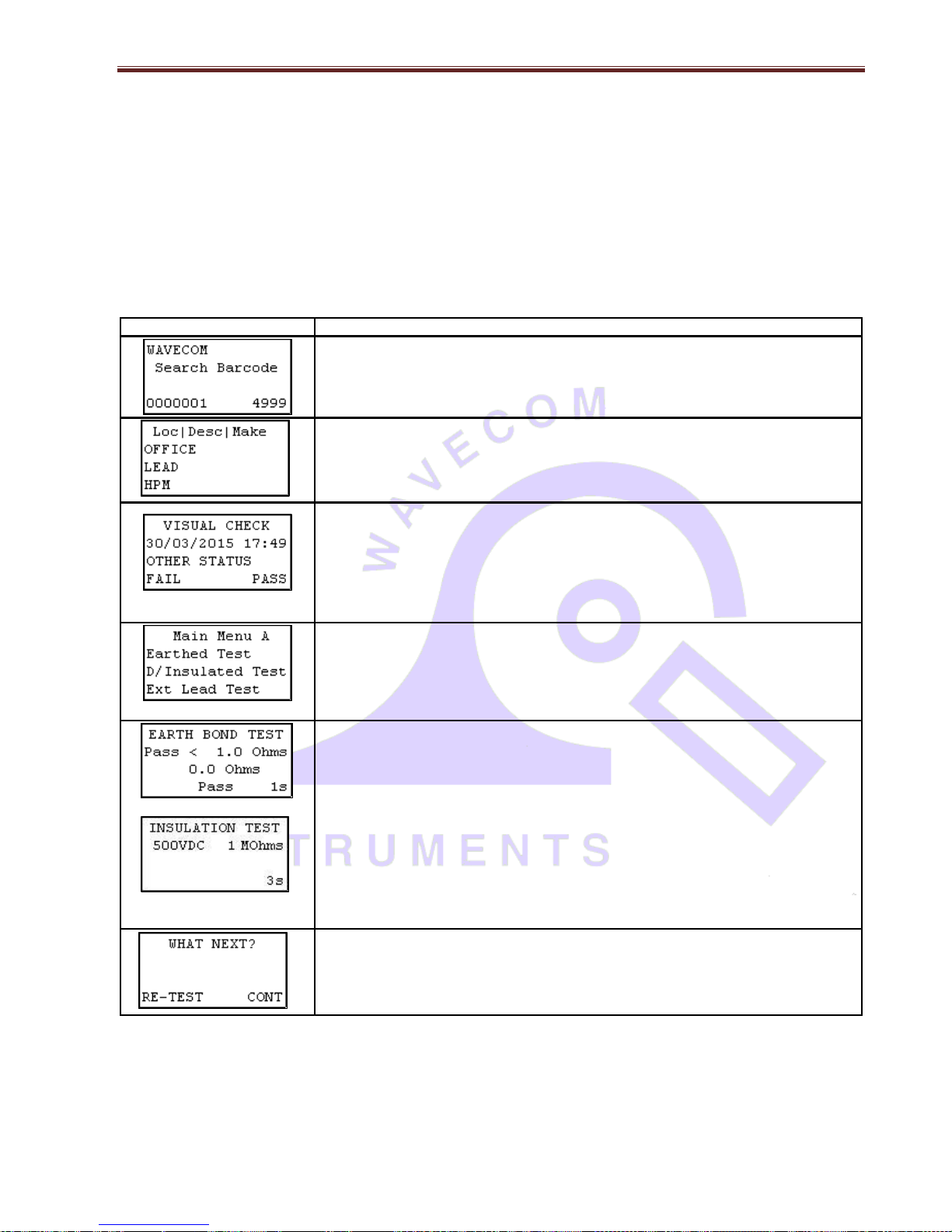
Screen
Instruction
Type in or scan the barcode number to be searched and press enter. If the screen
displays new barcode press enter to switch over. The screen can only be switched if
there is no entry.
The existing record details will be shown. Any changes made here will be updated
once the site is downloaded in WinPATS. If nothing needs changing hold the enter
key to proceed to the next screen.
After all item details have been entered, hold the enter key for 2 seconds to proceed
to the Visual Check screen. After the item has been visually inspected, there is 1 of
3 options that can be selected; Out of Service (F2), Fail (F3) and Pass (enter). If
Out of Services or Fail is selected the result will be saved and the TnT will revert
back to the barcode entry screen. If you have a zebra printer a tag will be printed. If
the test is a visual check only then press (enter hold). See add equipment for
details.
)
If the item passes a visual inspection and pass is selected, testing can begin.
Once test has completed the results are displayed.
To test the item multiple times press (F3) this will take you back to the main menu A
screen. From here you can choose a test class. You would use this for example if
testing power boards. To complete the test press (enter). This will take you back to
the search barcode screen. If you have a zebra printer a barcode will be printed
once (enter) is pressed.
To download records using WinPATS software, please refer to the Downloading Records section of the WinPATS
manual
Page 17

Wavecom Instruments Fully Integrated Test N Print Unit - User Manual
17
Deleting Equipment
If for some reason a record needs to be deleted it can be removed from the search barcode screen. This feature
removes the whole record and not just the test results. If a record is deleted and replaced it might create a new
record when downloaded in WinPATS. This is because the record details didn't match the original ones. Multiple
items cannot be deleted at the same time. It is recommended to use Winpats for deleting equipment, as it is
very easier that way. In TnPB series, records can be deleted through WinPATS software only. Deleting records
through TnP is not recommended.
From the search barcode screen press and hold the enter key. Then press the F1
key. The feature cannot be selected when new barcode is displayed.
The search barcode will change to S/Record Del. Scan or type the barcode that
needs to be deleted. If the record does not exist or is in the wrong site a message
will be displayed saying nothing was found.
When a match is found a last warning message will be displayed. To delete the
record hold the F3 key for 2 seconds. To cancel press enter.
Reprint Tag without testing
From the search barcode screen, enter barcode to search (From settings, advanced
search options can be enabled). Select the Select the record. Press and hold Enter
till screen with Loc | Desc | Make, press Enter, Model | SN | Asset, Press Enter one
more time to bring Freq | Notes | Tests;
The search barcode will change to S/Record Del. Scan or type the barcode that needs
to be deleted. If the record does not exist or is in the wrong site a message will be
displayed saying nothing was found. Press F3
Press re-print the label.
Use Esc key to get back to previous menu when printing is done
TnP Testing Menu – Main Menu A & Main Menu B
Use enter button to switch between Menu A and Menu B.
Test Menu A – Function Flow Chart
Main Menu A
Page 18

Wavecom Instruments Fully Integrated Test N Print Unit - User Manual
18
Class 1 - Earthed Appliance Test – Menu A - F1
Please Note: A Visual Inspection test must be carried out before any others (refer to First Test Section)
The Class 1- Earth Appliance Test completes the following sequences as part of its procedure:
1. Integrated Supply Mains Test
Refer to Integrated Test section
2. Integrated NCNT Test
Refer to Integrated Test section
3. Earth Bond Test (@ 200mA): 200mA test current, pass level less than 1Ω
4. Insulation Test (@ 250V or 500V): pass level greater than 1MΩ
Please Note: 250V insulation testing applies to Class 1 appliances if selected (refer to Technical Information for details to
change test voltage)
In some situations, if the DUT is labelled with “Surge Protection Fitted” or if it contains MOV’s (Metal Oxide Varistors), conduct
a 250V-insulation test.
*If unsure refer to the AS3760 Standard. Should it still fail, remove it from service. (Refer to the Technical Information section
to change test voltage).
Procedure:
1. Complete a Visual Inspection. Only proceed if test passed.
2. Plug device into appliance socket.
3. Connect earth clip to any exposed metal on the device.
4. Press the F1 key and wait for results (ensure that device is powered on)
5. Read and record results appropriately
6. Unplug device
7. Tester will return to Main menu A automatically
Class 1 Earth Bond or Continuity Test
Class 2 500V Double Insulation Test
Extension Lead Test
Page 19

Wavecom Instruments Fully Integrated Test N Print Unit - User Manual
19
If the result was a pass - Tag with PASS tag showing "next test due" date and return the device to service.
If the result was a fail - Tag the DUT with a DANGER tag and remove the device from service.
Please Note: Ensure that the device is isolated from any ground loop.
Class 2 Test - Double Insulation Test – Menu A - F2
Please Note: A Visual Inspection test must be carried out before any others (refer to First Test Section)
The Double Insulation Test completes the following test sequences as part of its procedure
1. Integrated Supply Mains Test
Refer to Integrated Test section
2. Integrated NCNT Test
Refer to Integrated Test section
3. Double Insulation Test (@250V or 500V): pass level greater than 1MΩ
Procedure:
1. Complete a Visual Inspection (Note: Only proceed if test passed)
2. Plug the appliance into appliance test socket.
3. Connect earth clip to any exposed metal on the device (if any, or device can be wrapped in foil or use metal mesh
braid, Part No: WCM-ES 500)
4. Press the F2 key and wait for results (ensure the device is powered on)
5. Read and record results appropriately
6. Unplug device
7. Tester will return to Main Menu A automatically
If the result was a pass - Tag with PASS tag showing "next test due" date and return the device to service.
If the result was a fail - Tag with a DANGER tag and remove the device from service.
In some situations, if the device is labelled with “Surge Protection Fitted” or if it contains MOV’s (Metal Oxide Varistors),
conduct a 250V-insulation test. (Hint always read the compliance plates during Visual Mainly on surge protected
powerboards)
*If unsure always refer to the AS3760:2010 Standard.
Should it still fail, remove it from service. (Refer to the Technical Information section to change test voltage).
Lead Test (Ext Lead Test) – Menu A - F3
Please Note: A Visual Inspection test must be carried out before any others (refer to First Test Section)
The Lead TEST completes the following sequence as part of its comprehensive testing procedure:
1. Integrated Supply Mains Test
Refer to Integrated Test section
2. Earth Bond Test (@ 200mA): 200mA test current, pass level less than 1Ω
3. Insulation Test (@ 250V or 500V): pass level greater than 1MΩ
4. Continuity and Polarity Test 240VAC @ 2mA Checks continuity & polarity of leads
Procedure:
1. Complete a Visual Inspection. Only proceed if test passed.
2. Plug in supplied orange IEC adaptor lead supplied into front IEC socket.
3. Plug male end of extension lead or power board in to TnP appliance socket.
4. Press the F3 key and wait for results.
5. Read and record results appropriately.
6. Unplug extension lead/power board.
7. Tester will return to Main Menu A automatically.
Page 20

Wavecom Instruments Fully Integrated Test N Print Unit - User Manual
20
If the result was a pass - Tag with PASS tag showing "next test due" date and return the device to service.
If the result was a fail - Tag with a DANGER tag and remove the device from service.
Please Note: Extension leads should (always be uncoiled) before using or testing. Please ensure that the IEC Adaptor & the
IEC socket are inserted firmly or it may result in a continuity/polarity fail.
Test Menu B – Function Flow Chart
Use enter button to switch between Menu A and Menu B. Menu B tests cannot be performed without mains power.
Power Test - Menu B – F1
The Power Test is for the purposes of monitoring and performance of equipment. The power test feature is for single phase
appliances only.
Please Note: A Visual Inspection test must be carried out before any others (refer to First Test Section)
The Power TEST completes the following sequence as part of its comprehensive testing procedure:
1. Integrated Supply Mains Test
Refer to Integrated Test section
2. Power Test
Procedure:
1. Complete a Visual Inspection. For details refer to the First Test section. If the unit passed the Visual Inspection,
continue with the following instructions. If not, refer to the First Test section.
2. Plug male end of appliance into 3PLM – Single Phase Series Appliance socket.
3. Press F1 to start the power test.
4. If the appliance is safe to test press F3 on safety warning message. The unit will power on.
5. Read and record results appropriately.
6. Once the appliance has powered down and the test is complete. Unplug the unit.
7. Press Enter to return to the main menu.
This test is ideal for service agents and electricians. The user can plug in the appliance and turn it on with real time
measurements displayed on the display. This is useful when testing an appliance with a compliance/name plate on it. The
operator can compare the name plate details of operating voltage, operating current, and power factor etc. should the
appliance exceed the said values on the name plate it could be deemed faulty and require service.
Please note: Because the power test is not required in the electrical testing standards there is no pass / fail value in the TnT+M.
It is up to the user to determine if the item is a pass or a fail based on the compliance/name plate.
If the result was a pass - Tag with the appropriate tag including "next test due" date and "return to service".
Main Menu B
Main Menu B Warning Sign Power Results
For RCD trip
time or ramp
test refer to
page 17
Page 21

Wavecom Instruments Fully Integrated Test N Print Unit - User Manual
21
If the result was a fail - Tag with a DANGER TAG and remove the unit from service.The Power Test allows the user to turn the
appliance on and measure its performance as a digital wattmeter. Displayed parameters are:
Volts AC
Current
Volt Amp
Power Factor
Watts
Caution: Before operating ensure the equipment is firmly secured to eliminate the possibility of causing injury or damage. This
function turns powers the Unit on, please make sure the drills or any blades of any rotating devices have
been removed prior to any testing and have clearance from body or object. Appliances may jump off benches
and may need to be secured by clamping them, or they may cause serious damage if not secured properly.
Leakage / Run Test – Menu B – F2 [Not available in Battery Mode of TnPB Series]
The Leakage Test is an alternate method to perform insulation resistance tests. Leakage testing is a major function of the TnP
series.
Please Note: A Visual Inspection test must be carried out before any others (refer to First Test Section)
This test determines errors of leakage not otherwise detected in a normal insulation test. If there are any doubts with
insulation testing of the equipment, the Standard (AS/NZS 3760 since 2001) allows for a leakage test to be carried out instead.
The TNP- Series appliance testers have been designed to perform these tests. The Leakage Test applies power to the Device
Under Test and measures any imbalance or leakage current. The leakage is tested to the limits of the class types specified in
the Standard AS/NZS 3760 i.e. Class 1 = > 5mA as Fail.
The Limit of imbalance measured on the TnT-+ M, appliance tester will read well in excess of the limits set in mA. However,
should the supply circuit be protected by an RCD this device will trip anywhere between 10 to 30mA and trip the mains supply
switch OFF.
Main Menu B Sub Menu
Class 1 Leakage
Class 2 Leakage
RCD Leakage
Page 22

Wavecom Instruments Fully Integrated Test N Print Unit - User Manual
22
Procedure:
1. Complete a Visual Inspection. For details refer to the First Test section. If the device passed the Visual Inspection,
continue with the following instructions, if not, refer to the First Test section.
2. Press the return key to view Main menu B.
3. Press a function key (as follows) to start the test/s. Press F1, F2 or F3 depending on the type of device you are
testing). F1 = Earth Leakage, limit set to MAX then 5mA fail. F2 = D/insulated leakage and ext. leads, limit set to MAX
then 5mA fail. F3 = RCD leakage.
CONFIRM IF SAFE TO CONTINUE? OK/QUIT. IF OK, DEVICE WILL POWER SWITCH ON. ENSURE ITEM AND
ENVIRONMENT FOR SAFE OPERATION!
4. Results are displayed, read and record appropriately.
5. Unplug DUT.
6. Press Enter until you return to the main menu.
If the result was a pass - Tag with the appropriate tag including "next test due" date and "return to service".
If the result was a fail - Tag with a DANGER TAG and remove from service.
The Leakage Test allows the user to operate the appliance in normal operation conditions and measure its Operating Leakage
current. The displayed parameter is mA. The mA Display Range 0.0 to 22.0 mA.
A predefined value for individual class types is programmed into your TNP - Series appliance testers. These limits are set
according to the AS/NZ3760. Should these values change in future it can be simply altered in firmware. A Pass / Fail will also
be displayed at the end of the test.
The run time period can be adjusted (by 5sec increments). The value can be changed by selecting the leakage test time in the
options menu. See the special functions section of the manual for more details. The factory default setting is 20sec. The value
for the leakage runtime is also used for the power test (plus models only).
Caution: Before operating ensure the equipment is firmly secured to eliminate the possibility of causing injury or damage. This
function will power the Unit on, please make sure the drills or any blades of any rotating devices have been
removed prior to any testing and have clearance from body or object. Appliances may jump off benches and may
need to be secured by clamping them, or they may cause serious damage if not secured properly.
The leakage test time is adjustable. These can be done by turning on the TnP in settings mode / Tester mode. Turn the unit
on while pressing F3. This is explained in later section.
RCD Test – Time Test / Ramp Test– Menu B – F3
Please Note: when any RCD testing is to be carried out on any circuit that is protected by an RCD in the main switchboard
(upstream), it’s most likely to trip this upstream RCD. When performing RCD trip time or Ramp current tests on any (portable)
RCD devices, the RCD in the switchboard may trip faster. This is due to increased upstream levels of leakage current from
the additional circuits and devices connected to it. The fixed RCD’s can also have better connectivity, sensitivity and
mechanical mechanisms.
To avoid tripping large areas in the work place monitored by the switchboard RCD it is suggested that an RCD (Isolation
Transformer) be used. These are designed specifically for the purposes of field RCD tripping.
DO NOT use these Transformers for any other purpose. Ratings 240VAC in 240VAC Out @ 30VA Fuse protected Primary
winding 500mA
To perform RCD tests the TnP supply lead needs to be plugged in to the RCD device to be trip tested. For tripping switchboard
mounted (Fixed) RCDs Plug TnP into GPO marked RCD protected or if known to be protected circuit. (Diagram 2)
(Isolation Transformer Required) If testing portable RCD devices on power boards or extension leads plug TnP into power
board or lead (Isolation Transformer Required) [Not required if using TnP Battery series with 4.3 advanced motherboards]
Page 23

Wavecom Instruments Fully Integrated Test N Print Unit - User Manual
23
TnP500, TnP500W, TnP500X & TnP500WX – all are required to be connected as per bellow. Use adapter cable that is
provided with X units 20A for 500X and 500WX units.
Diagram 1 For Testing Portable RCD Diagram 2 For Testing Fixed RCD -All models
For testing Portable RCD in TnPB series – with 4.3 Motherboard and Internal Lithium-ion Battery [Separate Isolation
Transformer – not required]
Note* Portable RCD must have hard re-set button (unlike RCDs like
in Diagram1 above where re-set button only works when RCD is
powered. In such cases, please connect TnPB series as per diagram
1)
Connect Portable RCD – with hard re-set switch- as per diagram 3.
Enable Portable RCD from Main Menu B > F3 / RCD Tests > F1 /Time
Test > F3 /Settings > F3 / Change RCD Type > select F2 or F3 > Select
F3 to enable PRCD or Enter to disable PRCD.
Enable Portable RCD from Main Menu B > F3 / RCD Tests > F2 /
Ramp Tests > > F2 / Change RCD Type > select F2 or F3 > Select sF3
to enable PRCD or Enter to disable PRCD.
For testing Fixed / Wall/ Board RCD in TnPB series; Power
the unit from RCD board / GPO, connect as per diagram
2 in previous page. Disable PRCD function as per the flowchart above, to test fixed RCD / wall / Board RCD.
To do RCD test, select F3 in Menu B, press Return/Enter button.
To enter the RCD menu from Main Menu B, press and release the F3 button.
Diagram 3PRCD setup for TnPB series
Page 24

Wavecom Instruments Fully Integrated Test N Print Unit - User Manual
24
Press F1 to select the time test.
Trip Time Testing: This principal is designed to trip RCD devices at a fixed current and to determine the trip time of the RCD
device.
This function is factory set to 30mA for fast testing the user can set the current to X0.5, X1.0, X 5 using the RCD Multiplier.
I.E. (30mA X 0.5 =15mA)
(30mA X 1.0 = 30mA (this also is effective on any set test current of the RCD tester from 5mA to max) 500mA
output.)
30mA X 5.0 = 150mAThese tests should result in no-trip, trip & fast trip times respectively.
F1 - 0 degree
This is the positive half of the mains supply cycle. (50HZ Aust/NZ). Press F1 – The preset mA test current
will then be used in the following test and begin the trip test from the positive half of the sine wave.
F2 - 180 degree
This is the negative half of the mains cycle, (50HZ Aus/NZ). Press F2 - The preset mA test will then be
used in the following test and begin the trip test in the negative half of the sine wave.
Performing a Time Test:
The displayed trip time is in milliseconds. This is the time taken for the RCD device to trip once the injected fault current has
been applied. The TnT RCD injects a true fault current value using a real-time compensation calculation of the actual voltage
at the time of test hence delivering a true and accurate trip current.
RCD Test Options:
F3 – Change to select tested: This allows the user to set the trip current level, 5mA to 500mA.
The RCD type can also be select here depending whether the unit is a type I or type II. See the
next section for explanation. From the options menu, press F2 to change the current level and F3
to change the RCD type.
Adjusting the current level:
The TnP displays and maintains the last, set trip current value.
If the user wishes to change the value of the trip current the following steps enable the changes
Press and release F2 from the options section to display test current.
Up - This button raises the trip current in 1mA increments to 500mA. Hold the button and the value will scroll faster
the longer it is pressed. Once 500mA limit is reached the value will then loop over and start again from 0mA
Down - This button decreases the trip current in 5mA increments. Hold the button and the value will scroll faster
the longer it is pressed. Once 0mA limit is reached the value will then loop over and start again from 500mA.
Set - This button sets the selected current for the next trip time test. The TnT RCD will then return to the current trip
time test screen.
Changing RCD Type:
Page 25

Wavecom Instruments Fully Integrated Test N Print Unit - User Manual
25
Depending on the RCD, the RCD type needs to be selected from the options menu. These options change the pass / fail values
when performing RCD tests. Please make sure that you have the correct RCD type selected. The RCD types are:
Type I: Has a trip time of < 40mS and a trip current of < 10mA. These types of RCD's are mainly used on sites containing medical
equipment. These types of RCD's must be compliant with AS3551. (please refer to this AS3551 standard if unsure)
Type II: Has a trip time of < 300mS and a trip current of < 30mA. Unless specified on the RCD device nearly all RCD will be this
type. This is the default setting on all new units.
Selects type I and saves to memory
Selects type II and saves to memory
RCD Timed Test (continued):
Press the F1 key to select the 0-degree test and the F2 key to select the 180-degree test.
Use the F1/F2 keys to scroll through the multipliers X0.5 X1.0 X5.0 of the set current.
Maximum output current = 500mA. I.E if set test current were 100mA then 100 X 5.0 =500mA.
If set test current = 200mA then maximum output 5 x 200mA =1A is out of range. Unit will not deliver this output current and
display on Screen “OUT of RANGE”.
Press F3 to start test. TnP will display results for 5 seconds after mains supply is tripped. If the power is not reset by the time
the unit loses power, then the result will be displayed on power on.
Caution: Pressing F3 at this point will cause tripping if RCD fitted to circuit
RAMP CURRENT TEST. This testing principal is designed to trip RCD devices using a ramping up current value, to determine
the trip current of the RCD device. This useful test allows the user to determine circuit leakage load/pre-loading of RCD
circuit. This can assist in determining nuisance tripping issues (RCD is too sensitive) or determining RCD performance if
suspected faulty or inconsistent in performance. The TnP has a nominal leakage current of 2mA, which should be added to
the result of test. E.g. if RCD tripped at 22mA + 2mA(TnT RCD)=24mA trip current.
RCD Trip Current. Press F2 to show the Trip current screen.
Caution: Pressing F3 at the RCD ramp test screen will cause tripping if RCD fitted to circuit. F2 can be pressed to change the
RCD type at this point. See "Changing the RCD type" for details.
The Trip Current Test will ramp the mA current up until the RCD breaker trips. Current range 2.55 - 500mA. This test can go
for up to 10 sec to scroll through full range if RCD faulty or not fitted. Repeated testing in this mode will cause heating of TnP.
Should over heating occur the internal temperature sensor will cause display to indicate “over temp allow to cool” This requires
the TnP device to be best left unplugged for several minutes allowing unit to cool.
[All TnP Models except TnPB series] TnP will display results for 5 seconds after mains supply is tripped, using small internal
300mAh battery. If the power is not reset by the time unit loses power, then the result will be displayed when power is back
on. Once power is back on by resetting the RCD, option to continue (Enter) or re-test (F3) will come on the tester. Pressing
enter / continue, Tag will be printed.
In TnP 500 Battery series, even after RCD trips, tester runs from battery and lets user print the Tag. In case of Portable RCD,
mains power stays on and user can perform any number of PRCD as User desires. For testing main boards / fixed / wall RCD,
once RCD trips off and cuts power to the unit, user can still print the tag and do other required things on battery backup. To
re-test the RCD, user have to re-set the RCD to provide mains power back to unit.
Page 26

Wavecom Instruments Fully Integrated Test N Print Unit - User Manual
26
Options Menu / Settings
Main Menu A
Hold enter and press F2 to get into settings – options Menu.
Options will start from Change Ins. Voltage. Press next / F2 to go to next settings
option, or ESC/ to exit from TnT Menu. Press enter to get in to that specific settings and
perform changes.
Change Insulation Voltage
Press OK, and screen will show options for 250VDC or 500VDC.
Select the required voltage by pressing F3 or enter button.
Some DUT contain MOV's (metal oxide varistor) or commonly known as spike protection devices. These limit the mains voltage
to about 280VAC. If you attempt to perform a 500VDC insulation test on one of these devices you will get a failed result. To fix
this problem select the 250V option.
Press the key to select the 250V option.
Press the key to select 500V option.
You can also set the unit back to 500V by switching the mains power off and on again. The default insulation voltage is 500V.
Change Leakage Test Time
The leakage test time is adjustable. You may need to adjust timing in this feature if the DUT has a long power up time or
requires special power on procedure. Default time for Leakage Test is 20 seconds. From this menu you can change the test
time from 5 seconds to 28800 seconds. Adjusting to any less than 5 seconds will put the test time to infinite.
Press the key to increase the test time.
Press the key to decrease the time.
Press the key to set the new leakage / power test time.
Press the key to escape out of the menu. No changes saved.
Page 27

Wavecom Instruments Fully Integrated Test N Print Unit - User Manual
27
Change Audio Settings
Enabling the audio option will make the TnP use a sound to indicate a pass or a fail at the end of a test. If the TnP unit has
never been altered, then the audio beep is disabled.
Press the key to disable.
Press the key to enable.
Change Result hold time
Press Enter and F2 to enable options then F2 until you get to result hold time this allows you to change the time that the
results values are showed on the TnP display screen
Press the key to increase time.
Press the key to decrease time
Note Carefully: This setting will change the default display times and will remain until user re-sets to another preferred
value.
The feature enables the user to change the displayed time of the Test Result from approx. 1 – 90 seconds.
To enable Result Hold time option, from Main menu A, hold ENTER key and press F2 key. Release ENTER key. Further
pressing F2 key four times cycles you to the Result Hold setting screen. Pressing ENTER key (OK) will display the settings
page. Select your preferred timing by pressing F2 or F3 buttons (Increase or Decrease) as observed on the LCD screen.
Once the required result is shown on the LCD screen, press the ENTER key to lock new Result Hold time. The TnP-500 will
return to Main menu A.
Please note: as a further convenience, if Result Hold time during normal testing needs to be reduced, simply press the
ENTER key to rapidly move to the next test sequence. Alternative, is to re-set the Result Hold setting again, as above.
Change Battery Time-out settings – Only in TnPB series
Press Enter and F2 to enable options then F2 until you get to Battery T/set. Press enter / OK to change the battery time out
settings. This is the time for which unit will stay on while under battery operation if not used for that long time. This is to
save the battery power when unit is idle. User can set the battery time-out settings up to 60 Minutes from 1 minute.
Page 28

Wavecom Instruments Fully Integrated Test N Print Unit - User Manual
28
Change Label Options settings
Changing the label options changes the way the printer behaves or how the tag is printed. When selecting this option you
will be prompted with 3 different options. Enable / Disable, choosing a label set and modify the due date.
Enable / Disable
Selecting this option will enable or disable the tag information being sent to the zebra printer. The printer can also be disabled
by switching the printer off from the power switch located on the side of the printer. Once the printer is switched back on i t
will not print out the records that were created while the printer was switched off.
Press the key to disable.
Press the key to enable.
Choose Label Set:
If you have more than one logo in the printer’s memory (multiple company logos) this function will allow you to select the
various logos. If you have one logo stored in the printer then you only need to choose Label 1. If you choose anything else a
blank tag will be created. If you have multiple logos then the next one to choose would be label1 and so on. If you are unsure
which one to choose select the Label 0.
Read the onscreen message and then press the key.
Press the key to increase the label number.
Press the
key to decrease the label number.
Press the key to select the displayed label number.
Customise Next Test Due Dates
Enabling this feature will allow customise next test due dates when testing equipment. When this feature is disabled (default
setting) the next test due date is determined by the test date plus the frequency of test. When enabled a custom date can be
set after visual test in TnP models.
Press the key to enable.
Press the key to disable.
Stop Labels Spooling On Power On
If the printer is spooling tags on power on then it has reverted back to the factory default settings. To stop this choose the F3
key when prompted. The printer must be switched on and have a solid green light. If not, the printer won't receive the
command.
Press the key to enable.
Press the key to disable.
Change Barcode Options settings
Barcode options refers to modifying the auto generate barcode function. The barcode options can be selected in two ways.
Either holding F3 down when on the new barcode screen or by the TnP options menu. Both have the same menu options
expect when entering barcode options VIA TnP options. These menu options are:
Page 29

Wavecom Instruments Fully Integrated Test N Print Unit - User Manual
29
Set the number of digit for barcodes.
Set the auto generate barcode number
Use leading zeros for the auto generate number.
Search all sites on barcode search (only available from TnP options menu).
Search All Sites Allows the TnP to search all sites listed in the site names section for the given barcode. If this option has not
been altered, then by default search all site is disabled. When disabled the TnP can only search for barcodes that are in the
site selected (Indicated by the site name in new barcode / search barcode screen).
Search all sites is useful disabled and enabled. For example, you may have many items with the same barcode number in
different sites. Disabling this feature allow you isolate a particular barcode with ease. If you have a barcode but you are unsure
which site it is in, then you should enable search all sites.
Be careful when search all sites is enabled. If a barcode is found in another site, the site name will change when you return
the new barcode screen.
Set Date / Time
Kill Switch
To stop operation, press the return/enter key at any time. The unit will power down after 20 seconds as factory
default
Caution: This test turns the Equipment ON. The power / leakage test can handle up to 10 Amp (Resistive) Load
MAX. Exceeding this value will blow the external M205 ceramic fuse. Care should be taken when testing inductive loads (i.e.
AC motors) with large start up currents.
If 10A HBC fuse is blown the appliance will not operate in Leakage test modes. Replace fuse only with M20 10A HBC fuses.
Any other fuse voids warranty and manufacturers design.
Caution: DO NOT OPEN TnP - Series case as there are no serviceable parts inside and you can void your Warranty
Other Features
Barcode Printing Function - Only on Selected Memory Models This utility will print out barcode labels from what is typed on
the screen. The idea is to save time by storing these barcodes in a book or collection. From here you can quickly scan a barcode
without having to retype the text back into the TnP unit. To access this feature:
Hold the key from the new barcode / search barcode screen.
You will be required to select your printer model. The Wavecom printer has a different print orientation to the Wavecom
model. Selecting the wrong printer model will make the tag print incorrectly.
Press the key if you have a Wavecom or plus model printer.
Press the key if you have a Wavecom model printer.
Page 30

Wavecom Instruments Fully Integrated Test N Print Unit - User Manual
30
Type the text you want for your barcode. If you go past the end of the screen the text will wrap. A maximum of 32 characters
can be entered.
Press the key to print the barcode.
Press the key to return back to the new barcode screen.
Meter Mode ® [Not available in Battery Mode of TnPB Series]
Meter Mode Screen
How to Activate Meter Mode
Hold F3 from main screen display for 2 seconds
Main Menu A Volts Screen
Screen will change to show volts by default when socket is ( not powered )
Plug appliance into testers , test socket , Press F3 to go into power mode and will show
(Warning device will be powered)
Press F3 again to continue and (power the device). If you continue the A-N LED on the tester will flash
green and device will power up. Otherwise press enter to exit.
Warning Screen Amps Screen Watts Screen Volts/Amps Screen
Press the enter key to stop the power mode and return to volts.
Pressing F3 key will start power mode again.
TnT stays in Meter Mode regardless of power on/off until you exit
Pressing Return key will exit meter mode and return the main menu.
If the TnP-500 is reset in meter mode it will return to meter mode when powered up again.
Meter Mode Uses
Meter Mode is a new and versatile function of the new Gen 4 tester that will allow you to display
Electrical Parameters from a Power outlet source or from the appliance under test.
Typical Applications
Example.: Measuring the Power of a bar heater, or electric power drill check the ratings and compare them to that
on the compliance plate etc. Quick test of Power outlet Voltages in rooms or locations split from multiple circuits.
Page 31

Wavecom Instruments Fully Integrated Test N Print Unit - User Manual
31
Meter Mode Features – (Four Discrete Options)
Electrical parameters are displayed as Volts, Amps, Watts, and Volt / Amps
These electrical parameters will be displayed on the Testers main screen display. Select from the 4 Test available
in Meter Mode.
Meter Mode Measures and displays volts in AC, Current in Amps, Power Measurement in Watts and VA in Volt/AMPS
Explanation of Electrical Parameters
Volts
A volt is the unit used to measure the energy available in the electrical current of a circuit. Voltage controls the
available electrical power (wattage).
Amperes
An amp is the unit used to measure electrical current as it flows past a specified point.
Watts
A watt is the unit used to measure the amount of actual flowing electrical energy.
Volt-Amps
A volt-amp is the unit used to measure the apparent electrical power used by computing equipment. Mathematically,
it is expressed as volts times amps (V*A).
*Meter Mode ® is a unique function of all TnP-500 + Gen 4 Models.
Uses of Volt-Amp Measurement
Because it represents the amount of energy computing systems may draw from a power grid, the VA is used to
determine the kind of wiring and circuit breakers required to support the computing equipment in question.
Watts and VA (Detailed Explanation)
The power drawn by equipment is expressed in Watts or Volt-Amps (VA). The power in Watts is the real power drawn by the
equipment. Volt-Amps are called the "apparent power" and are the product of the voltage applied to the equipment times the
current drawn by the equipment. Both Watt and VA ratings have a use and purpose. The Watt rating determines the actual
power purchased from the utility company and the heat loading generated by the equipment
Safety Precautions
Make sure you have a clear and safe area when powering any equipment, remove any drills bits etc before testing any
equipment. Always read equipment compliance plates.
Disclaimer
Meter Mode is to be used for quick simple indicative electrical parameter measurements. Providing reasonably accurate
readings without the need to carry any other instruments. It is not intended to replace specific, more accurate individual test
equipment, nor is its purpose to replace prescribed testing requirements. It in doubt please consult a qualified electrician when
unsure or perform proper test procedures.
Page 32

Wavecom Instruments Fully Integrated Test N Print Unit - User Manual
32
SPECIFICATIONS TnP® Series
Mains Supply Test
Checks Polarity and continuity of mains supply by LED indicators (A-N, A-E, and N-E). (Flashing red LED indicates test
fail)
CLASS 1 Earthed Appliance
Appliance Check: Ensures appliance is plugged in and turned on.
Earth Bond Test: 200mA test current. Pass level Less than 1.0 Ω. Measurement: 0.01Ω to 10 Ω.
Insulation Test: 500VDC / 250VDC. Pass level Greater than 1M Ω. Measurement: 0.1Ω to 10MΩ. *See also Leakage
Test
CLASS 2 Double Insulated Appliance
Appliance Check: Ensures appliance is plugged in and turned on.
Insulation Test: 500VDC / 250VDC. Pass level greater than 1MΩ. Measurement: 0.1Ω to 10MΩ. *See also Leakage
Test
Extension Leads
Earth Bond Test: 200mA test current. Pass level Less than 1Ω. Measurement: 0.01Ω to 10.0Ωs
Insulation Test: 500VDC / 250VDC. Pass level Greater than 1MΩ. Measurement: 0.1Ω to 10.0MΩ.
Continuity/Polarity Test: 250VAC check continuity and polarity of leads. Displays Pass/Fail.
Leakage Test *
Leakage Current: 0 to 30.0mA at 200 to 265V
Earth Leakage Test: 240VAC Mains. Pass level 1, 2.5, 5.0 mA leakage test levels with up to 10Amp load operation.
*TnP-500X model is capable of up to 20 Amp load
Note 1: Pass level for CLASS 1 is 5 mA; pass level for CLASS 2 is 1 mA
Note 2: Leakage test may be performed if for any reason a standard CLASS 1 or CLASS 2 is not possible.
RCD Test
Trip Current: 2 to 500mA in 1mA steps. User selectable.
Trip Time: 0 to 3,000ms at .001sec resolution.
Current Ramp Trip Test: 0 to 500mA in 1mA increments.
Power Measurement
Leakage Current: 0 to 30.0mA at 200 to 265V
Load Current: 0.0 to 10Amp (20Amp for TnP-500X)
Voltage: 200 to 265VAC
Power Factor: 0.00 to 1.00
Apparent Power: 0 to 2400VA
Power 0 to 2400W
Meter Mode®
Green flashing LED denotes MM is engaged
Load Current: 0.0 to 10Amp
Voltage: 200 to 265VAC
Apparent Power: 0 to 2400VA
Power: 0 to 2400W
Wireless BARCODE scanners 1560P – for TnPW series
Page 33

Wavecom Instruments Fully Integrated Test N Print Unit - User Manual
33
1560/62 BT DOES NOT require any initial programming and can be used immediately, these configuration instructions are for
reference purposes.
The A4 sheets of command and control bar codes that accompany these instructions should be studied and will be required
during the batch data download operations, we recommend that copies are made and laminated to provide greater durability,
the originals filed for reference. The Bar-Key.exe command charts can to be folded and laminated as A5.
Page 34

Wavecom Instruments Fully Integrated Test N Print Unit - User Manual
34
Capable of charging 1560/62, the built-in stand is specifically designed for the scanner to communicate with a host
tester wirelessly, the connection between the scanner and the stand is made easy and reliable. The stand is also
an Auto-Sense stand when used with the 1560 scanner set to Auto-Sense mode.
Two LED indicators are provided on cradle base for communications status and power status.
A multicolour LED (Red / Blue / Green) is provided on scanner head.
Page 35

Wavecom Instruments Fully Integrated Test N Print Unit - User Manual
35
Page 36

Wavecom Instruments Fully Integrated Test N Print Unit - User Manual
36
Notes:
The battery may not be full charged for shipment and will require a complete charge before first use. Make
sure the scanner is correctly installed on the dock; connect the tester to mains power and scanner battery
will start charging automatically.
The scanner LED will be flashing RED while charging and will turn OFF when the charging process is
complete. If a charging error occurs the scanner LED will stay solid RED.
It takes approximately 3 hours for the battery to become fully charged.
Battery charging stops when the temperature drops below Oᴼ C or exceeds 40ᴼC. It is recommended to
charge the battery at room temperature (18ᴼC to 25ᴼC) for optimal performance.
When the scanner battery is fully charged remove the scanner from the stand and hold down the trigger
for approximately 2-3 seconds to turn the scanner ON. The scanner will respond with a long beep and its
LED will turn ON and OFF shortly.
To turn OFF the scanner in an emergency, remove the battery. Scanner will turn off automatically if idle for
10 minutes.
When the battery charge becomes low the scanner will be unable to emit the scan beam and its power-
on-beep will sound different to normal.
Pairing: - In some cases where the 1560/62 BT has been programmatically reconfigured it may be necessary
to re-pair (bind) the 1560/62 BT unit with the communication stand.
Pairing (sometimes refereed to binding) is the process of respectively scanning both the “Set Connection”
bar code and the “Serial No” bar code located on the communication stand using the associated 1560/62
scanner unit. A rapidly flashing blue light on the communication stand will indicate successful pairing.
The barcode reader is now ready to use, simply open the application that you require to capture the bar code data
and start scanning. For windows users, an ideal application to test the scanner is “Notepad”, a small editor
program located among Windows accessories.
Once paired, 1560/62 scanner will automatically try to establish a connection with the communication stand, each
time its powered on.
Please refer CipherLab user guide for advanced settings and setup barcodes 1560/1562 Barcode scanners. This is
available at our website and can be requested through after-sales support.
Wavecom Thermal Transfer Printer
When TT040-50 is
purchased as part of a
Wavecom Test n Print Unit,
the Printer is ready and fully
set up to use.
Owner’s Barcode Label
Artwork may be installed as
an option.
Please note that images in
this section are for
illustration purposes only.
Actual Model of Printer in
TnP may vary.
Page 37

Wavecom Instruments Fully Integrated Test N Print Unit - User Manual
37
Loading the media
Open the printer top cover by pulling the tabs located on each side towards the front
of the printer, and then lift the top cover to the maximum open angle. →
←Separate the media holders to the label roll
width.
Place the roll between the holders and close
them onto the core. Place the paper, printing
side face up, through the media guides &
media sensor. Place the label leading
towards the edge onto roller. →
← Move the media guides to fit
the label width by turning the
media guide adjuster knob.
Hold the Top cover and press the
top cover support to disengage
the top cover support with lower
inner cover. Gently close the top
cover. Make sure the cover
latches securely. →
Page 38

Wavecom Instruments Fully Integrated Test N Print Unit - User Manual
38
Loading the Ribbon
Open the printer’s top cover by pulling the top cover open leavers located
on each side of the printer and lifting the top cover to maximum open
angle. (To this position →)
Insert the ribbon right side onto supply hub (5). Align the notches on the
left side and mount onto the spokes. ↓
← Open the ribbon access
cover.
Insert the paper core right
side onto rewind hub. Align
the notches on to the left
side and mount on to
spokes. →
Pull the leading ribbon to pass the print head. ↓
← Stick the ribbon onto the ribbon
rewind reel.
Turn the ribbon rewind gear until
the ribbon plastic leader is
thoroughly wound and the black
section of the ribbon covers the
print head. Close the ribbon
access cover and the top cover. →
Page 39

Wavecom Instruments Fully Integrated Test N Print Unit - User Manual
39
LED and Button Functions
This printer has one button and one three-color LED indicator. By indicating the LED with different color and pressing the
button, printer can feed labels, pause the printing job, select and calibrate the media sensor, print printer self-test report,
reset printer to defaults (initialization). Please refer to the button operation below for different functions.
LED Indicator
LED Color
Description
Green/ Solid
This illuminates that the power is on and the device is ready to use.
Green/ Flash
This illuminates that the system is downloading data from PC to
memory or the printer is paused.
Amber
This illuminates that the system is clearing data from printer.
Red / Solid
This illuminates printer head open, cutter error.
Red / Flash
This illuminates a printing error, such as head open, paper empty,
paper jam or memory error etc.
Regular Button Function
1. Feed labels
When the printer is ready, press the button to feed one label to the beginning of next label.
2. Pause the printing job
When the printer is printing, press the button to pause a printing job. When the printer is paused, the LED will be green
blinking. Press the button again to continue the printing job.
Power on Utilities
There are six power-on utilities to set up and test printer hardware. These utilities are activated by pressing FEED button then
turning on the printer power simultaneously and release the button at different color of LED.
Please follow the steps below for different power-on utilities.
1. Turn off the power switch.
2. Hold on the button then turn on the power switch.
3. Release the button when LED indicates with different color for different functions.
Power on utilities
The LED color will be changed as following pattern:
LED color
Functions
Amber
Red
(5 blinks)
Amber
(5 blinks)
Green
(5
blinks)
Green/Amber
(5 blinks)
Red/Amber
(5 blinks)
Solid
green
1. Gap / black mark sensor calibration
Release
2. Gap / black mark sensor
calibration, Self-test and enter
dump mode
Release
3. Printer initialization
Release
4. Set black mark sensor as media
sensor and calibrate the black mark
sensor
Release
5. Set gap sensor as media sensor
and calibrate the gap sensor
Release
6. Skip AUTO.BAS
Release
Page 40

Wavecom Instruments Fully Integrated Test N Print Unit - User Manual
40
Gap/Black Mark Sensor Calibration
Gap/black mark sensor sensitivity should be calibrated at the following conditions:
1. A brand new printer
2. Change label stock.
3. Printer initialization.
Please follow the steps below to calibrate the gap/black mark sensor.
1. Turn off the power switch.
2. Hold on the button then turn on the power switch.
3. Release the button when LED becomes red and blinking. (Any red will do during the 5 links).
It will calibrate the gap/black mark sensor sensitivity.
The LED color will be changed as following order:
Amber red (5 blinks) amber (5 blinks) green (5 blinks) green/amber (5 blinks) red/amber (5
blinks) solid green
Note: 1. Sensor calibration can be done by the power on utility.
2. Please select gap or black mark sensor type prior to calibrate the sensor.
Gap/Black Mark Calibration, Self-test and Dump Mode
While calibrate the gap/black mark sensor, printer will measure the label length, print the internal configuration (self-test)
on label and then enter the dump mode. To calibrate gap or black mark sensor depends on the sensor setting in the last print
job.
Please follow the steps below to calibrate the sensor.
1. Turn off the power switch.
2. Hold on the button then turn on the power switch.
3. Release the button when LED becomes amber and blinking. (Any amber will do during the 5 blinks)
The LED color will be changed as following order.
Amber red (5 blinks) amber (5 blinks) green (5 blinks) green/amber (5 blinks) red/amber (5 blinks)
solid green
4. It calibrates the sensor and measures the label length and prints internal settings then enter the dump mode.
Note: 1. Sensor calibration can be done by power on utility.
2. Please select gap or black mark sensor type prior to calibrate the sensor.
Self-test
Printer will print the printer configuration after gap/black mark sensor calibration. Self-test printout can be used to check
if there is any dot damage on the heater element, printer configurations and available memory space.
Page 41

Wavecom Instruments Fully Integrated Test N Print Unit - User Manual
41
Dump mode
Printer will enter dump mode after printing printer configuration. In the dump mode, all characters will be printed in 2
columns as following. The left side characters are received from your system and right side data are the corresponding
hexadecimal value of the characters. It allows users or engineers to verify and debug the program.
Note:
1. Dump mode requires 2” wide paper
width.
2. Turn off / on the power to resume
printer for normal printing.
3. Press FEED button to back to the
previous menu.
Printer Initialization
Printer initialization is used to clear DRAM and restore printer settings to defaults.
Printer initialization is activated by the following procedures.
1. Turn off the power switch.
2. Hold on the button then turn on the power switch.
3. Release the button when LED turns green after 5 amber blinks. (Any green will do during the 5 blinks).
The LED color will be changed as following:
Amber red (5 blinks) amber (5 blinks) green (5 blinks) green/amber (5 blinks) red/amber (5 blinks)
solid green
Printer configuration will be restored to defaults as below after initialization.
Parameter
Default setting
Speed
127 mm/sec (5 ips) (203DPI)
76.2 mm/sec (3 ips) (300DPI)
Density
8
Label Width
2” (50.8 mm)
Label Height
2” (50.8 mm)
Sensor Type
Gap sensor
Gap Setting
0.12” (3.0 mm)
Print Direction
0
Reference Point
0,0 (upper left corner)
Offset
0
Tear Mode
On
Peel off Mode
Off
Cutter Mode
Off
Serial Port Settings
9600 bps, none parity, 8 data bits, 1 stop bit
Code Page
850
Country Code
001
Clear Flash Memory
No
IP Address
DHCP
Page 42

Wavecom Instruments Fully Integrated Test N Print Unit - User Manual
42
Set Black Mark Sensor as Media Sensor and Calibrate the Black Mark Sensor
Please follow the steps as below.
1. Turn off the power switch.
2. Hold on the button then turn on the power switch.
3. Release the button when LED turns green/amber after 5 green blinks. (Any green/amber will do during the 5 blinks).
The LED color will be changed as following:
Amber red (5 blinks) amber (5 blinks) green (5 blinks) green/amber (5 blinks) red/amber (5
blinks) solid green
Set Gap Sensor as Media Sensor and Calibrate the Gap Sensor
Please follow the steps as below.
1. Turn off the power switch.
2. Hold on the button then turn on the power switch.
3. Release the button when LED turns red/amber after 5 green/amber blinks. (Any red/amber will do during the 5 blinks).
The LED color will be changed as following:
Amber red (5 blinks) amber (5 blinks) green (5 blinks) green/amber (5 blinks) red/amber (5
blinks) solid green
Troubleshooting
The following guide lists the most common problems that may be encountered when operating this bar code printer. If the
printer still does not function after all suggested solutions have been invoked, please contact the Customer Service
Department of your purchased reseller or distributor for assistance.
LED Status
This section lists the common problems that according to the LED status and other problems you may encounter when
operating the printer. Also, it provides solutions.
LED Status / Color
Printer Status
Possible Cause
Recovery Procedure
OFF
No response
No power
* Turn on the power switch.
* Check if the green LED is lit on power supply. If it is not lit
on, power supply is broken.
* Check both power connections from the power cord to
the power supply and from the power supply to the
printer power jack if they are connected securely.
Solid Green
ON
The printer is ready to
use
* No action necessary.
Green with
blinking
Pause
The printer is paused
* Press the FEED button to resume for printing.
Red with blinking
Error
The out of label or the
printer setting is not
correct
1. Out of label
* Load a roll of label and follow the instructions in loading
the media then press the FEED button to resume for
printing.
2. Printer setting is not correct
* Initialize the printer by instructions in “Power on Utility”.
Page 43

Wavecom Instruments Fully Integrated Test N Print Unit - User Manual
43
Print Problem
Problem
Possible Cause
Recovery Procedure
Not Printing
Check if interface cable is well connected to
the interface connector.
Re-connect cable to interface.
The serial port cable pin configuration is not
pin to pin connected.
Please replace the cable with pin to pin
connected.
The serial port setting is not consistent
between host and printer.
Please reset the serial port setting.
The port specified in the Windows driver is
not correct.
Select the correct printer port in the driver.
The Ethernet IP, subnet mask, gateway is not
configured properly.
Configure the IP, subnet mask and gateway.
No print on the label
Label loaded not correctly.
Follow the instructions in loading the media.
Continuous feeding
labels
The printer setting may go wrong.
Please do the initialization and gap/black mark
calibration.
Paper Jam
Gap/black mark sensor sensitivity is not set
properly (sensor sensitivity is not enough)
Calibrate the gap/black mark sensor.
Make sure label size is set properly.
Set label size exactly as installed paper in the
labeling software or program.
Labels may be stuck inside the printer
mechanism near the sensor area.
Remove the stuck label.
Poor Print Quality
Top cover is not closed properly.
Close the top cover completely and make sure
the right side and left side levers are latched
properly.
Wrong power supply is connected with
printer.
Check if 24V DC output is supplied by the power
supply.
Check if supply is loaded correctly.
Reload the supply.
Check if dust or adhesives are accumulated on
the print head.
Clean the print head.
Check if print density is set properly.
Adjust the print density and print speed.
Check print head test pattern if head element
is damaged.
Run printer self-test and check the print head test
pattern if there is dot missing in the pattern.
Maintenance
This session presents the clean tools and methods to maintain your printer.
1. Please use one of following material to clean the printer.
Cotton swab (Head cleaner pen)
Lint-free cloth
Vacuum / Blower brush
100% ethanol
2. The cleaning process is described as following:
Printer Part
Method
Interval
Print Head
1. Always turn off the printer before cleaning
the print head.
2. Allow the print head to cool for a minimum
of one minute.
3. Use a cotton swab and 100% ethanol to clean
the print head surface.
Clean the print head when changing a new label roll
Page 44

Wavecom Instruments Fully Integrated Test N Print Unit - User Manual
44
Platen Roller
1. Turn the power off.
2. Rotate the platen roller and wipe it
thoroughly with 100% ethanol and a cotton
swab, or lint-free cloth.
Clean the platen roller when changing a new label roll
Tear Bar/Peel
Bar
Use the lint-free cloth with 100% ethanol to
wipe it.
As needed
Sensor
Compressed air or vacuum
Monthly
Exterior
Wipe it with water-dampened cloth
As needed
Interior
Brush or vacuum
As needed
Note:
Do not touch printer head by hand. If you touch it accidently, please use ethanol to clean it.
Please use 100% Ethenol. DO NOT use medical alcohol, which may damage the printer head.
Regularly clean the print head and supply sensors when changing media to keep optimal performance and extend
printer life.
The maximum printing ratio per dot line is 15% for this printer. To print the full web black line, the maximum black
line height is limited to 40 dots, which is 5mm for 203 DPI resolution printer and 3.3mm for 300 DPI resolution printer.
Page 45

Wavecom Instruments Fully Integrated Test N Print Unit - User Manual
45
Important Information
Restrictions to the transporting of LITHIUM ION products
It has come to the attention of Wavecom Instruments Pty Ltd, that battery and /or products containing
batteries are being shipped by customers through air freight. It is our understanding that, for the purpose of
Air transport, lithium ion batteries are considered as dangerous goods under the International Air Transport
Authority (IATA) regulations.
It is the responsibility of the shipper to ensure that the product being shipped and the packaging used
comply with all regulations, noting that extensive penalties can be imposed by the relevant authorities for
any breach.
The IATA and other laws and regulations covering the transport of goods are very comprehensive, and
Wavecom Instruments makes no warranty that these regulations will permit particular shipments of its
products by air freight.
Lithium ion batteries are not allowed to ship by air. Product that contains internal batteries are allowed as
long as batteries are not damaged.
Should you require further information on the relevant regulations and requirements, please contact your
dangerous goods adviser and/or review the IATA website on:
www.iata.org/ps/publications/dgr/pages/index.aspx
This letter is not intended to constitute legal advice, and you should obtain your own professional advice.
Please contact tech-support or sales support team of Wavecom Instruments Pty Ltd for more information.
Optional Accessories
.
500mm Earth Strap
Part No: TnT-ES 500
3-Phase Adaptor 20A & 32A 5pin + 5pin
Part No: WCM-3PH-MADP
HBC Fuse
Part No: WCM-HBC10AM205
Isolation Transformer for RCD testing
Part No: WCM-ISOT 11
Probe Kit
Part No: WCM-Probe
Wavecom Printer Labels
Part No: WCM-TAG - (Colour)
Wavecom Printer Ribbons
Part No: WCM-RIBBON
WinPATS Extended Support (12 months)
Part No: WCM-WinPATS Support
IEC 20amp-10amp Current Limited Adapter
Cable
Part No: WCM-IEC2010 Suitable for TP500X Model Only
Page 46

Wavecom Instruments Fully Integrated Test N Print Unit - User Manual
46
Disclaimer – E&OE
All specifications may be subject to be change by Wavecom Pty. Ltd. without prior notice.
Updated Specifications & Model changes may be found on the Wavecom website: - www.wavecom.com.au
At the time of developing this manual, all care and consideration for accuracy has been implemented. Wavecom
accepts no responsibility for any errors or omissions in this document.
This is partly based on the fact that Electronics & Electrical testing and specifications worldwide are constantly
changing and that Local, State and National Regulatory Authorities may also have differing or additional
requirements.
It is strongly recommended the Purchaser check Local Regulatory Standards that may be applicable in your
region.
No part of this document may be Reproduced, Copied, Modified or Utilised in any way or form without the
permission of Wavecom Instruments in writing.
The TnP Series is Designed and Manufactured by:
Wavecom Instruments Pty. Ltd. Australia.
257 Grange Road, Findon
Adelaide, South Australia 5023.
www.wavecom.com.au
Tel.: +61 (0) 8 8243 3500
Fax.: +61 (0) 8 8243 3501
Email:
Enquiries: office@wavecom.com.au
Product : sales@wavecom.com.au
Technical: support@wavecom.com.au
Page 47

Wavecom Instruments Fully Integrated Test N Print Unit - User Manual
47
WinPATS Professional Asset Management Software
A Full Version of WinPATS Software is included with models TnP-500 (10A) & TnP-500X (20A).
WinPATS must be installed on a Laptop or PC from the Autorun menu on the CD provided.
The USB-USB Driver supplied on the CD must also be installed!
*Brief Installation steps.
Firstly, make sure you have registered WinPATS and have the correct REGISTRATION KEY
Install WinPATS
Install USB-USB Driver
Locate Interface panel under Keyboard, USB PC socket R/H side
Connect from USB Port on TnP-500(X) to Laptop or PC – USB
Check Device Manual for Comms Port Setting. See full WinPATS Manual for full details.
Go to file option in WinPATS set Comm Port to same as the Silabs Driver Comm Port setting for
communication to PC / Laptop.
You now have the ability to upload / download data to & from the Test n Print 500(X) Unit.
*NOTE: Please familiarise yourself with, and refer to the WinPATS manual for full details.
WINPATS can be downloaded from our website
https://www.wavecom.com.au/wcm_software_trails.php
Page 48

Wavecom Instruments Fully Integrated Test N Print Unit - User Manual
48
WAVECOM TT040-50 Thermal Transfer
BARCODE Printer
Please Note: there is a master POWER SWITCH at the rear r/h side of the printer. This should be
left ON under all normal operation conditions.
Full instructions on the operation of the BARCODE printer can be found in the Owner’s Manual located
on the Main Software and Drivers CD supplied with the TnP-500 series unit.
Insert the disc into any PC, then from the Auto Run Menu select the tab for the Printer Manual. On this
disc is information and operating instructions for the BARCODE printer, including steps with images on
how to change the printer Media, Ribbon and general maintenance tips.
The user may either read this manual directly from the CD, or print a hard-copy for reference.
Page 49

Wavecom Instruments Fully Integrated Test N Print Unit - User Manual
49
Wavecom Tags & Ribbons
Wavecom are a wholly owned and operated company who
manufacture top grade Electrical Test Equipment in Adelaide Australia.
To support our test and print units we offer to you our range of
electrical test tags that are made of the highest grade polypropylene and
polyester label materials. These materials are robust and resistant to tearing
and will cope with harsh Australian environments. It is
recommended in extreme external conditions you use UV resistant tags
The test tags/labels we offer come in the full range of colours, each tag comes
with a clear white area where a barcode can be printed into ensuring easy and
accurate scanning, this results in the user being able to conduct fast scanning
without issues.
All of the Wavecom tags are suitable for printing using every brand of thermal
transfer printers available from around the world. The
adhesive used on our tags is most aggressive and comes highly
recommended for use in the electrical test and tag industry, there should be
no butterflying once applied.
Order Information:
Standard Tag ן Part no: WCM-TAG-W (R,Bl,G,O,Y, Br)
UV Tag ןPart no: WCM-UV-TAG-W (R,Bl,G,O,Y, Br)
Colour: (W) White, (R) Red, (BL) Blue, (G) Green, (O) Orange, (Y) Yellow (BR) Burgundy
STANDARD TAGS
Per roll 500
UV TAGS
Per roll 400
RIBBONS
In support of the Wavecom Tags we offer two grades of ribbons which we have resourced that are very well
suited for “On the spot printing” of Electrical Testing tags. Our standard ribbon (WCM-Ribbon) is
recommended for locations where the printed tag is not exposed to harsh outdoor environment such as Factory,
Office etc...
Our UV Ribbon (WCM-UV-Ribbon) is recommended for harsher environments like Mines or where the
equipment is being tested is exposed to the elements etc... To ensure the durability of print on your tag it is
essential that the right ribbon is used on the appropriate label material.
UV
RIBBONS
Order information:
STANDARD RIBBON ן Part no: WCM-RIBBON
UV-RIBBON ן Part no: WCM-UV-RIBBON
In locations where a tag is exposed harsh chemicals or extreme heavy abrasive environments a printed tag
may need additional added protection to protect the integrity of the print. Wavecom have available clear film
overlays which can be applied over the top of an existing tag. These clear laminate overlays are made of strong
durable synthetic materials and come with an adhesive backing that ensures that when the overlay is stuck
done it stays stuck.
The added benefit to users of the Wavecom tag printing units is they can print the test tag as normal. Before
the tag is removed from the backing paper, or still attached to the printer, the clear laminate is placed over
the printed tag. The combination of tag and overlay is then removed from the backing paper and applied to
the appliance as per normal.
Order information:
Clear Laminated Labels ןPart no: WCM-TAG-ALL-Clear-LAM
Clear Laminated Labels
Per roll 1000
VISIT OUR WEBSITE: www.wavecom.com.au
Page 50

Wavecom Instruments Fully Integrated Test N Print Unit - User Manual
50
User Notes
______________________________________
______________________________________
______________________________________
______________________________________
______________________________________
______________________________________
______________________________________
______________________________________
______________________________________
______________________________________
______________________________________
______________________________________
______________________________________
______________________________________
______________________________________
______________________________________
______________________________________
______________________________________
______________________________________
______________________________________
______________________________________
______________________________________
______________________________________
______________________________________
______________________________________
Page 51

Wavecom Instruments Fully Integrated Test N Print Unit - User Manual
51
User Notes
______________________________________
______________________________________
______________________________________
______________________________________
______________________________________
______________________________________
______________________________________
______________________________________
______________________________________
______________________________________
______________________________________
______________________________________
______________________________________
______________________________________
______________________________________
______________________________________
______________________________________
______________________________________
______________________________________
______________________________________
______________________________________
______________________________________
______________________________________
______________________________________
______________________________________
Page 52

Wavecom Instruments Fully Integrated Test N Print Unit - User Manual
52
Fully Integrated
TEST n PRINT UNIT
TnP Series
www.wavecom.com.au
V010613
Scan to visit Official Website | Scan to Book manufacturer’s calibration | Scan to save contact card to phone for
tech Support & Inquiries
 Loading...