

Page 1
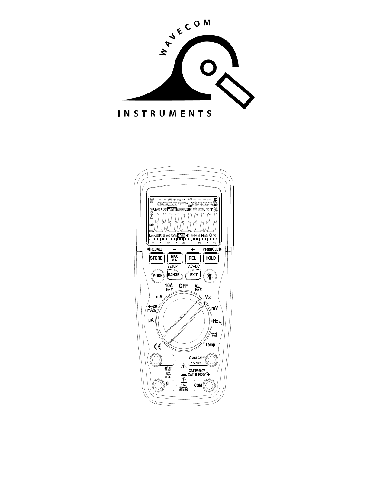
True RMS Industrial Multimeter
MODEL WAVECOM 98
Ω
10A
mA
A
Wavecom Instruments Pty Ltd
257 Grange Road FINDON SA 5023
P: (+61) 08 8243 3500 | F: (+61) 08 8243 3501
sales@wavecom.com.au | www.wavecom.com.au
Page 2

2
Page 3
3
Introduction
This meter measures AC/DC Voltage, AC/DC Current, Resistance, Capacitance, Frequency
(electrical & electronic), Duty Cycle, Diode Test, and Continuity plus Thermocouple Temperature.
It can store and recall data. It features a waterproof, rugged design for heavy duty use. This
meter can send out data wirelessly and be linked to PC. Proper use and care of this meter will
provide many years of reliable service.
Safety
This symbol adjacent to another symbol, terminal or operating device indicates that
the operator must refer to an explanation in the Operating Instructions to avoid
personal injury or damage to the meter.
This WARNING symbol indicates a potentially hazardous situation, which if not
avoided, could result in death or serious injury.
This CAUTION symbol indicates a potentially hazardous situation, which if not
avoided, may result damage to the product.
This symbol advises the user that the terminal(s) so marked must not be connected
to a circuit point at which the voltage with respect to earth ground exceeds (in this
case) 1000 VAC or VDC.
This symbol adjacent to one or more terminals identifies them as being associated
with ranges that may, in normal use, be subjected to particularly hazardous
voltages. For maximum safety, the meter and its test leads should not be handled
when these terminals are energized.
This symbol indicates that a device is protected throughout by double insulation or
reinforced insulation.
PER IEC1010 OVERVOLTAGE INSTALLATION CATEGORY
OVERVOLTAGE CATEGORY I
Equipment of OVERVOLTAGE CATEGORY I is equipment for connection to circuits in which
measures are taken to limit the transient overvoltages to an appropriate low level.
Note – Examples include protected electronic circuits.
OVERVOLTAGE CATEGORY II
Equipment of OVERVOLTAGE CATEGORY II is energy-consuming equipment to be supplied
from the fixed installation.
Note – Examples include household, office, and laboratory appliances.
OVERVOLTAGE CATEGORY III
Equipment of OVERVOLTAGE CATEGORY III is equipment in fixed installations.
Note – Examples include switches in the fixed installation and some equipment for industrial use
with permanent connection to the fixed installation.
OVERVOLTAGE CATEGORY IV
Equipment of OVERVOLTAGE CATEGORY IV is for use at the origin of the installation.
Note – Examples include electricity meters and primary over-current protection equipment
WARNING
CAUTION
MAX
1000V
Page 4
4
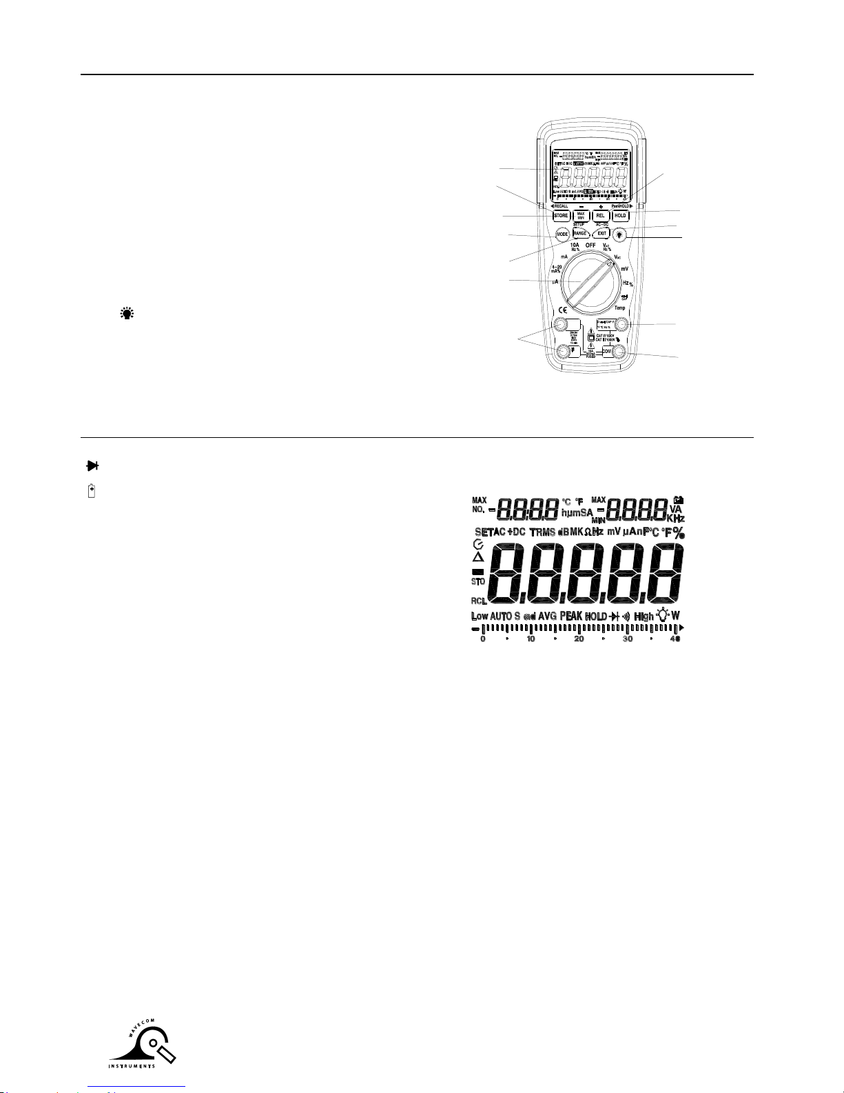
Controls and Jacks
1. 40,000 count LCD display
2. STORE(<RECALL) button
3. MAX/MIN (_)button
4. MODE button
5. RANGE(SETUP) button
6. Function switch
7. mA, µA and 10A input jacks
8. COM input jack
9. Positive input jack
10. Backlight button
11. EXIT(AC+DC) button
12. HOLD(PEAKHOLD>) button
13. REL(+) button
Note: Tilt stand and battery compartment are on rear of unit.
Symbols and Annunciators
•))) Continuity
Diode test
Battery status
n nano (10-9) (capacitance)
µ micro (10-6) (amps, cap)
m milli (10-3) (volts, amps)
A Amps
k kilo (103) (ohms)
F Farads (capacitance)
M mega (106) (ohms)
Ohms PEAK Peak Hold
Hz Hertz (frequency) V Volts
% Percent (duty ratio) REL Relative
AC Alternating current AUTO Auto ranging
DC Direct current HOLD Display hold
ºF Degrees Fahrenheit ºC Degrees Centigrade
MAX Maximum MIN Minimum
N0. Serial number
S second
left auxiliary display
right auxiliary display
SET Setup parameter
AC +DC Alternating current + Direct current
TRMS True RMS
STO Store
RCL Recall
AUTO Auto Range
Timing symbol
Backlight
bargraph
Ω
10A
mA
A
1
2
3
4
5
6
7
8
9
10
11
12
13
Page 5
5
Operating Instructions
WARNING: Risk of electrocution. High-voltage circuits, both AC and DC, are very dangerous
and should be measured with great care.
1. ALWAYS turn the function switch to the OFF position when the meter is not in use.
2. If “OL” appears in the display during a measurement, the value exceeds the range you have
selected. Change to a higher range.
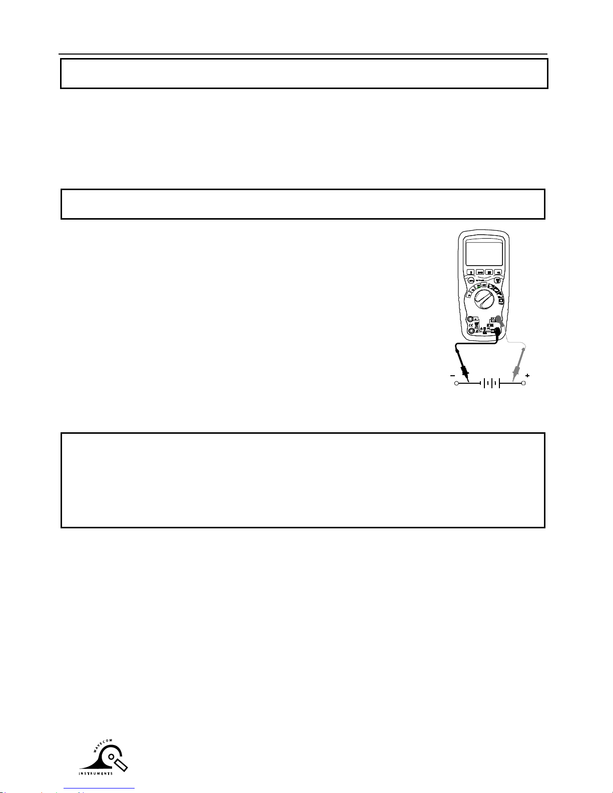
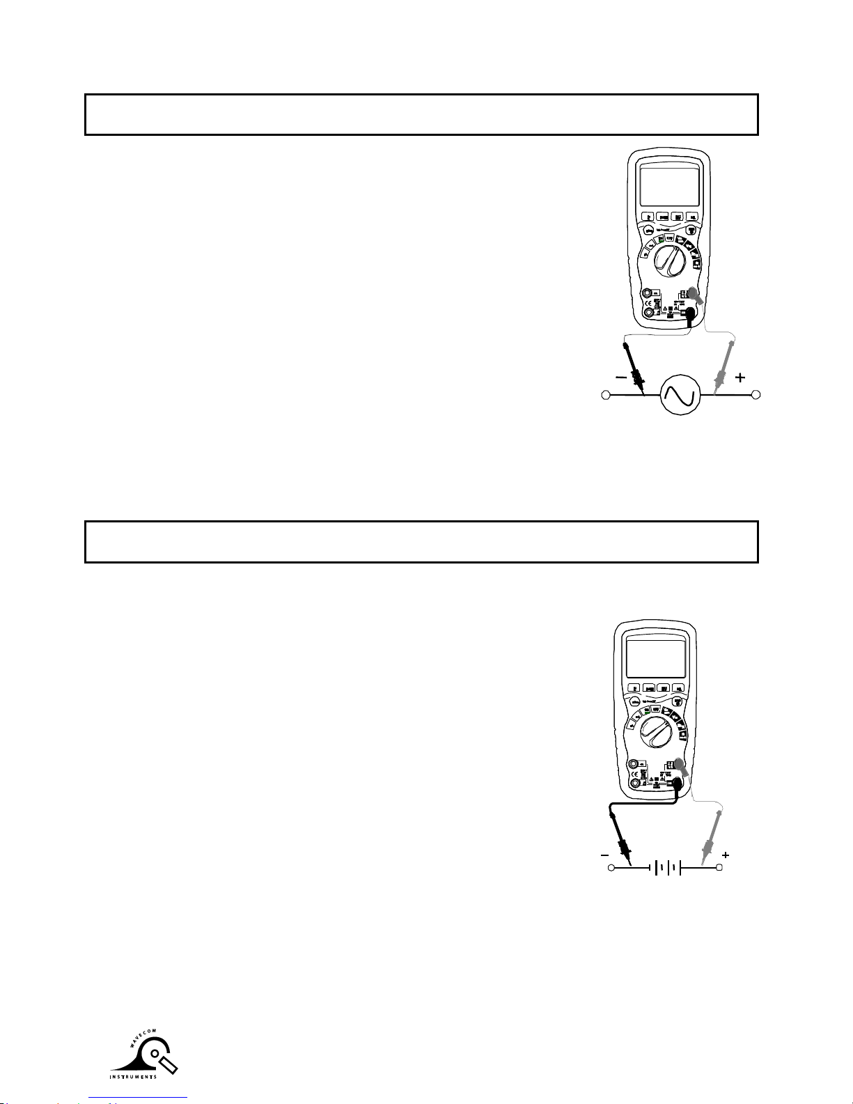
DC VOLTAGE MEASUREMENTS
CAUTION: Do not measure DC voltages if a motor on the circuit is being switched ON or
OFF. Large voltage surges may occur that can damage the meter.
1. Set the function switch to the VDC position.
2. Insert the black test lead banana plug into the negative COM jack.
Insert the red test lead banana plug into the positive V jack.
3. Touch the black test probe tip to the negative side of the circuit.
Touch the red test probe tip to the positive side of the circuit.
4. Read the voltage in the display.
AC VOLTAGE (FREQUENCY, DUTY CYCLE) MEASUREMENTS
WARNING: Risk of Electrocution. The probe tips may not be long enough to contact the live
parts inside some 240V outlets for appliances because the contacts are recessed deep in the
outlets. As a result, the reading may show 0 volts when the outlet actually has voltage on it.
Make sure the probe tips are touching the metal contacts inside the outlet before assuming
that no voltage is present.
Also make sure that the test lead banana plugs are firmly inserted into banana jack and Meter
responsive
Page 6
6
CAUTION: Do not measure AC voltages if a motor on the circuit is being switched ON or
OFF. Large voltage surges may occur that can damage the meter.
1. Set the function switch to the VAC/Hz/% position.
2. Insert the black test lead banana plug into the negative COM jack.
Insert red test lead banana plug into the positive V jack.
3. Touch the black test probe tip to the neutral side of the circuit.
Touch the red test probe tip to the “hot” side of the circuit.
4. Read the voltage in the main display and the frequency in the right
auxiliary display
5. Press the MODE button to indicate “Hz ”.
6. Read the frequency in the main display.
7. Press the MODE button again to indicate “%”.
8. Read the % of duty cycle in the main display.
9. Press EXIT for 2 seconds into the function of AC+DC. Test DC and
AC TRUE Rms.
mV VOLTAGE MEASUREMENTS
CAUTION: Do not measure mV voltages if a motor on the circuit is being switched ON or
OFF. Large voltage surges may occur that can damage the meter.
1. Set the function switch to the mV position.
2. Press the MODE button to indicate “DC”. Or ““AC ”, or in AC range press EXIT for two
seconds and chose ”AC+DC”
3. Insert the black test lead banana plug into the negative COM jack.
Insert the red test lead banana plug into the positive V jack.
4. Touch the black test probe tip to the negative side of the circuit.
Touch the red test probe tip to the positive side of the circuit.
5. Read the mV voltage in the main display.
Page 7
7
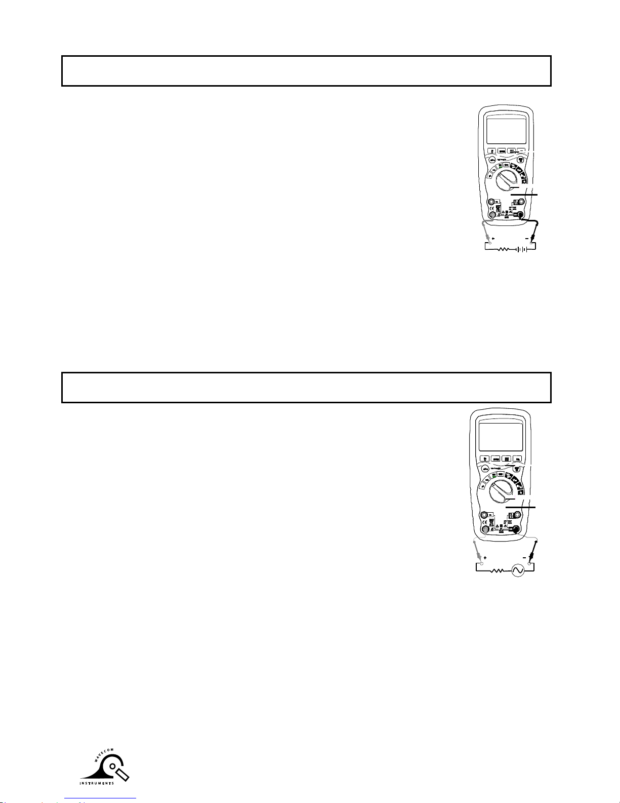
DC CURRENT MEASUREMENTS
CAUTION: Do not make 20A current measurements for longer than 30 seconds. Exceeding
30 seconds may cause damage to the meter and/or the test leads.
1. Insert the black test lead banana plug into the negative COM jack.
2. For current measurements up to 4000µA DC, set the function switch to the
yellow µA position and insert the red test lead banana plug into the µA/mA
jack.
3. For current measurements up to 400mA DC, set the function switch to the
yellow mA position and insert the red test lead banana plug into the µA/mA
jack.
4. For current measurements up to 20A DC, set the function switch to the
yellow 10A/HZ/% position and insert the red test lead banana plug into the
10A jack.
5. Press the MODE button to indicate “DC” on the display.
6. Remove power from the circuit under test, then open up the circuit at the
point where you wish to measure current.
7. Touch the black test probe tip to the negative side of the circuit.
Touch the red test probe tip to the positive side of the circuit.
8. Apply power to the circuit.
9. Read the current in the display.
AC CURRENT (FREQUENCY, DUTY CYCLE) MEASUREMENTS
CAUTION: Do not make 20A current measurements for longer than 30 seconds. Exceeding
30 seconds may cause damage to the meter and/or the test leads.
1. Insert the black test lead banana plug into the negative COM jack.
2. For current measurements up to 4000µA AC, set the function switch to
the yellow µA position and insert the red test lead banana plug into the
µA/mA jack.
3. For current measurements up to 400mA AC, set the function switch to
the yellow mA position and insert the red test lead banana plug into the
µA/mA jack.
4. For current measurements up to 20A AC, set the function switch to the
yellow 10A/HZ/% position and insert the red test lead banana plug into
the 10A jack.
5. Press the MODE button to indicate “AC” on the display.
6. Remove power from the circuit under test, then open up the circuit at the
point where you wish to measure current.
7. Touch the black test probe tip to the neutral side of the circuit.
Touch the red test probe tip to the “hot” side of the circuit.
8. Apply power to the circuit.
9. Read the current in the display. In the 10A AC range, right auxiliary display frequency.
10. Press and hold the MODE button to indicate “Hz ”.
11. Read the frequency in the display.
12. Momentarily press the MODE button again to indicate “%”.
13. Read the % duty cycle in the display.
14. Press and hold the MODE button to return to current measurement.
15. Press EXIT for 2 seconds into the function of AC+DC. Test DC and AC TRUE Rms.
Page 8

8
RESISTANCE MEASUREMENTS
WARNING: To avoid electric shock, disconnect power to the unit under test and discharge all
capacitors before taking any resistance measurements. Remove the batteries and unplug the
line cords.
1. Set the function switch to the ΩCAPposition.
2. Insert the black test lead banana plug into the negative COM jack.
Insert the red test lead banana plug into the positive jack.
3. Press the MODE button to indicate “ ”on the display.
4. Touch the test probe tips across the circuit or part under test. It is best
to disconnect one side of the part under test so the rest of the circuit
will not interfere with the resistance reading.
5. Read the resistance in the display.
CONTINUITY CHECK
WARNING: To avoid electric shock, never measure continuity on circuits or wires that have
voltage on them.
1. Set the function switch to the Ω CAP position.
2. Insert the black lead banana plug into the negative COM jack.
Insert the red test lead banana plug into the positive jack.
3. Press the MODE button to indicate“ " and “Ω” on the display
4. Touch the test probe tips to the circuit or wire you wish to check.
5. If the resistance is less than approximately 35, the audible signal
will sound. If the circuit is open, the display will indicate “OL”.
Page 9
9
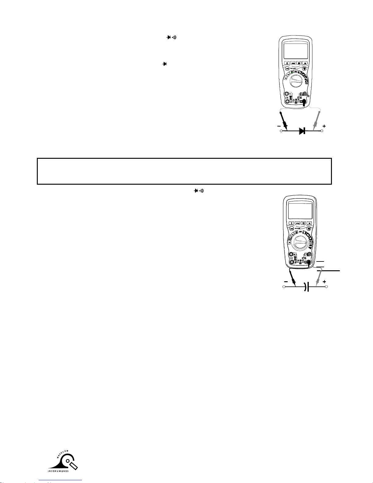
DIODE TEST
1. Set the function switch to the Ω CAP position.
2. Insert the black test lead banana plug into the negative COM jack and
the red test lead banana plug into the positive V jack.
3. Press the MODE button to indicate “ “and “V” on the display.
4. Touch the test probes to the diode under test. Forward voltage will
typically indicate 0.400 to 0.700V. Reverse voltage will indicate “OL”.
Shorted devices will indicate near 0V and an open device will indicate
“OL” in both polarities.
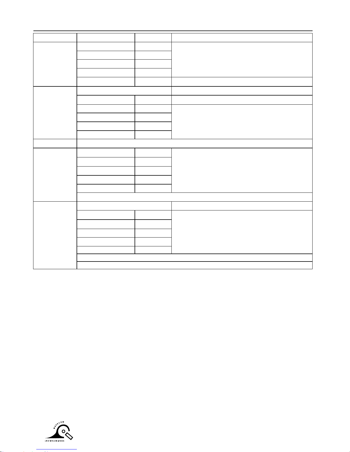
CAPACITANCE MEASUREMENTS
WARNING: To avoid electric shock, disconnect power to the unit under test and discharge all
capacitors before taking any capacitance measurements. Remove the batteries and unplug
the line cords.
1. Set the rotary function switch to the Ω CAP position.
2. Insert the black test lead banana plug into the negative COM jack.
3. Insert the red test lead banana plug into the positive V jack.
4. Press the MODE button to indicate “F”
5. Touch the test leads to the capacitor to be tested.
6. Read the capacitance value in the display
Page 10

10
TEMPERATURE MEASUREMENTS
1. Set the function switch to the Temp position.
2. Insert the Temperature Probe into the input jacks, making sure
to observe the correct polarity.
3. Press the MODE button to indicate “ºF” or “ºC”
4. Touch the Temperature Probe head to the part whose temperature
you wish to measure. Keep the probe touching the part under test
until the reading stabilizes (about 30 seconds).
5. Read the temperature in the display.
Note: The temperature probe is fitted with a type K mini connector.
A mini connector to banana connector adaptor is supplied for
connection to the input banana jacks.
FREQUENCY (DUTY CYCLE) MEASUREMENTS (ELECTRONIC)
1. Set the rotary function switch to the Hz/% position.
2. Insert the black lead banana plug into the negative COM jack and
the red test lead banana plug into the positive Hz jack.
3. Touch the test probe tips to the circuit under test.
4. Read the frequency on the display.
5. Press the MODE button to indicate “%”.
6. Read the % duty cycle in the display.
Page 11

11
4 – 20mA % MEASUREMENTS
1. Set up and connect as described for DC mA measurements.
2. Set the rotary function switch to the 4-20mA% position.
3. The meter will display loop current as a % with 0mA=-25%, 4mA=0%, 20mA=100%, and
24mA=125%.
AUTORANGING/MANUAL RANGE SELECTION
When the meter is first turned on, it automatically goes into Auto Ranging. This automatically
selects the best range for the measurements being made and is generally the best mode for
most measurements. For measurement situations requiring that a range be manually selected,
perform the following:
1. Press the RANGE key. The “AUTO” display indicator will turn off.
2. Press the RANGE key to step through the available ranges until you select the range you
want.
3. To exit the Manual Ranging mode and return to Auto ranging, press EXIT
Note: Manual ranging does not apply for the Temperature functions.
MAX/MIN
1. Press the MAX/MIN key to activate the MAX/MIN recording mode. The display icon "MAX"
will appear. The meter left auxiliary display will display and hold the maximum reading and
will update only when a new “max” occurs. The display icon "MIN" will appear. The right
auxiliary display meter will display and hold the minimum reading and will update only when
a new “min” occurs.
2. To exit MAX/MIN mode press EXIT
RELATIVE MODE
The relative measurement feature allows you to make measurements relative to a stored
reference value. A reference voltage, current, etc. can be stored and measurements made in
comparison to that value. The displayed value is the difference between the reference value
and the measured value. Note: Relative mode does not operate in the 4-20mA function.
1. Perform the measurement as described in the operating instructions.
2. Press the REL button to store the reading in the display and the "REL" indicator will
appear on the display.
3. Left auxiliary display will display the margin of initial value and the current value.
Right auxiliary display will display the initial reading. Main display the reading after
REL TEST.
4. Press the EXIT button to exit the relative mode.
Page 12

12
DISPLAY BACKLIGHT
Press the key to turn the backlight on. The backlight will automatically turn off after
SET time. Press the EXIT button to exit the backlight on mode.
HOLD
The hold function freezes the reading in the display. Press the
HOLD
key momentarily to
activate or to exit the
HOLD
function.
PEAK HOLD
The Peak Hold function captures the peak AC or DC voltage or current. The meter can capture
negative or positive peaks as fast as 1 millisecond in duration. Momentarily press the PEAK
button, “PEAK” and “MAX” will display in left auxiliary display. MIN” will display in right
auxiliary display. The meter will update the dispay each time a lower negative peak occurs.
Press the EXIT button to exit the PEAK HOLD mode. Auto Power Off feature will be disabled
automatically in this mode.
Data record(STORE/RECALL )
1. STORE function
In the current testing mode, press STORE button one time, enter into STORE function.
On the left upper corner of LCD shows NO XXXX.,
which states current storage serial number. Then, press button PEAKHOLD to change into the
initial serial number 0000. (Press again it will change back).
On the right upper corner of LCD shows XXXX ,which states how many current storage
values are used.
Press STORE button again, enter into recording interval time set up function.
On the left upper shows 0000 S ,which states recording interval time; using button + & -
to select,the range is 0~255 seconds。
When the recording interval time is 0000 S,then press STORE button again to change into
manual recording. Press the STORE button again to record once.
When the recording interval time is 1~255 S,
then press STORE button again to start recording
automatically from 0000.
Recording times is showed on the left upper corner, data is showed on the right upper corner
(Due to digital limitation, there is only four preceding numbers displayed)
To finish above STORE function, press EXIT button shortly.
If you expect to clear all memory data:
While power on, hold EXIT button, and switch from OFF to random and then release EXIT butt
on, the LCD will flash thrice and buzzer thrice too, which means all memory data is cleared.
Page 13

13
2. RECALL function
Press STORE button two seconds to enter into RECALL function.
On the left upper corner shows XXXX, which states current storage serial number.
On the right upper corner shows XXXX, which states how many current storage is used.
Press button PEAKHOLD shortly once to scan data from 0000 to XXXX continuously.
Press again then scan again.
Use button + & - to select serial number XXXX on the left upper corner and record data on the
right upper corner.
To finish above RECALL function, press EXIT button.
WIRELESS DATA SENDING FUNCTION:
1. Install and launch the PC software
2. Explore the CD, read the USB Driver Installation documentation and choose the appropriat
e driver for your PC Operating System.
3. Connect the USB Wireless Receiver to your PC.
4. Double click the multimeter icon or access from the Start menu on your PC and open
the operating interface.
5. When ready, hold WAVECOM 98 backlit for 2 secs, entering into wireless sending state.
The RF icon will flash on the upper right of LCD. When the wireless receiver, receives the
signal, it will flash and meanwhile the wireless receiver indicates and the light will flash
synchronously.
6. Setting up COM input of PC,
press link button to ON, on WAVECOM 98 operating interface will show tested parameter
data synchronously and record in the PC.
On the PC operating interface you may set up a start time and interval between each
recording.
The Meter may operate at a distance from Wireless receiver up to about 10M.
Page 14

14
Parameter setting up(SET)
1. Press the RANGE button second seconds to enter into SET function. Then press shortly
once, change on setting content.
Setting content includes (in sequence) :
A: upper limit buzzer alarm
B: lower limit buzzer alarm
C: auto power off time
D: turn off phonating
E: back lit time
Use ←, +, -, → buttons to select the parameter
2. Press SET button continuously to switch to setting content, till exiting set up to testing
mode. So the updated setting content is saved. If press EXIT button in this period, all
setting can’t be saved.
AC+DC
In all the measuring mode VAC, mV (AC), 10A (AC), mA (AC), auk (AC), press button EXIT f
or 2seconds to enters into AC+DC testing. The precision is the same as AC measure. LCD
shows AC+DC signal. Press button EXIT to exit.
LOW BATTERY INDICATION
When the icon appears alone in the display, the battery should be replaced.
Page 15

15
Maintenance
WARNING: To avoid electric shock, disconnect the test leads from any source of voltage
before removing the back cover or the battery or fuse covers.
WARNING: To avoid electric shock, do not operate your meter until the battery and fuse covers
are in place and fastened securely.
This MultiMeter is designed to provide years of dependable service, if the following care
instructions are performed:
1. KEEP THE METER DRY. If it gets wet, wipe it off.
2. USE AND STORE THE METER IN NORMAL TEMPERATURES. Temperature extremes
can shorten the life of the electronic parts and distort or melt plastic parts.
3. HANDLE THE METER GENTLY AND CAREFULLY. Dropping it can damage the
electronic parts or the case.
4. KEEP THE METER CLEAN. Wipe the case occasionally with a damp cloth. DO NOT use
chemicals, cleaning solvents, or detergents.
5. USE ONLY FRESH BATTERIES OF THE RECOMMENDED SIZE AND TYPE. Remove
old or weak batteries so they do not leak and damage the unit.
6. IF THE METER IS TO BE STORED FOR A LONG PERIOD OF TIME, the batteries should
be removed to prevent damage to the unit.
BATTERY INSTALLATION
WARNING: To avoid electric shock, disconnect the test leads from any source of voltage before
removing the battery cover.
1. Turn power off and disconnect the test leads from the meter.
2. Open the rear battery cover by removing two screws (B) using a Phillips head screwdriver.
3. Insert the battery into battery holder, observing the correct polarity.
4. Put the battery cover back in place. Secure with the screws.
WARNING: To avoid electric shock, do not operate the meter until the battery cover is in place
and fastened securely.
NOTE: If your meter does not work properly, check the fuses and batteries to make sure that
they are still good and that they are properly inserted.
Page 16

16
REPLACING THE FUSES
WARNING: To avoid electric shock, disconnect the test leads from any source of voltage
before removing the meter cover.
1. Disconnect the test leads from the meter.
2. Remove the protective rubber holster.
3. Remove the battery cover (two “B” screws) and the battery.
4. Remove the six “A” screws securing the rear cover.
5. Gently remove the old fuse and install the new fuse into the holder.
6. Always use a fuse of the proper size and value (0.5A/1000V fast blow for the 400mA
range [SIBA 70-172-40], 10A/1000V fast blow for the 20A range [SIBA 50-199-06]).
7. Replace and secure the rear cover, battery and battery cover.
WARNING: To avoid electric shock, do not operate your meter until the fuse cover is in place
and fastened securely.
Page 17
17
Specifications
Function
Range
Resolution
Accuracy
DC Voltage
400mV
0.01mV
(0.06% reading + 4digits)
4V
0.0001V
40V
0.001V
400V
0.01V
1000V
0.1V
(0.1% reading + 5digits)
AC Voltage
(AC+DC)
50 to 1000Hz
400mV
0.01mV
(1.0% reading + 40digits)
4V
0.0001V
(1.0% reading + 30 digits)
40V
0.001V
400V
0.01V
1000V
0.1V
All AC voltage ranges are specified from 5% of range to 100% of range
DC Current
400A
0.01A
(1.0% reading + 3 digits)
4000A
0.1A
40mA
0.001mA
400mA
0.01mA
10A
0.001A
(20A: 30 sec max with reduced accuracy)
AC Current
(AC+DC)
50 to 1000Hz
400A
0.01A
(1.5% reading + 30digits)
4000A
0.1A
40mA
0.001mA
400mA
0.01mA
10A
0.001A
(20A: 30 sec max with reduced accuracy)
All AC voltage ranges are specified from 5% of range to 100% of range
NOTE: Accuracy is stated at 65oF to 83oF (18oC to 28oC) and less than 75% RH.
AC switch according to the calibration of sine wave. It generally increase (2% reading + 2% full
scale) if non sine wave in the wave crest less than 3.0.
Page 18

18
Function
Range
Resolution
Accuracy
Resistance
400
0.01
(0.3% reading + 9 digits)
4k
0.0001k
(0.3% reading + 4 digits)
40k
0.001k
400k
0.01k
4M
0.001M
40M
0.001M
(2.0% reading + 10 digits)
Capacitance
40nF
0.001nF
(3.5% reading + 40 digits)
400nF
0.01nF
4F
0.0001F
(3.5% reading + 10 digits)
40F
0.001F
400F
0.01F
4000µF
0.1µF
(5% reading + 10 digits)
40mF
0.001mF
Frequency
(electronic)
40Hz
0.001Hz
(0.1% reading + 1 digits)
400Hz
0.01Hz
4kHz
0.0001kHz
40kHz
0.001kHz
400kHz
0.01kHz
4MHz
0.0001MHz
40MHz
0.001MHz
100MHz
0.01MHz
Not specified
Sensitivity: 0.8V rms min. @ 20% to 80% duty cycle and <100kHz; 5Vrms min
@ 20% to 80% duty cycle and > 100kHz.
Frequency
(electrical)
40.00HZ10KHz
0. 01HZ—
0.001KHz
(0.5% reading)
Sensitivity:1Vrms
Duty Cycle
0.1 to 99.90%
0.01%
(1.2% reading + 2 digits)
Pulse width: 100µs - 100ms, Frequency: 5Hz to 150kHz
Temp
(type-K)
-58 to 2192F
0.1F
(1.0% reading + 4.5°F)
(1.0% reading + 2.5°C)
(probe accuracy not included)
-50 to 1200C
0.1C
4-20mA%
-25 to 125%
0.01%
±50 digits
0mA=-25%, 4mA=0%, 20mA=100%, 24mA=125%
Note: Accuracy specifications consist of two elements:
(% reading) – This is the accuracy of the measurement circuit.
(+ digits) – This is the accuracy of the analog to digital converter.
Page 19

19
Store capacitance 9999
Enclosure Double molded, waterproof
Shock (Drop Test) 6.5 feet (2 meters)
Diode Test Test current of 0.9mA maximum, open circuit voltage 2.8V DC typical
Continuity Check Audible signal will sound if the resistance is less than 35 (approx.),
test current <0.35mA
PEAK Captures peaks >1ms
Temperature Sensor Requires type K thermocouple
Input Impedance >10MΩ VDC & >9MΩ VAC
AC Response True rms
AC True RMS: The term stands for “Root-Mean-Square,” which represents the
method of calculation of the voltage or current value. Average
responding multimeters are calibrated to read correctly only on sine
waves and they will read inaccurately on non-sine wave or distorted
signals. True rms meters read accurately on either type of signal.
ACV Bandwidth 50Hz to 1000Hz
Crest Factor ≤3 at full scale up to 500V, decreasing linearly to ≤1.5 at 1000V
Display 40,000 count backlit liquid crystal with bargraph
Over range indication “OL” is displayed
Auto Power Off 15 minutes (approximately) with disable feature
Polarity Automatic (no indication for positive); Minus (-) sign for negative
Measurement Rate 2 times per second, nominal
Low Battery Indication “ ” is displayed if battery voltage drops below operating voltage
Battery One 9 volt (NEDA 1604) battery
Fuses mA, µA ranges; 0.5A/1000V ceramic fast blow
A range; 10A/1000V ceramic fast blow
Operating Temperature 41ºF to 104ºF (5ºC to 40ºC)
Storage Temperature -4oF to 140oF (-20oC to 60oC)
Operating Humidity Max 80% up to 87ºF (31ºC) decreasing linearly to 50% at 104ºF
(40ºC)
Storage Humidity <80%
Operating Altitude 7000ft. (2000meters) maximum.
Weight 0.753lb (342g) (includes holster).
Size 7.36” x 3.2” x 2.0” (187 x 81 x 50mm) (includes holster)
Safety This meter is intended for origin of installation use and protected,
against the users, by double insulation per EN61010-1 and IEC610101 2nd Edition (2001) to Category IV 600V and Category III 1000V;
Pollution Degree 2. The meter also meets UL 61010-1, 2nd Edition
(2004), CAN/CSA C22.2 No. 61010-1 2nd Edition (2004), and UL
61010B-2-031, 1st Edition (2003)
Page 20

20
Wavecom Instruments Pty Ltd
Adelaide
257 Grange Road
FINDON SA 5023
Ph: (+61) 08 8243 3500
Fax: (+61) 08 8243 3501
Email: sales@wavecom.com.au
Web: www.wavecom.com.au
Melbourne
772A Station Street
BOX HILL VIC 3128
Ph: (+61) 03 9897 4711
Fax: (+61) 03 9897 4766
Email: salesvic@wavecom.com.au
Web: www.wavecom.com.au
 Loading...