

Page 1
ALLEGRETTO WAVE EYE-Q
User Manual
Page 2

This User Manual ALLEGRETTO WAVE EYE-Q is valid as from Firmware Version PRV4-1.02 (see chapter
Software Version 2.020 (see chapter
5.3 “Turning On The System” from page 37) and Notebook Portal
5.6.19 “Notebook Software Info” on page 127).
Page 2 of 232 ALLEGRETTO WAVE EYE-Q 1010 User Manual en / Rev.9 / 09-06-08 Item No.: 6638 2001
Page 3
Typographical Conventions
TYPOGRAPHICAL CONVENTIONS
The following conventions and symbols are used in this manual:
A Warning alerts the user to potential serious outcomes to the patient or user
in case of non observance of this warning.
Precautions alert the reader to exercise special care necessary for the safe
and effective use of the device.
Notes provide helpful or supplementary information to the user.
Further Typographical Conventions:
In addition to the aforementioned, the following conventions are used in this User
Manual.
KEYBOARD Here you have to enter or edit items in the menu.
MOUSE Move mouse or click mouse button.
WARNING
CAUTION
NOTE
ALLEGRETTO WAVE EYE-Q 1010 User Manual en / Rev.9 / 09-06-08 Item No.: 6638 2001 Page 3 of 232
Page 4
General Warnings And Precautions
GENERAL WARNINGS AND PRECAUTIONS
This laser workstation and its accessories can cause flammable materials to
ignite or explode.
Use of controls or adjustments or performance of procedures other than those
specified herein may result in hazardous radiation exposure.
This manual is copyrighted with all rights reserved. Under copyright laws this manual may not be reproduced
or transmitted in whole or in part in any form or by any means, electronic or mechanical, including
photocopying, recording, or any information storage and retrieval system, without permission i n writing from
WaveLight AG.
Permitted copies must carry the same proprietary and copyright notices as were affixed to the original.
Under the law, copying includes also translation into other languages.
Please note that while every effort has been made to ensure that the data give n in this manual are accurate,
the information, figures, illustration, tables, specifications and schematics contained herein are subject to
change without notice.
All images are representative. The numbers shown in the images are just examples and may not represent
typical values. Some sections of this manual may not apply for all devices. Such sections will be marked
accordingly. Other manuals may apply as well for use of the device described herein.
ALLEGRETTO WAVE
Wavefront Optimized™ is a registered trademark of WaveLight AG.
Custom Q® is a registered trademark of WaveLight AG.
PerfectPulse Technology
Right.From the Start.
Zeiss and OPMI are registered trademarks of Carl Zeiss.
Microsoft, Windows™ 2000 is a registered trademark of Microsoft Corporation.
®
EYE-Q is a registered trademark of WaveLight AG.
®
is a registered trademark of WaveLight AG.
®
is a registered trademark of WaveLight AG.
© Copyright by WaveLight AG, Germany
All Rights reserved
WARNING
CAUTION
Page 4 of 232 ALLEGRETTO WAVE EYE-Q 1010 User Manual en / Rev.9 / 09-06-08 Item No.: 6638 2001
Page 5

Contents
CONTENTS
1. INTRODUCTION...............................................................................................11
Page
2. GENERAL NOTICES TO USERS ....................................................................
12
3. SAFETY INSTRUCTIONS................................................................................13
3.1. Eye Protection....................................................................................15
3.2. Safety Against Fluorine and Ozone....................................................16
3.3. Patient Safety.....................................................................................17
3.4. Use Restrictions.................................................................................19
3.5. Safety Design.....................................................................................22
4. SYSTEM DESCRIPTION..................................................................................23
4.1. System Overview ...............................................................................23
4.2. Lighting...............................................................................................24
4.3. Switching Elements And Interfaces....................................................
5. FUNCTIONAL DESCRIPTION .........................................................................
25
35
5.1. Important Steps Before Turning On The System................................35
5.2. Structure Of The ALLEGRETTO WAVE EYE-Q Firmware.................36
5.3. Turning On The System .....................................................................37
5.3.1. Logfile Option.....................................................................................38
5.3.2. Self Test.............................................................................................41
ALLEGRETTO WAVE EYE-Q 1010 User Manual en / Rev.9 / 09-06-08 Item No.: 6638 2001 Page 5 of 232
Page 6

5.4. System Check ....................................................................................42
5.4.1. General Information About The System Check ..................................42
5.4.2. Check Of Nitrogen-Gas Pressure And Beam Path Flushing ..............43
5.4.3. ArF-Premix-Gas Pressure..................................................................45
5.4.4. Laser Head Pressure..........................................................................47
5.4.5. Check And Calibration Of The Internal Laser Energy.........................50
5.4.6. Eyetracker Test ..................................................................................61
5.4.7. Fluence Test.......................................................................................62
Contents
Page
5.5. Treatment Direct Entry Without Notebook..........................................63
5.5.1. Nomogram..........................................................................................64
5.5.2. Entering Treatment Data....................................................................65
5.6. Navigation And Data Entry With The Notebook Portal Software........
5.6.1. Starting The Notebook Program.........................................................
69
71
5.6.2. How To Perform A Wavefront Optimized Treatment ..........................72
5.6.3. Examination Data Range Wavefront Optimized.................................92
5.6.4. Treatment Data Range Wavefront Optimized.....................................93
5.6.5. Printout...............................................................................................94
5.6.6. Screenshot.........................................................................................95
Page 6 of 232 ALLEGRETTO WAVE EYE-Q 1010 User Manual en / Rev.9 / 09-06-08 Item No.: 6638 2001
Page 7

Contents
5.6.7. How To Perform a PTK Treatment.....................................................96
5.6.8. Treatment Data Range PTK.............................................................109
5.6.9. Import Data.......................................................................................110
5.6.10. Setting Menu....................................................................................118
5.6.11. How To Change The Language And The Date/Time Format...........119
5.6.12. How to Set The Timer ......................................................................120
5.6.13. Enter Default Settings ......................................................................121
5.6.14. Treatment Counter...........................................................................123
Page
5.6.15. Connect To Service Center..............................................................126
5.6.16. Browse Customer Info......................................................................126
5.6.17. Recreate Data-Files .........................................................................126
5.6.18. Service .............................................................................................
5.6.19. Notebook Software Info....................................................................
127
127
5.6.20. Shutdown The Program ...................................................................128
5.7. Positioning The Patient ....................................................................129
5.8. Checking The Eyetracker Function .................................................. 130
5.9. Hints For Keratectomy......................................................................132
5.10. Ready Mode.....................................................................................133
ALLEGRETTO WAVE EYE-Q 1010 User Manual en / Rev.9 / 09-06-08 Item No.: 6638 2001 Page 7 of 232
Page 8

5.11. Patient’s Eye Alignment, Fixation And Centering.............................134
5.12. Starting Laser Treatment..................................................................136
5.13. Interrupting Treatment......................................................................138
5.14. Aborting Treatment...........................................................................139
5.15. Finishing Treatment..........................................................................139
5.16. Setup Menu......................................................................................140
5.16.1. General Settings “Next Page”...........................................................142
5.16.2. Fluence Test.....................................................................................143
Contents
Page
5.16.3. ET-Test.............................................................................................143
5.16.4. Gas Change ArF...............................................................................144
5.16.5. Scanner Test....................................................................................144
5.16.6. Micrometer Test................................................................................
5.16.7. External Energy Check.....................................................................
144
144
5.16.8. Definition Center Of Ablation............................................................145
5.16.9. LCD Contrast....................................................................................148
5.16.10. Brightness Setting Distance Diodes .................................................149
5.16.11. Brightness Setting Aiming Beam......................................................150
5.16.12. Vertex Distance................................................................................151
5.16.13. Setting Flat K....................................................................................151
Page 8 of 232 ALLEGRETTO WAVE EYE-Q 1010 User Manual en / Rev.9 / 09-06-08 Item No.: 6638 2001
Page 9

Contents
5.17. Routine Test Procedures With The Control Systems.......................152
5.17.1. The Calibration Tool Kit....................................................................154
5.17.2. Check Of The Eyetracker Function ..................................................155
5.17.3. Eyetracker Test And Calibration Procedure .....................................156
5.17.4. Test Of Eyetracker Centering...........................................................164
5.17.5. Fluence Test And Calibration Procedure ..........................................165
5.17.6. Ablation Depth Normal Glass Standard............................................177
5.17.7. Scanner Test....................................................................................180
Page
5.17.8. Scanner Test Procedure .................................................................. 180
5.18. Turning Off .......................................................................................184
6. ACCESSORIES..............................................................................................186
6.1. Patient Bed .......................................................................................
6.2. Video Adapter...................................................................................
187
187
6.3. Notebook..........................................................................................187
7. CARE OF DEVICE AND ACCESSORIES......................................................188
8. ERRORS AND HOW TO FIX ..........................................................................189
9. LIST OF MESSAGES AND WARNINGS ....................................................... 198
ALLEGRETTO WAVE EYE-Q 1010 User Manual en / Rev.9 / 09-06-08 Item No.: 6638 2001 Page 9 of 232
Page 10

Contents
Page
10. TECHNICAL ASSISTANCE ...........................................................................210
10.1. Service Hotline .................................................................................210
10.2. Maintenance.....................................................................................211
10.3. Technical Safety Inspection..............................................................212
10.4. Disposal............................................................................................213
11. LABELING......................................................................................................214
11.1. Labeling Of The Laser Unit...............................................................214
11.2. Labeling Of The Ablation Depth Micrometer.....................................219
11.3. Labeling Of The Test Adapter ..........................................................220
11.4. Labeling Of The Laser Area .............................................................221
12. TECHNICAL DATA.........................................................................................222
12.1. Device Data......................................................................................222
12.2. Electromagnetic Compatibility ..........................................................
13. WARRANTY ...................................................................................................
14. LIST OF ACCESSORY PRODUCTS ..............................................................
225
230
231
Page 10 of 232 ALLEGRETTO WAVE EYE-Q 1010 User Manual en / Rev.9 / 09-06-08 Item No.: 6638 2001
Page 11

Introduction
1. INTRODUCTION
Intended Use:
The ALLEGRETTO WAVE EYE-Q is a scanning-spot excimer laser system used in
refractive surgery for LASIK (Laser In-Situ Keratomileusis) treatments.
The uniqueness of the system consists in a combination of technologically refined
features, including a compact excimer laser with leading edge high pulse frequency, a
galvanometer scanner for positioning the laser spot and a fast eyetracker for determining
eye position and laser-beam direction. The Gaussian-shaped beam profile of the
individual pulses and an ablation diameter of approximately 1 mm assure the desired
contour and minimize surface irregularities during ablation.
In addition to the photorefractive Wavefront Optimized applications (myopia with or
without astigmatism, hyperopia with or without astigmatism), this attribute in combination
with the open system concept enables also the usage of patient related, individual
corrections. These corrections could e.g. be based on topography or wavefront data.
A further advantage of the small spot diameter is that the ALLEGRETTO WAVE EYE-Q
requires the use of only minimal pulse energy. The result is a compact excimer laser
beam source with minimal gas volume and minimal gas consumption. As the excimer
laser is operated at a high repetition frequency, short treatment times are assured. The
integrated eyetracker offers unique automatic centering of the ablation and tracking of
even rapid eye movements. With the ALLEGRETTO WAVE EYE-Q the user is provided
with a medical device featuring maximum control and safety thus offering the patient
highest customer satisfaction.
If you have any questions, please call:
Am Wolfsmantel 5
91058 Erlangen, Germany
Hotline
Tel: + 49 1805 / 52 62 62
Fax: + 49 9131 / 6186 -221
E-Mail Service: ophtha-service@wavelight.com
E-Mail Application: ophtha-applications@wavelight.com
ALLEGRETTO WAVE EYE-Q 1010 User Manual en / Rev.9 / 09-06-08 Item No.: 6638 2001 Page 11 of 232
Page 12
General Notices To Users
2. GENERAL NOTICES TO USERS
As with every technologically sophisticated medical device, the use of this
laser system requires special training and skills. The laser may only be used
by specially trained physicians who are well versed in its therapeutic effects
and possible dangers and who possess the necessary skills to use it in
conformity with the operating instructions contained in this User Manual.
The ALLEGRETTO WAVE EYE-Q laser is a medical device currently designed for use
according to its intended use as described in this User Manual. Applications other than
those described in this User Manual are prohibited and are the exclusive responsibility of
the operator.
CAUTION
This User Manual refers only to operation, maintenance and care of the device.
All treatment data in the figures are given as example values.
In this User Manual modifications are described which are valid for firmware version
PR-V4-1.02 and notebook software version 2.020 or later.
The use of mobile telephones or similar appliances is not allowed while the
device is working.
On account of the possible risk of interference from electromagnetic radiation
while the ALLEGRETTO WAVE EYE-Q laser system is in operation, persons
with heart pacemakers may not be present in the room.
The effect of electromagnetic radiation of the device on embryos or pregnant women has
not been specifically studied. However, the device fulfils the international
electromagnetic safety standard DIN EN 60601-1-2. Local laws and regulations beyond
this safety standard in regards to pregnant women in the vicinity of the device during
start-up, stand-by or operation must be followed.
Should the laser system or any accessory require service, please do not attempt to
perform service yourself. Only WaveLight AG authorized service technicians or service
technicians who have been specifically authorized by WaveLight AG are allowed to
service the ALLEGRETTO WAVE EYE-Q laser system. Servicing or any kind of
manipulation of the system, by non-authorized personnel will result in a termination of
the warranty and a nullification of any liability on the part of WaveLight AG.
There exist no rightful claims to system upgrades upon the introduction of product
improvements based on new technological developments.
Always use original packaging for returns.
WaveLight AG will help you for the waste disposal of the device. (see chapter
Disposal” on page 213).
“
Page 12 of 232 ALLEGRETTO WAVE EYE-Q 1010 User Manual en / Rev.9 / 09-06-08 Item No.: 6638 2001
10.4
Page 13
Safety Instructions
3. SAFETY INSTRUCTIONS
It is absolutely necessary to read this User Manual carefully before using the
ALLEGRETTO WAVE EYE-Q laser system.
Please also refer to the User Manuals of other accessories and equipment that
are used in conjunction with the ALLEGRETTO WAVE EYE-Q laser system.
National regulations for installing and operating medical products and medical lasers
respectively have to be taken into consideration.
The ALLEGRETTO WAVE EYE-Q laser device is an active medical device of class IIb
according to the Medical Device Directive 93/42/EEC.
Any laser can cause physical harm if used improperly.
The ALLEGRETTO WAVE EYE-Q contains a class 4 laser.
Please remember that reflective materials or instruments can deflect the laser beam
haphazardly. Special attention must be paid to glass surfaces. Similarly, high-gloss
polished metal surfaces within a few meters of the laser can cause dangerous laser
irradiation.
Prescribed laser protective goggles must be worn in case of laser emission in the laser
area.
Except for therapeutic purpose, never look directly at the laser beam.
If the laser beam is deployed for medical purposes, the user is responsible for making
sure that accompanying optical devices for observation or adjustment are outfitted with
appropriate protective filters of the adequate protection class.
During operation the so called laser area must be delineated and identified according to
DIN EN 60825-1.
The gas cylinders must be transported separately from the laser.
Perform a visual inspection of the ALLEGRETTO WAVE EYE-Q laser system housing
before every use.
The laser device must not be operated if the LCD screen of the laser console is
defective. The menu structure is interactive. Do not proceed when the LCD screen is
dark or when visibility (contrast) is inadequate for clear visualization.
CAUTION
ALLEGRETTO WAVE EYE-Q 1010 User Manual en / Rev.9 / 09-06-08 Item No.: 6638 2001 Page 13 of 232
Page 14

Safety Instructions
The operator has to ensure that protective measures against fire and explosion risks are
taken in the medical application of laser radiation in the region of organs, body cavities
and tubes which can contain combustible gases or vapors.
In the event of fire or strong development of smoke in the treatment room, the
emergency-stop button of the laser system has to be actuated and treatment has to be
interrupted immediately. All persons in the treatment room are asked to leave the room
without delay and fire-extinguishing measures have to be taken.
According to the German Medical Device Law, medical devices may be installed,
operated and used only in accordance with the purpose for which they were designed,
and only in accordance with the stipulations of the Medical Device Law (including any
associated legal codes), accepted technological regulations, worker-safety regulations
and accident prevention regulations. Medical devices may not be operated and used, if
they exhibit any defects through which the health and safety of patients, employees or
other persons could be endangered. The devices may be operated and used only by
persons who, due to their training or to their knowledge and practical skills, can offer
assurance of proper device operation.
Page 14 of 232 ALLEGRETTO WAVE EYE-Q 1010 User Manual en / Rev.9 / 09-06-08 Item No.: 6638 2001
Page 15
Safety Instructions
3.1. Eye Protection
Due to the high energy density levels (Fluence) involved, the eye is especially at risk of
injury from laser beams. The eye can incur injury even at low levels of irradiation.
Protection from laser irradiation has two components:
1. Protection of the patient through the proper operation of the laser device by the
physician and
2. Protection of all involved persons, including the physician, from unintended beam
emissions.
Protective goggles must be worn while in the laser area.
Not observance can lead to irreversible eye injury.
Make sure that the laser protection goggles are in perfect condition before use!
The protective glasses must not show any signs of mechanical damage.
The below prescribed type has to be used.
The protective goggles for use with the ALLEGRETTO WAVE EYE-Q laser system must
meet the following minimum standards:
Type of Laser
IR = Impulse Laser
IR 193 nm L3 (according to DIN EN 207)
Wavelength at which the
Protective goggles offer Protection.
Protection Grade
For the purpose of safety verification, the protective goggles must be marked as
indicated above.
Never look directly at the laser beam.
CAUTION
CAUTION
ALLEGRETTO WAVE EYE-Q 1010 User Manual en / Rev.9 / 09-06-08 Item No.: 6638 2001 Page 15 of 232
Page 16
Safety Instructions
3.2. Safety Against Fluorine and Ozone
When contemplating the potential risk from toxic gases you have to consider Fluorine.
Fluorine:
The ALLEGRETTO WAVE EYE-Q is outfitted with a filter system, which
prevents toxic gas from passing out. In case gas odor (fluorine) is detected, the
following steps must be taken:
• Close the ArF-Premix-gas cylinder valve.
• Open all windows in the vicinity of the laser in order to ensure adequate
ventilation and - if available - switch on room ventilation, given that the
ventilation does not spread the gas in other rooms.
• Leave the room and lock the door so that nobody can enter the room.
• Call your WaveLight AG authorized service technician or local distributor.
The ALLEGRETTO WAVE EYE-Q checks for system gas leaks as soon as it is
turned on. The following precautionary measures should be taken when the
machine is turned off:
• Keep the ArF-Premix-gas cylinders closed when the machine is turned off.
• Follow the system instructions when changing the gas, i.e., whenever
opening and closing the ArF-Premix-gas cylinders.
Fluorine is part of the “Premix” gas mixture necessary for running the excimer laser.
Fluorine is an extremely reactive and highly toxic gas that can cause serious chemical
and toxic irritations. It can even, in sufficiently high concentrations, lead to death due to
respiratory failure. It distinguishes itself through an extremely piercing odor that can be
detected by nose at a concentration below that of the maximum permissible workplace
concentration of 0.1 ppm.
WARNING
In case the Premix is inadvertently released into the room air, the user must avoid
exposure for periods longer than those permitted according to local safety regulations.
A further potential chemical hazard occurs in the formation of hydrofluoric acid, which
occurs if the fluorine comes into contact with water.
Ozone:
A further potential danger consists in the formation of ozone, which arises from the
interaction of oxygen and either ultraviolet radiation or high voltage. Ozone can also be
detected by its pungent odor and is not critical at concentrations of < 0.1 ppm. Purging
the beam path with Nitrogen-gas (N
system.
Page 16 of 232 ALLEGRETTO WAVE EYE-Q 1010 User Manual en / Rev.9 / 09-06-08 Item No.: 6638 2001
) reduces the formation of ozone in the laser
2
Page 17

Safety Instructions
3.3. Patient Safety
In case of evident signs of erroneous data or system malfunction no treatments must be
carried out to avoid irreversible injuries to the patient. The ALLEGRETTO WAVE EYE-Q
laser system and accessories may only be operated by persons who have been trained
in its use and are capable of ensuring proper operation.
Precautionary measures are to be taken in the handling and use of all accessories,
disposable articles and agents that come into contact with the patient so that exposure
to pathogens can be avoided (see chapter
page 188).
After turning on the ALLEGRETTO WAVE EYE-Q carefully go through the System
Check procedure and note the results in the Archive Folder (see chapter
Check” from page 42 and chapter
5.17 “Routine Test Procedures With The Control
Systems” from page 152). Consult your nearest authorized WaveLight AG dealer or the
ALLEGRETTO WAVE EYE-Q service center in case you have any questions regarding
this matter.
Follow carefully the system comments displayed on the LCD and notebook screen. Pay
careful attention especially to messages informing you about laser pulse energy settings
and the amount of gas in the cylinders. Consult your nearest authorized WaveLight AG
dealer or the ALLEGRETTO WAVE EYE-Q service center in case you have any
questions regarding this matter.
Make sure that the entered patient and treatment data coincide with the correct eye of
the patient. Also be sure that the correct Vertex Distance is entered in the “Setup Menu”
of the ALLEGRETTO WAVE EYE-Q.
The user is responsible for validating and cross checking of the data during the steps
between measurement and treatment. Please perform and note carefully all diagnostic
and other clinical findings of the patient's eye prior to the laser treatment.
Especially crosscheck the subjective refraction data with the data displayed on the
ALLEGRO Analyzer, ALLEGRO Topolyzer, ALLEGRO Oculyzer as well as on the F-CAT
System software. This data must not differ significantly.
Also check differences between maximum ablation depths between
Wavefront Optimized, PTK, A-CAT, Topo-guided and F-CAT treatments.
The ALLEGRETTO WAVE EYE-Q light sources, especially the illumination for the
operation microscope, are designed to enable optimal treatment by the user. In order to
avoid unnecessary discomfort for the patient, the lighting should be switched on for as
short a time as possible.
The laser treatment should take place in a quiet and relaxed atmosphere in order not to
distract the attention of the patient. The patient should lie in the middle of the bed, the
head should rest comfortably on the headrest. Make sure that nobody bumps against the
bed during the procedure of the laser treatment.
7 “Care Of Device And Accessories” from
5.4 “System
ALLEGRETTO WAVE EYE-Q 1010 User Manual en / Rev.9 / 09-06-08 Item No.: 6638 2001 Page 17 of 232
Page 18

Safety Instructions
When positioning or moving the patient bed or other moving parts, please make sure
that patients, system operators and other personnel cannot be squeezed or pinched.
To avoid possible skin irritations of the patient, all areas of the patient bed coming into
direct contact with the patient shall be covered with paper.
Do not perform a treatment if any component is broken.
The use of any component not validated for use with the ALLEGRETTO WAVE EYE-Q
laser system is not permitted and is the sole and exclusive responsibility of the user.
Page 18 of 232 ALLEGRETTO WAVE EYE-Q 1010 User Manual en / Rev.9 / 09-06-08 Item No.: 6638 2001
Page 19
Safety Instructions
3.4. Use Restrictions
The laser device ALLEGRETTO WAVE EYE-Q has been tested according to
DIN EN 60601-1-2 (EMC) (see chapter 12.2 “Electromagnetic Compatibility” on
page 225).
Accessories not authorized by WaveLight AG may not be used. The
ALLEGRETTO WAVE EYE-Q laser system may only be operated with the components
that are delivered with it or are provided by WaveLight AG. Each component has been
inspected and approved for use. See chapter
Running any software that has not been approved and released by the manufacturer is
not permitted.
The ALLEGRETTO WAVE EYE-Q and its components may not be powered with the use
of a multiple or non-fixed outlet.
The ALLEGRETTO WAVE EYE-Q may not be operated in explosion endangered rooms
and areas.
The ALLEGRETTO WAVE EYE-Q may only be used in designated medical rooms in
accordance to the international standards.
Do not connect the ALLEGRETTO WAVE EYE-Q with non-medical electrical equipment
(e.g. data processing devices) for purposes of creating an electro medical system if this
will result in a safety level for the patient which is below that specified by DIN EN 606011 standard. If permissible levels for leakage currents are exceeded due to such
connections, appropriate safety measures, including a disconnecting device, must be
present.
Any auxiliary equipment connected to the analog or digital interfaces of this unit must be
certified as meeting applicable EN and/or IEC-specifications. In addition, all
configurations must fulfill DIN EN 60601-1 and DIN EN 60601-1-1 standard for electromedical systems.
The USB-stick must only be used for WaveLight AG units and must meet the criteria
listed in table
removed during treatment.
Always disconnect the electric plugs of the ALLEGRETTO WAVE EYE-Q and all units
connected to it, e.g., plume evacuator, from their power sources before carrying out
maintenance or cleaning work.
22 “Data Communication” on page 223. The USB-stick must not be
CAUTION
6 “Accessories” on page 186.
ALLEGRETTO WAVE EYE-Q 1010 User Manual en / Rev.9 / 09-06-08 Item No.: 6638 2001 Page 19 of 232
Page 20

Safety Instructions
The device has been tested for electromagnetic conformity (EMC). Despite adherence to
all applicable EMC requirements, malfunctioning cannot be ruled out entirely. If this
equipment does cause harmful interference to other devices, which can be determined
by turning the equipment off and on, the user is encouraged to try to correct the
interference by one or more of the following measures:
• Reorient or relocate the receiving device.
• Increase the space between the devices.
• Connect the equipment into an outlet on a circuit different from that to which the
other device(s) are connected.
Do not exert strong force to connect electrical plugs and sockets. If it is not possible to
connect them, check whether the plug is correct for the socket. If you find damage in
either a plug or a socket, have them repaired by our service personnel. To disconnect
electric plugs from their sockets, do not pull on the cable, but rather on the plug itself.
Do not use the units contained in the standard equipment list
• in places where there is danger of explosion,
• in the presence of combustible anesthetics or volatile solvents such as alcohol,
benzine or the like.
Do not store or use the unit in damp rooms. Avoid placing the unit near dripping, or
splashing water, and make certain that no liquids can enter the unit. For this reason,
please do not place any containers of liquid on top of the unit, and also take care when
cleaning the unit with a damp cloth that no liquid gets into the unit. Please refer to
chapter
7 “Care Of Device And Accessories” on page 188.
Do not cover the air vents.
The ALLEGRETTO WAVE EYE-Q laser system may only be operated in rooms which
can be adequately ventilated (
the room must be
≥ 75 m³, ≥ 2650 feet³ respectively. However, room ventilation must be
≥ 100 m³/h), ≥ 3500 feet³/h respectively). The volume of
switched off during treatments.
The ALLEGRETTO WAVE EYE-Q laser system may not be operated above an altitude
of 2000 m (6560 feet) above sea-level, below room temperature of
and above room temperature of
+ 30°C (+ 86°F). The humidity values must be 20% to
+ 18°C (+ 64.4°F)
70% at + 25°C (+ 77°F), not condensing. Avoid the vicinity of heating units and humidity
both during use of the instrument and when it is stored. The optic components in the unit
may become covered by condensation if you store the unit in a cold room or in a vehicle
during the cold part of the year or if there are wide changes from cold to warm in the
ambient temperature. Please give the unit time to acclimatize to its new surroundings
before using it for the first time. Please refer to chapter
12 “Technical Data” on page 222.
Please use the designated on-off switch for turning off the device.
Page 20 of 232 ALLEGRETTO WAVE EYE-Q 1010 User Manual en / Rev.9 / 09-06-08 Item No.: 6638 2001
Page 21

Safety Instructions
Make sure that the patient remains calm and relaxed during the treatment and that the
patient is able to concentrate on the fixation light, otherwise the treatment result could be
unsatisfactory.
Ask your WaveLight AG service center to check the ALLEGRETTO WAVE EYE-Q if the
system was exposed to any type of shock that could have caused a misalignment of the
optical pathway. A safety check is necessary after any type of shock before any further
treatments are performed. Misalignment after a shock exposure could result in nonsatisfactory treatments.
ALLEGRETTO WAVE EYE-Q 1010 User Manual en / Rev.9 / 09-06-08 Item No.: 6638 2001 Page 21 of 232
Page 22

Safety Instructions
3.5. Safety Design
General specifications and standards relevant to design and manufacturing practices
and procedures, such as those delineated in DIN EN 60601 and DIN EN 60825, were
adhered to in the design and manufacture of the ALLEGRETTO WAVE EYE-Q laser
system.
Additional protective measures designed into the system offer a high degree of safety
and operating comfort.
• The microprocessor unit conducts a Self Test after the laser is switched on. If the
test indicates an error, the device shuts off automatically after a time span of
10 minutes.
• After successfully completing the internal Self Test the System Check is carried out.
• The user is actively involved into the System Check and should protocol the test
results.
• If the tests indicate no errors, the laser switches to “Standby Mode”. The user can
repeat all main test procedures in between the treatments.
• The microprocessor monitors many sensors and displays messages and alerts if
necessary.
• The adjusted laser and treatment parameters are checked cyclically and shown on
the LCD screen of the laser console.
• The ArF-Premix-gas cylinder must be re-closed after every procedural step in which
ArF-Premix-gas is required.
• The laser system is equipped with a remote interlock connector that can be
connected to the door of the treatment room so that the laser will stop firing if the
door is opened during a treatment (see chapter
Interfaces”, figure
5 “Elements On The Rear Side Of The Device” on page 27).
• The ALLEGRETTO WAVE EYE-Q laser is a stable, stationary device that should not
be moved by the user.
4.3 “Switching Elements And
Page 22 of 232 ALLEGRETTO WAVE EYE-Q 1010 User Manual en / Rev.9 / 09-06-08 Item No.: 6638 2001
Page 23
System Description
4. SYSTEM DESCRIPTION
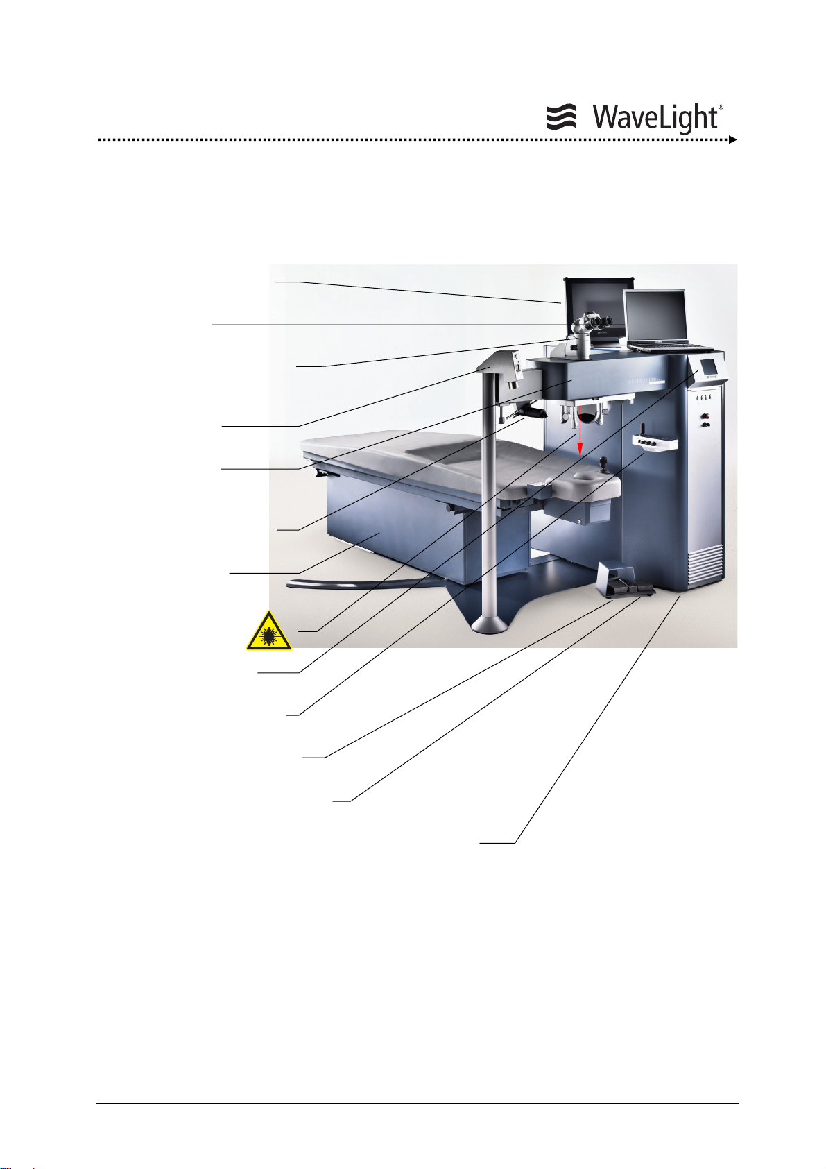
4.1. System Overview
Eyetracker Monitor
Notebook
Operation Microscope
Ablation Depth
Micrometer
Optics Arm
LED Slit Illumination
System
Patient Bed
(Pivoting optional)
Laser Aperture
LCD Screen
Figure 1: ALLEGRETTO WAVE EYE-Q Laser System (With Optional Accessories)
Control Panel
Laser Pedal
Center Pedal
ALLEGRETTO WAVE EYE-Q
Laser Console
ALLEGRETTO WAVE EYE-Q 1010 User Manual en / Rev.9 / 09-06-08 Item No.: 6638 2001 Page 23 of 232
Page 24
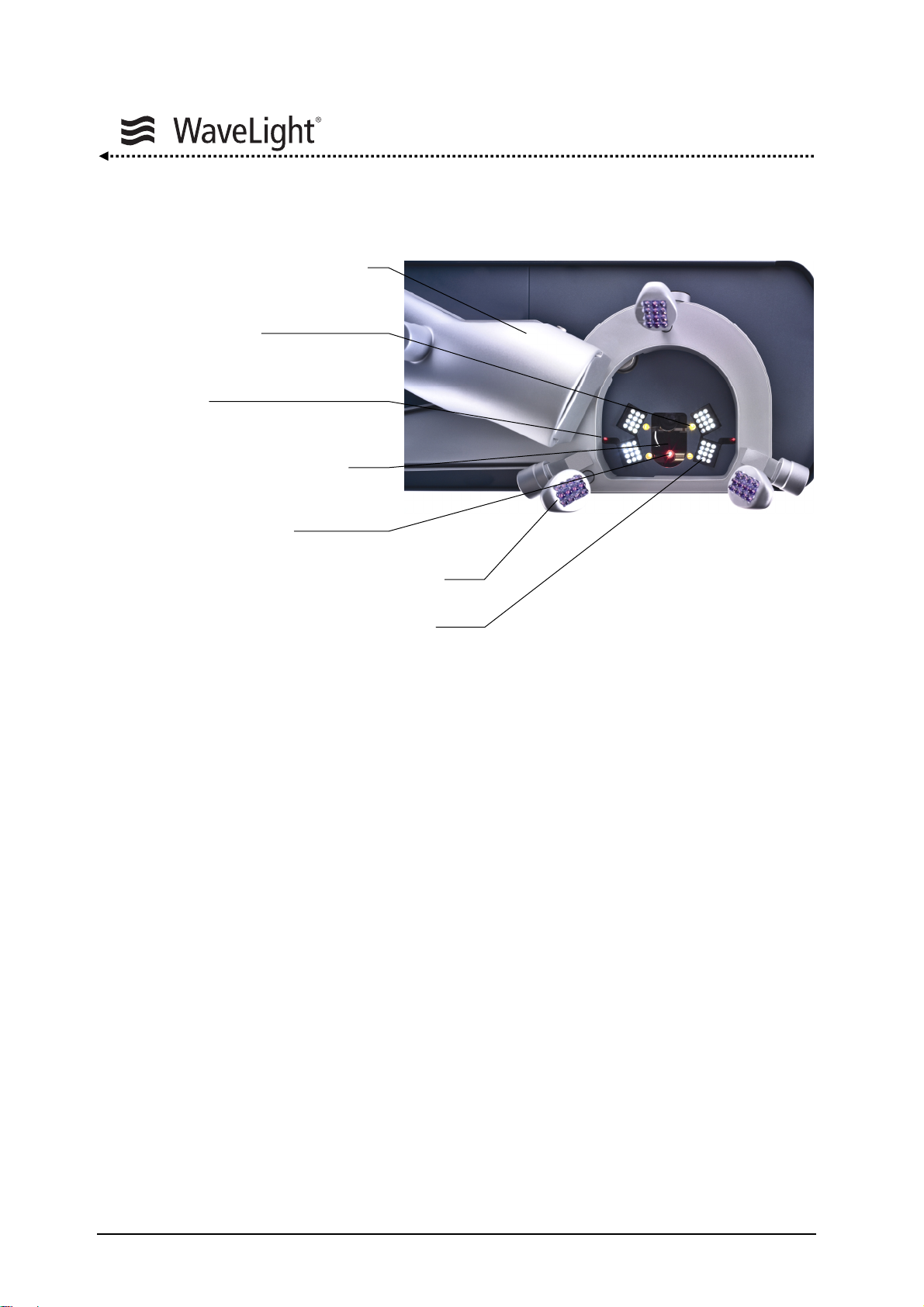
4.2. Lighting
Plume Evacuation Air Intake
Eyetracker LED's For
“Neuro Track”
Red Continuous Distance
Diodes
Green Flashing Fixation Light,
AND Cross Line Projector
(concealed)
Red Aiming Beam
Eyetracker Illumination (Infrared Light)
Microscope Illumination (White Light)
Figure 2: Integrated Radiation Sources
Figure
2 gives an overview of the integrated radiation sources.
System Description
Two superimposing red diode laser beams (distance diodes) define the treatment plane
at the intersection point of the two diodes.
In addition a green, flashing LED serves as a fixation target for the patient. It is coaxial to
the optical axis. The patients can see this target only in a small area based on the
viewing angle.
A cross line projector enables the alignment of the patient’s head.
The beam axis of the aiming beam laser diode is coaxial to the excimer beam axis and
used as the centering check.
The infrared lighting is necessary for the function of the eyetracker. The infrared lighting
arrays are mounted on a lever that can be turned for comfortable preparation of the eye.
Special white light emitting LED arrays are integrated for the illumination of the eye.
They are responsible for the bright, high contrast picture of the operation microscope.
A plume evacuator can be used to remove the ablation debris (option).
Page 24 of 232 ALLEGRETTO WAVE EYE-Q 1010 User Manual en / Rev.9 / 09-06-08 Item No.: 6638 2001
Page 25
System Description
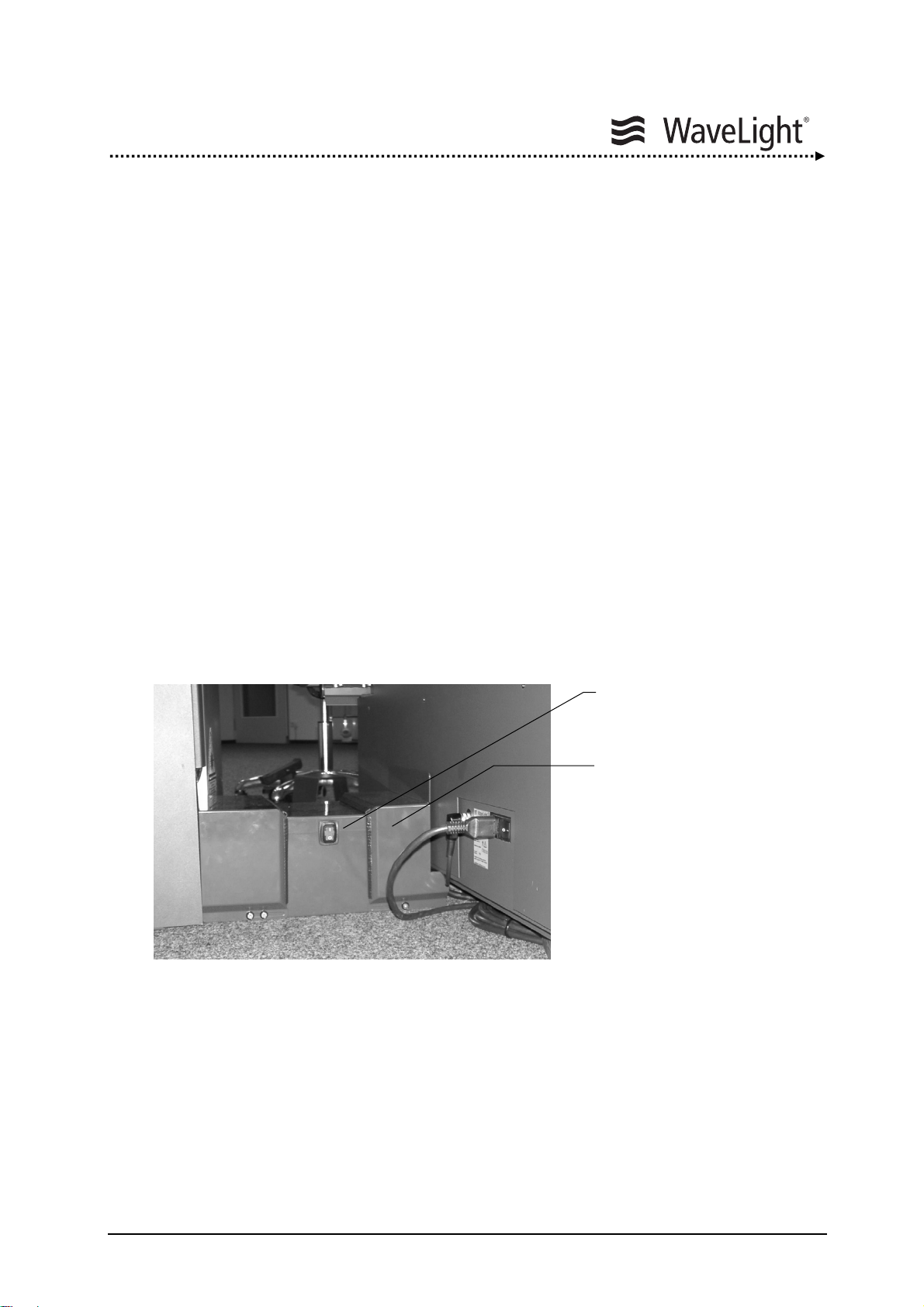
4.3. Switching Elements And Interfaces
System Main Switch:
All components of the ALLEGRETTO WAVE EYE-Q laser system that require mains
voltage are powered from the Mains Distribution Box.
The System Main Switch on the Mains Distribution Box controls all system power.
The switch is lit when it is switched on.
Components typically powered from the Mains Distribution Box:
• Laser Console
• Eyetracker Monitor
• Patient Bed
• LED Slit Illumination System
• Notebook Computer
The Mains Distribution Box is located between laser console and patient bed.
It must only be opened by authorized service personnel.
Figure 3: Mains Distribution Box With System Main Switch
System Main Switch
Mains Distribution Box
ALLEGRETTO WAVE EYE-Q 1010 User Manual en / Rev.9 / 09-06-08 Item No.: 6638 2001 Page 25 of 232
Page 26
System Description
1 2 3
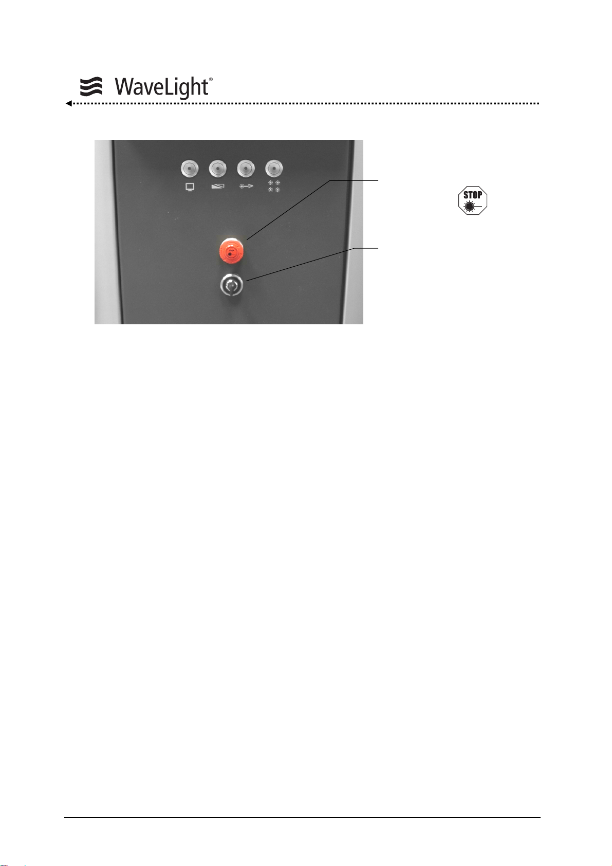
Figure 4: Key Switch And Emergency Laser Emission Stop Switch On The Front Of The Device
Key Switch:
The Key Switch is for turning the laser device on and off. The key can also be removed
to prevent unauthorized system use. It has three positions:
Emergency Laser Emission
Stop Switch
Key Switch
1 = OFF
2 = ON
3 = START
Emergency Laser Emission Stop Switch:
The Emergency Laser Emission Stop Switch allows the laser system to immediately shut
down the laser emission in case of an emergency so that any injuries to persons or
damages to the device can be avoided through reaction of the user. Pressing the
Emergency Laser Emission Stop Switch does not disconnect the device from the mains
supply. Pressing the red button activates the switch. The button must be released before
the laser can be turned on again by turning the red knob clockwise.
Page 26 of 232 ALLEGRETTO WAVE EYE-Q 1010 User Manual en / Rev.9 / 09-06-08 Item No.: 6638 2001
Page 27

System Description
I
O
ArF-Gas Valve
Handle
N2 -Gas Valve
Handle
Figure 5: Elements On The Rear Side Of The Device
Main Power Cable Outlet:
The power cord is firmly attached to the laser device and comes fitted with a plug.
Main Power Switch:
The Main Power Switch is used for turning on the laser device. After switching ON
(position I) the Main Power Switch the device is operational and can be activated via the
Key Switch.
Notebook Interface:
Via this standard interface and with the use of a special program provided by
WaveLight AG, the ALLEGRETTO WAVE EYE-Q can be operated via notebook.
Main Power Cable Outlet
Main Power Switch
Removable Cover To Gas
Cylinder Compartment
Interface Opt. Video System
Interface ET Monitor
Interface Notebook
Remote Interlock Connector
Foot Pedal Unit Outlet
Patient Bed Outlet
ALLEGRETTO WAVE EYE-Q 1010 User Manual en / Rev.9 / 09-06-08 Item No.: 6638 2001 Page 27 of 232
Page 28
System Description
Remote Interlock Connector:
An external contact can be plugged into the remote interlock connector to interrupt the
laser treatment if the laser room door is opened during treatment. If no external contact
is used, the remote interlock plug that is delivered with the laser device should be
plugged into the remote interlock connector outlet.
If neither an external contact nor a remote interlock plug is plugged in, the
laser device will not operate. The following message will appear on the
display: “Door Contact”.
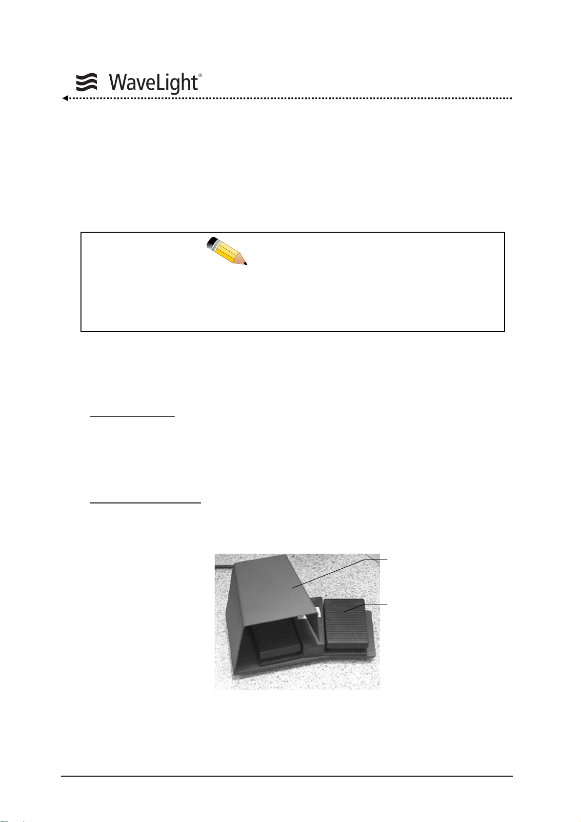
Foot Pedal Unit:
The foot pedal unit consists of two pedals:
Laser Foot Pedal:
The left pedal, the LASER foot pedal (LASER pedal), controls
the emission of the laser during treatment. It is fitted with a
bow guard to prevent activating the laser unintentionally.
Pressing this pedal starts the treatment. To interrupt the
treatment, lift your foot off the pedal. The treatment can be
continued by activating the LASER foot pedal again.
Center Test Foot Pedal
: The right pedal is the CENTER Test foot pedal (CENTER
pedal). This pedal serves to check the centering of the
ablation.
Figure 6: LASER Foot Pedal And CENTER Test Foot Pedal
NOTE
LASER Pedal
CENTER Pedal
Page 28 of 232 ALLEGRETTO WAVE EYE-Q 1010 User Manual en / Rev.9 / 09-06-08 Item No.: 6638 2001
Page 29
System Description
A
Patient Bed:
The patient is brought into proper position via the patient bed control unit. Precise
information on adjusting the bed can be found in the patient bed User Manual. Since the
ALLEGRETTO WAVE EYE-Q automatically switches off the power to the bed during
laser emission for safety reasons, the patient bed cannot be moved during treatment.
Because of this safety-switching feature, the patient bed can only be moved
when the ALLEGRETTO WAVE EYE-Q is turned on.
In case of collision hazard between eyetracker illumination and patient head,
the patient bed power is switched off automatically, if the patient’s head
touches the eyetracker illumination assembly.
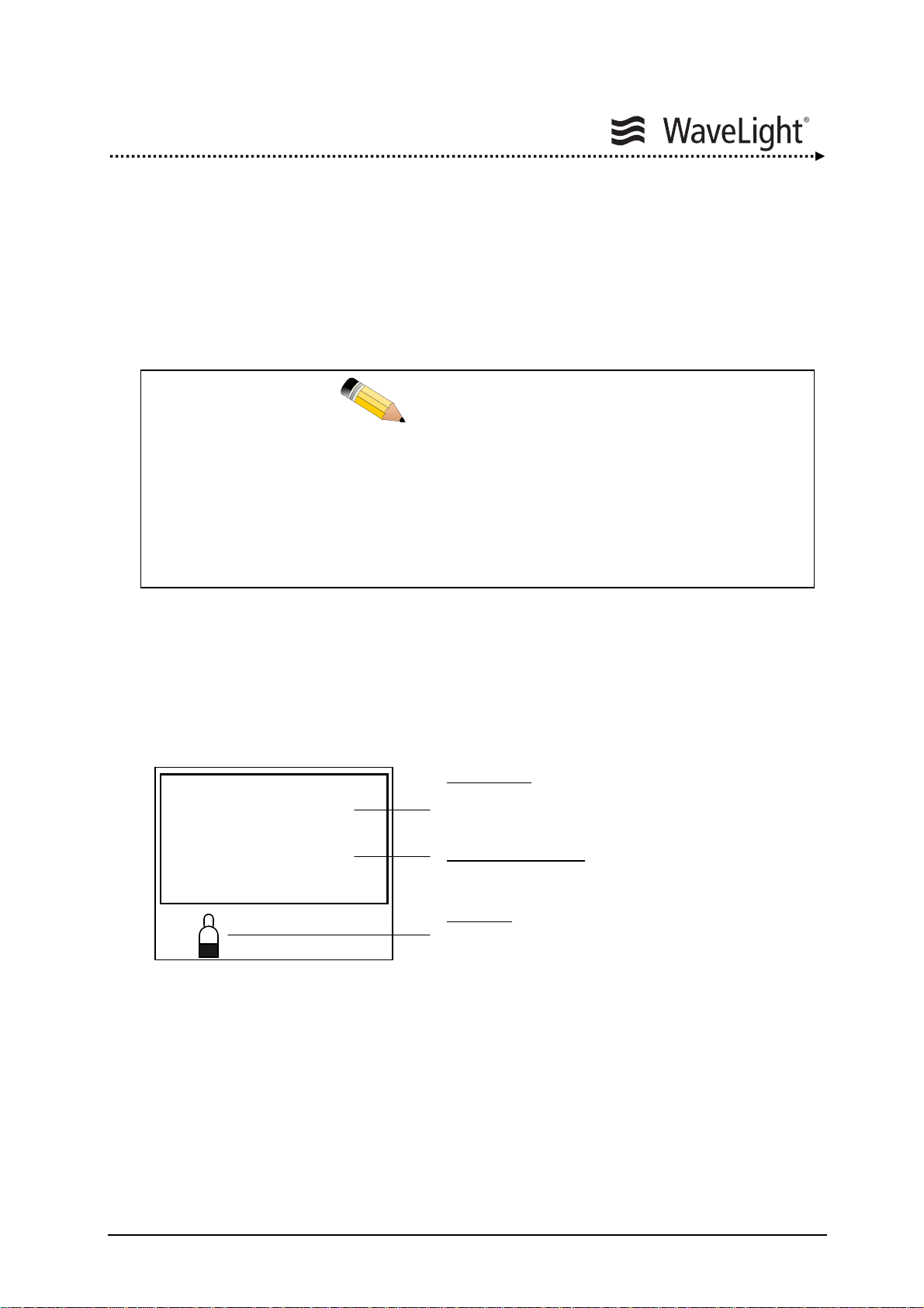
LCD Screen:
Instructions for the user as well as important laser and application parameters are
indicated on the LCD screen of the laser console.
SYSTEM CHECK
Instruction and
Information Lines
rF
Figure 7: Display Instructions
NOTE
Notification
For example the system
is in System Check.
General Indication
Status notifications
Symbols
For example a gas
cylinder symbol.
ALLEGRETTO WAVE EYE-Q 1010 User Manual en / Rev.9 / 09-06-08 Item No.: 6638 2001 Page 29 of 232
Page 30
System Description
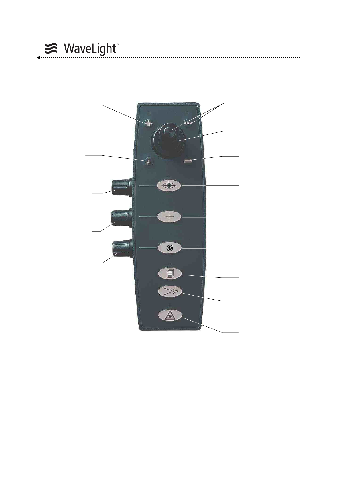
Control Panel With Joystick:
Gas Key
Not Used
Eyetracker
Adjustment
Cross Line
Brightness
Microscope
Illumination
Brightness
Figure 8: Control Panel With Joystick
The control panel consists of a foil keypad with integrated LED's, control knobs and a
joystick (positions: up / down, left / right)
The joystick serves the purpose of confirming routines as well as selecting parameters
during the “System Check”, “Setup Menu” and furthermore during “Treatment Mode”.
By pressing a foil key, general functions will be carried out or continued.
OK Key
Joystick
Not Used
Eyetracker Key
ON / OFF
Cross Line Key
ON / OFF
Aiming Beam Key
ON / OFF
Setup Key
Distance Diodes
ON / OFF
Ready Key
Page 30 of 232 ALLEGRETTO WAVE EYE-Q 1010 User Manual en / Rev.9 / 09-06-08 Item No.: 6638 2001
Page 31
System Description
Eyetracker Adjustment:
The operating principle of the eyetracker is that the patient’s pupil reflects the emitted
infrared light less strongly than the iris. The reflected infrared light is recorded by the
eyetracker camera and converted into a black and white image that is used for the rapid
image processing. The computational algorithm changes the grey scale value
(brightness) at which the transition between pupil and iris is optimal. The manual
adjustment is made by turning the knob on the control panel. The tracker pupil is marked
with a green cross and the border of the pupil with white dashes as soon as the pupil is
detected from the eyetracker.
Adjusting The Brightness Of The Microscope Illumination:
The brightness of the microscope illumination can be adjusted by turning the knob.
Gas Key:
This key is used as a confirmation key during all routines for which ArF-Premix-gas or
Nitrogen-gas is required.
OK Key:
The OK Key is the universal confirmation key. The key’s situation-dependent functions
are found in the corresponding texts appearing on the LCD screen.
Eyetracker Key:
The eyetracker is turned on and off via this key. In the “Treatment Window” the status is
indicated on the LCD screen of the laser console and the corresponding LED is switched
on at the control panel. To disable the eyetracker this key must be pressed for at least
2 seconds.
We strongly recommend to use the eyetracker during the treatment.
Cross Line Key:
This key is used to switch the cross line projector on and off. After turning ON, the cross
line projector always is set to the maximum brightness. The brightness of the cross line
projector can be adjusted by turning the corresponding knob.
NOTE
ALLEGRETTO WAVE EYE-Q 1010 User Manual en / Rev.9 / 09-06-08 Item No.: 6638 2001 Page 31 of 232
Page 32

System Description
Aiming Beam:
The aiming beam is turned on and off via this key when the system is in “Treatment
Mode”. The brightness of the aiming beam can be set in the “Setup Menu”. This setting
is then saved as the default value.
Distance Diodes:
The distance diodes (focus diodes) are turned on and off via this key when the system is
in “Treatment Mode”. The brightness of these diode lasers can be set in the “Setup
Menu”. This setting is then saved as default value.
Ready Key:
Pressing the Ready Key places the laser system in the “Ready / Operational Mode” after
which the treatment may begin. Status indicators are the LED above the key as well as
the Ready sign of the LCD screen. Repeated pressing the Ready Key switches the laser
system back into the “Standby Mode”.
Using the notebook program to activate the ALLEGRETTO WAVE EYE-Q's remote
control option the Ready Key of the notebook has to be pressed first.
After the “Ready Key” has been pressed, the laser energy is once again
checked internally, resulting in a delay between the moment the key is pressed
and the appearance of the READY symbol on the display. After several
minutes the system resets the READY state if the treatment has not been
started and switches into the “Standby Mode”.
By default, the eyetracker is active at this point. Thus, after switching the
system to READY and before starting with the treatment, the function of the
eyetracker must be checked by pressing the CENTER pedal (right pedal). This
will be prompted on the display.
The default settings for treatments are: Eyetracker ON
These settings have to be used during treatment.
NOTE
Distance Diodes ON
Aiming Beam OFF
Cross Line Projector final selected
setting
Page 32 of 232 ALLEGRETTO WAVE EYE-Q 1010 User Manual en / Rev.9 / 09-06-08 Item No.: 6638 2001
Page 33

System Description
Fixation Light Block Out Key:
The blinking green fixation light cannot be permanently switched off. However, in order
to check whether the patient is correctly fixating on the light, it can be switched off
temporarily via the corresponding switch located on the front cover (see figure
Eyetracker Dynamic Test Key:
For the purpose of determining whether the eyetracker can accurately track the pupil in
the entire permissible treatment field, four blinking yellow LED’s are mounted around the
beam emission aperture as alternative fixation targets. They can be activated by the
corresponding switch located on the front cover (see figure
White Balance Control Key:
The white balance of the video system is automatically set and fixed by detecting the
characteristic / color temperature of the light source through the lens and controlling the
amplification of red and blue signal. The white balance can be activated by pressing the
corresponding switch located on the front cover (see figure
Eyetracker Dynamic Test Key
Fixation Light Block Out Key
White Balance Control Key
Change Input TFT-Monitor
(currently not available)
Figure 9: Switches Located Below The LCD screen
9 below).
9 below).
9 below).
ALLEGRETTO WAVE EYE-Q 1010 User Manual en / Rev.9 / 09-06-08 Item No.: 6638 2001 Page 33 of 232
Page 34

System Description
Optional UPS Uninterruptible Power Supply:
If there is a grid failure it is not allowed to start a new treatment.
The ALLEGRETTO WAVE EYE-Q laser system is optionally powered through an
Uninterruptible Power Supply (UPS). This device shall safeguard the system against
sudden power loss that could cause abortion of a started treatment or test procedures.
The UPS provided by the manufacturer does also a power and a frequency conversion
to meet the power requirements of laser console and certain accessories. For details
please refer to the Site Preparation Instructions.
Make sure that the UPS is permanently connected to mains and the Main Switch on the
rear side of the UPS is always in RUN position. Otherwise the batteries inside the UPS
will not be charged. This may lead to failure of the UPS in case of a power loss.
WARNING
Please refer to the User Manual of the UPS.
Figure 10: Uninterruptible Power Supply
Page 34 of 232 ALLEGRETTO WAVE EYE-Q 1010 User Manual en / Rev.9 / 09-06-08 Item No.: 6638 2001
Page 35
Functional Description
5. FUNCTIONAL DESCRIPTION
Should signs of erroneous treatment data or system malfunctioning become
apparent, do not continue with the treatment to avoid irreversible injury to the
patient. For said reason, only qualified and experienced personnel may
operate the laser system. A WaveLight AG authorized service technician
performs the installation and functional check of the laser. An authorized
clinical trainer will instruct the surgeon and staff members in the use of the
ALLEGRETTO WAVE EYE-Q laser.
5.1. Important Steps Before Turning On The System
The user is responsible for determining that the laser system is functioning correctly and
that the system is in good working condition before using it.
To accomplish this, the following points must be considered:
WARNING
• The laser device, accessories and connecting cables are to be inspected for visible
damage.
• The gas supply must not show any leaks.
• The Emergency Laser Emission Stop Switch is to be released, if it has been
activated (see figure
The Front Of The Device” on page 26).
• Local regulations must be taken into consideration.
Things to do before initial use:
• Please pay attention to the appropriate User Manuals.
• Plug the power cable into a separate grounded outlet. Multiple-purpose and non-
fixed outlets may not be used (see chapter
• Attach the foot pedal unit to the rear side of the device.
• Attach the remote interlock connector plug.
• Connect the patient bed and the laser with the electrical cable.
4 “Key Switch And Emergency Laser Emission Stop Switch On
12 “Technical Data” from page 222).
ALLEGRETTO WAVE EYE-Q 1010 User Manual en / Rev.9 / 09-06-08 Item No.: 6638 2001 Page 35 of 232
Page 36

Functional Description
5.2. Structure Of The ALLEGRETTO WAVE EYE-Q Firmware
Self Test of the Controller
Internal Test
Manual Input of
Treatment Data
Figure 11: Firmware Structure
The system has to be turned on via the System Main Switch, the Main Power Switch and
the Key Switch (see chapter
5.3 “Turning On The System” on page 37). The
ALLEGRETTO WAVE EYE-Q will automatically conduct a Self Test of the control
module. The System Check follows once the Self Test has been completed. The user
has to actively participate during the procedure of the System Check. The system
proceeds to the “Standby Mode” after completing the System Check. The “Standby
Mode” is exited by pressing the OK Key or by starting the remote notebook software. In
the first case data is entered directly via the control panel. Data is entered into the
notebook in the case that the remote notebook software is being used. This gives the
user the possibility to enter data prior the treatment. After completing the treatment the
ALLEGRETTO WAVE EYE-Q conducts an internal check and returns to the “Standby
Mode”. The “Setup Menu” can be activated in the “Standby Mode” as well as in the
“Treatment Mode”. This enables the user to enter parameters and conduct system
related procedures. The ALLEGRETTO WAVE EYE-Q can be turned off via the Key
Switch.
Turn the
Key Switch
System Check
Standby
Input of Treatment
Data via Notebook
Treatment Setup Menu
Setup Menu
Page 36 of 232 ALLEGRETTO WAVE EYE-Q 1010 User Manual en / Rev.9 / 09-06-08 Item No.: 6638 2001
Page 37

Functional Description
5.3. Turning On The System
Switch on the system at the System Main Switch located between laser console and
patient bed (see chapter
Distribution Box With System Main Switch” on page 25).
Then switch on the unit at the Main Power Switch located at the rear side of the laser
console (see figure 5 “Elements On The Rear Side Of The Device” on page 27).
Power up the system components. Functioning of notebook computer, eyetracker
monitor, patient bed and plume evacuator are mandatory for tests and treatments.
4.3 “Switching Elements And Interfaces”, figure 3 “Mains
Turn the Key Switch in a clockwise direction (see figure
4 “Key Switch And Emergency
Laser Emission Stop Switch On The Front Of The Device” on page 26) after the portal
software has prompted on the notebook. Hold the key in this position (3) until the
following appears on the LCD screen of the laser console:
PR XXXXXX
Firmware Version
Figure 12: LCD Screen - Start Window
When the laser is turned on, it will conduct a Self Test and a System Check.
The Self Test will run automatically after the laser has been turned on, however, the user
must actively participate in the System Check.
If the laser device does not turn on, check to see if the System Main Switch
and/or the Emergency Laser Emission Stop Switch has been released. The
Emergency Laser Emission Stop Switch is released by turning the red knob
clockwise.
The firmware version will also appear on the display below the “WaveLight”
logo.
NOTE
ALLEGRETTO WAVE EYE-Q 1010 User Manual en / Rev.9 / 09-06-08 Item No.: 6638 2001 Page 37 of 232
Page 38
Functional Description
5.3.1. Logfile Option
The System Check involves checking the state of the ALLEGRETTO WAVE EYE-Q and
recording the relevant data.
The operational parameters of the ALLEGRETTO WAVE EYE-Q are permanently traced
and stored in the internal logfile.
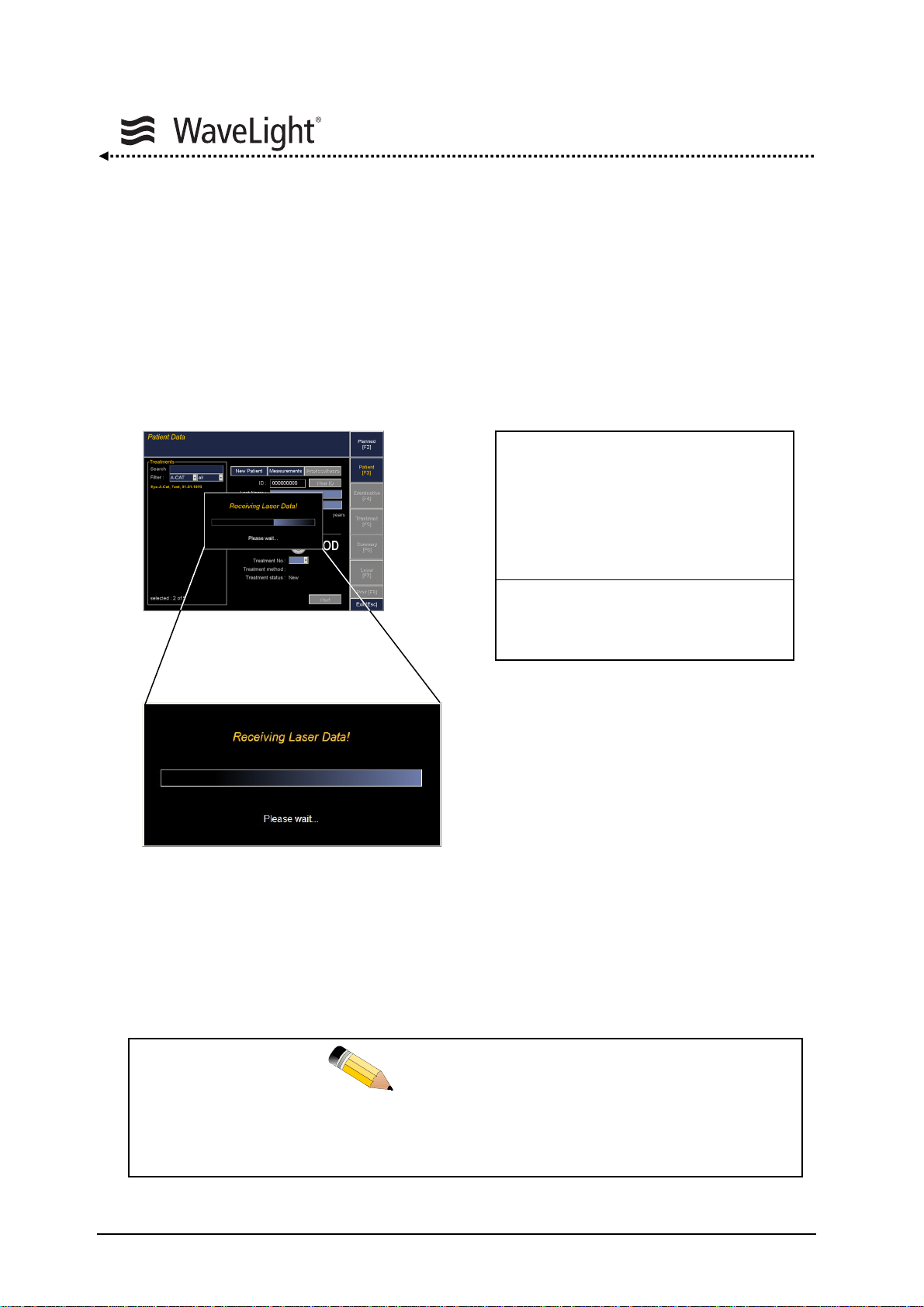
After the start of the ALLEGRETTO WAVE EYE-Q laser using the notebook, data are
automatically sent to the notebook.
Data transfer is running
Figure 13: Display Notebook - Logfile Operation Figure 14: LCD Screen - Logfile Operation
With no notebook being connected, the system waits 5 min. This waiting time may be
interrupted by pressing the OK Key. See figure
15 “LCD Screen At The Laser Unit” on
page 39.
This data transfer should be performed for each working day.
NOTE
Page 38 of 232 ALLEGRETTO WAVE EYE-Q 1010 User Manual en / Rev.9 / 09-06-08 Item No.: 6638 2001
Page 39

Functional Description
Saving Laser Data With The “Save Logfiles” Function:
With this function you can store laser data on a USB-stick and send them to your
ALLEGRETTO WAVE EYE-Q service representative. This function allows a distant
diagnostic of the system to prevent problems or to remedy them.
In the logfile the following data are transferred from the ALLEGRETTO WAVE EYE-Q to
the notebook:
• Current configuration of the laser device
• List of system parameters and settings during the last treatments
• List of warnings and errors which have occurred during the last treatments
First switch on the notebook connected to the ALLEGRETTO WAVE EYE-Q and wait
until the notebook has successfully completed the boot process. Subsequently, turn on
the ALLEGRETTO WAVE EYE-Q laser system. System data are transferred
automatically (see figure
successful completion of data transfer, the laser system ALLEGRETTO WAVE EYE-Q
automatically goes on with the System Check.
In case the notebook has not booted, the following user prompt is displayed for 5 min.:
“Remaining time 300 sec”
Start notebook program
to complete system diagnostic
or continue with OK KEY
Figure 15: LCD Screen At The Laser Unit
If the system detects a notebook within the 5 min waiting time, the transfer starts.
If you do not want to transfer data or wish to work without notebook, then press the OK
Key on the control panel. The system will then proceed with the System Check without
transferring the logfile.
13 “Display Notebook - Logfile Operation” on page 38). Upon
ALLEGRETTO WAVE EYE-Q 1010 User Manual en / Rev.9 / 09-06-08 Item No.: 6638 2001 Page 39 of 232
Page 40

Functional Description
Save Data:
To save the data to a USB-stick, open the “Setup Window” on your notebook. Insert a
virus-free USB-stick into the USB-port and press the “Save Data” button to confirm. In
case the transfer process has been successfully completed, a message window appears
on the notebook screen. To confirm the message, press OK. For further information,
please also refer to chapter
With the “Save Logfiles” function two files are stored:
File name Contents
File 1: lasercfg.log Configuration of the laser console
File 2: laseropm.log Treatment data and list of messages occurred
as well as status software version
5.6.10 “Setting Menu” from page 118.
Page 40 of 232 ALLEGRETTO WAVE EYE-Q 1010 User Manual en / Rev.9 / 09-06-08 Item No.: 6638 2001
Page 41

Functional Description
5.3.2. Self Test
The Self Test is an internal procedure that does not require user participation.
The following items are inspected during the Self Test:
• the central processor
• the memory in regard to the procedure program
• the memory in regard to the treatment lists
• the communication with the excimer laser head
After successfully completing the Self Test, the system continues with the System
Check.
ALLEGRETTO WAVE EYE-Q 1010 User Manual en / Rev.9 / 09-06-08 Item No.: 6638 2001 Page 41 of 232
Page 42

Functional Description
5.4. System Check
The System Check tests function elements of the ALLEGRETTO WAVE EYE-Q that are
important for its proper operation. There are tests that require feedback from the user as
well as tests that are performed automatically.
The laser unit carries out the following tests during the System Check:
• Nitrogen-gas pressure for flushing of the optical path
• ArF-Premix-gas pressure
• Laser head pressure
• Internal laser energy
• Pulse energy at beam aperture
• Eyetracker function
The System Checks are described in the following sections of this User Manual.
5.4.1. General Information About The System Check
Completing the System Check can take up to 12 minutes, if a gas change is carried out.
The control panel is partially inoperative during the System Check, so that you cannot
use the “Setup Menu”.
A manual gas change does not need to be carried out, if you are sure that the laser
energy is still sufficient, but it is strongly recommended to perform a gas change at the
beginning of each treatment day.
After a successful System Check the laser system shifts automatically into
“Standby Mode”.
When using the laser panel, the “Treatment Selection Menu” can be started at
this point by pressing the OK Key. Alternatively, the notebook program can be
used to activate the ALLEGRETTO WAVE EYE-Q's remote control option.
NOTE
Page 42 of 232 ALLEGRETTO WAVE EYE-Q 1010 User Manual en / Rev.9 / 09-06-08 Item No.: 6638 2001
Page 43
Functional Description
5.4.2. Check Of Nitrogen-Gas Pressure And Beam Path Flushing
Purpose:
User Assistance:
Feedback:
Follow the system instructions, i.e. open the Nitrogen-gas cylinder and confirm by
pressing the Gas Key.
Figure 16: LCD Screen - Open Gas Cylinder (N2)
Inspection of the quantity and pressure in the Nitrogen-gas cylinder.
Opening of the Nitrogen-gas cylinder (N2).
Request for opening of the cylinder by the user, warning in case of
low Nitrogen-gas pressure, error message in case of defect.
SYSTEM CHECK
Open Gas Cylinder
and confirm with GAS KEY
N2
ALLEGRETTO WAVE EYE-Q 1010 User Manual en / Rev.9 / 09-06-08 Item No.: 6638 2001 Page 43 of 232
Page 44
Functional Description
The system will then start flushing the optical pathway with Nitrogen-gas. This is
necessary to ensure that the pulse energy remains constant throughout the operation.
SYSTEM CHECK
Purging beam path
N2
Figure 17: LCD Screen - Status Of Beam Path Flushing (N2)
• Below a certain pressure, the system displays the pressure to remind the
user to order a new Nitrogen-gas cylinder (N2).
• If the pressure descends below a certain level, no further treatments will be
allowed.
• The Nitrogen-gas cylinder must not be closed before all treatments have
been done.
Please wait
300 sec
NOTE
Page 44 of 232 ALLEGRETTO WAVE EYE-Q 1010 User Manual en / Rev.9 / 09-06-08 Item No.: 6638 2001
Page 45

Functional Description
A
5.4.3. ArF-Premix-Gas Pressure
Purpose
User Assistance
Feedback:
The ArF-Premix-gas cylinder must first be opened. To do so, turn the upper valve on the
rear side of the cylinder counter-clockwise at least one full turn.
See figure
Figure 18: LCD Screen - Open Gas Cylinder (ArF)
If the ArF-Premix-gas cylinder contains only enough gas for a few fills, a
message will appear on the display bringing this to the user’s attention. The
user must confirm this message. As a reminder, the gas cylinder symbol then
appears on the display during treatment.
As soon as the content of the ArF-Premix-gas cylinder descends below a
certain minimum level, a service message appears on the display. In such
case, beginning another treatment will no longer be possible.
: Inspection of the pressure in the ArF-Premix-gas cylinder.
: Opening and closing the ArF-Premix-gas cylinder valve.
Request for the user to open and close the ArF-Premix-gas cylinder,
pressure values in the laser head, warning in case of premix low
pressure, error messages in case of defects.
5 “Elements On The Rear Side Of The Device” on page 27.
SYSTEM CHECK
Open Gas Cylinder
and confirm with GAS KEY
rF
NOTE
ALLEGRETTO WAVE EYE-Q 1010 User Manual en / Rev.9 / 09-06-08 Item No.: 6638 2001 Page 45 of 232
Page 46

A
A
A
The following sequence appears on the LCD screen of the laser console:
SYSTEM CHECK
Pressure Check
Please wait
rF
Figure 19: LCD Screen - ArF-Premix-Gas Pressure And Leakage Test
SYSTEM CHECK
Check premix pressure
Laser Head
rF
Figure 20: LCD Screen - Pressure Check Laser Head
SYSTEM CHECK
Pressure Test
Laser Head
rF
Figure 21: LCD Screen - Leakage Test Laser Head
Functional Description
Page 46 of 232 ALLEGRETTO WAVE EYE-Q 1010 User Manual en / Rev.9 / 09-06-08 Item No.: 6638 2001
Page 47

Functional Description
A
Follow the instructions on the LCD screen and press the Gas Key at the
control panel. If the Gas Key has not been pressed within 10 min. the system
will turn itself off.
The system checks to see whether the ArF-Premix-gas cylinder has been
opened. If the cylinder has not been opened, the system, after running the
corresponding inspection, will again request that the ArF-Premix-gas cylinder
must be opened.
A gas change of the ArF-Premix-gas in the laser head should be carried out at
least once a day when turning on the system for the first time.
The system will generally ask if a gas change should take place. This
procedure is skipped when any other button on the control panel is pressed
except the Gas Key.
SYSTEM CHECK
Perform manually activated
GAS CHANGE?
Yes = GAS KEY; Skip = OTHER KEY
rF
Figure 22: LCD Screen - Gas Change
NOTE
5.4.4. Laser Head Pressure
Purpose:
User Assistance:
Feedback:
ALLEGRETTO WAVE EYE-Q 1010 User Manual en / Rev.9 / 09-06-08 Item No.: 6638 2001 Page 47 of 232
Pressure inspection of the laser head, valve-block air-tightness
inspection.
None
Pressure values, error messages in case of defects.
Page 48
The following sequence appears on the LCD screen of the laser console:
SYSTEM CHECK
Pressure Check
Please wait
Figure 23: LCD Screen - Pressure Check Laser Head
SYSTEM CHECK
Evacuation ArF Premix line
4560 mbar
Figure 24: LCD Screen - Evacuation Of The ArF Premix Line
SYSTEM CHECK
Check of pressure ArF Cylinder
Figure 25: LCD Screen - Pressure Check ArF Cylinder
Functional Description
Page 48 of 232 ALLEGRETTO WAVE EYE-Q 1010 User Manual en / Rev.9 / 09-06-08 Item No.: 6638 2001
Page 49

Functional Description
A
SYSTEM CHECK
GAS CHANGE ArF
Figure 26: LCD Screen - Running Gas Change
SYSTEM CHECK
GAS CHANGE ArF
Figure 27: LCD Screen - Status Gas Change
SYSTEM CHECK
Close ArF Gas Cylinder
and confirm with GAS KEY
rF
Figure 28: LCD Screen - Close ArF Cylinder - The Gas Change Has Been Finished
10
80 mbar
5940 mbar
5945 mbar
ALLEGRETTO WAVE EYE-Q 1010 User Manual en / Rev.9 / 09-06-08 Item No.: 6638 2001 Page 49 of 232
Page 50

Functional Description
5.4.5. Check And Calibration Of The Internal Laser Energy
A routine is integrated that checks intensively the relation between the internal energy
sensors. After each “GAS CHANGE ArF” this procedure starts automatically. If the
calibration of the sensors is ok, no user interaction is necessary, but it is important not to
switch off the system during the calibration procedure. If the calibration is not ok, please
follow the instructions displayed on the LCD screen of the laser console.
Purpose:
User Assistance:
Feedback:
Figure 29: LCD Screen - Warming Up Laser Head
This routine will check the internal energy after gas change and does not
always occur.
The system reports “Warming Up Laser Head”. This phase lasts 10 seconds.
Warming up of the laser head, setting of the recommended energy.
If the laser energy is too low, the system automatically conducts a
gas change, and requires the user to open and close the valve of
the ArF-Premix-gas cylinder.
Status reports, possible request for the opening and closing the ArF-
Premix-gas cylinder, error message should the laser energy be too
low or too high.
SYSTEM CHECK
Warming Up Laser Head
NOTE
Page 50 of 232 ALLEGRETTO WAVE EYE-Q 1010 User Manual en / Rev.9 / 09-06-08 Item No.: 6638 2001
Page 51

Functional Description
The system then reports “Setting Laser Energy”. This involves the re-setting of
the internal energy value used during the previous treatment.
SYSTEM CHECK
SETTING LASER ENERGY
Preparing laser
Please wait
Figure 30: LCD Screen - Setting Laser Energy
The user will hear the pulsating noise of the excimer laser, however, since the
shutter is closed, the beam cannot exit the aperture.
If the recommended energy level cannot be internally achieved, the
ALLEGRETTO WAVE EYE-Q automatically performs a gas change. The user
will be prompted to open the ArF-Premix-gas cylinder and confirm by pressing
the Gas Key.
If the recommended energy level still cannot be internally achieved after this
second gas change, the system will issue an error message. Treatment will
not be possible. Contact your WaveLight AG authorized service
representatives.
NOTE
NOTE
ALLEGRETTO WAVE EYE-Q 1010 User Manual en / Rev.9 / 09-06-08 Item No.: 6638 2001 Page 51 of 232
Page 52

Functional Description
Calibration Of The Laser Energy At The Beam Aperture:
This request pops up after the gas change has been performed. The external Energy
Calibration is used to verify the internal energy setting after certain periods of time.
Purpose:
User Assistance:
Feedback:
Figure 31: LCD Screen - External Energy Measurement
Measurement of the pulse energy at the laser beam aperture with
the use of the integrated measuring head.
Swing the eyetracker illumination assembly in place, shift the
external energy sensor below the beam aperture, confirm with the
OK Key, press the LASER pedal for at least 15 seconds and
compare the measured energy with the recommended energy.
Status reports, possible request for pressing the LASER pedal, error
message, should the laser energy be too low or too high.
SYSTEM CHECK
EXTERNAL ENERGY CHECK
1. Mount ext Energy Sensor
2. Continue with OK KEY
Page 52 of 232 ALLEGRETTO WAVE EYE-Q 1010 User Manual en / Rev.9 / 09-06-08 Item No.: 6638 2001
Page 53

Functional Description
Make sure that the measurement head holder is completely slipped to the stop
before pressing the LASER pedal.
Figure 32: Calibrate Energy, Mount Sensor & OK Keys
• Shift the eyetracker illumination in. Be sure that it is pushed completely in.
• Shift the holder of the sensor head beyond the laser aperture completely to the stop.
CAUTION
ALLEGRETTO WAVE EYE-Q 1010 User Manual en / Rev.9 / 09-06-08 Item No.: 6638 2001 Page 53 of 232
Page 54

Functional Description
Figure 33: Press LASER Pedal
• Press the LASER pedal. Laser pulses are emitted onto the sensor head. The
measured energy is displayed. The so-called E/V value pair (E = relative laser head
energy value, V = relative laser head high voltage value) is updated every
1.200 pulses and appears on the lower right of the LCD screen of the laser console.
• After at least 15 seconds lift the foot off the LASER pedal and check whether the
measured value is within the tolerance of the target value that is shown on the LCD
screen.
Always press the LASER pedal for as long as it takes to get an updated
E/V value pair. This procedure can be repeated.
Shift the sensor head back to the stop after use.
The External Energy Check measures laser energy as it exits the laser aperture. The
external energy value is compared to a preset internal energy value.
The procedure is self-adjusting. No adjustments or interventions can be made by the
user.
LASER Pedal
NOTE
Page 54 of 232 ALLEGRETTO WAVE EYE-Q 1010 User Manual en / Rev.9 / 09-06-08 Item No.: 6638 2001
Page 55

Functional Description
At every Energy Check the following values are checked or taken into consideration:
• relative desired energy for the laser head (without dimension)
• absolute pulse energy at laser aperture [in mJ]
A relative desired energy for the laser head is always set. It is then checked whether the
correct pulse energy is available at the aperture.
The laser energy is one of the most important parameters for a successful
treatment. For this reason this calibration procedure is conducted during the
System Check. This procedure must also be repeated before every treatment
or if the last calibration occurred more than 30 minutes ago by selecting the
corresponding function in the “Setup Menu”. A sensor head is used that is
integrated in the eyetracker illumination lever.
Press the LASER pedal to emit laser pulses. After every 1.200 pulses the E/V value pair
(E = relative laser head energy value, V = relative laser head high voltage value) is
updated and appears on the right side of the LCD screen. It shows up the first time after
approx. 15 seconds. The relative laser head energy value has to be adjusted in relation
to the depth of the Fluence Test Disk (see chapter
The Control Systems” from page 152). To set a new energy value via the joystick, the
LASER pedal has to be released. After entering a new energy value the external energy
measurement has to be performed again. For saving the energy value, the OK Key has
to be pressed.
Always press the LASER pedal for at least 15 seconds. Press the OK Key
after comparing the measured and the recommended target energy.
NOTE
5.17 “Routine Test Procedures With
NOTE
ALLEGRETTO WAVE EYE-Q 1010 User Manual en / Rev.9 / 09-06-08 Item No.: 6638 2001 Page 55 of 232
Page 56

Functional Description
Problem: The required target energy cannot be achieved (i.e. the measured
value is out of tolerance), or can only be achieved with V value of more
than 98%.
Solution: A gas change is necessary. This is initiated by entering the “Setup
Menu” with the Setup Key and activating “New Fill ArF”. After the gas
change the external calibration must be performed again.
Problem: The required target energy cannot be achieved (i.e. the measured
value is higher), or can only be achieved with V value of less than 52%.
Solution: No further treatments can be performed.
Call your ALLEGRETTO WAVE EYE-Q service representative.
Do not attempt to change the Target Energy with the cursor during or after
External Energy Check unless the later Fluence Test (energy density
measurement) findings require this.
• Make sure that the measurement head is properly snapped into position.
• Only experienced pers onnel that have been trained in the use of the
system may calibrate the system.
• Slip the measurement head back into position after finishing the procedure.
WARNING
CAUTION
Page 56 of 232 ALLEGRETTO WAVE EYE-Q 1010 User Manual en / Rev.9 / 09-06-08 Item No.: 6638 2001
Page 57

Functional Description
Example:
SYSTEM CHECK
EXTERNAL ENERGY CHECK
Test 15 s With LASER PEDAL
1.87 +/-0.02 mJ = Target Energy
Factory setting 1.89 mJ
Figure 34: LCD Screen - Target Energy Check
In this example, the target energy range for the External Energy Check is
1.87 mJ ± 0.02 mJ (1.85 mJ - 1.89 mJ).
Depending on when the laser was last operated, the laser beam path may have to be
purged with nitrogen-gas prior to firing. This process is initiated when the LASER pedal
is depressed and will take about one minute to complete prior to the laser firing. The
countdown is displayed in the Energy Check screen as a decreasing number. It is not
possible to continue the energy check until the countdown has completed and
disappeared.
Purging beam path
1.87 +/-0.02 mJ = Target Energy
Factory setting 1.89 mJ
Figure 35: LCD Screen - Purging Beam Path
Please wait
42
ALLEGRETTO WAVE EYE-Q 1010 User Manual en / Rev.9 / 09-06-08 Item No.: 6638 2001 Page 57 of 232
Page 58

Functional Description
Start the External Energy Check by pressing and holding down the LASER pedal at least
till LCD screen shows “External Energy Check finished, release LASER pedal”. This will
take about 15 seconds.
SYSTEM CHECK
Repeat measurement = LASER PEDAL
1.89 mJ = measured energy
1.87 +/-0.02 mJ = Target Energy
Factory setting 1.89 mJ
Figure 36: LCD Screen - Energy Check Running
ENERGY CHECK: finished
leave LASER PEDAL
Repeat measurement = LASER PEDAL
1.89 mJ = measured energy
1.87 +/-0.02 mJ = Target Energy
Factory setting 1.89 mJ
Figure 37: LCD Screen - Energy Check Finished
E 63
V 70
Page 58 of 232 ALLEGRETTO WAVE EYE-Q 1010 User Manual en / Rev.9 / 09-06-08 Item No.: 6638 2001
Page 59
Functional Description
Save = OK KEY, Test = LASER PEDAL
Change Target Energy = ARROW KEYS
1.89 mJ = measured energy
1.87 +/-0.02 mJ = Target Energy
Factory setting 1.89 mJ
Figure 38: LCD Screen - Save Target Energy
Note that the External Energy 1.89 mJ in the pictured example is well within the
± 0.02 mJ tolerance of the Target Energy (1.87 mJ - 1.89 mJ).
After every 1.200 laser pulses the measured energy is displayed along with the
E (relative laser head energy) and V (relative laser head high voltage) values.
The V value should not exceed “98”. If so the system requires another gas change.
Finish the Energy Check and perform another gas change.
The Energy Calibration Check can be repeated by pressing and holding the LASER
pedal at least until the LCD screen prompts you to leave the LASER pedal.
If all values are within tolerances, press the “OK Key” to confirm the energy value.
Do not attempt to change the Target Energy with the joystick during or after
External Energy Check unless the later Fluence Test findings require this.
E 63
V 70
CAUTION
ALLEGRETTO WAVE EYE-Q 1010 User Manual en / Rev.9 / 09-06-08 Item No.: 6638 2001 Page 59 of 232
Page 60

Functional Description
If the LASER pedal is released before the LCD screen prompts you to do so and the OK
Key is pressed, the system will show “Measurement < 15 sec”. In this case, the message
has to be confirmed and the whole External Energy Check procedure has to be
repeated.
Measuring Time < 15 s
Continue With OK KEY
Figure 39: LCD Screen - Measurement Time Too Short
The laser system will perform a final Internal Nitrogen Pressure Check. Once the final
Pressure Check has been completed, the laser is ready to start a treatment and will ask
for treatment data.
Page 60 of 232 ALLEGRETTO WAVE EYE-Q 1010 User Manual en / Rev.9 / 09-06-08 Item No.: 6638 2001
Page 61

Functional Description
5.4.6. Eyetracker Test
Before the Eyetracker Test is being performed, the energy check has to be
successfully completed.
See chapter 5.4.5 “Check And Calibration Of The Internal Laser Energy” on
page 50.
The Eyetracker Test (ET-Test) verifies alignment of the eyetracker with the laser. The
test is performed on a daily basis (before surgery) and involves ablation of an Eyetracker
Test Target. Alignment of the eyetracker can be adjusted in the ET-Test sub-menu
“Calibration Eyetracker”. This sub-routine can be opened in the “ET-Test Menu” after the
ET-Test has been performed.
To carry out the Eyetracker Test, please refer to chapter
With The Control Systems” on page 152.
All parameters adjusted in this menu by the user will be saved after leaving the
“ET-Test Menu”.
NOTE
5.17 “Routine Test Procedures
NOTE
ALLEGRETTO WAVE EYE-Q 1010 User Manual en / Rev.9 / 09-06-08 Item No.: 6638 2001 Page 61 of 232
Page 62

Functional Description
5.4.7. Fluence Test
Before the Fluence Test is being performed, the energy check and the ET-Test
have to be successfully completed.
See chapter 5.4.5 “Check And Calibration Of The Internal Laser Energy” on
page 50 and chapter 5.4.6 “Eyetracker Test” on page 61.
The Fluence Test allows determination of the energy density of the laser at the treatment
plane. The test is performed on a daily basis (before surgery) and involves an ablation of
the Fluence Test Disk and allows measurement of the central ablation depth.
The Target Energy of the laser is set with the Fluence Test. Once the Target Energy has
been set, it must not be changed until another Fluence Test is performed.
To carry out the Fluence Test, please refer to chapter
With The Control Systems” on page 152.
After the System Check the ALLEGRETTO WAVE EYE-Q laser system will perform a
final Internal Nitrogen Pressure Check. Once the final Pressure Check has been
completed, the laser switches into “Standby Mode / Window” (see figure
- Standby” on page 65).
All parameters adjusted in this menu by the user will be saved after leaving the
Fluence Test Menu.
NOTE
5.17 “Routine Test Procedures
42 “LCD Screen
NOTE
Page 62 of 232 ALLEGRETTO WAVE EYE-Q 1010 User Manual en / Rev.9 / 09-06-08 Item No.: 6638 2001
Page 63
Functional Description
5.5. Treatment Direct Entry Without Notebook
Treatments may be carried out with or without the notebook. In either case, the system
behavior and the types of treatment remain identical.
It is recommended to use the Portal Software to enter the treatment data.
Please see chapter 5.6 “Navigation And Data Entry With The Notebook Portal
Software” on page 69.
The notebook computer serves as a tool for pre-programming and storing treatment
data. It serves also as a kind of remote control. It is, however, not necessary to use the
notebook. Data can be entered directly into the ALLEGRETTO WAVE EYE-Q.
The possibility to document the treatment is not given.
NOTE
ALLEGRETTO WAVE EYE-Q 1010 User Manual en / Rev.9 / 09-06-08 Item No.: 6638 2001 Page 63 of 232
Page 64
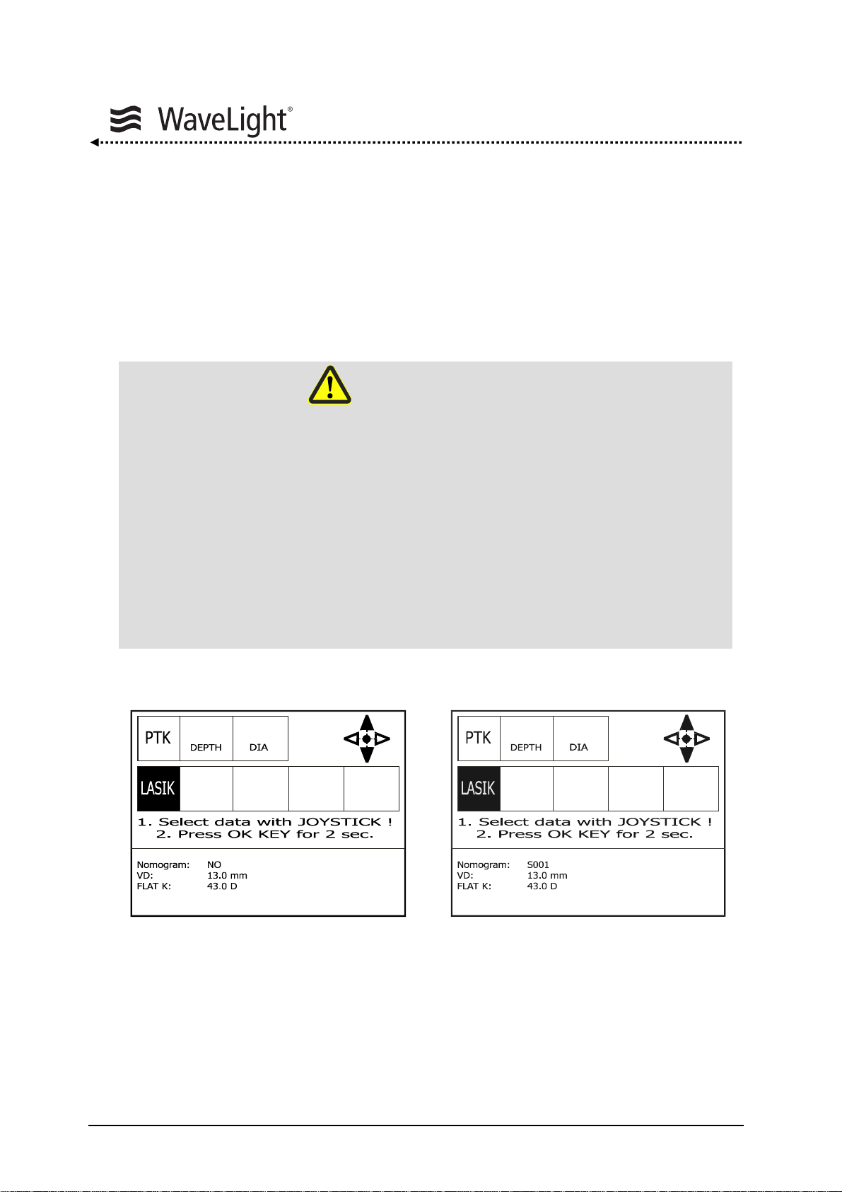
Functional Description
5.5.1. Nomogram
A nomogram is integrated in the laser console which is based on long-term results of
clinical studies. If you want to enable or disable the nomogram or if you have special
questions, please contact your ALLEGRETTO WAVE EYE-Q service representative.
The nomogram version is displayed on the LCD screen of the laser console during the
selection of treatment lists and must be absolutely considered.
Wavefront Optimized Nomogram “Nomogram: S001”
Personal Nomogram “Nomogram: P001”
A-CAT Nomogram “Nomogram: S201”
No Nomogram “Nomogram: NO”
Topo-guided Nomogram “Nomogram: S101”
F-CAT Nomogram “Nomogram: S301”
+
-
-3.00 -2.00
D SPH
D SPH
28°
AXIS
6.50
MM OZ
Figure 40: Display Without Nomogram Figure 41: Display With Nomogram S001
CAUTION
Convention Nomogram Display:
-3.00 -2.00
D SPH
D SPH
28°
AXIS
+
-
6.50
MM OZ
Page 64 of 232 ALLEGRETTO WAVE EYE-Q 1010 User Manual en / Rev.9 / 09-06-08 Item No.: 6638 2001
Page 65

Functional Description
5.5.2. Entering Treatment Data
The ALLEGRETTO WAVE EYE-Q is ready to start with a treatment after successfully
completing the System Check.
• Activate the system for direct parameter entry via control panel by pressing the
OK Key from the “Standby Mode / Window”
or
• import the treatment data via the notebook (please refer to chapter
5.6 “Navigation
And Data Entry With The Notebook Portal Software” on page 69).
Press OK KEY or
start Notebook Program
Figure 42: LCD Screen - Standby
Once the OK Key has been activated, the data have to be entered via the
control panel.
NOTE
ALLEGRETTO WAVE EYE-Q 1010 User Manual en / Rev.9 / 09-06-08 Item No.: 6638 2001 Page 65 of 232
Page 66

The “Treatment Window” will appear on the screen.
+
-
-3.00 -2.00
D SPH
D SPH
28°
AXIS
6.50
MM OZ
Figure 43: LCD Screen - Treatment Without Notebook
+
-
The joystick can be used to select the treatment type and to enter or change
the treatment parameters as soon as the joystick symbol appears on the
LCD screen. The selected treatment type is represented inversely. The
current field is also inverted.
Functional Description
“Compass Rose” symbol
(joystick is used for
parameter selection)
Version Of Used
Nomogram
Vertex Distance [mm]
Flat K Reading [D]
Page 66 of 232 ALLEGRETTO WAVE EYE-Q 1010 User Manual en / Rev.9 / 09-06-08 Item No.: 6638 2001
Page 67

Functional Description
Joystick Functions For Parameter Selection:
Shifting the joystick,
+
-
Always enter the clinical refraction values.
Enter the Vertex Distance (VD) of the Refractor/ Phoropter in the “Setup
Menu”.
The selected parameters are stored after the OK Key has been pressed for at least
2 seconds.
The treatment parameters are saved and the “Compass Rose” for parameter entry
vanishes from the LCD screen. The joystick cannot be used for changes now.
In the case that wrong parameters have been set, abort treatment by pressing
the OK Key for at least 2 seconds.
By pressing the Setup Key you can enter the “Setup Menu”.
LEFT / RIGTH: The cursor moves from field to field
UPWARD / DOWNWARD: Increasing / decreasing the treatment values in
the selected field.
NOTE
NOTE
ALLEGRETTO WAVE EYE-Q 1010 User Manual en / Rev.9 / 09-06-08 Item No.: 6638 2001 Page 67 of 232
Page 68

Functional Description
A
A
In Ready state, some of the Setup Options are locked for safety reasons.
PTK
DEPTH DIA
-6.25 LASIK
D SPH
with CENTER PEDAL
rF
-1.25
Start Center Test
READY
50°
XIS D CYL
Figure 44: LCD Screen - Center Test Must Be Performed Before Treatment
After the parameters have been entered and the Ready Key on the control panel
has been pressed, the system is ready to start the treatment (see figure
With Joystick” on page 30).
The eyetracker is always active. This is indicated by the eyetracker symbol ( )
displayed in the bottom right hand corner of the LCD screen. The ALLEGRETTO WAVE
EYE-Q will prompt you now to conduct the Center Test. For this the patient must be
aligned correctly and lying on the patient bed. Press the CENTER pedal and the aiming
beam shows you where the center of the pupil is defined. The Center Test must be
performed before every treatment.
Eyetracker, distance diodes, aiming beam and fixation light are reset to the
default values. Do not change them for the treatment.
+
-
6.5
MM OZ
E 63
V 70
8 “Control Panel
NOTE
Page 68 of 232 ALLEGRETTO WAVE EYE-Q 1010 User Manual en / Rev.9 / 09-06-08 Item No.: 6638 2001
Page 69

Functional Description
5.6. Navigation And Data Entry With The Notebook Portal Software
The ALLEGRETTO WAVE EYE-Q can also be operated by remote control via a program
(Portal Software) installed on an external notebook.
The advantage of operating the system via the Portal Software is that this option enables
a staff member to assist the physician. The notebook can be used for entering, storing
and importing treatment data in advance (e.g. from an USB-stick). See chapter
“
Import Data” on page 110. In addition wavefront-, topography- or Q-value based custom
ablation treatments (A-CAT, Topo-guided, F-CAT) can be selected, when this feature
was enabled. Please refer to the appropriate User Manuals.
The Portal Software user interface offers more information regarding the treatment than
the LCD screen at the laser console does, e.g. ablation diameter or ablation depth.
Mustermann
Johann
12.03.1956
D SPH
-3.00 -2.00
D SPH
28°
AXIS
OS
6.50
MM OZ
Figure 45: LCD Screen - WFoptimized Treatment With Notebook
Mustermann
Johann
12.03.1956
-3.00 -2.00
D SPH
D SPH
28°
AXIS
6.50
MM OZ
S201
Figure 46: LCD Screen - A-CAT Treatment (Option)
Eye
Patient Data
Version Of Used Nomogram
Flat K Reading [D]
Vertex Distance [mm]
Decentration in
x- & y- Direction
Eye
Treatment (e.g. A-CAT)
Version Of Used Nomogram
Flat K Reading [D]
Vertex Distance [mm]
Decentration in
x- & y- Direction
5.6.9
ALLEGRETTO WAVE EYE-Q 1010 User Manual en / Rev.9 / 09-06-08 Item No.: 6638 2001 Page 69 of 232
Page 70

Functional Description
Only a notebook authorized by WaveLight AG must be used with the
ALLEGRETTO WAVE EYE-Q (see chapter 6 “Accessories” from page 186).
All standard Microsoft Windows™ 2000 control operations exist on the
notebook computer.
The user should be familiar with “point”, “click”, “drag & drop” functions, as well
as startup and shutdown functions.
Only Windows™ 2000 is used as the operating system for the notebook.
Exclusive use of the Windows™ operating systems prevents possible
communication difficulties that could arise between the notebook and the
ALLEGRETTO WAVE EYE-Q. Currently the user can only use the notebook
with the ALLEGRETTO WAVE EYE-Q. Other programs or files must not be
stored or run on the notebook.
How To Use The Program With The Keyboard:
Use the Tab-Stop-key to jump with the cursor to the next textbox.
Use the Shift-key and the Tab-Stop-key to jump with the cursor to
the preceding textbox.
Enter
Use the Enter-key to confirm the entries
CAUTION
NOTE
Alt
Use the ALT-key and the Down-key to drop down the boxes
CTRL
ESC
P
To save the current window as a screenshot, press the CTRLkey and the P-key. Be sure that an USB-stick is inserted.
To quit the Portal Software, press the ESC-key
Page 70 of 232 ALLEGRETTO WAVE EYE-Q 1010 User Manual en / Rev.9 / 09-06-08 Item No.: 6638 2001
Page 71

Functional Description
5.6.1. Starting The Notebook Program
• Start the notebook by pressing the Main Power Switch.
• Follow the instructions of the login window on the screen.
• Enter the system as user “LASIK” and enter the password “LASIK”. Both must be
typed with all capital letters.
ALLEGRETTO WAVE EYE-Q 1010 User Manual en / Rev.9 / 09-06-08 Item No.: 6638 2001 Page 71 of 232
Page 72

Functional Description
5.6.2. How To Perform A Wavefront Optimized Treatment
The ALLEGRETTO WAVE EYE-Q Portal Software starts automatically. If no planned
treatments are existent the following “Patient Data Window” is shown. Otherwise the
“Planned Treatment Window” is shown (see figure
page 83).
The “Patient Data Window” is divided in five fields:
1. Patient Data 3. Patient Data Field 5. Menu Bar
2. Patient Treatment/Measurement Field 4. Treatment/Measurement Information
Table 1: Sections Of “Patient Data Window”
Figure 47: Patient Data Window
Now, there is either the possibility to
2
1
3
4
55 “Planned Treatment Window” on
5
• prepare the measurements for Wavefront Optimized (WFoptimized) / PTK
treatments or to
• import new data (A-CAT, Topo-guided - Optional available
chapter
Page 72 of 232 ALLEGRETTO WAVE EYE-Q 1010 User Manual en / Rev.9 / 09-06-08 Item No.: 6638 2001
5.6.9 “Import Data” on page 110 and refer to the appropriate User Manual.
). Please see
Page 73

Functional Description
Entering Patient Data:
Figure 48: Patient Data Window
Here you can search for available patient names
(use capital letters).
To support the search function, the filter function can
be used.
ALLEGRETTO WAVE EYE-Q 1010 User Manual en / Rev.9 / 09-06-08 Item No.: 6638 2001 Page 73 of 232
Page 74

Functional Description
• Either select a patient from the treatment list or create a new one.
For creating a new patient click the - button.
If the patient already exists a “Popup Window” asks to create a new
ID.
The - button is needed to switch to the
Measurement Data Window” for A-CAT and Topo-guided
“
treatments (optional).
See chapter
• Now enter the patient’s personal data.
Boxes have different meanings based on the color of the box:
Light Blue: Entry is mandatory
Dark Blue: Entry is optional
5.6.9 “Import Data”, figure 76 on page 112.
Grey: No Entry possible - automatically displayed values
Table 2: Color Codes Entry Boxes
Here the patient data are shown.
To select your preferred date format see
chapter
5.6.11 “How To Change The Language And
The Date/Time Format” on page 119.
• Select the eye you wish to treat.
The treatment no. will be selected automatically by the system.
Here the treatment information is shown.
• Click the - button or the - button.
Page 74 of 232 ALLEGRETTO WAVE EYE-Q 1010 User Manual en / Rev.9 / 09-06-08 Item No.: 6638 2001
Page 75
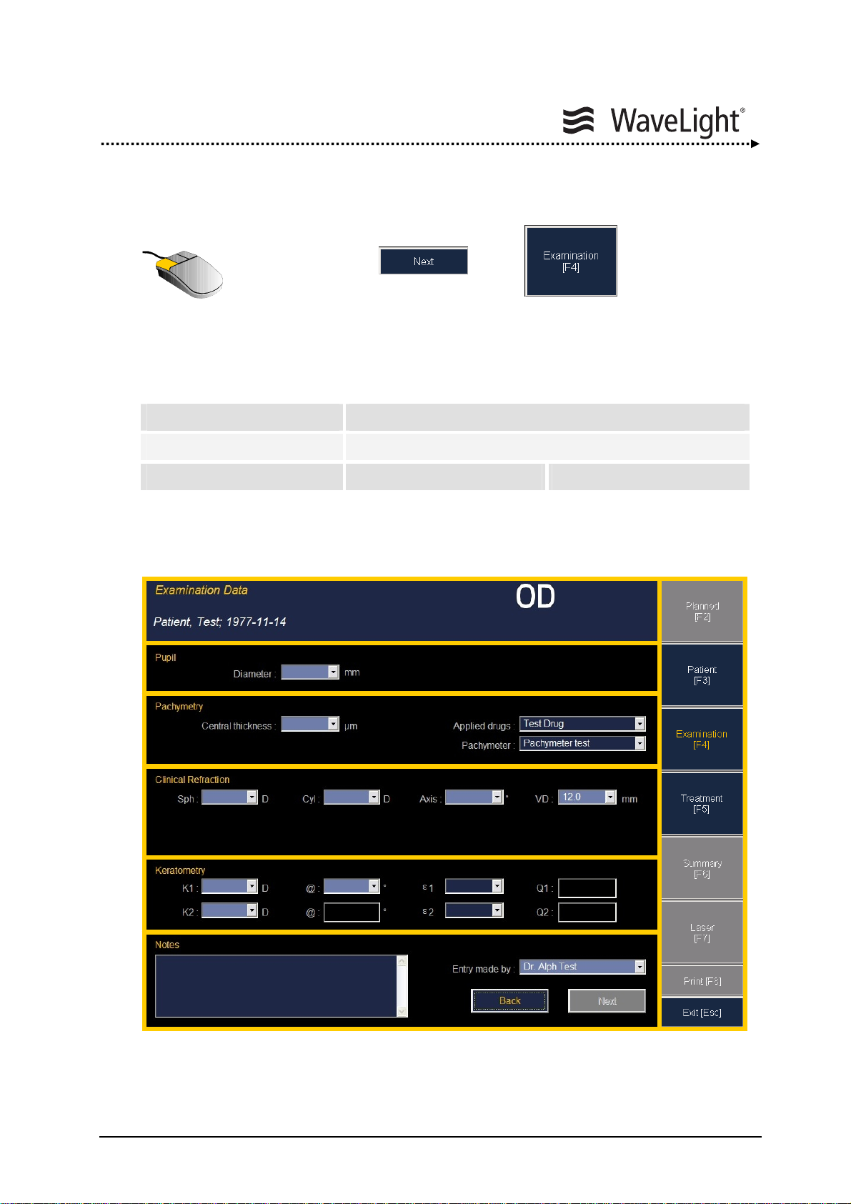
Functional Description
Entering Wavefront Optimized Examination Data:
• Pressing the or the - button the
“Examination Data Window” is shown.
In the “Examination Data Window” the following data can be entered or edited.
This window is divided in seven fields:
1. Patient Data 4. Clinical Refraction Data
2. Pupil Data 5. Keratometry Data (Pre OP Eccentricity)
3. Pachymetry Data 6. Memo 7. Menu Bar
Table 3: Sections Of “Examination Data Window”
Figure 49: Examination Data Window
4
5
6
1
2
3
7
ALLEGRETTO WAVE EYE-Q 1010 User Manual en / Rev.9 / 09-06-08 Item No.: 6638 2001 Page 75 of 232
Page 76

Functional Description
A wrong Vertex Distance leads to wrong corrections, please check this value
carefully.
For the ε1 and ε2 values, only use the ALLEGRO Topolyzer. Please refer to
the Topo-guided User Manual.
Figure 50: Examination Data Window - Example With Data
WARNING
CAUTION
Page 76 of 232 ALLEGRETTO WAVE EYE-Q 1010 User Manual en / Rev.9 / 09-06-08 Item No.: 6638 2001
Page 77

Functional Description
• Fill out all light blue textboxes in the “Examination Data Window”
and check the entries for their correctness. (The dark blue textboxes
are optional).
Pupil
Diameter [mm]
Pachymetry
Central thickness [µm]
Clinical Refraction
SPH [D]
CYL [D]
Axis [°]
VD [mm]
Keratometry
K1 [D]
K2 [D]
@ [°]
Doctor
Table 4: Enter Examination Data
If no treatment data is imported or no ε and Q-value is entered only Wavefront Optimized
and PTK treatments can be selected.
“Vertex Distance” and
“Flap Thickness” as well as
“Applied Drugs” and “Pachymetry”
can be entered as default settings.
Please see chapter
5.6.13 “Enter
Default Settings” on page 121.
• Click the - button or the - button to
confirm the entries.
Or
• click the - button to switch to the patient data.
ALLEGRETTO WAVE EYE-Q 1010 User Manual en / Rev.9 / 09-06-08 Item No.: 6638 2001 Page 77 of 232
Page 78

Functional Description
Entering Wavefront Optimized Treatment Data:
• Pressing the or the - button the
“Treatment Data Window” is shown.
The ablation profile is visualized in the “Treatment Data Window”.
The “Treatment Data Window” is divided in four fields:
1. Patient Data 3. Visualization of the treatment
2. Treatment Data 4. Menu Bar
Table 5: Sections Of “Treatment Data Window”
Nomogram info (see chapter
Figure 51: Treatment Data Window Radius of displayed Ablation depth in µm
circle in mm
Pupil diameter and position during the measurement
1
2
3
5.5.1 “Nomogram” on page 64)
4
Page 78 of 232 ALLEGRETTO WAVE EYE-Q 1010 User Manual en / Rev.9 / 09-06-08 Item No.: 6638 2001
Page 79

Functional Description
Here the treatment type can be changed subsequently.
Set the treatment type to WFoptimized (Wavefront Optimized) and exit the drop-down
box using the TAB-button.
Clinical: shows refractive values entered in Examination Data.
Target: shows refractive target values.
Correction: These values are used for the treatment
(composed from Clinical and Target).
Correction Type: shows differently colored visualization for better determination.
Myopia and Myopic Astigmatism: yellow
Hyperopia and Hyperopic Astigmatism: magenta
Astigmatism and Mixed Astigmatism: white
Check if all data have been entered correctly.
• Enter a target value for sphere and cylinder, if not zero.
• Enter Optical zone
• Enter Flap thickness
An alert will occur, if the calculated remaining stoma thickness is thinner than
the limit that is defined in the setup.
NOTE
ALLEGRETTO WAVE EYE-Q 1010 User Manual en / Rev.9 / 09-06-08 Item No.: 6638 2001 Page 79 of 232
Page 80

Functional Description
Wavefront Optimized Treatment Calculation:
• Now the “Summary Window” can be opened by pressing the
or the - button
• Click the - button to go to the examination data.
The “Summary Window” shows all important data required to start the calculation of the
ablation pattern needed for the treatment.
The “Summary Window” is divided in four fields:
1. Patient Data 3. Treatment Calculation
2. Treatment Data 4. Menu Bar
Table 6: Sections Of “Summary Window”
Figure 52: Summary Window Remaining Stroma “Ablation” depth Treatment method
1
24
3
Page 80 of 232 ALLEGRETTO WAVE EYE-Q 1010 User Manual en / Rev.9 / 09-06-08 Item No.: 6638 2001
Page 81

Functional Description
• Check all treatment data.
• Enter the name of the surgeon in the field marked by SURGEON.
(The name of the surgeon can also be entered as default setting.
Please see chapter
• Enter the name of the examiner in the field CONFIRMED BY
(re-check all treatment data by your assistant for more safety).
• Then, press the - button.
• Click the - button to start the ablation pattern
calculation of the treatment.
A progress bar shows the progress of the calculation.
Figure 53: Summary Window - Calculation In Progress
5.6.13 “Enter Default Settings” on page 121.)
ALLEGRETTO WAVE EYE-Q 1010 User Manual en / Rev.9 / 09-06-08 Item No.: 6638 2001 Page 81 of 232
Page 82

Functional Description
Planned Wavefront Optimized Treatments:
After finishing the calculation the buttons and are
enabled and the treatment is registered
in the “Patient Treatment Field”.
Figure 54: Patient Data Window - Registered Treatment
In the “Treatment Information Field” the treatment
status is displayed.
Page 82 of 232 ALLEGRETTO WAVE EYE-Q 1010 User Manual en / Rev.9 / 09-06-08 Item No.: 6638 2001
Page 83

Functional Description
• Click the - button to see the calculated/planned
treatment patterns in the schedule list “Calculated
Treatments”.
Since only one data set has been imported, confirmed and
calculated a “Planned” data set is displayed.
The “Planned Treatment Window” is divided in three fields:
1. Calculated Treatments 3. Menu Bar
2. Transmitted Treatments
Table 7: Sections Of “Planned Treatment Window”
Figure 55: Planned Treatment Window
1 2 3
ALLEGRETTO WAVE EYE-Q 1010 User Manual en / Rev.9 / 09-06-08 Item No.: 6638 2001 Page 83 of 232
Page 84

Functional Description
• Then select the planned treatment and continue with the
- button. The program switches back to the
“
Summary Window” (see figure 53 on page 81).
To cancel the planned treatment press the - button.
• Press the button in the “Summary Window” and
follow the prompts on the screen.
A data transfer is only possible if the notebook is physically connected with the
ALLEGRETTO WAVE EYE-Q laser and the ALLEGRETTO WAVE EYE-Q
laser device is in the “Standby Mode”. If the data transmission is not
successful the message “Laser Not Ready” will appear.
The calculated data are sent to the ALLEGRETTO WAVE EYE-Q laser.
A progress bar shows this process.
NOTE
Page 84 of 232 ALLEGRETTO WAVE EYE-Q 1010 User Manual en / Rev.9 / 09-06-08 Item No.: 6638 2001
Page 85

Functional Description
Carry Out The Wavefront Optimized Or The Test Treatment:
After the data transfer, a “Popup Window” prompts the user to select between the Testor Treatment Mode.
The Test Mode is to verify the geometry of the ablation profile.
Figure 56: Popup Window - Select Mode
Here you can select between the TEST MODUS and the TREATMENT MODUS.
Test = Perform as many test ablations as desired using the generated treatment pattern,
e.g. on paper or test plates to cross check once more again the result of the ablation
process (ablation geometry). This window can be disabled with the option
in the “
(see chapter
5.6.13 on page 121) such that the Treatment Mode is set as Default Mode.
• Press the - button to start the TEST MODUS
or
• press the - button to start the TREATMENT MODUS.
Setting Menu”/“Enter Default Settings”
ALLEGRETTO WAVE EYE-Q 1010 User Manual en / Rev.9 / 09-06-08 Item No.: 6638 2001 Page 85 of 232
Page 86
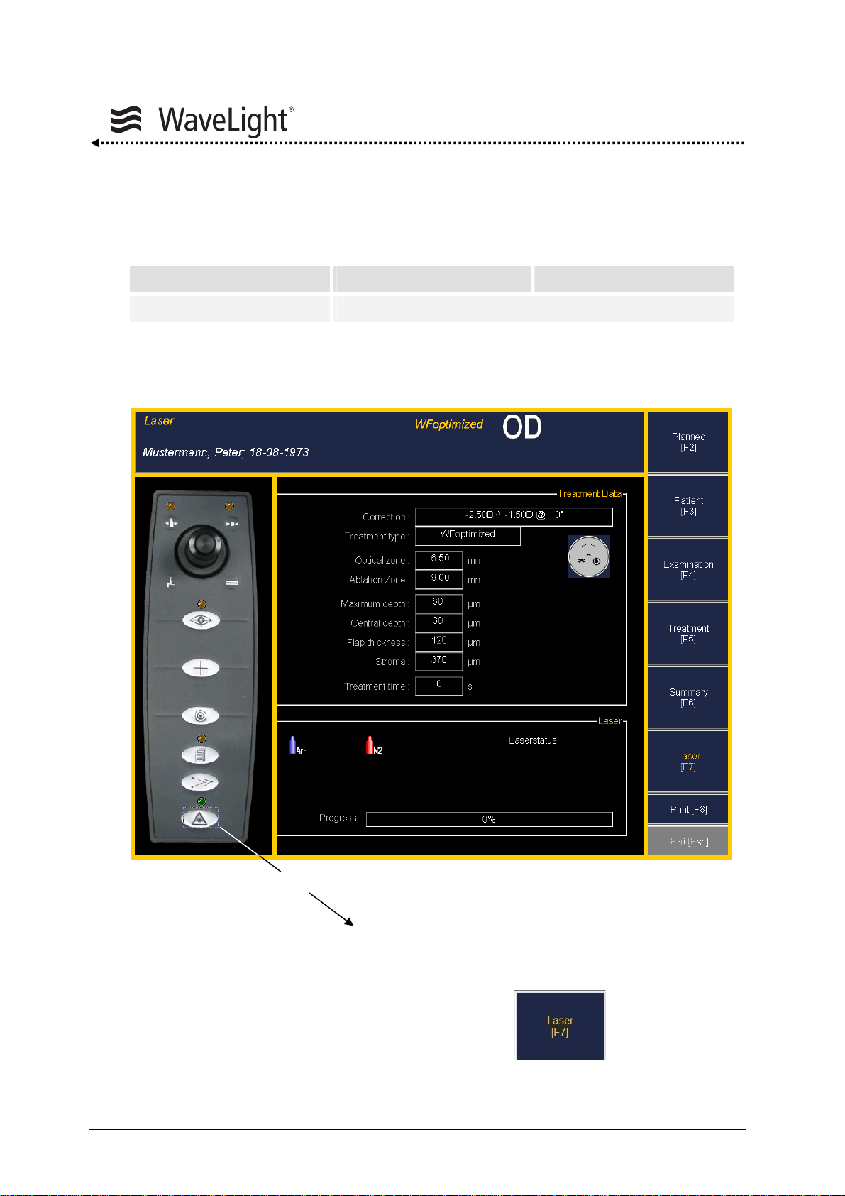
Functional Description
After this the following “Wavefront Optimized Treatment Window” is shown.
It is divided in five fields:
1. Patient Data 3. Treatment Data 5. Menu Bar
2. Laser Panel 4. Laser Status
Table 8: Sections Of “WFoptimized Treatment Window”
Figure 57: ALLEGRETTO WAVE EYE-Q WFoptimized Treatment Window
Ready Key on Laser Panel
If all treatment data are calculated and transferred, the - button is
activated.
2
1
3
4
5
Page 86 of 232 ALLEGRETTO WAVE EYE-Q 1010 User Manual en / Rev.9 / 09-06-08 Item No.: 6638 2001
Page 87

Functional Description
To carry out a treatment on a patient, please refer to the following chapters in
the sequence listed below.
• chapter 5.7 “Positioning The Patient” on page 129.
• chapter 5.8 “Checking The Eyetracker Function” on page 130.
• chapter 5.9 “Hints For Keratectomy” on page 132.
• chapter 5.10 “Ready Mode” on page 133.
• chapter 5.11 “Patient’s Eye Alignment, Fixation And Centering” on
page 134.
• chapter 5.12 “Starting Laser Treatment” on page 136.
All text that appears on the ALLEGRETTO WAVE EYE-Q LCD screen also
appears on the notebook display. The LCD screen of the
ALLEGRETTO WAVE EYE-Q is the master.
In the case of a defective connection between the notebook and the
ALLEGRETTO WAVE EYE-Q, the error message “Laser Not Ready” appears.
In the case of incomplete parameter selection, the error message “Entry
Incomplete” appears.
In the case of unavailable treatment parameters, the error message “Selected
Treatment Not Released” appears on the LCD screen of the
ALLEGRETTO WAVE EYE-Q laser.
Control panel functions of the laser console can be switched by clicking on the
buttons of the control panel display of the “ALLEGRETTO WAVE EYE-Q
Treatment Window”. Default settings should not be changed.
CAUTION
NOTE
ALLEGRETTO WAVE EYE-Q 1010 User Manual en / Rev.9 / 09-06-08 Item No.: 6638 2001 Page 87 of 232
Page 88

Test Treatment:
• Check the eyetracker.
• The laser can now be switched to the “Ready Mode” by moving the cursor to the
• The ALLEGRETTO WAVE EYE-Q will now conduct internal tests.
• If tests are successful the ALLEGRETTO WAVE EYE-Q laser console and the
• Follow the orders on the notebook screen and the LCD display of the laser console.
• The system is now ready to perform a Test treatment.
Functional Description
laser warning symbol and clicking on the left mouse button. Instead of this,
it is also possible to press the “SPACEBAR” on the keyboard of the notebook.
notebook portal software will indicate the “Ready Mode”. The treatment time and a
green Ready Mode indicator will be shown in the “ALLEGRETTO WAVE EYE-Q
Treatment Window”.
To do so, press the LASER pedal. Once the laser ablation has been started, a
progress bar in the laser status field shows the progress of the laser treatment.
Figure 58: ALLEGRETTO WAVE EYE-Q Treatment Window
Page 88 of 232 ALLEGRETTO WAVE EYE-Q 1010 User Manual en / Rev.9 / 09-06-08 Item No.: 6638 2001
Page 89
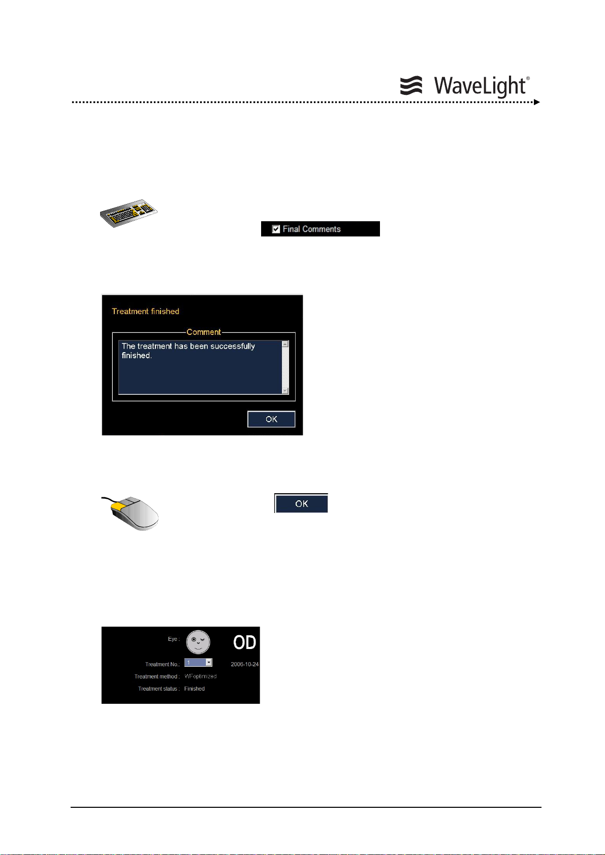
Functional Description
Finish Treatment:
Once the treatment has been completed,
• enter a COMMENT if desired
(The option is selected in the
“
Setting Menu”/“Enter Default Settings”, chapter 5.6.13 on
page 121.)
Figure 59: Popup Window - Final Comments
• and press the - button.
Once this window is closed, the notebook portal software automatically returns to the
“Summary Window” (see figure
most of the buttons will be disabled.
52 “Summary Window” on page 80). Entry boxes and
In the “patient data window” the treatment status is
displayed (see figure
54 “Patient Data Window” on
page 82).
ALLEGRETTO WAVE EYE-Q 1010 User Manual en / Rev.9 / 09-06-08 Item No.: 6638 2001 Page 89 of 232
Page 90

Functional Description
Interrupt Treatment:
If a running treatment is interrupted for more than 10 seconds by leaving the LASER
pedal, a message will pop up. The message will automatically close when you proceed
with the treatment by pressing the LASER pedal again.
Figure 60: Question Window
• Press the - button to continue the treatment
or
• press the LASER pedal again.
• To abort press the - button.
A second window asking for confirmation of abortion will pop up
(see figure
61 “Warning Window” on page 91).
Page 90 of 232 ALLEGRETTO WAVE EYE-Q 1010 User Manual en / Rev.9 / 09-06-08 Item No.: 6638 2001
Page 91
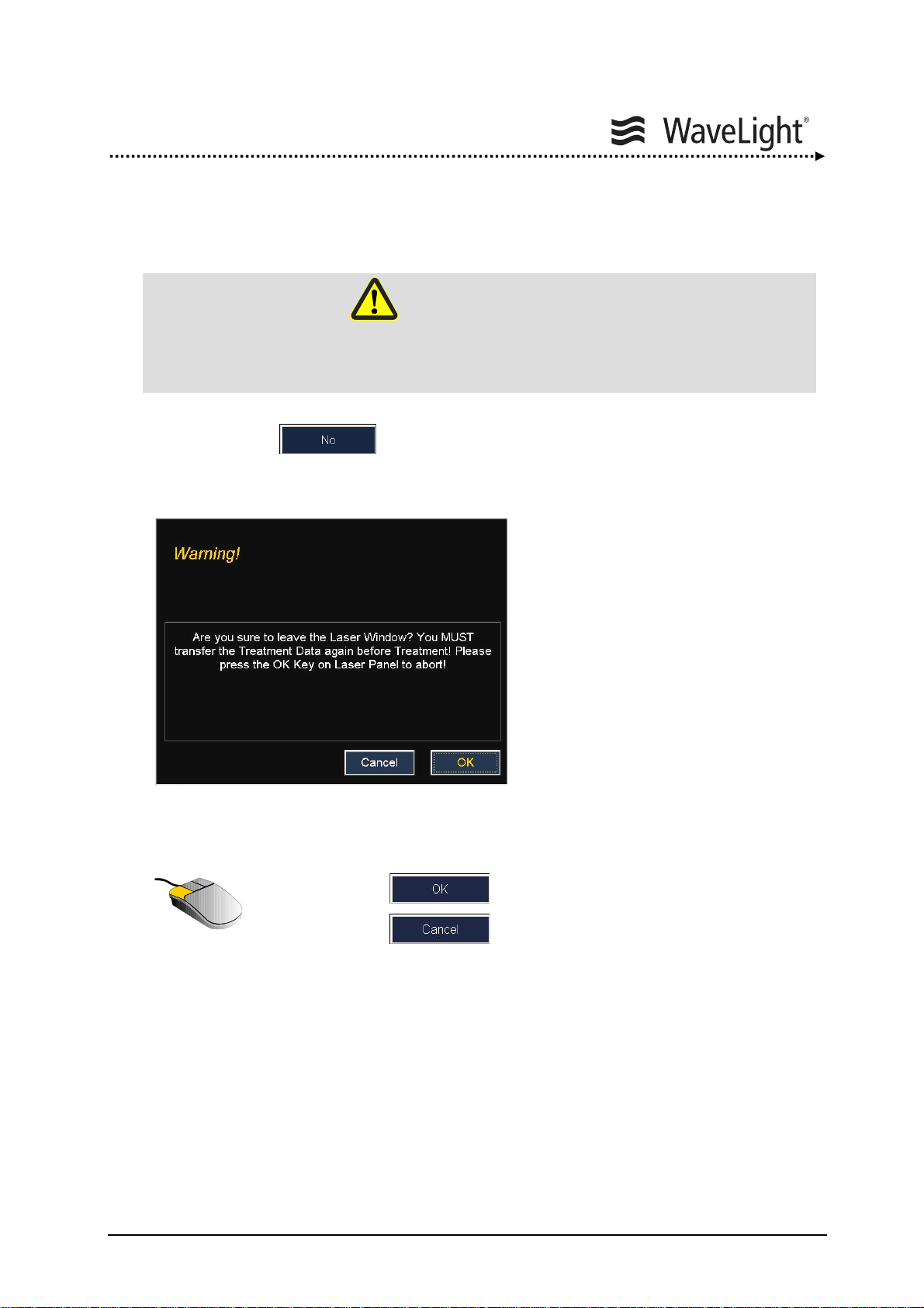
Functional Description
Abort Treatment:
Incomplete Treatment
If you press the - button to abort the treatment, the following window is
displayed.
Figure 61: Warning Window
• Press the - button to transfer the treatment data,
• press the - button to continue the treatment
or
• press the OK Key on the control panel to abort the treatment.
WARNING
ALLEGRETTO WAVE EYE-Q 1010 User Manual en / Rev.9 / 09-06-08 Item No.: 6638 2001 Page 91 of 232
Page 92

5.6.3. Examination Data Range Wavefront Optimized
Figure 62: Examination Data Window - WFoptimized
Min Max Step*
Functional Description
Pupil diameter
Pachymetry corneal
thickness
SPH
CYL
AXIS
VD
K1
K2
@
ε1
ε2
* If data are transferred from the ALLEGRO Analyzer, the step-values can vary. The treatment range
depends also from the used treatment list. Only the released treatment lists can be selected.
Table 9: Examination Data Range - WFoptimized
Page 92 of 232 ALLEGRETTO WAVE EYE-Q 1010 User Manual en / Rev.9 / 09-06-08 Item No.: 6638 2001
mm 1.00 9.00 0.01
µm 200 700 1
D - 14.00 + 6.00 0.01
D - 10.00 + 6.00 0.01
° 0 180 1
mm 0 30 0.1
D 30 60 0.01
D ≥ K1 60 0.01
° 0 180 1
- 1.00 1.00 0.01
- 1.00 1.00 0.01
Page 93

Functional Description
5.6.4. Treatment Data Range Wavefront Optimized
The table below shows the variable fields and ranges which can be adjusted between
the minimum and maximum values.
Figure 63: Visualization Window - WFoptimized
Min Max Step
SPH target *
CYL target *
Optical zone
Flap thickness
* Starting from the entered clinical refraction.
** No 7.5 mm optical zone
D - 3 + 3 0.25
D - 3 + 3 0.25
mm 4.50 8.00 0.50**
µm 0 200 1
Table 10: Treatment Data Range - WFoptimized
ALLEGRETTO WAVE EYE-Q 1010 User Manual en / Rev.9 / 09-06-08 Item No.: 6638 2001 Page 93 of 232
Page 94
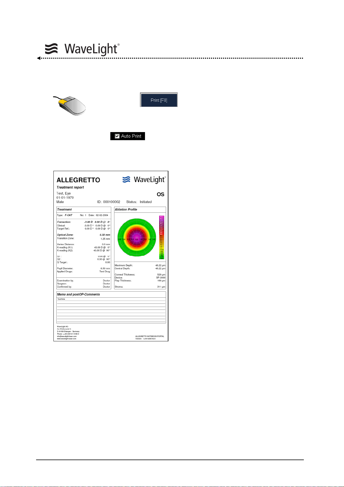
5.6.5. Printout
Functional Description
• Press the - button to print out the treatment and
patient data.
If you prefer to get the printout automatically, please activate the
function.
Please refer to chapter
Figure 64: Example For A Printout
5.6.13 “Enter Default Settings” on page 121.
Page 94 of 232 ALLEGRETTO WAVE EYE-Q 1010 User Manual en / Rev.9 / 09-06-08 Item No.: 6638 2001
Page 95

Functional Description
5.6.6. Screenshot
To perform a screenshot insert a USB-stick into the USB-port
(see also figure
The current screen is saved as jpeg-file.
Please also see section “
77 on page 113).
• Then press CTRL + P
USB-stick Deactivation” on page 117.
ALLEGRETTO WAVE EYE-Q 1010 User Manual en / Rev.9 / 09-06-08 Item No.: 6638 2001 Page 95 of 232
Page 96

5.6.7. How To Perform a PTK Treatment
Entering Patient Data:
• Either select a patient from the treatment list or create a new one.
For creating a new patient click the - button.
If the patient already exists a “Popup Window” asks to create a new
ID.
• Now enter the patient’s personal data,
• select the eye you wish to treat
• and click the - button or the - button.
For detailed information please refer to chapter
Notebook Portal Software” / section “
Figure 65: Patient Data Window
Entering Patient Data” on page 73.
Functional Description
5.6 “Navigation And Data Entry With The
Page 96 of 232 ALLEGRETTO WAVE EYE-Q 1010 User Manual en / Rev.9 / 09-06-08 Item No.: 6638 2001
Page 97

Functional Description
Entering PTK Examination Data:
The following data can be entered or edited in the “Examination Data Window”.
PTK = Photo-Therapeutic-Keratectomy
This function has no refractive influence on the cornea, therefore “0” can be specified for
the sphere, cylinder and axis.
Figure 66: Examination Data Window “PTK” - Example With Data
For the ε1 and ε2 values, only use the ALLEGRO Topolyzer. Please refer to
the Topo-guided User Manual.
CAUTION
ALLEGRETTO WAVE EYE-Q 1010 User Manual en / Rev.9 / 09-06-08 Item No.: 6638 2001 Page 97 of 232
Page 98
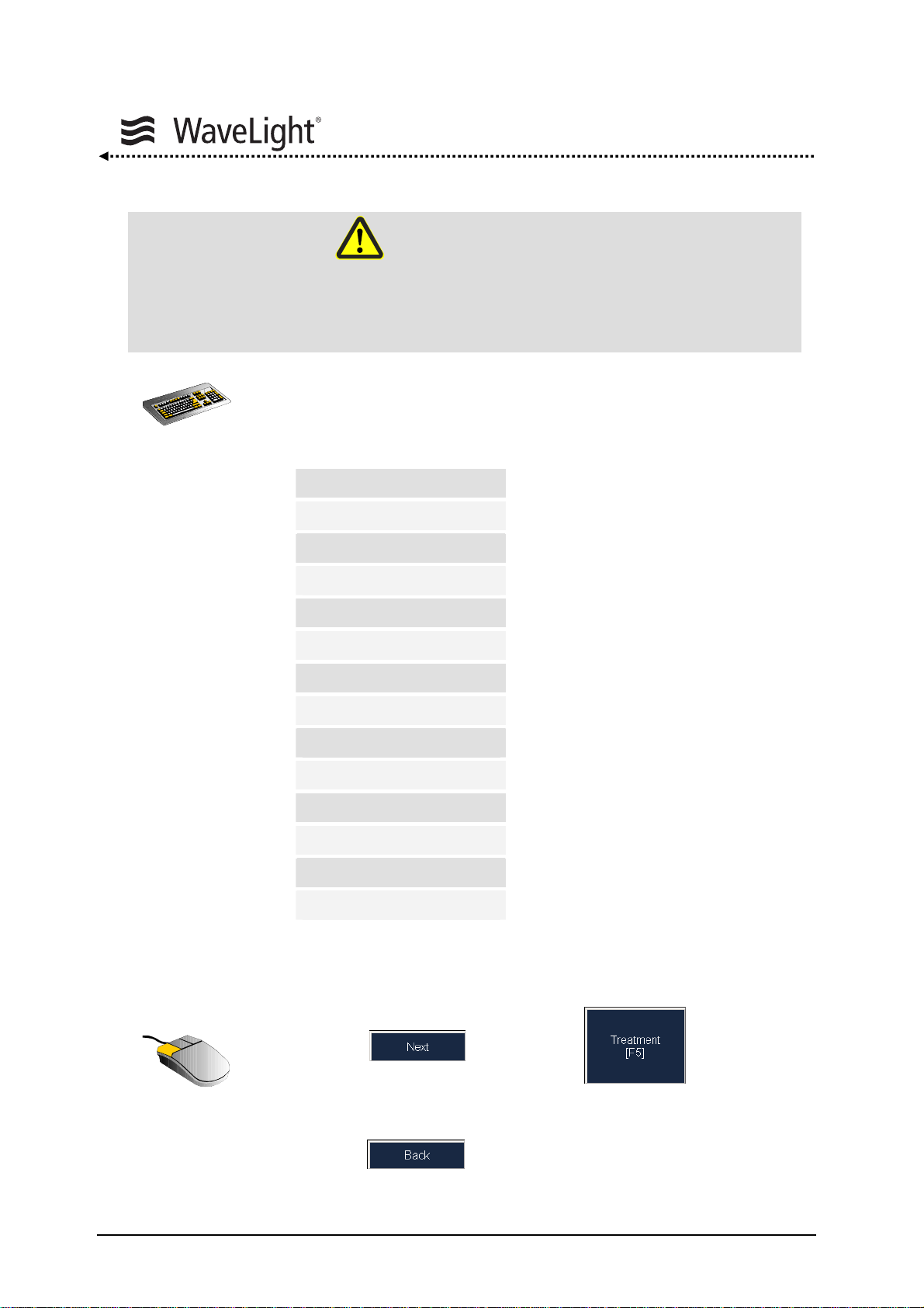
Functional Description
WARNING
A wrong Vertex Distance leads to wrong corrections, please check this value
carefully.
• Fill out all light blue textboxes and check the entries for their
correctness. (The dark blue textboxes can be filled out optionally).
Pupil
Diameter [mm]
Pachymetry
Central thickness [µm]
Clinical Refraction
SPH [D]
CYL [D]
Axis [°]
VD [mm]
Keratometry
K1 [D]
K2 [D]
@ [°]
Doctor
Table 11: Enter Examination Data
• Click the - button or the - button to
confirm the entries.
Or
• click the - button to switch to the patient data.
Page 98 of 232 ALLEGRETTO WAVE EYE-Q 1010 User Manual en / Rev.9 / 09-06-08 Item No.: 6638 2001
Page 99

Functional Description
Entering PTK Treatment Data:
Figure 67: Warning Message In The Treatment Data Window
Check if all data have been entered correctly.
• Enter Optical zone
• Enter Ablations depth
• Enter Flap thickness
If an entry is missing or not valid, a warning message is displayed (see figure
67 above).
ALLEGRETTO WAVE EYE-Q 1010 User Manual en / Rev.9 / 09-06-08 Item No.: 6638 2001 Page 99 of 232
Page 100
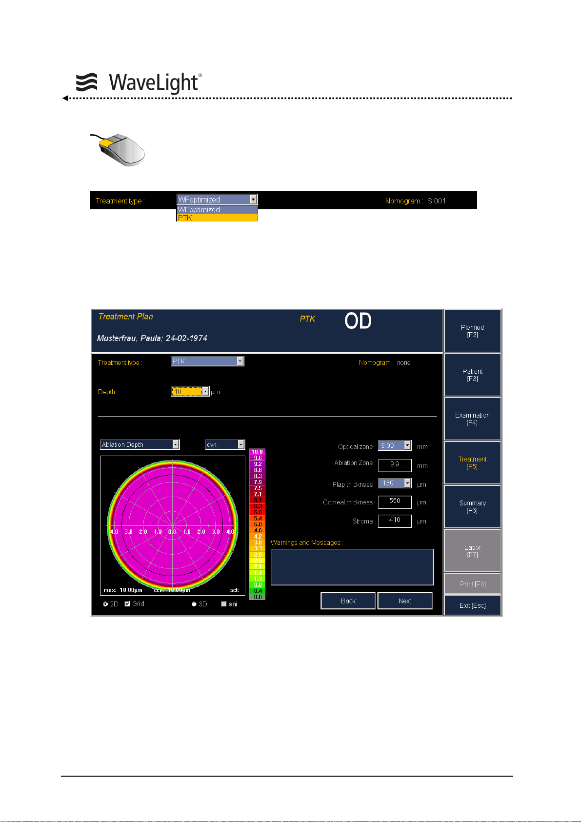
Functional Description
• Set the treatment type to PTK and exit the drop-down box using the
TAB-button.
The program switches to the “PTK Treatment Data Window”. The ablation profile is
visualized.
Figure 68: Treatment Data Window - PTK
Page 100 of 232 ALLEGRETTO WAVE EYE-Q 1010 User Manual en / Rev.9 / 09-06-08 Item No.: 6638 2001
 Loading...