

Page 1

Installation Instructions
™
Excelevator
Elevator
Series 114
1726 North Ballard Road, Suite 1 • Appleton, WI 54911
Phone 920-991-9082 • Fax 920-991-9087
Technical Support 855-804-5774
www.waupacaelevator.com
PMI114-V
30 March 2018
950/1,000 lbs.
Page 2

Page 3
Installation Table of Contents
General Information
Series 114
Description ....................................................................P a g e
General Information ................................................................................4
Warning and Safety Label Install......................................................... 5
Factory Installed Warning & Safety Label Installation ...............6
Hyrdaulic Elevator Recommended Tool List .................................7
Return Material Authorization ..................... ........................................8
Troubleshooting with Tech Support...................................................9
Hoistway Dimensions ..................................... ...................................10
Conversion Rail Bracket Installation .......... ...................................11- 12
Rail Bracket Installation .................................. ......................................13
Rail and Pedestal Installation ....................... ......................................14
Two Piece Jack Assembly .....................................................................15
Jack Installation ................................................. ......................................16
Ram’s Header Installation ....................................................................17
Controller Installation and Wiring ............. ..................................18 -19
GMV/OLS Hydraulic Power Unit Installation ..............................20
Final Limit Installation .........................................................................21
Pendant Control .....................................................................................22
Piston Projection....................................................................................23
Sling Installation ............................................... ................................24-25
Sling Extension Installation ..........................................................26-27
Proper Handling of Wire Rope............................................................ 28
Wire Rope Installation ................................................................29-31
Verify Jack Travel ................................................................................32
Car Operating Panel Installation ................. .................................33
Wall Mount Telephone Jack .......................... .................................34
Handrail Installation ........................................ .................................35
Framlees Car Assembly .................................. ..........................36-38
Stabilizer Bracket Installation ....................... .................................39
Steel Tape Installation ..................................... ...................................40
Description ............................................ ..................... ..P a g e
Slack Rope Safety Wiring.............................................................41
Modular Wiring Car Top Layout ........................................................42
Emergency Light Installation and Fuse Installation................43
Car Top Modular Wiring ..................................................................44
Tape Reader Driver Board ..............................................................45
LED Light Installation .........................................................................46
LED Light Wiring (without battery backup)..................47
LED Light Wiring (without battery backup wiring) ............48
Accordion Gate Installation .......................... ..............................49-50
Frameless Car Gate Switch ........................... ....................................52
Travel Cable Installation ................................. ...................................53
Travel Cable to Controller Wiring............................. .............................54
Hoistway Wiring Layout .....................................................................55
Hall Station Wiring & Installation ................ ...................................56
Stop Pit Switch Installation ........................... ......................................57
EMI & GAL Magnet Placement 6 Stop.............................................. 58
Toe Guard Installation ..................................... ....................................59
Automatic Operation ...........................................................................60
GMV/OLS Microprocessor Inputs and Outputs ...........................61
Programs & POT Settings ............................................................62-63
Auto Gate Program .......................................... ....................................64
Valve Adjustments ........................................... ..............................65-67
Troubleshooting ..................................................................................68-69
Troubleshooting PLC Inputs and Output.................................70-71
Troubleshooting Controller Layout ........... ....................................72
Semi- Annual General Maintence Chart ..................................73
Semi- Annual Maintence Messages ........... ................................74
Elevator Release Checklist......................................... ........................75
PMI114-TC-V
30 MAR 2018
1726 North Ballard Road, Suite 1 - Appleton, WI 54911 - 920.991.9082
Technical Support 855.804.5774 - [email protected]
W
E
Page 4
GENERAL INFORMATION
Page 4
Ethical Standards
Waupaca Elevator Company subscribes to the ACCESSIBILITY EQUIPMENT MANUFACTURERS ASSOCIATION
(AEMA) Code of Ethical Practices:
Be it resolved that we will conduct our business a airs in such a manner that they will be fair to all parties concerned.
• And further resolved, that we will manufacture and/
or distribute only products which re ect good quality,
safety and the best engineering practices for any given
application.
• And further resolved, that we will respect our competitors
deserving of our respect.
• And further resolved, that we will refrain from being
derogatory.
Introduction
Installation should be done by a trained authorized
Elevator Contractor in accordance with these
instructions and in compliance with requirements
of National Elevator Code, National Electrical Code,
American Standard Safety Code, and State and
Local Building Codes.
This manual is designed as a guide to the installation
and maintenance of this Waupaca Elevator unit. The
instructions are designed to help ensure the safe
installation and operation of this unit. Read them
carefully before beginning installation.
Inspect for visible signs of damage or missing parts
BEFORE beginning installation. The nal check list
indicates all components included with this order.
Work by others to include, but not limited to, the
hoistway construction, supports for guide rails and an
electrical fused disconnect to control panel.
Do not expose electrical components to the elements or
extreme temperature uctuations. Resulting condensation will damage equipment, causing it to malfunction. If
exposed, let sit for 12-24 hours prior to operation.
Safe operation requires a maintained hoistway
and mechanical room temperature between 60° F
to 110° F.
• And further resolved, that we will not take unfair advantage of our dealers.
• And further resolved, that we will always uphold the high
standards and the purposes of AEMA.
• And further resolved, that we will refuse to be party to
any of the following: price xing, collusion monopoly,
non-code compliance, deviation from speci cations after
quoting, and knowingly endorsing members of this or
any other trade association if they are not quali ed or are
known to be unethical or dishonest.
Illustration Noti cation
For purposes of visual clari cation, some parts have been
omitted from certain illustrations.
Illustrations are of typical parts and may not match your
materials exactly.
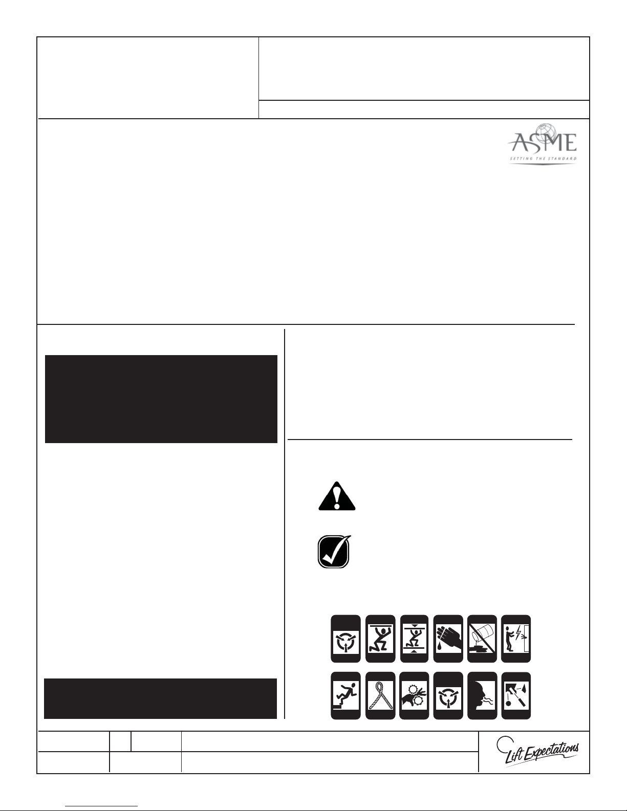
Safety Alerts
Danger!
Indicates a condition where failure to follow
exact instructions or heed warnings may result
in equipment damage, personal injury or death.
Important
Indicates critical information that should be
reviewed carefully.
These symbols will remind you of potential injury.
General Reminders
ANTI-
STATIC
ALERT
FALLING
HAZARD
CRUSH
CRUSH
HAZARD
HAZARD
KINK
CRUSH
HAZARD
HAZARD
CRUSH
CRUSH
HAZARD
HAZARD
PINCH
CRUSH
HAZARD
HAZARD
CUTTING
CRUSH
HAZARD
HAZARD
STATIC
ELECTRICITY
HAZARD
ECO-SYSTEM
HAZARD
INHALATION
HAZARD
ELECTRIC
HAZARD
MISSILE
HAZARD
PM0010-B
25 OCT 2017
1726 North Ballard Road, Suite 1 - Appleton, WI 54911 - 920.991.9082
Technical Support 855.804.5774 - [email protected]
W
E
Page 5
WARNING & SAFETY
Page 5
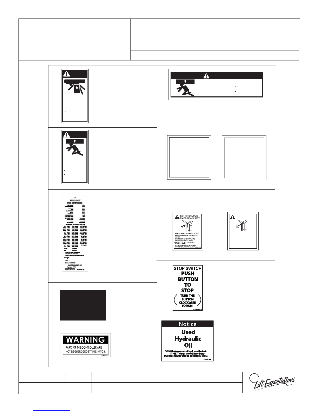
LABEL INSTALLATION
SERIES : 114 ,116
DANGER
Elevator car can
come up and crush
you to death!
Before entering this area:
Pull Emergency Stop
Use a 4 foot brace on
top of car
L-006435-A
DANGER
Elevator car can
come down and
crush you to death!
Before entering this area:
Pull Emergency Stop
Use a 4 foot brace to
support car
L-006381-A
(1) To front
wall in the
overhead of
hoistway.
(1) On top of
elevator car.
(1) To hoistway
wall 3’ above
pit facing door.
(1) On the Jack
Wire Rope Tag
(1) To the wire
rope where it
will not interfere
with elevator
operations.
(Tag may vary
due to supplier.)
DANGER
Elevator car can
come down and
crush you to death!
(1-3) Center in opening/s on toe guard
(1) To the inside of cab
(manual gate only)
OPERATING INSTRUCTIONS
FOR WAUPACA ELEVATOR WITH MANUAL GATE
1. Close hoistway door and close elevator gate.
2. If keylock is provided, insert key in lock and turn to “ON”.
3. Press desired oor on the car operating panel.
4. Once stopped at landing open gate.
5. Open door and exit elevator.
6. Close the gate.
7. Securely close hoistway door.
8. Should elevator fail to operate.
-Verify gate and hoistway door are fully closed.
-If keylock equipped, verify key is in the “ON” position
-Verify that the emergency stop button is pushed in.
9. Do not load elevator beyond its rated capacity.
10. Do not open gate while elevator is in motion.
11. Keep all body parts inside the elevator car at all times.
IF ELEVATOR STOPS BETWEEN FLOORS WAIT 7 SECONDS AND TRY TO
RETURN TO FLOOR THAT YOU C AME FROM, IF YOU REMAIN STUCK PRESS
ALARM BUTTON TO GET ASSISTANCE IN THE HOUSE OR USE PHONE TO
GET ASSISTANCE.
DO NOT ATTEMPT TO REPAIR THIS ELEVATOR YOURSELF.
CALL DEALER FOR SERVICE OR AN ELEVATOR SERVING COMPANY
DO NOT REMOVE OR COVER THIS SIGN.
L-006432-B
(1) To the inside of cab
(automatic gate only)
OPERATING INSTRUCTIONS
FOR WAUPACA ELEVATOR WITH AUTOMATIC GATE
1. Close hoistway door and the elevator gate will automatically close.
2. If keylock is provided, insert key in lock and turn to “ON”.
3. Press desired oor on the car operating panel.
4. Once stopped at landing the gate will automatically open.
5. Open door and exit elevator.
6. Securely close hoistway door.
7. Should elevator fail to operate:
- Verify gate and hoistway door are fully closed.
- If keylock equipped, verify key is in the “ON” position.
- Verify that the emergency stop button is pushed in.
8. Do not load elevator beyond its rated capacity.
9. Do not open gate while elevator is in motion.
10. Keep all body parts inside the elevator car at all times.
IF ELEVATOR STOPS BETWEEN FLOORS WAIT 7 SECONDS AND TRY TO
RETURN TO FLOOR THAT YOU CAME FROM, IF YOU REMAIN STUCK PRESS
ALARM BUTTON TO GET ASSISTANCE IN THE HOUSE OR USE PHONE TO
DO NOT ATTEMPT TO REPAIR THIS ELEVATOR YOURSELF.
CALL DEALER FOR SERVICE OR ELEVATOR SERVICING COMPANY
(1) To controller face next to
emergency key holding bracket.
or
(EMI interlock)
- SWITCH MAIN DISCONNECT TO "OFF"
- REMOVE KEY FROM CONTROL BOX
COVER
- INSERT KEY IN KEYWAY UNTIL HANDLE
CONTACTS INTERLOCK
- GENTLY TURN KEY TO RELEASE
INTERLOCK
- SLOWLY OPEN HOISTWAY DOOR WITH
INTERLOCK RELEASED
(GAL interlock)
Before entering this area:
Pull Emergency Stop
Use a 4 foot brace to
support car
DO NOT REMOVE OR COVER THIS SIGN.
GAL INTERLOCK
EMERGENCY KEY
GET ASSISTANCE.
L-006428-A
GAL
LOCK
L-006427-A
L-006434-B
NON-LOAD
BEARING
SURFACE
PTS70014-J
29 MAR 2018
L-007722-A
(1-3) Place label right next
to the pit stop switch in
(2) Place label on the
ceiling exterior of
the elevator car.
Label must be visible
from opening
(1) Place the label
facing toward the
hoistway shaft on the
(2) Placed on the
disconnects
plastic container that
catches the oil in the
110V & 240V
1726 North Ballard Road, Suite 1 - Appleton, WI 54911 - 920.991.9082
Technical Support 855.804.5774 - [email protected]
the hoistway pit
hoistway.
W
E
Page 6
T
T
1
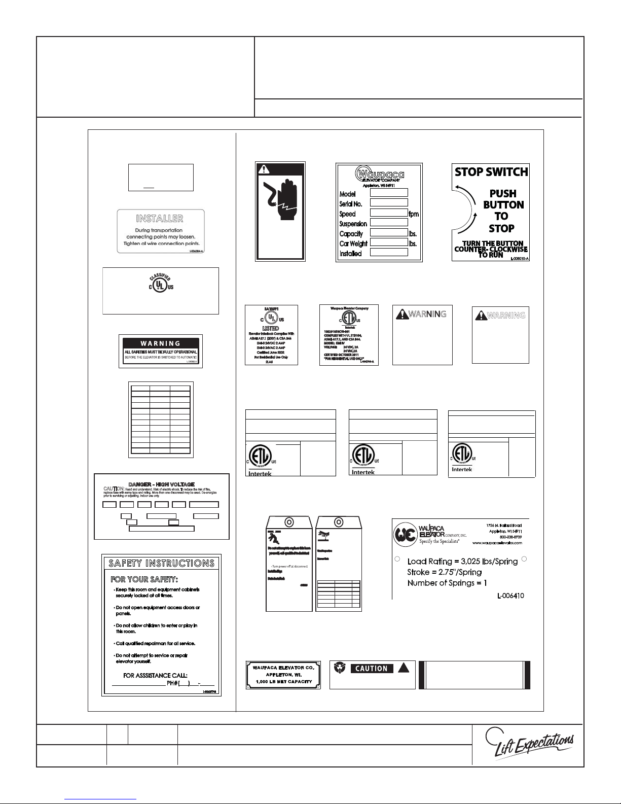
FACTORY INSTALLED
Page 6
WARNING & SAFETY
LABEL INSTALLATION
SERIES : 114 ,116
IN OR ON CONTROLLER
WARNING
For Continued Protection Against Risk of Fire,
Replace with same Type and Rating of Fuse.
AMP, Time Delay
L-006383-A
WAUPACA ELEVATOR INC.
ENCLOSED ELEVATOR CONTROL PANEL
E180739
"As to electrical, shock and re hazard, and in accordance with
L-006406-C
CAUTION:
replace fuse with same type and rating. More than one disconnect may be used. De-energize
prior to servicing or adjusting. Indoor use only.
Voltage (V): Freq. (Hz): Phase (Ø): Wiring Diagram #:HP: Current (A):
Enclosure Type: UL File:
Short Circuit Current: KA rms symmetrical at V maximum
Serial #:
XXXXXX
ASME A17.5-2014 and CAN / CSA B44.1-2014"
FUSE VALUE TYPE
L-006405-A
DANGER - HIGH VOLTAGE
Read and understand. Risk of electric shock. To reduce the risk of fire,
Plant Location:
L-006385-B
ALARM BELL &
CONTROLLER
WARNING
Hazardous voltage
can shock, burn or
cause death.
Do not enter or
service yourself.
Call a qualied repairman.
L-006392-A
EMI III AC & DC
SCREW DRIVE
GATE OPERATOR
WARNING : MORE THAN ONE LIVE CIRCUIT.
SEE DIAGRAM.
AVERTISSEMENT . CET ÉQUIPEMENT
RENFERME PLUSIEURS CIRCUITS SOUS
TENSION. VOIR LE SCHÉMA.
Overload protection is 150 % of full load current ( Fuse on board)
his unit does not incorporate overspeed protection
File: 100104201CHI-001
Screw Drive
ASME A17.5
Gate Operator
CAN/CSA B44.1
120V, 3A, 60Hz
HYDRAULIC HOSE
Elevator car can come
down and can cause
SEVERE INJURY or DEATH
Do not attempt to replace this hose
Before disconnecting hose:
• Secure car and sling
Installed by:
______________________________
Date Installed:
______________________________
PER ASME A17.1: REPLACE HOSE EVERY 6 YEARS OR
SOONER IF REQUIRED BY LOCAL JURISDICTION
Minimum Bend Radius: 4.80 in.
Factory Test Pressure: 3700 PSI
Factory Test Date: _______________
L-006430-B
POWER UNIT
EMI IV AC & DC
Waupaca Elevator Company
Intertek
100291858CHI-001
COMPLIES WITH UL STD104,
ASME-A17.1, AND CSA B44.
MODEL: EMI IV
VOLTAGE: 24 VDC, 2A
24 VAC,2A
CERTIFIED OCTOBER 2011
"FOR RESIDENTIAL USE ONLY"
WARNING : MORE THAN ONE LIVE CIRCUIT.
Overload protection is 150 % of full load current (
L-006469-A
High pressure hydraulic
lines, keep hands clear
while pressure testing
Inspection of hose to occur annually, or as
directed by local jurisdiction
Visual Inspection:
Check for weeping, leakage, kinks, twists, crushed
sections, or damage to outer covering
Pressure Test:
Run unit upward until stop ring is engaged and
pressure relief valve activates. Continue to run
pump for 30 seconds while checking for:
• Leakage
• Slippage of Fittings
• Exposure of Inner Reinforcement
• Bulging/Distortions of Hose Body
COMPANY: TECHNICIAN: DATE:
L-006430-B
WARNING
GATE SWITCH BYP ASS
AND/OR GATE REMOV AL
IS PROHIBITED BY CODE.
SERIOUS INJURY OR
L-006700-A
DEATH COULD RESUL T.
BELT DRIVE
GATE OPERATOR
SEE DIAGRAM.
AVERTISSEMENT . CET ÉQUIPEMENT
RENFERME PLUSIEURS CIRCUITS SOUS
TENSION. VOIR LE SCHÉMA.
his unit does not incorporate overspeed protection
File: 100104201CHI-001
ASME A17.5
Gate Operator
CAN/CSA B44.1
120V, 3A, 60Hz
GATE
L-006416-A
WARNING : MORE THAN ONE LIVE CIRCUIT.
AVERTISSEMENT . CET ÉQUIPEMENT
Fuse on board)
Belt Drive
L-006470-A
RENFERME PLUSIEURS CIRCUITS SOUS
File: 102879262CHI-00
4000929
BUFFER SPRING TAGS
(1) PER BUFFER SPRING
®
CARTOP
EMI AC & DC
WARNING
INTERLOCK BYPASS
AND/OR REMOVAL IS
PROHIBITED BY CODE.
SERIOUS INJURY OR
DEATH COULD RESULT.
CARTOP
SEE DIAGRAM.
TENSION. VOIR LE SCHÉMA.
Copper conductors only!
CONFORMS TO ASME STD A17.5
CERTIFIED TO CAN/CSA STD B44.1
L-006380-A
Waupaca Elevator
Cartop Box
Elevator
120V, 10a, 60Hz
L-007881
PTS70014-J
29 MAR 2018
ALARM BELL &
CAPACITY TAG
MAY VA RY
TAPE READER
Electrostatic sensitive devices within.
Observe anti-static precautions.
NO LIFT - NO STEP
L-006394-A
1726 North Ballard Road, Suite 1 - Appleton, WI 54911 - 920.991.9082
Technical Support 855.804.5774 - [email protected]
CARTOP
CAUTION
W
L-006413-A
E
Page 7
HYDRAULIC ELEVATOR
Page 7
RECOMMENDED TOOL
LIST
SERIES : 114, 116
Safety Equipment
□ Hard Hat
□ Safety Glasses
□ Steel Toe Boots
□ Heavy Gloves
□ Fall Protection Equipment
Power Tools
□ 3/8” Cordless Drill & Drill Bits
□ 1/2” Hammer Drill & Drill Bits
□ Shop Vac
□ Extension Power Cord
□ Reciprocating Saw (Sawzall)
Electrical Wiring Tools & Supplies
□ Wire Crimper
□ Wire Marker Tape
□ Wire Stripper
□ Multi-Meter
□ Clamp on Ammeter
□ Appropriate Fuses
(see controller schematic)
□ WEC Pendant
Measuring Tools
□ 2’ Level
□ 4’ Level
□ 6’ Level
□ Laser Level
□ 25’ Tape Measure
□ Chalk Line
□ Framing Square
□ Plumb Line
□ Calipers
Hand Tools
□ Socket & Wrench Set
□ Allen Wrenches SAE & Metric
□ Utility Knife
□ Cable Cutter
□ File Set
□ Flashlight
□ Needlenose Pliers
□ Rubber Mallet
□ Hack Saw
□ Scissors
□ Set of Screw Drivers ( at & Phillips)
□ Vise Grips
□ Wall Board Roll Lifter
□ Pre-set Interchangeable Head Torque
Wrench Box End Style & Socket Style
(up to 125 ft. lbs. plus)
□ Clamps
□ Spanner Wrench (142 mm, Pin Dia. 8mm)
□ Torque Wrench/Screw Driver
Miscellaneous Equipment & Supplies
□ Ladder and Planks
□ Material to Close O Hoistway
□ Chain Hoist
□ All Purpose Grease
□ Wood Glue
□ Para n Wax
□ Temporary Supports for car
□ Thread Locker
□ Rags or Toweling
Hydraulic Equipment & Supplies
□ Mineral Spirits
□ Hydraulic Oil
□ PTFE Thread Tape
□ PTFE Thread Paste
PTS70018-C
29 MAR 2018
1726 North Ballard Road, Suite 1 - Appleton, WI 54911 - 920.991.9082
Technical Support 855.804.5774 - [email protected]
W
E
Page 8
RETURN MATERIAL
Page 8
AUTHORIZATION
PROGRAM - RMA
1. An RMA Number must be issued at the time the part is ordered, not after the fact, for all CREDIT and
WARRANTY parts returns.
2. When placing an RMA order, speci c information will be required as follows:
a) UNIT’S SERIAL NUMBER
b) part number (if available)
c) exact description of the problem
d) date of manufacture
Have this information ready when you call to expedite the process!
3. All returns must be clearly marked with the assigned RMA number on the outside of the container.
4. No item will be accepted without an RMA number.
5. Outbound Material RMA will be sent out UPS/FEDEX Ground.
6. Any additional shipping costs will be at the dealer’s expense.
7. Absolutely no returns will be accepted after 45 days. All RMA’s have a 45-day open date for receipt by
Waupaca Elevator.
SERIES : ALL
8. All replacement part orders will be invoiced upon shipping and will not be credited until the original
part(s) have been returned to the factory prepaid (no C.O.D.’s will be accepted).
a) Credit will be issued if evaluation proves components or to have failed within our
warranty period.
b) Credit will not be issued if the parts have been installed improperly or misused.
8. Any electrical items returned in proper working condition will be returned to the dealer at the dealer’s expense.
9. Waupaca Elevator reserves the right to deny credit.
10. Some parts may be subject to a 20% restock fee.
11. ALL PARTS HAVE A 90 DAY WARRANTY.
12. We encourage your cooperation with this policy as it will further expedite warranty replacement, better track
returns and allow us to adjust your account in a timely and accurate manner.
To Contact Waupaca Elevator Technical Support
Please Call: 855-804-5774
or
E-mail: [email protected]
PTS70004-E
09 OCT 2017
1726 North Ballard Road, Suite 1 - Appleton, WI 54911 - 920.991.9082
Technical Support 855.804.5774 - [email protected]
W
E
Page 9
TROUBLESHOOTING WITH
Page 9
TECHNICAL SUPPORT
Having the following items on hand will make the troubleshooting
process easier and quicker.
Must Have
1. Serial Number of the unit
2. Multimeter
3. Wire Stripper
4. 1/8” Flat Screwdriver
5. Flashlight
6. Wiring Diagram for the unit
Other Suggested Items
1. WEC Pendant
2. Note pad
3. Writing Utensil
4. Fuses
5. Socket set SAE and Metric
6. Wrench Set SAE and Metric
7. Allen Wrenches SAE and Metric
8. Clamp on Ammeter
9. Rags and Oil Dry
CRUSH
HAZARD
CRUSH
HAZARD
CUTTING
CRUSH
HAZARD
HAZARD
Series: ALL
ECO-SYSTEM
HAZARD
ELECTRIC
HAZARD
FALLING
HAZARD
INHALATION
HAZARD
KINK
CRUSH
HAZARD
HAZARD
PINCH
CRUSH
HAZARD
HAZARD
STATIC
ELECTRICITY
HAZARD
Troubleshooting Tips
1. Take notes as you troubleshoot for future reference.
2. Visually inspect component(s).
3. Check for loose wires and broken contacts.
4. Be familiar with your multimeter.
5. When testing fuses take them out of the circuit (failure to do so may result in a false reading).
6. When checking for voltage do not check to ground
For Technical Support Call : 1-855-804-5774
PTS70009-E
31 JULY 2017
1726 North Ballard Road, Suite 1 - Appleton, WI 54911 - 920.991.9082
Technical Support 855.804.5774 - [email protected]
W
E
Page 10
Hoistway Dimensions
Page 10
SERIES: ALL
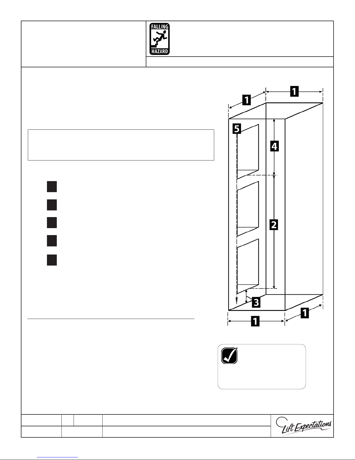
Hoistway Dimensions
Hoistway must be plumb, square and have no
dimension greater than 1” or less than 1/2” as
compared to the hoistway layout drawings.
Note: The use of a laser level is recommended for verifying
the hoistway dimensions and for locating and
marking the center line during rail bracket installation.
Verify the following with your eld drawings:
Hoistway dimensions
1
Total travel
2
Pit depth
3
4
Clear overhead
Doorways are In-Line
5
Rail Backing
6
Chain hoist attachment point
7
(Strongly Recommended)
Other Hoistway Veri cations
Verify these other hoistway dimensions
and specifications before proceeding with
installation of elevator.
A - Machine room location &
dimensions (if applicable)
FAILURE TO VERIFY
these dimensions with
the drawings on site, may
drastically INCREASE the
amount of TIME spent on
the job!
B - Clear access to hoistway
PTM30008-B
MARCH 2009
1726 North Ballard Road, Suite 1 - Appleton, WI 54911 - 920.991.9082
Technical Support 855.804.5774 - [email protected]
W
E
Page 11
Conversion Rail Bracket
Page 11
Installation Instructions
(Optional)
Series: 114, 021
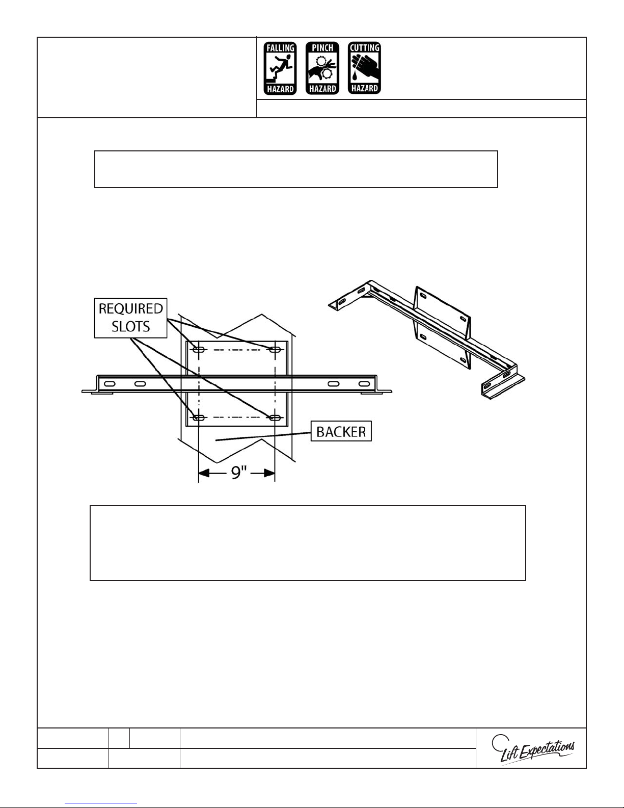
Note: If conversion rail brackets are provided follow instructions
below; if not provided proceed to the general rail bracket page
Conversion Bracket Mounting Points
These drawings depict sample construction only. It is the responsibility of the installer/
contractor or engineer to design and specify structural supports. All construction to be in
compliance with local codes.
Step 1 Reference rail wall reinforcement sheet in the
eld drawing packet.
Step
2 If the conversion rail brackets are provided, then reference
the illustration for the required (4) slots as fastening points
into the backer.
PTM30167-B
27 FEB 2018
WARNING:
1726 North Ballard Road, Suite 1 - Appleton, WI 54911 - 920.991.9082
Technical Support 855.804.5774 - [email protected]
W
E
Page 12
Conversion Rail Bracket
Page 12
Installation Instructions
(Optional)
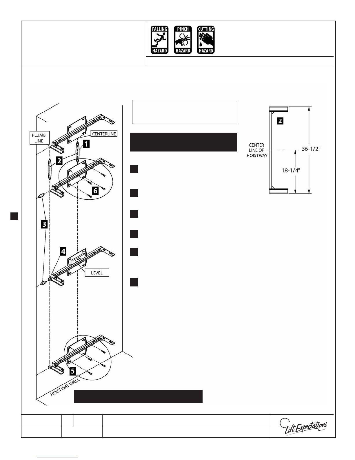
Note: The use of plumb line is recommended for verifying the hoistway dimensions and for locating and marking the center
line during rail bracket installation.
Series: 114, 021
Note: If conversion rail brackets are
provided follow instructions below; if
not provided proceed to next page.
ASSEMBLE MAIN RAIL PER FIELD
DRAWINGS
Use eld drawings to determine where to
1.
center the rail on the hoistway wall, and
plumb center line.
Measure over from the center line 18-1/4”
2.
and plumb a line to the left or right.
Refer to eld drawings to determine
1.
3.
location of each bracket and mark heights.
Level bracket, align side of bracket to plumb
4.
line, and mark (4) holes.
Drill (4) appropriately sized pilot holes per
5.
rail bracket. Fasten brackets into place with
appropriate hardware. Ensure rail brackets
are level. Shim as required.
Continue to fasten remaining rail brackets
6.
(except the jack and pedestal brackets)
onto wall. The jack and pedestal brackets
will be installed during rail installation.
Locate the positions for both the jack and
pedestal brackets, clamp each bracket onto
the bracket below their designated
mounting height.
DO NOT FASTEN PEDESTAL OR JACK
BRACKETS TO THE WALL.
VERIFY ALL FASTENERS ARE SECURE
PTM30168-C
29 MAR 2018
1726 North Ballard Road, Suite 1 - Appleton, WI 54911 - 920.991.9082
Technical Support 855.804.5774 - [email protected]
W
E
Page 13
Rail Bracket Installation
Page 13
Series: 114
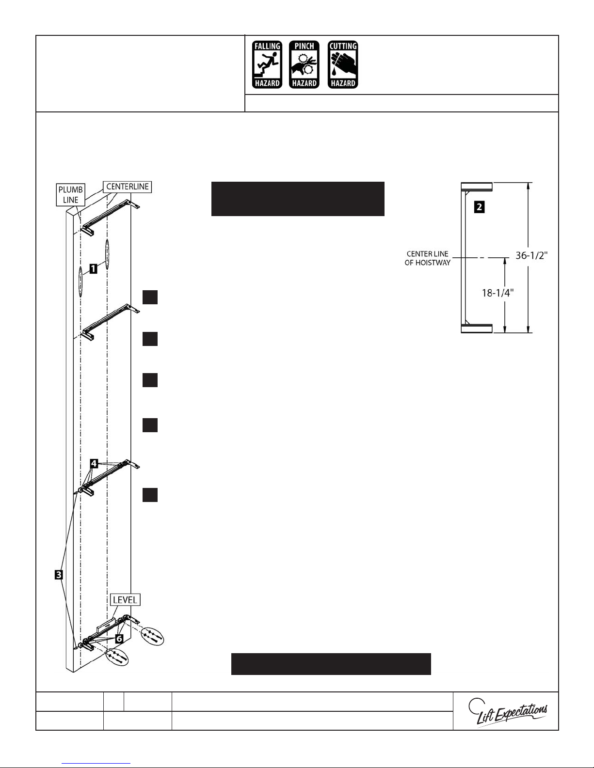
Note: The use of a plumb line is recommended for verifying the hoistway dimensions and for
locating and marking.
ASSEMBLE MAIN RAIL PER
FIELD DRAWINGS
Use eld drawings to determine where to center the rail
1.
on the hoistway wall and plumb a centerline.
Measure over form the centerline 18-1/4” and plumb
2.
line to the left or right of the centerline.
Refer to eld drawings to determine location of each
3.
bracket and mark heights.
Place level on bracket, align side of bracket to plumb line, and mark (4)
4.
holes.
Drill (4) appropriately sized pilot holes.
5.
Realign bracket before fastening to wall with appropriate hardware, shim
6.
as required.
Continue fastening all rail brackets onto the wall until complete, except for
7.
the jack & pedestal brackets which will be installed during rail installation.
Locate positions for both the jack and pedestal brackets and clamp each
bracket onto the bracket below their designated mounting height.
DO NOT ATTACH PEDESTAL OR JACK BRACKETS TO THE WALL.
PTM30169-C
16 MAR 2018
VERIFY ALL FASTENERS ARE SECURE
1726 North Ballard Road, Suite 1 - Appleton, WI 54911 - 920.991.9082
Technical Support 855.804.5774 - [email protected]
W
E
Page 14
RAIL AND PEDESTAL
Page 14
INSTALLATION
Remove protective
coating from rail
with non-residual
solvent.
TOP VIEW OF RAIL & PEDESTAL BASE
C
L
2, 3, 4
2
CLIP
4
4 1/2”
CRUSH
CRUSH
HAZARD
HAZARD
CRUSH
CRUSH
HAZARD
HAZARD
CUTTING
HAZARD
HAZARD
CRUSH
FALLING
HAZARD
PINCH
CRUSH
HAZARD
HAZARD
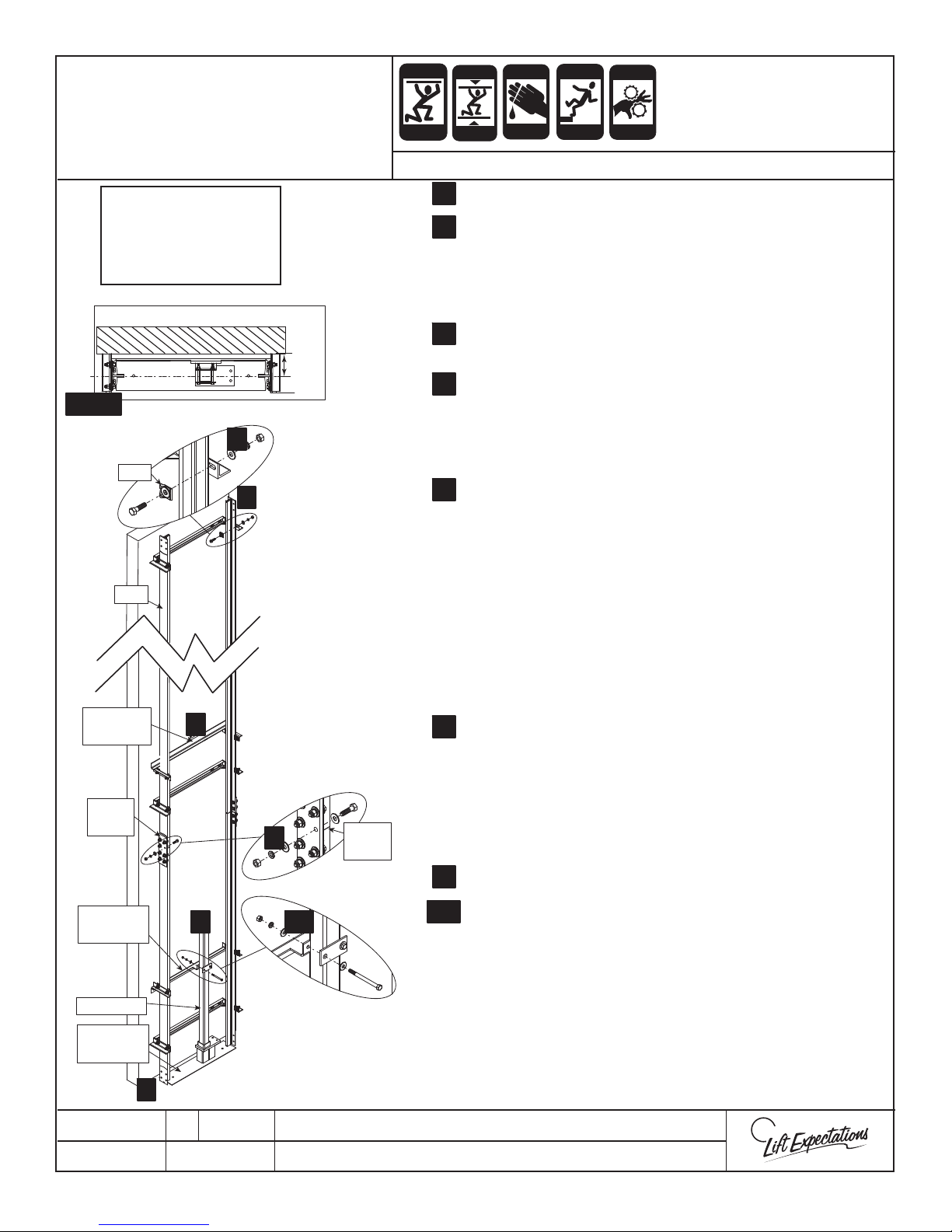
SERIES : 114
1. Set left rail into position with the tongue end facing up.
1.
2. Use a 6’ level to ensure left rail is plumb and 4 1/2” from
2.
the center of the rail wall. Fasten left rail to each rail bracket with the following hardware:
(2) - rail clips (2) - 1/2” lock washers
(2) - 1/2” -13 x 1-1/2” bolts (2) - 1/2” -13 nuts
(2) - 1/2” at washers
3. Place pedestal base into position and set right rail into
3.
position with the groove end facing up.
4. Use a 6’ level to ensure right rail is plumb 4 1/2” from the
4.
center of the rail wall Fasten right rail to each rail bracket
with the following hardware:
(2) - rail clips (2) - 1/2” lock washers
(2) - 1/2” -13 x 1-1/2” bolts (2) - 1/2” -13 nuts
(2) - 1/2” at washers
5. Hand tighten both sh plates to lower rails with:
5.
(8) - 1/2” -13 x 1-3/4” bolts (8) - 1/2” lock washers
(16) - 1/2” at washers (8) - 1/2” -13 nuts
RAIL
JACK
BRACKET
FISH
PLATE
PEDESTAL
BRACKET
PEDESTAL
PEDESTAL
BASE
8
5
9 10
RAIL
JOINT
6. Set upper rails into place one at a time and hand tighten
sh plates to both upper rails with the following hardware:
(8) - 1/2” -13 x 1-1/2” bolts (8) - 1/2” lock washers
(16) - 1/2” at washers (8) - 1/2” -13 nuts
Check for plumb with lower sections and securely fasten all
sh plate and rail bracket hardware to rail.
7. Continue installing additional rail sections until complete.
Verify rail is plumb and securely fastened.
8. Fasten the jack and pedestal brackets onto both sides of
8.
the rail at the predetermined locations with provided
hardware. (refer to eld drawings)
(4) - rail clips (4) - 1/2” lock washers
(4) - 1/2” -13 x 1-1/2” bolts (4) - 1/2” -13 nuts
(4) - 1/2” at washers
Note: Number of jack pedestal brackets may vary
depending on job. (Refer to eld drawings)
Set pedestal into pedestal base.
9.
Hand tighten pedestal to pedestal bracket (if provided)
10.
with:
(2) - 3/8”-16 x 4-1/2” bolts (4) - 3/8” at washers
(2) - 3/8” lock washers (1) - clamping plate
(2) - 3/8”-16 nuts
11.
Plumb pedestal with a level and securely tighten.
12.
Check rail splices and le/grind where necessary to ensure
a smooth and quiet ride.
1
PTM30172-C
23 FEB 2018
1726 North Ballard Road, Suite 1 - Appleton, WI 54911 - 920.991.9082
Technical Support 855.804.5774 - [email protected]
W
E
Page 15
CRUSH
Page 15
CUTTING
ECO-SYSTEM
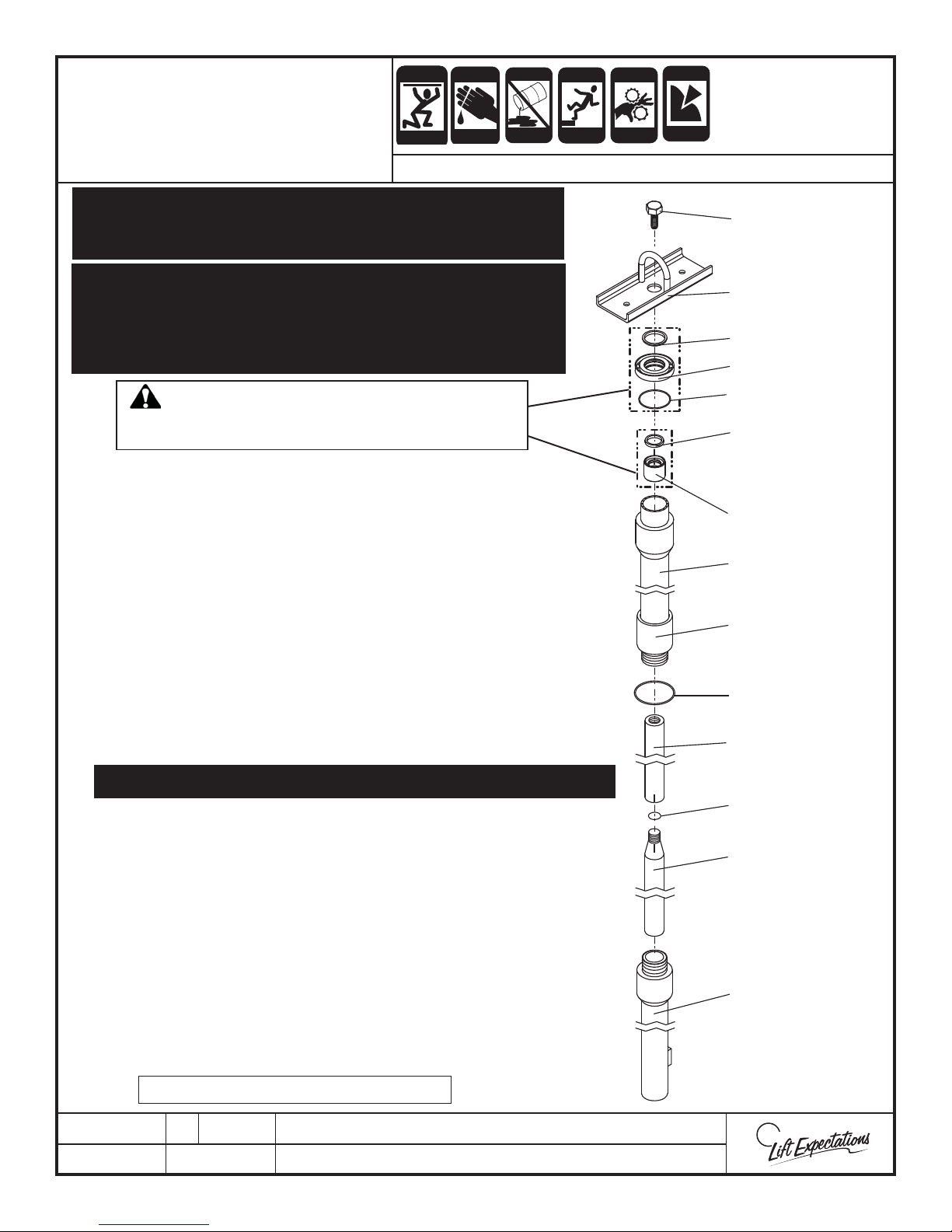
TWO PIECE
CRUSH
HAZARD
JACK ASSEMBLY
HAZARD
SERIES 114 - 116
ATTENTION
Make sure that all pistons, cylinder and components are kept from
damage, loss or contamination.
CRUSH
HAZARD
HAZARD
HAZARD
FALLING
HAZARD
PINCH
CRUSH
HAZARD
HAZARD
PUNCTURE
HAZARD
BOLT
Carefully examine piston for damages, scratches, score marks or nicks.
The damage must be removed prior to changing or assembling seals,
using a 12” smooth at le, 180 and 240 grit emery cloth. Bad damage
can be removed using le on a 45° angle to the center line of piston,
nish the surface with 240 grit emery cloth.
WARNING
DO NOT DISASSEMBLE THESE TWO ASSEMBLIES.
IF SEAL IS BROKEN, THE PARTS WILL NEED TO BE REPLACED.
Step 1 Disassemble jack parts (leave bottom piston in bottom
sleeve) and bring into hoistway. Use a spanner wrench (142mm,
pin diameter 8mm) for this step. Use bell hoist for chain
hoisting parts into place. Clean all threads with a non-residual
solvent. Wood “V” blocks may help for maintaining jack position
while assembling.
2 Set bottom assembly onto jack cup (refer to jack installation).
Step
3 Place O-ring between pistons. Do not crossthread! Thread top
Step
piston & bottom piston together with provided thread locker until
painted lines match.
4 Plumb and polish joint. Check for clear and smooth surface
Step
between pistons.
BELL HOIST
WIPER SEAL
FLANGE
O - RING
MAIN SEAL
(TEXTURED
SIDE UP)
GLAND
TOP SLEEVE
COLLAR
O - RING
5 Fit O-ring onto bottom of top sleeve.
Step
While threading be careful not to damage and/or scar the inside of top sleeve.
Step
6 Using provided thread locker, thread top sleeve into bottom
sleeve. Use a spanner wrench (142mm, pin diameter 8mm) for
this step. Refer to jack installation for PRV positioning. Remember,
DO NOT CROSSTHREAD!
7 Fasten top sleeve to jack bracket. If a second jack bracket is
Step
provided, fasten to bottom sleeve (reference eld drawings for
bracket locations.)
8 Insert gland assembly into top sleeve.
Step
9 Fasten ange assembly to top sleeve with socket head cap screws.
Step
Refer to jack installation for over ow relief positioning.
10 WAIT 24 HOURS BEFORE FILLING WITH OIL.
Step
Return to Jack Installation Instructions
PTM30061-C
1/21/2013
1726 North Ballard Road, Suite 1 - Appleton, WI 54911 - 920.991.9082
Technical Support 855.804.5774 - [email protected]
TOP PISTON
O - RING
BOTTOM PISTON
BOTTOM SLEEVE
W
E
Page 16
JACK INSTALLATION
Page 16
Note: Contaminated oil will cause valve problems and more intensive maintenance.
Series: 114
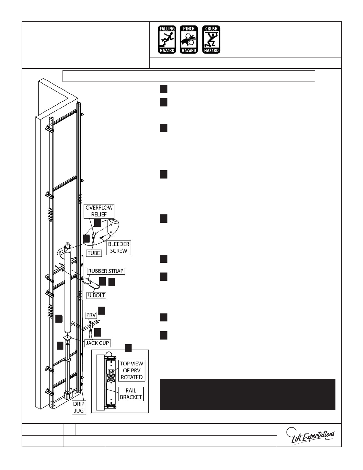
1. Set jack cup onto pedestal.
1.
2. Verify that socket head cap screw is installed in
2.
bottom of jack. Set jack onto jack cup by inserting head
of screw into jack cup alignment hole.
3. Loosely fasten jack to jack brackets with U-bolt, rubber
3.
strap and provided hardware. (Trim the rubber strap if
necessary)
Note: Do not double up the rubber strap and
be sure to have the gap in the front of the jack.
4. Remove the plate from jack inlet port and mount Pipe
4.
Rupture Valve (PRV) to jack with provided O-ring,
screws and washers.
Note: Lubricate O-ring with hydraulic oil. The O-ring
and mating surfaces must be clean.
5. Attach hydraulic pipe from PRV to tank.
8
5.
Note: The inside of the pipe and attaching threads
9
must be clean. All hydraulic piping must meet
ASME 17.1/CSA B44 and local codes.
6. Rotate PRV as needed to maintain mechanical
6.
clearances.
7.
3
7
7. Plumb and securely fasten jack to jack brackets by
tightening U-bolt.
Note: Compress rubber strap approx. 1/8” do not
over tighten.
4
8. Screw tube tting into weep hole on the jack crown
2
5
1
6
8.
over ow relief with elbow facing downward direction.
9.
9. Press tube over tube tting rmly until tube is fully
secure, run down jack, and into drip jug (do not
obstruct any part of the elevator) and secure tube to
jack.
Use a laser level to verify rail system, pedestal and jack are all
plumb and properly aligned. If the jack and rail system are not
properly installed this may cause premature seal failure, abrasive wearing, leaks and noise throughout the elevator system.
PTM30173-B
29 MAR 2018
1726 North Ballard Road, Suite 1 - Appleton, WI 54911 - 920.991.9082
Technical Support 855.804.5774 - [email protected]
W
E
Page 17
RAM HEADER
Page 17
INSTALLATION
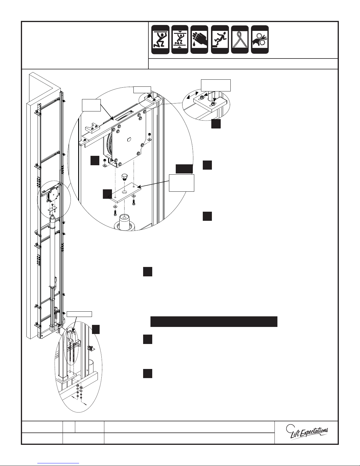
RAM’S
HEADER
GUIDES
CRUSH
CRUSH
HAZARD
HAZARD
CRUSH
CRUSH
HAZARD
HAZARD
SERIES : 114
CUTTING
CRUSH
HAZARD
HAZARD
ADJUSTMENT
FALLING
HAZARD
NUTS
5
KINK
CRUSH
HAZARD
HAZARD
PINCH
CRUSH
HAZARD
HAZARD
Shackles
5
1, 2
JACK
MOUNTING
PLATE
4
Remove jack mounting plate from ram
1.
header by removing the following:
(2) - 3/8” - 16 x 1-1/4” bolts
(4) - 3/8” at washers
(2) - 3/8” - 16 nylock nuts
Remove bolt from top of jack and fasten
2.
the jack mounting plate to the jack with
the previously removed bolt.
(M30 x 3.5 bolt)
Verify jack bolt is secure.
3.
Set ram header into place and fasten to the jack
4.
mounting plate with the previously removed hardware:
(2) - 3/8” - 16 x 1-1/4” bolts
(4) - 3/8” at washers
(2) - 3/8” - 16 nylock nuts
TORQUE 3/8” FASTENERS TO 25 FT-LBS.
6
Use adjustment nuts on the ram header to adjust rail
5.
guides left or right resulting in a snug t between the rails.
Verify fasteners are securely fastened.
PTM30174-C
09 MAR 2018
Remove hardware and place shackle rods into
6.
pedestal base. Then reinstall previously removed hardware
so shackle has max adjustment remaining.
1726 North Ballard Road, Suite 1 - Appleton, WI 54911 - 920.991.9082
Technical Support 855.804.5774 - [email protected]
W
E
Page 18
CONTROLLER
Page 18
CRUSH
CUTTING
ELECTRIC
FALLING
PINCH
STATIC
ELECTRICITY
INSTALLATION AND
WIRING
CRUSH
HAZARD
HAZARD
SERIES : 114, 116
CRUSH
HAZARD
HAZARD
HAZARD
HAZARD
CRUSH
HAZARD
HAZARD
HAZARD
Disconnect Power Before Wiring
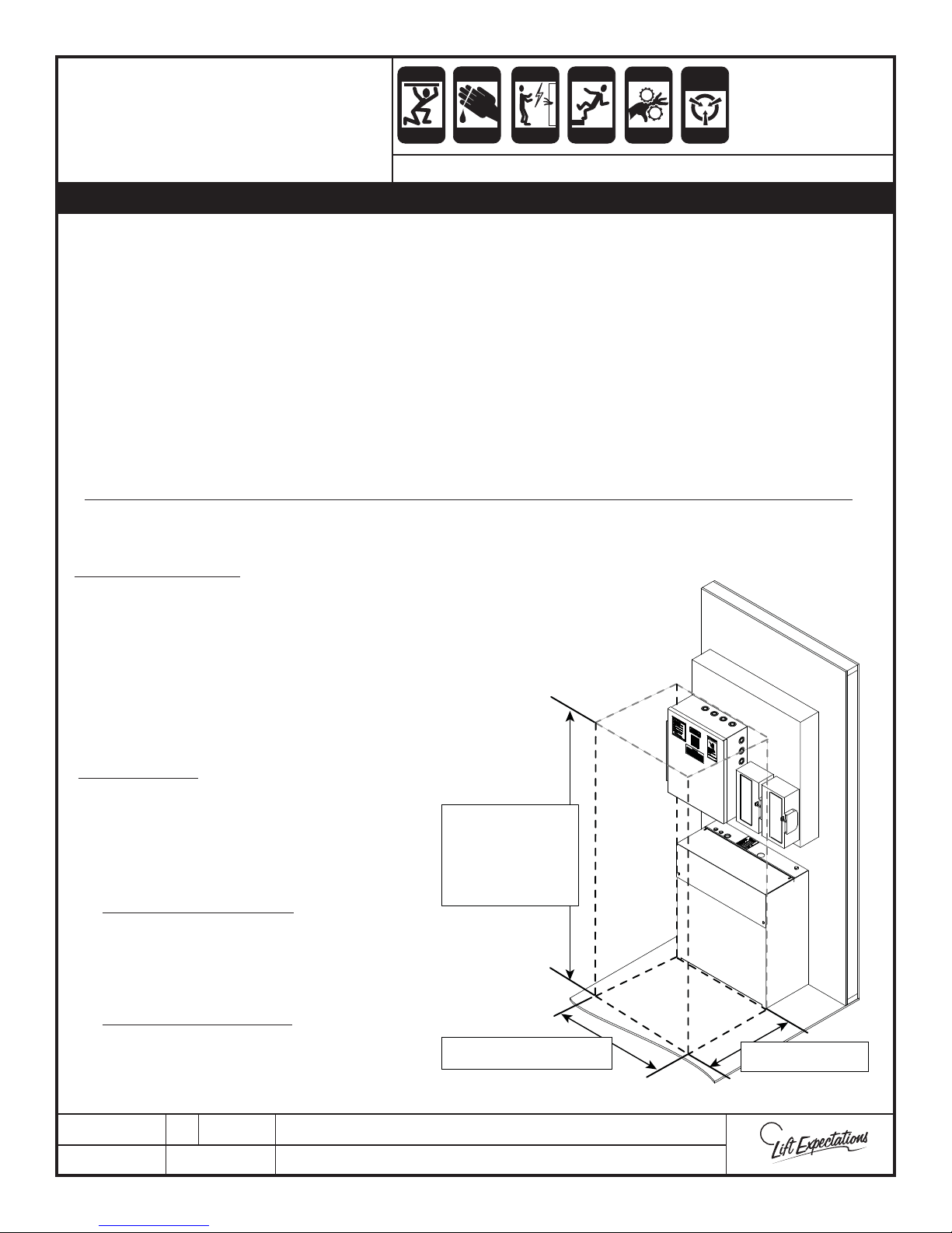
• Locate controller enclosure in the machine room as required by code.
• Wire gauge requirements:
10 gauge wire for power to motor
14 gauge for solenoid coils
18 for all low voltage
• Refer to unit speci c schematics in eld drawings to complete wiring.
Wire per N.E.C. and local codes.
Note: Not all controller terminals or travel cable wire may be used. High voltage and low
voltage wire must run separate and only cross over perpendicular to each other.
• Locate and check for correct fuse sizes.
Per NEC Code 110.26 .......
Clear Working Space. The working space
required by this section must be clear at all
times. Therefore, this space isn’t permitted
for storage. When normally enclosed live
parts are exposed for inspection or servicing,
the working space, if in a passageway or
general open space, must be suitably
guarded.
Working Space. Equipment that may need
examination, adjustment, servicing, or
maintenance while energized must have
working space provided in accordance
with(1), (2), and (3):
1. Depth of Working Space. The working
space, which is measured from the
enclosure front, must not be less than the
distance of 36”.
2. Width of Working Space. The width of the
working space must be a minimum of 30”,
but in no case less than the width of the
equipment.
The height of working
space in front of
equipment must be a
minimum of 6-1/2 ft. or
height of the equipment,
whichever is greater per
NEC Code
30” minimum width or
the width of the equipment
2
3
1
0
1
V
0
V
36” from the face of
the equipment
PTE10056-I
09 MAR 2018
1726 North Ballard Road, Suite 1 - Appleton, WI 54911 - 920.991.9082
Technical Support 855.804.5774 - [email protected]
W
E
Page 19
CONTROLLER
Page 19
CRUSH
CUTTING
ELECTRIC
FALLING
PINCH
STATIC
ELECTRICITY
INSTALLATION AND
WIRING
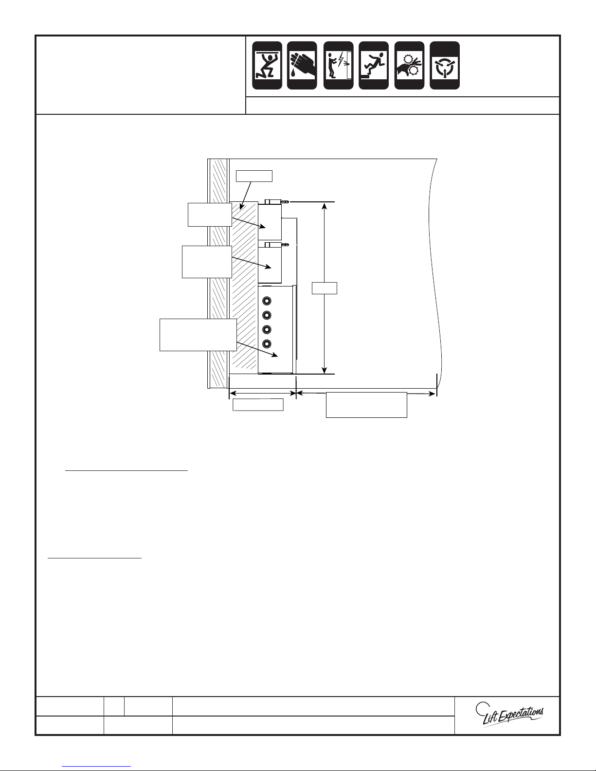
Note: The machine room may be placed on any oor of on any
Disconnect
110V
Disconnect/
Light Switch
230V
Controller Size
Standard
24-1/2” x 18-5/8”x 8”
CRUSH
HAZARD
HAZARD
SERIES : 114, 116
Overhead View
level of the home
Build out
CRUSH
HAZARD
HAZARD
30 in
HAZARD
HAZARD
CRUSH
HAZARD
HAZARD
HAZARD
14-1/2 in
the equipment
Per NEC Code 110.26 Continued .......
3. Height of Working Space (Headroom). The height of the working space in front of equipment must
not be less than 6½’ measured from the grade, oor, platform, or the equipment height, whichever is
greater.
Other equipment must not extend more than 6” into the controller working space.
Additional Notes
• A lockable service disconnect must be placed within sight of the controller and must be easily
accessible in case of an emergency.
• Machine room must contain a convenience outlet and light with switch.
• The temperatures must be maintained between 60°- 110°F and must not be exposed to the
elements (with a relative humidity not to exceed 95%).
36 in of the face of
PTE10056-I
09 MAR 2018
1726 North Ballard Road, Suite 1 - Appleton, WI 54911 - 920.991.9082
Technical Support 855.804.5774 - [email protected]
W
E
Page 20
Page 20
ANTI-
GMV/OLS
HYDRAULIC POWER UNIT
INSTALLATION
STATIC
ALERT
CRUSH
CRUSH
HAZARD
HAZARD
SERIES : 114 , 116
CRUSH
CRUSH
HAZARD
HAZARD
CUTTING
CRUSH
HAZARD
HAZARD
ECO-SYSTEM
HAZARD
ELECTRIC
HAZARD
FALLING
HAZARD
INHALATION
HAZARD
PINCH
CRUSH
HAZARD
HAZARD
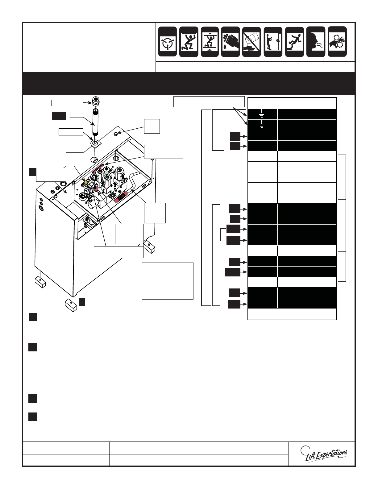
Do not allow the hydraulic oil to become contaminated with foreign debris by maintaining
a clean work environment. Always keep the tank cover sealed and secured and do not lift the tank
when its lled with hydraulic uid.
To Controller Ground Lug
10 GA14 GA
T1
T2
Valve Terminals
Ground
Ground
T1 Motor
T2 Motor
T3 Motor
14 SM110 Power
13 SM110 Power
PUMP
6
TERMINALS
PIPE FITTING
PIPE
3, 5
GASKET
HAND
PUMP
DIP
STICK
OIL SHUT OFF
VALVE HANDLE
12 Thermal Cut - Out
WHITE PUMP TERMINALS WEC DOES NOT USE
11 Thermal Cut - Out
HAND
PUMP
HANDLE
MANUAL
LOWERING
BUTTON
(LOW PRESSURE SWITCH)
LPS
WEC USES THE BLACK CONTROL TERMINALS
Note:
Do not jumper
terminals 2-5 at the
hydraulic tank
terminals
1
1. Insert the (4) rubber feet into bottom of power unit.
1.
2. Remove temporary plugs, by unscrewing the plug located in the ball valve in the back of the tank. Also
remove the plug on top of the tank were the pipe goes through.
3. Securely install the gasket, pipe and pipe tting into the valve assembly.
3.
4. Route the hydraulic hose if supplied, between the piping from the jack to pipe connection on the top of the
power unit. Fill in the blanks on the exible hose tag. (route hose per ASME A17.1/CSA B44 and local code)
18 GA
HSV
VC
SV
LPS
LPS
VC
VC
DV
10 COM
9 VMP/S
8 LPS
7 LPS
6
5 VML4 VML+
3
2 VMD1 VMD+
Controller Connection
Note: The hydraulic hose will shrink when pressurized. Be sure there’s slack between the piping and the
hydraulic power unit to accommodate this.
5. Attach the hydraulic hose to the pump tting with hydraulic thread compound on threads.
5.
(attach hose per ASME A17.1/CSA B44 and local code)
6. Wire power unit to the controller using electrical schematic.
6.
(hydraulic power unit and wiring must meet N.E.C. and local code)
7.
Note: The terminal mounting plate can be removed for ease of wiring.
PTM30065-H
7 MARCH 2018
1726 North Ballard Road, Suite 1 - Appleton, WI 54911 - 920.991.9082
Technical Support 855.804.5774 - [email protected]
W
E
Page 21
FINAL LIMIT
Page 21
ANTI-
STATIC
CRUSH
CUTTING
CRUSH
ELECTRIC
FALLING
PINCH
INSTALLATION
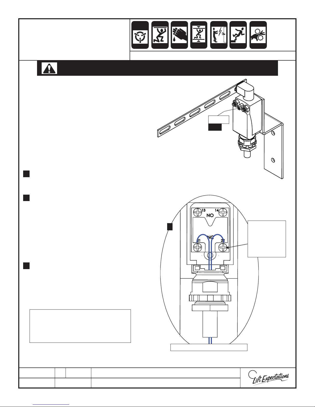
DO NOT RUN ELEVATOR WITHOUT THE FINAL LIMIT SWITCH INSTALLED!
1.
Position the top nal limit switch
assembly in the desired location at the
top of the elevator hoistway. Only the
switch arm from the assembly must
make contact with the elevator and shall
fully actuate before the elevator hits any
obstruction. (i.e., ceiling, electrical and/
or mechanical part, etc.)
2.
Fasten the nal limit switch assembly
to the hoistway with the appropriate
hardware.
Loosen the screw and open cover. Verify
3.
the normally closed contacts with a
multi-meter.
ALERT
SERIES : 114, 116
HAZARD
HAZARD
HAZARD
HAZARD
Screw
3, 6
HAZARD
HAZARD
4.
Wire to the previously veri ed normally
closed terminals. All wiring must meet
N.E.C. and local codes.
Note: Do not over tighten
terminals. Terminals should be
torqued to 7lb-in max.
5.
Verify the operation of the nal limit
switch.
6.
Replace cover and refasten screw.
Adjust as necessary, the nal limit switch
7.
assembly may move or need adjustment
after the elevator car is installed.
Note: Verify the switch actuates and
disconnects power to the driving
machine before the elevator is at its
max extent or strikes any obstruction.
4
Torque the
Normally
Closed
Terminals
to 7lb-in max.
PTM30125-E
7 FEB 2018
Wire to Terminals TF1and TF2
1726 North Ballard Road, Suite 1 - Appleton, WI 54911 - 920.991.9082
Technical Support 855.804.5774 - [email protected]
W
E
Page 22
ANTI-
SEPARATELY
Page 22
STATIC
CRUSH
CUTTING
ELECTRIC
FALLING
PINCH
PENDANT CONTROL
SERIES : 114 - 116
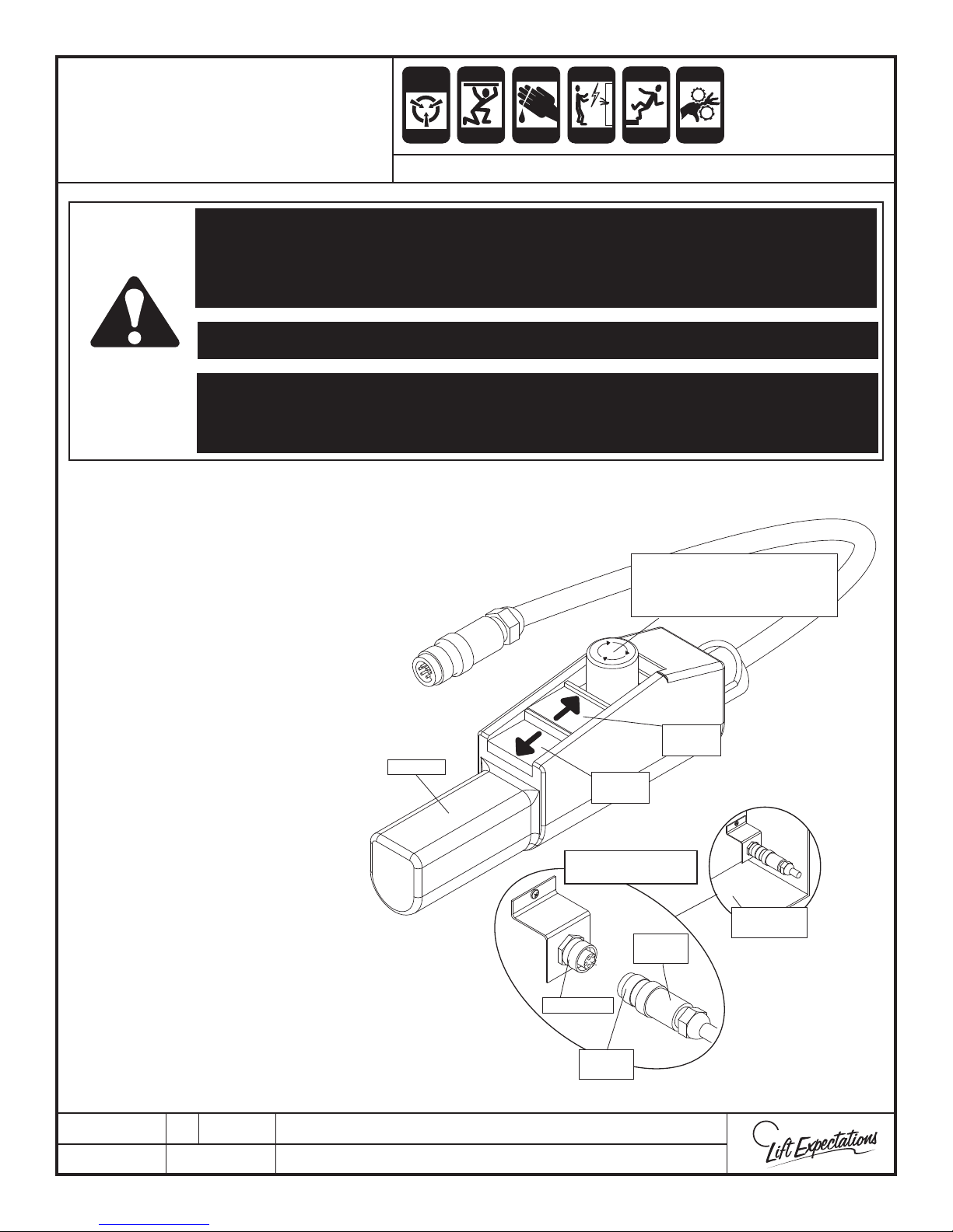
VERIFY TOP FINAL AND BOTTOM FINALS ARE INSTALLED AND WORKING BEFORE USING
PENDANT! HYDRAULIC PUMP UNIT SHOULD BE INSTALLED AND WIRED BEFORE USING
PENDANT!
VERIFY THE HOISTWAY IS CLEAR OF ALL PERSON(S) WHENEVER USING PENDANT!
THE PENDANT CONTROL IS A TEMPORARY MEANS OF OPERATING THE UNIT BY A
TRAINED AUTHORIZED ELEVATOR CONTRACTOR. THE PENDANT CONTROL MUST ONLY
BE USED FOR SERVICING, INSTALLATION OR MAINTENANCE WORK!
TO USE:
Step 1 Verify top and bottom nals and pit switch
are installed.
Step 2 Plug in UPS (battery).
ALERT
CRUSH
HAZARD
HAZARD
CRUSH
HAZARD
HAZARD
WARNING
HAZARD
CRUSH
HAZARD
HAZARD
HAZARD
EMERGENCY STOP BUTTON
- PRESS TO ENGAGE
- TURN CLOCKWISE TO RELEASE
Step 3 Insert pendant plug into receptacle.
Step 4 Rotate pendant nut clockwise to fasten
onto receptacle.
Step 5 Turn UPS “ON”
Step 6 Turn PLC toggle switch to the “ON”
TO DISCONNECT:
Step 1 Turn “OFF” all power to the unit at the
Step 2 Turn PLC toggle switch to the “OFF” position.
Step 3 Unplug UPS (battery).
Step 4 Rotate pendant nut counterclockwise and remove
from receptacle.
position.
controller, disconnect and battery.
PENDANT
LOWERS
ELEVATOR
INSERT PENDANT PLUG
INTO RECEPTACLE.
PENDANT
RECEPTACLE
PENDANT
NUT
RAISES
ELEVATOR
CONTROLLER
BOX
PLUG
PTE10142-C
24 APR 2015
1726 North Ballard Road, Suite 1 - Appleton, WI 54911 - 920.991.9082
Technical Support 855.804.5774 - [email protected]
W
E
Page 23
CRUSH
Page 23
CRUSH
CUTTING
ECO-SYSTEM
ELECTRIC
FALLING
PINCH
PISTON PROJECTION
CRUSH
HAZARD
HAZARD
CRUSH
HAZARD
HAZARD
CRUSH
HAZARD
HAZARD
HAZARD
HAZARD
HAZARD
CRUSH
HAZARD
HAZARD
SERIES : 114 , 116
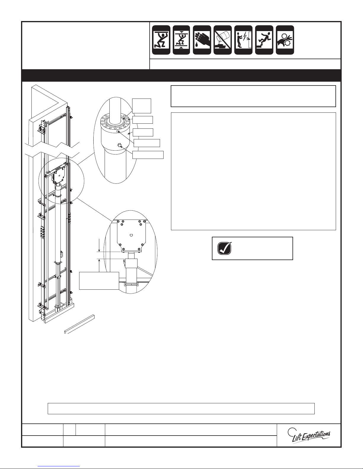
Bleed the jack every morning before running during the elevator installation process.
Use AW-32 hydraulic oil and maintain oil temperature
Wiper
Blade
Crown
Jack
Drain Hole
Bleeder Bolt
INFORMATION ON PISTON PROJECTION
By de nition, Piston Projection is the linear distance
that the rod has traveled from its fully retracted out
position.
When fully retracted, the rod will protrude from the
cylinder. This distance is NOT included in the piston
projection dimensions given for the elevator.
With the jack bottomed out, measure the distance
from the top face of the crown to the bottom plate of
the ram header (as shown). Take note of this distance.
When setting piston projection, add the initial rod
extension to the piston projection dimensions given
in eld drawings, then measure in the same fashion.
between 60°F and 110°F
KEEP AREA
AND OIL CLEAN
INITIAL EXTENSION
OF BOTTOMED
OUT JACK
3. Bleed the air from the jack by running pump. (Refer to pendant control page)
4. Once uid begins to seep out of bleeder stop the pump. Securely fasten the bleeder bolt in the
jack sleeve. Once complete, clean up the seepage.
5. Using the pendant control, project piston to proper distance and continue with shackle
installation. (Refer to eld drawings)
Note: Additional weight may be required during installation to assist unit in descending.
1. Fill pump with hydraulic oil until motor is
submerged completely and add oil as necessary.
Note: Typically 25-30 gallons total.
2. Loosen, but do not remove, the bleeder bolt.
Note : Frequently clean exposed jack cylinder,
wiper ring, and crown with a clean rag
throughout installation.
PTM30177-G
6 MAR 2018
1726 North Ballard Road, Suite 1 - Appleton, WI 54911 - 920.991.9082
Technical Support 855.804.5774 - [email protected]
W
E
Page 24
CRUSH
Page 24
CRUSH
CUTTING
FALLING
PINCH
SLING INSTALLATION
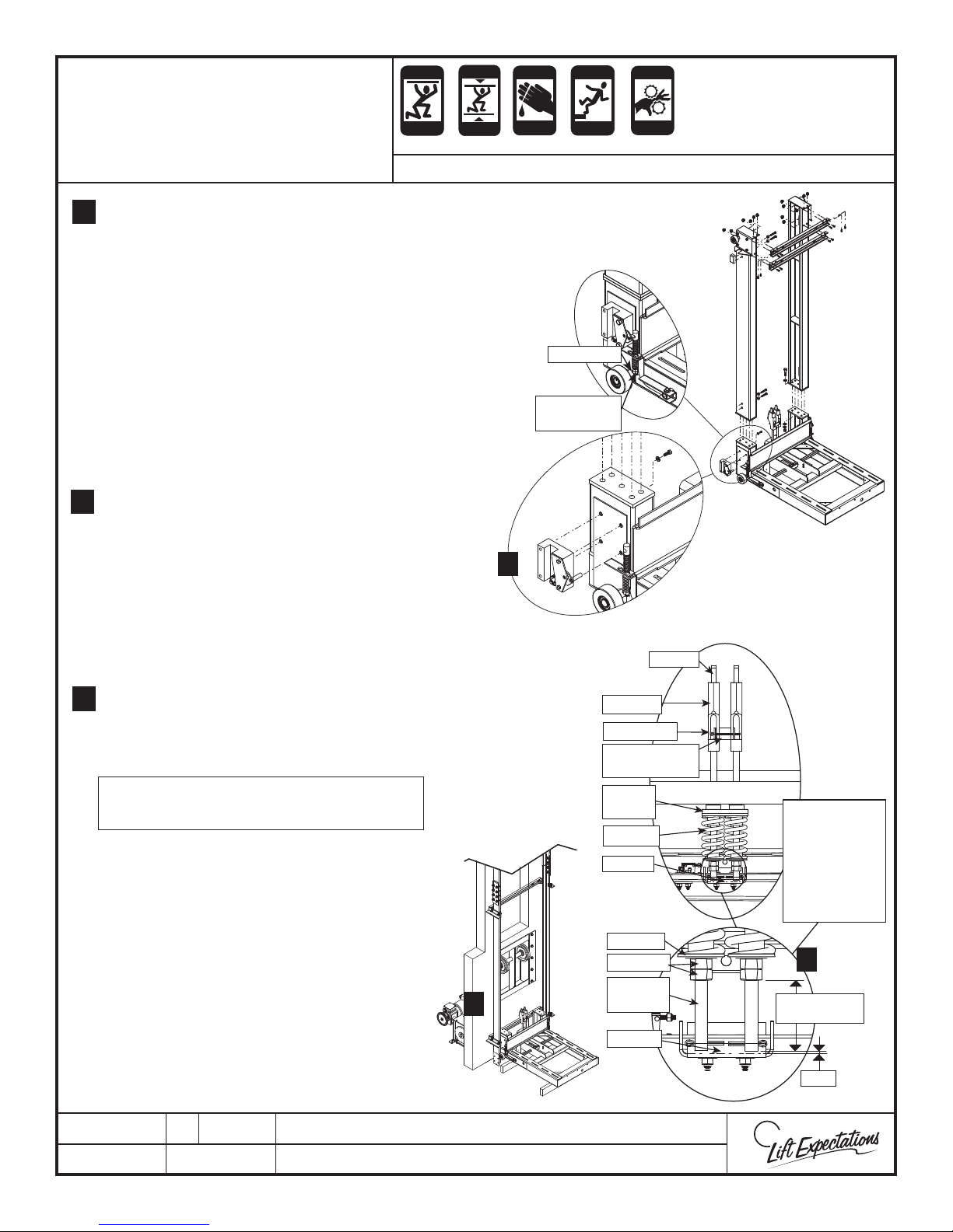
Remove the left safety block from the sling
1.
base by removing the following (Grade 8)
hardware.
(4) - 3/8”-16 x 1” bolts
(4) - 3/8” lock washers
Remove the bolts from the safety actuation
2.
links on both side of the slings and swing
clear of the square rod.
Note: Safety actuation paddle will
rotate freely.
Assemble shackles in sling with provided
3.
hardware: rubber pad, springs, plastic
bushings, washers, ¾” jam nuts, and cotter
pin. Place the shackle nuts initially at 3 ½”
from the bottom of the shackle rod.
CRUSH
HAZARD
HAZARD
CRUSH
HAZARD
HAZARD
SERIES : 114, 021, 022
1
CRUSH
HAZARD
HAZARD
COTTER PIN
ADJUSTMENT
NUTS
HAZARD
CRUSH
HAZARD
HAZARD
Loosen the eccentric rollers and adjust to
4.
maximize rail clearance.
5.
Bring the sling into the hoistway and block
up as required. A minium of 4” is required for
safety paddle.
Note: The top of the sling base should
be 2” below the lowest oor landing.
Move the sling into position. Align the right
6.
safety block with right stick of the t-rail. Then
pivot the left side of the sling into position
and center between rails.
Reattach left safety block to the sling with
7.
previously removed hardware.
(4) - 3/8”-16 x 1” bolts
(4) - 3/8” lock washers
WEDGE
SHACKLE
COTTER PIN
ANTI-ROTATION
CLIP
RUBBER
STOP
SPRING
PADDLE
WASHER
JAM NUTS
SHACKLE
5
BOLT
PADDLE
PRE-SET
ADJUSTMENTS
ONLY!
DEPENDING ON
INSTALLATION
ADJUSTMENTS
MAY VARY!
3
RANGE
3-1/2" - 4-1/2"
1/16"
PTM30157-D
06 MAR 2018
1726 North Ballard Road, Suite 1 - Appleton, WI 54911 - 920.991.9082
Technical Support 855.804.5774 - [email protected]
W
E
Page 25
CRUSH
Page 25
CRUSH
CUTTING
FALLING
PINCH
SLING INSTALLATION
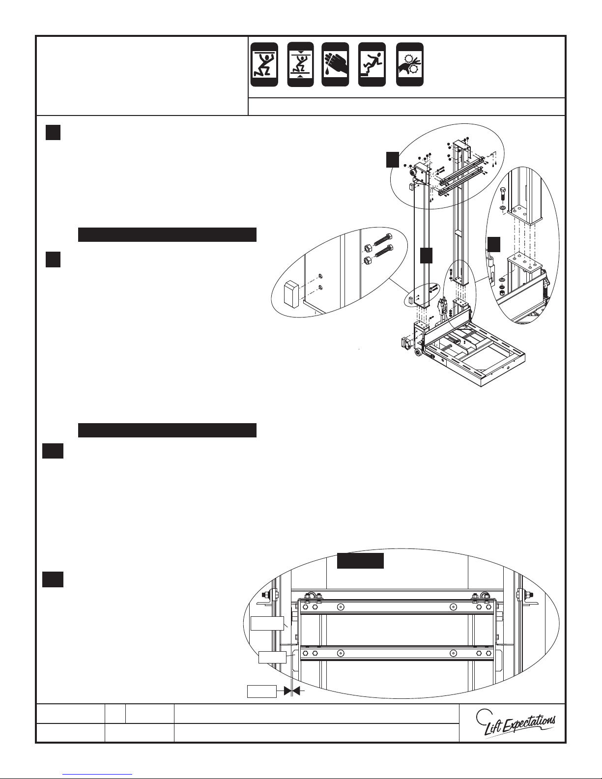
Mount left and right sling uprights onto
8.
sling base and hand tighten with the
following hardware:
(10) - 1/2”-13 x 1-1/2” bolts
(20) - 1/2” at washers
(10) - 1/2” lock washers
(10) - 1/2”-13 nuts
IMPORTANT: TORQUE TO 125 FT.-LBS.
Place top cross members into position
9.
with the sling uprights and hand tighten
with the following hardware:
FACE OF THE CROSS MEMBER
(8) - 3/8” -16 x 3/4” bolts
(8) - 3/8” -16 serrated ange
nuts
CRUSH
HAZARD
HAZARD
SERIES : 114, 021, 022
CRUSH
HAZARD
HAZARD
CRUSH
HAZARD
HAZARD
HAZARD
9
CRUSH
HAZARD
HAZARD
5
8
8
TOP OF UPRIGHTS
(4) - 3/8” - 16 x 1” bolts
(4) - 3/8” -16 serrated ange nuts
IMPORTANT: TORQUE TO 47 FT.-LBS.
Place (4) gibbs into position on the sling uprights and hand tighten into position with the
10.
following hardware:
(8) - 3/8” -16 x 2” bolts
(8) - 3/8” - 16 jam nuts
11.
Verify sling is square and plumb
and securely fasten all sling
hardware.
9, 10, 12
12.
Adjust (4) gibbs to center the
sling in the rail leaving no more
than a 1/16” gap between gibbs
and rail. Verify all (8) - gibb nuts
T RAIL
are jam locked against the sling
uprights. Verify sling is centered
in rail.
GIBB
PTM30157-D
06 MAR 2018
1/16"
1726 North Ballard Road, Suite 1 - Appleton, WI 54911 - 920.991.9082
Technical Support 855.804.5774 - [email protected]
W
E
Page 26
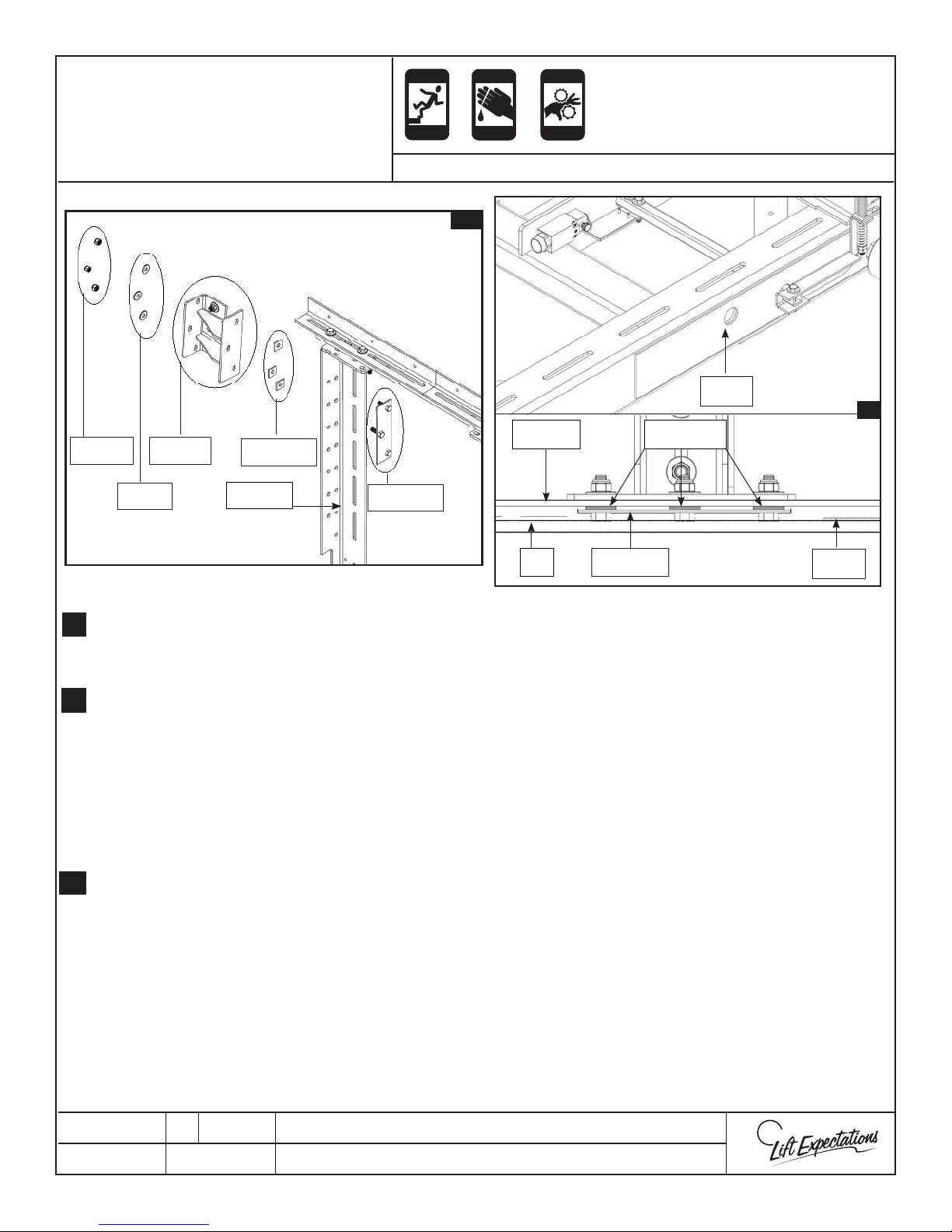
1.
3.
3/8” NYLON
Page 26
NUT
SLING EXTENSION
INSTALLATION
SIDE ARM
ASSEMBLY
3/8” SQUARE
WASHERS
FALLING
HAZARD
CUTTING
CRUSH
HAZARD
HAZARD
Series: 114, 021, 022
1, 3
EXTENSION
PINCH
HAZARD
HAZARD
SLING
CRUSH
DOUBLER
PLATE
2
3/8” SQUARE
WASHERS
3/8” FLAT
WASHER
Remove provided hardware. Insert the bolt plate through the desired holes on the
1.
EXTENSION
ARM
BOLT PLATE
ASSEMBLY
SLING
BASE
BOLT PLATE
ASSEMBLY
sling extension arm.
2.
Place the 3/8” square washers in the required locations.
NOTE: In the image above there’s an uneven surface (called the doubler plate) on the
main arms of the base sling. To verify the bolt plates bolts are touching the sling
extension, if not the (3) 3/8” square washers will be needed. If the bolts are touching
you do not need the (3) 3/8” square washers.
3.
Place the side arm on the bolts. Replace the previously removed hardware.
DOUBLER
PLATE
PTM30158-C
AUG 15, 2016
Technical Support 855.804.5774 - [email protected]/jsite/
1726 North Ballard Road, Suite 1- Appleton, WI 54911 - 920.991.9082
W
E
Page 27

4, 5, 7
Sling Extension
4.
4, 5
7, 8
Page 27
Installation
4, 5, 7
FALLING
HAZARD
CUTTING
CRUSH
HAZARD
HAZARD
PINCH
CRUSH
HAZARD
HAZARD
Series: 114, 021, 022
If side extensions are provided, determine
4.
elevator car outside DA dimension
(reference eld drawings for dimension).
Subtract 4” from the outside DA dimension
and adjust the side extensions to extend
out to this distance. The elevator car will
hang over the extensions 2” on each side.
3/8”
SCREWS
5
STANDARD STABILIZER
4, 5
O.D.
DIMENSIONS EXAMPLE
5
MINIMUM STABILIZER
TURNED STABILIZER
O.D.
Example
Only
Note: The maximum the elevator car can
hang o any edge of the sling extension is
3-3/16”. Reference the side extension
con gurations shown to best suit the
elevator car.
The sling extension can only extend to
the maximum length of 13”.
If your measurements requires a change
5.
other than the provided standard side arm.
You can change con guration to either
minimum, turned, maximum or some place
in between as depicted in the images. By
loosening and/or removing the
hardware, adjusting/sliding the side arm,
and then re-tightening.
6.
Adjust front extension angle by
loosening / removing provided hardware.
Place the front extension angle in the
desired position. Replace and re-tighten
the provided hardware. Following the rules
from step 4.
7.
Test t the sling extension on the sling
base. Determine if the elevator car pads are
needed. Make adjustments on the sling
extension as needed. If dimensions are not
correct repeat steps 1-6.
3/8”
FLAT
WASHER
3/8”
NYLON
NUT
3/8”
SCREWS
3/8”
FLAT
WASHER
FRONT
EXTENSION
ANGLE
3/8”
FLAT
WASHER
3/8”
NYLON
NUT
7, 8
6
MAXIMUM STABILIZER
PTM30158-C
AUG 15, 2016
Technical Support 855.804.5774 - [email protected]/jsite/
Secure the elevator car pads if they are
8.
needed. With the provided hardware attach
the sling to the sling base.
1726 North Ballard Road, Suite 1- Appleton, WI 54911 - 920.991.9082
W
E
Page 28
CRUSH
Page 28
CRUSH
CUTTING
FALLING
KINK
PINCH
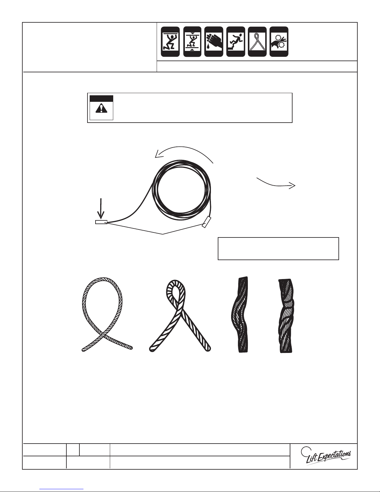
PROPER HANDLING OF
WIRE ROPE
USE PROPER CARE WHEN HANDLING WIRE ROPES!
DANGER!
FAILURE TO HEED MAY
RESULT IN DAMAGE OR INJURY
GENTLY HOLD
DOWN ONE END
A kink (or any other damage) in the rope is permanent,
CRUSH
HAZARD
HAZARD
CRUSH
HAZARD
HAZARD
CRUSH
HAZARD
HAZARD
HAZARD
Series: ALL
WIRE ROPE REPLACEMENT
a kinked rope must be replaced!
CAREFULLY UNCOIL ROPE
WHILE WALKING
DO NOT
TWIST OR KINK
THE ROPE!
CRUSH
HAZARD
HAZARD
CRUSH
HAZARD
HAZARD
SWEDGE
If swedge is not provided with
your unit use the wire rope ends.
STA RTING
TO LOOP
KINKED BY
TENSION
OPEN
KINK
CLOSED
KINK
CUTTING THE ROPE
Determine where the wire rope needs to be cut. Properly seize wire rope on both sides of where the
cut is to be made. Cut perpendicular to the wire rope between seized sections.
PTM20044-D
29 MAR 2018
1726 North Ballard Road, Suite 1 - Appleton, WI 54911 - 920.991.9082
Technical Support 855.804.5774 - [email protected]
W
E
Page 29
CRUSH
Page 29
CRUSH
CUTTING
FALLING
KINK
PINCH
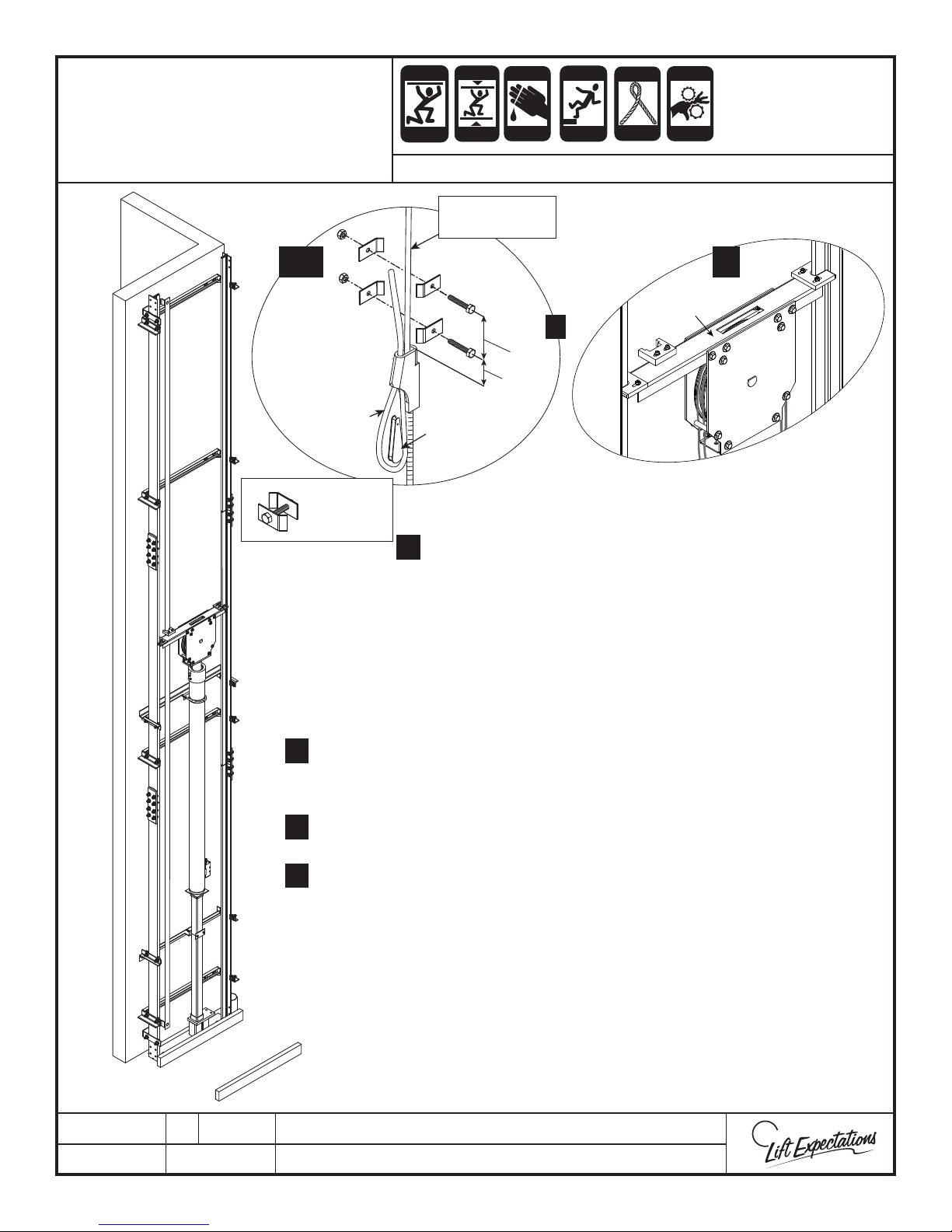
WIRE ROPE
INSTALLATION
3, 4
DEAD SIDE
(NON LOAD
BEARING)
CABLE
CLAMP
ASSEMBLY
CRUSH
HAZARD
HAZARD
CRUSH
HAZARD
HAZARD
CRUSH
HAZARD
HAZARD
HAZARD
CRUSH
HAZARD
HAZARD
CRUSH
HAZARD
HAZARD
SERIES : 114
LIVE SIDE
(LOAD BEARING)
1
RAM
HEADER
5
3"
1-1/2"
WEDGE
Route the wire ropes over the ram header sheave. Verifying
1.
the wire ropes are fully seated in each groove and under the
retainer pins. Verify even weight distribution of the wire ropes
on each side of ram header sheave.
Secure the wire ropes from any unintended movement as they may cause
2.
damage to the hoistway/components or injury to the installers.
Note: Verify wire ropes are not crossed at any point throughout their
complete length.
Route the wire rope closest to the rail wall through the shackle socket closest
3.
to the rail wall in the pedestal base. Create a loop by routing wire rope back
through the shackle socket. Insert wedge into the newly created loop.
Pull the wire rope and wedge tightly into the socket. Repeat this for other
4.
shackle.
5.
Fasten (4) cable clamps into the designated locations as described below:
The rst clamp shall be placed a maximum of 4 times the rope diameter
A)
above the shackle.
(Example: 3/8” wire rope= maximum distance of 1-1/2”)
The second clamp shall be located within 8 times the rope diameter
B)
above the rst clamp.
(Example: 3/8” wire rope = maximum distance of 3”)
Note: Verify the live side cable and dead side tail are close as possible
once the clamp is secure. Then secure the tail.
PTM30179-D
09 MAR 2018
1726 North Ballard Road, Suite 1 - Appleton, WI 54911 - 920.991.9082
Technical Support 855.804.5774 - [email protected]
W
E
Page 30
7
CRUSH
Page 30
CRUSH
CUTTING
FALLING
KINK
PINCH
WIRE ROPE
INSTALLATION
CRUSH
HAZARD
HAZARD
CRUSH
HAZARD
HAZARD
CRUSH
HAZARD
HAZARD
HAZARD
CRUSH
HAZARD
HAZARD
CRUSH
HAZARD
HAZARD
SERIES : 114
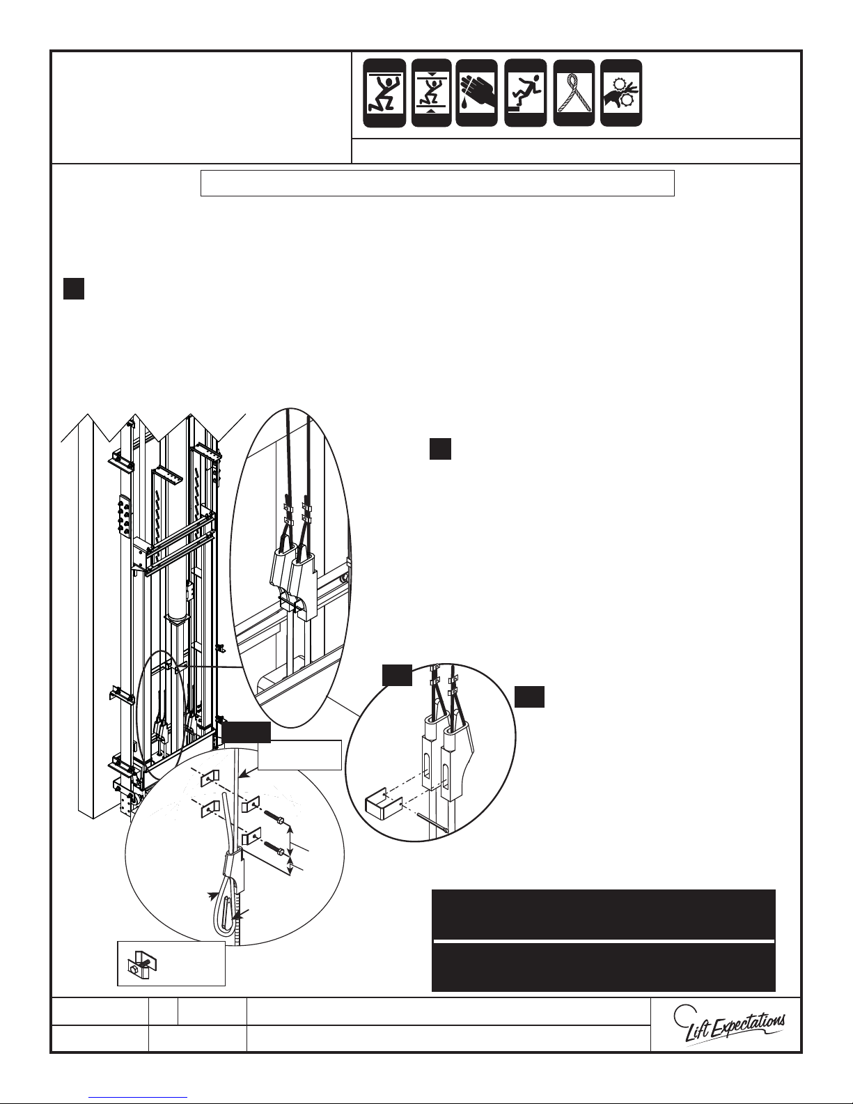
Note: The live side wire rope should be in line with the shackle rod.
Pull the slop out of the shackle springs on sling side and clamp in place.
6.
Note: Verify wire ropes are not crossed at any point throughout their complete length.
Route the wire rope through the shackle socket closet to the rail wall while pulling down on the wire rope
7.
to seat the shackle tightly in the pedestal base. Loop the wire rope up back through the shackle socket
while continuing to hold the tension on the wire rope. Insert the wedge into the newly formed loop and
pull on the dead end of the wire rope to seat the wedge into the shackle socket. Repeat this step for the
other shackle.
8.
9.
Verify the tension is equal on each wire rope and
adjust as needed.
Fasten (4) cable clamps into the designated
locations as described below:
A)
The rst clamp shall be placed a maximum
of 4 times the rope diameter above the
shackle.
(Example: 3/8” wire rope = maximum
distance of 1-1/2”)
DEAD SIDE
(NON LOAD
BEARING)
CABLE
CLAMP
ASSEMBLED
7, 9
LIVE SIDE
(LOAD BEARING)
B
WEDGE
A
3"
1-1/2"
10
B)
The second clamp shall be located within
8 times the rope diameter above the rst
clamp
(Example: 3/8” wire rope = maximum
distance of 3”)
Install the anti-rotation brackets into
10.
the shackles and secure.
Manually verify both safeties set simultaneously
before testing safeties with a full load.
Manually verify equal tension between wire
ropes and wire rope is clear of all obstructions.
PTM30179-D
09 MAR 2018
1726 North Ballard Road, Suite 1 - Appleton, WI 54911 - 920.991.9082
Technical Support 855.804.5774 - [email protected]
W
E
Page 31
CRUSH
Page 31
CRUSH
CUTTING
FALLING
KINK
PINCH
WIRE ROPE
INSTALLATION
BOLT
WASHER
ADJUSTMENT
NUT
WEDGE
SHACKLE
COTTER PIN
ANTI-ROTATION
CLIP
RUBBER
STOP
SPRING
PADDLE
WASHER
JAM NUTS
SHACKLE
BOLT
PADDLE
ECCENTRIC
ROLLER
SLING NOT SHOWN
FOR CLARITY
14, 16, 17
3-1/2" - 4-1/2"
T RAIL
SAFETY BLOCK
13
DIMPLE
PRE-SET
ADJUSTMENTS
ONLY!
DEPENDING ON
INSTALLATION
ADJUSTMENTS
MAY VARY!
RANGE
CRUSH
HAZARD
HAZARD
HAZARD
HAZARD
SERIES : 114
KNURLED WHEEL
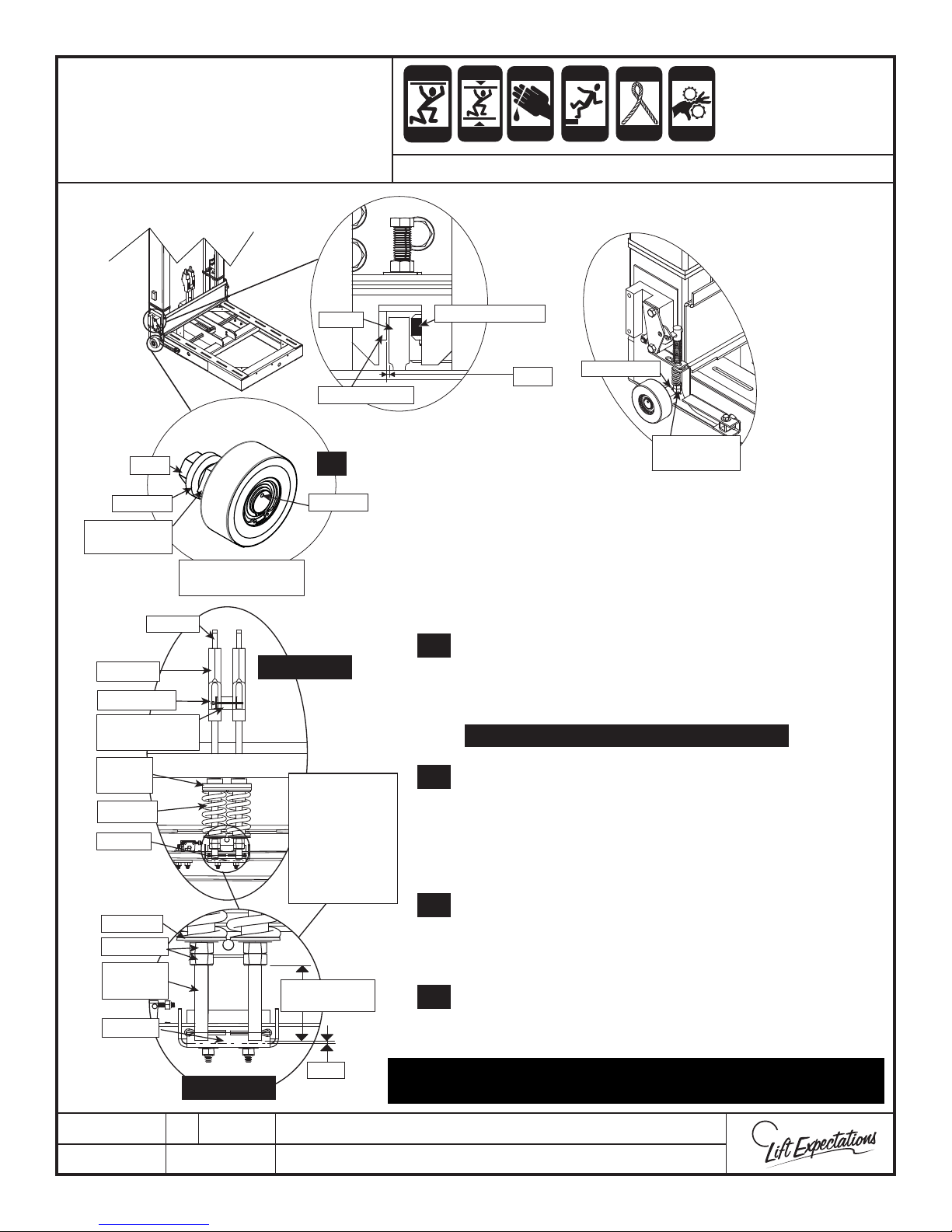
Verify safety assembly is free and not locked or jammed in
11.
place.
Using the pendant, move the elevator sling up so its hangs
12.
on the ropes.
Adjust the eccentric rollers until there’s a 1/32” gap
13.
between the rail and the safety. The eccentric wheels must
stay in the same plane with each other. Verify this with the
dimple on the end of the roller axel. Tighten the roller.
Rotate the paddle into place and reinstall the previously
14.
removed hardware through the safety actuator links and
square tube on both sides of the sling. Insert the bolts
from the to top.
Tighten the hardware.
15.
Measure the gap between shackle rod end and safety
16.
paddle. If its not 1/16” disassemble the safety actuator
links and square tube. Adjust the shackle rod nuts to move
shackle rod ends as needed to achieve the proper gap.
Use adjustment nuts if necessary to adjust safeties. When
17.
nished lock both jam nuts against each other. Verify
cotter pin is in place at the bottom of the rod and secured.
CRUSH
CRUSH
HAZARD
HAZARD
1/32"
HAZARD
CRUSH
HAZARD
HAZARD
COTTER PIN
CRUSH
HAZARD
HAZARD
ADJUSTMENT
NUTS
IMPORTANT: TORQUE BOLT TO 105 FT.-LBS.
1/16"
13, 16, 17
PTM30179-D
09 MAR 2018
Manually verify both safeties set simultaneously before testing
safeties with full load.
1726 North Ballard Road, Suite 1 - Appleton, WI 54911 - 920.991.9082
Technical Support 855.804.5774 - [email protected]
W
E
Page 32
W
E
CRUSH
Page 32
CRUSH
CUTTING
ECO-SYSTEM
ELECTRIC
FALLING
PINCH
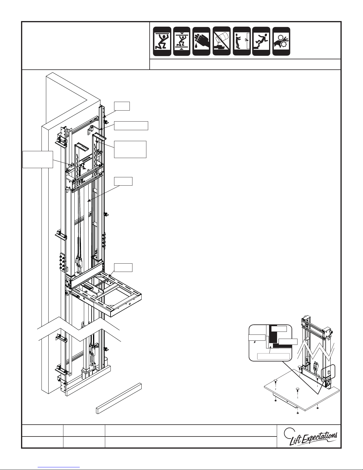
VERIFY JACK TRAVEL
Ram
Header
Rail
Final Limit
Cab
Stabilizer
Jack
CRUSH
HAZARD
HAZARD
CRUSH
HAZARD
HAZARD
CRUSH
HAZARD
HAZARD
HAZARD
HAZARD
HAZARD
CRUSH
HAZARD
HAZARD
SERIES : 114
Verify the sling does not collide, or come in contact with
1.
anything along travel of the elevator.
At the top landing check to see if you have 4” of over travel. At
2.
the bottom landing check to see if you have 2” of under travel.
If you do not have both, you need to adjust the rope length
and test again.
Verify the ram header always rides between the rails.
3.
If needed adjust the top nal to ensure proper operation.
4.
Bypass nal to verify jack will ring out before colliding with the
5.
ram header, coming o the rails, or striking the top of the
hoistway.
Locate the dead side of the wire rope, cut wire rope as close
6.
as possible above highest wire rope clamp at a perpendicular
angle and secure wire ropes together.
(Reference Proper Handling of Wire Rope page)
7.
TEST SAFETIES FOR PROPER OPERATION BEFORE
CONTINUING INSTALLATION.
Sling
Raise jack to full length of travel and check oil level in the
8.
pump with attached dip stick. Ensure oil level is maintained
between the indented marks provided on stick.
Note: It’s recommended the hydraulic oil level be
checked and maintained semi-annually.
To install the elevator car oor, follow the steps below.
9.
(Referenced from the Frameless Car Assembly page.)
10.
Place the oor on the sling. Run the elevator up verifying
clearance between car oor and all hoistway walls.
(Refer to eld drawings for details)
Walls on all cars except the
A.
Designer hang past the
car oor. Before fastening
oor to sling be sure to
SLING
WALL
FLOOR
allow enough clearance
between car oor and sling
CLEARANCE
back and cross members.
B.
Drill at least (4) holes and
bolt oor to sling
using provided hardware.
Note: If using the sling
extension, do not use
the holes in the sling.
PTM30178-C
06 MAR 2018
1726 North Ballard Road, Suite 1 - Appleton, WI 54911 - 920.991.9082
Technical Support 855.804.5774 - [email protected]
Page 33
CAR
Page 33
ANTI-
STATIC
CRUSH
CRUSH
CUTTING
ELECTRIC
FALLING
PINCH
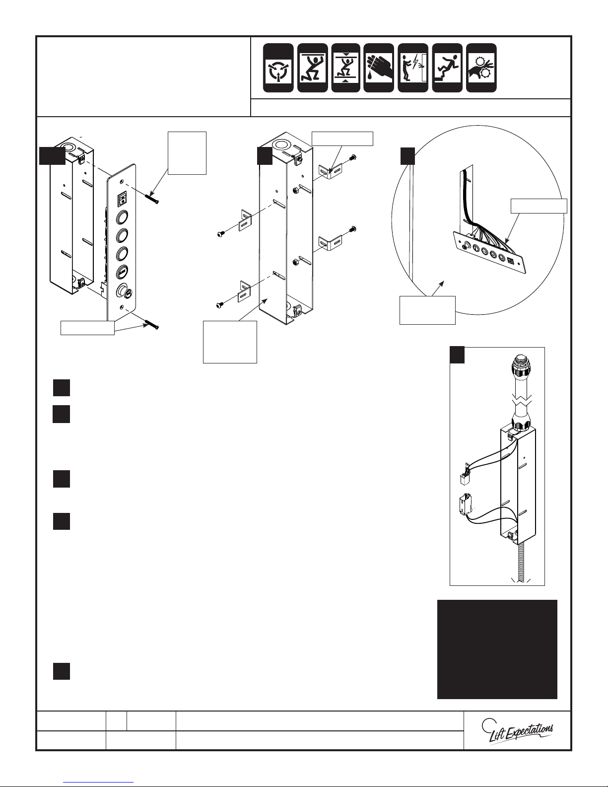
OPERATING PANEL
INSTALLATION
COP
1, 6 2
Screws x2 COP
Cover
Plate
Electrical
Box
SERIES : 008, 114 , 116, 118, 021, 022, 210
ALERT
CRUSH
HAZARD
HAZARD
Brackets x4
CRUSH
HAZARD
HAZARD
CRUSH
HAZARD
HAZARD
HAZARD
4
Elevator
Car Wall
HAZARD
3
CRUSH
HAZARD
HAZARD
COP Panel
1 Remove screws from COP and place in a safe place.
1.
2. Locate COP hole in the elevator car wall and measure the wall thickness.
2.
Place the COP brackets in position on the COP electrical box. O set the
brackets from the front edge of the COP electrical box by the distance
measured. Fasten the (4) COP brackets to COP electrical box with the
following provided hardware.
For elevator series 114, 021 and 022 route slack cable ex into the
3.
bottom of the COP box and fasten. Connect (2) slack cable plugs together
inside the COP box. The 2x4 enclosure should hang below the elevator car.
4. Slide COP cover plate through the COP hole in the elevator car wall.
4.
Be careful not to scratch any surfaces or pull out any factory wires.
5. Place COP enclosure with secured brackets into COP hole and fasten to wall
using the provided hardware.
Note: The installer may have to square o the corners or weld spots of the
COP hole in the elevator car wall to t the COP enclosure properly. While
doing this verify the interior of the elevator car wall is not being damaged or
accidentally making the COP hole larger than it should be.
Verify that the provided screws do not pierce through the interior wall of
the elevator car.
6.
6 Fasten COP cover plate onto COP enclosure with previously removed screws.
NOTE:
Some wires not shown
for clarity. Install prior
to car wall installation.
Slack cable plugs
contained in the COP are
only used for Series 114,
021 & 022 units.
PTM30045-F
22 FEB 2018
1726 North Ballard Road, Suite 1 - Appleton, WI 54911 - 920.991.9082
Technical Support 855.804.5774 - [email protected]
W
E
Page 34
WALL MOUNT
Page 34
TELEPHONE JACK
ANTI-
STATIC
ALERT
SERIES : All Elevators
CRUSH
CRUSH
HAZARD
HAZARD
CRUSH
CRUSH
HAZARD
HAZARD
CUTTING
CRUSH
HAZARD
HAZARD
ELECTRIC
HAZARD
FALLING
HAZARD
PINCH
CRUSH
HAZARD
HAZARD
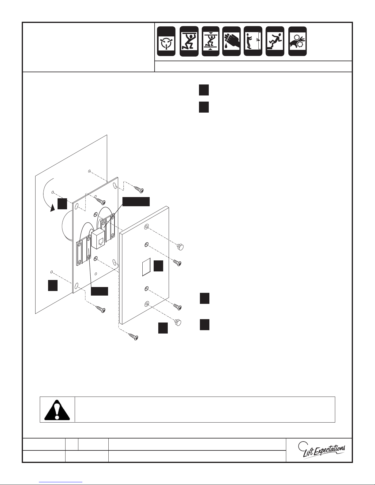
Locate the telephone jack Inside
car at a convenient location or as
directed by local codes.
INSIDE OF CAB WALL
CUT HOLE SLIGHTLY SMALLER
THAN PHONE JACK
1
GREEN
7
2
RED
1 Drill 1” opening in car wall.
1
2
2 Mark and drill (4) 1/16” pilot holes.
3 ALL OTHER LIST SERIES - Run wire
from the wall mount telephone jack
(red & green wires) to the phone (PH)
terminals in the car top box. Do not
route over high voltage wires.
4 Connect shielded travel cable wires
to phone (PH) terminals in the car
top box.
5 Connect the other end of the
shielded pair to the phone terminals
in the controller.
6 These terminals should then be
connected to the central telephone
exchange connection (by others) in
the machine room.
7
7 Secure plate cover with provided
screws.
Install the phone in the elevator before it is released to the customer!
PTE10017-B
05 APR 2017
8
8
1726 North Ballard Road, Suite 1 - Appleton, WI 54911 - 920.991.9082
Technical Support 855.804.5774 - [email protected]
8 Insert appropriate shoulder screws.
W
E
Page 35
CUTTING
Page 35
FALLING
PINCH
HANDRAIL
INSTALLATION
CRUSH
HAZARD
HAZARD
SERIES: ALL ELEVATOR
HAZARD
CRUSH
HAZARD
HAZARD
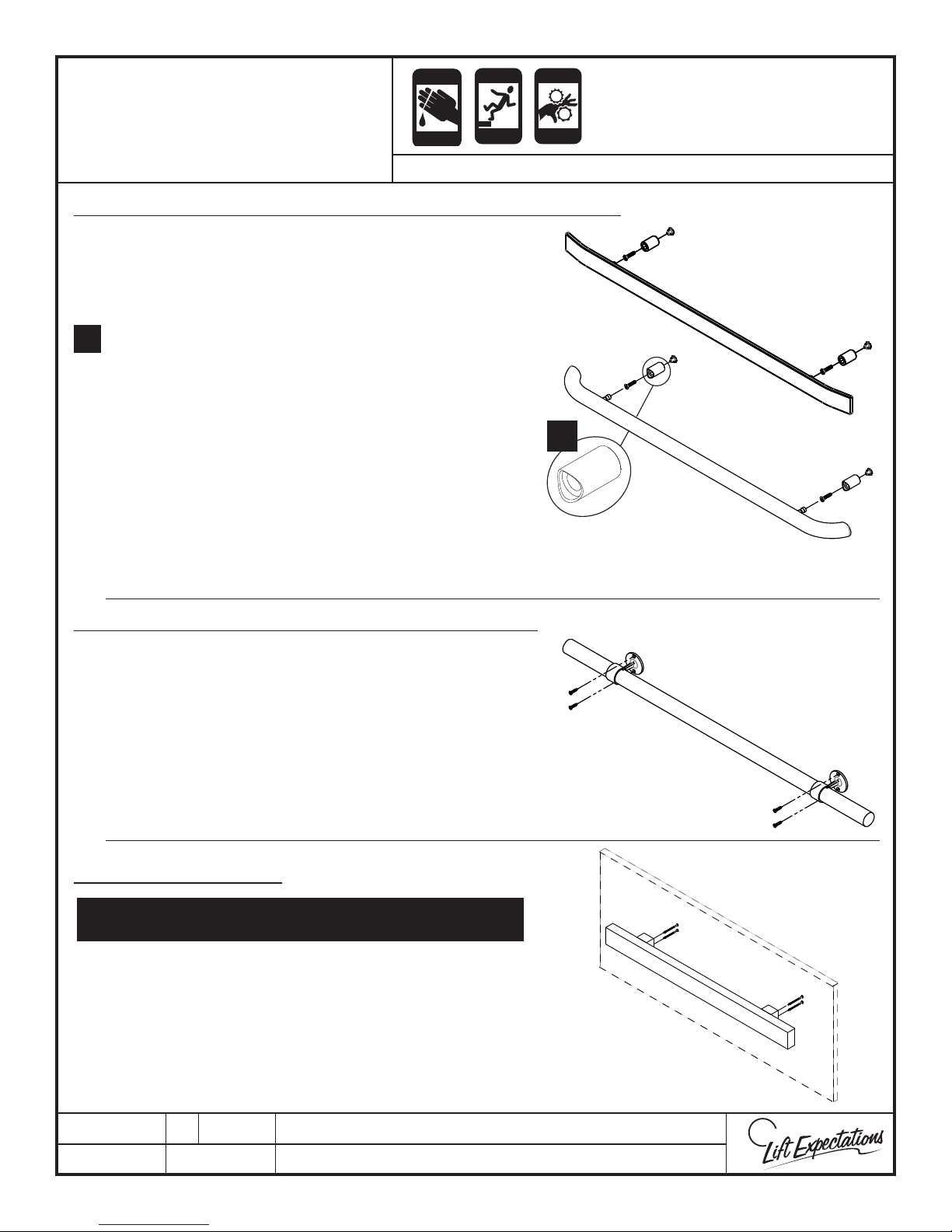
METAL ROUND or FLAT HANDRAIL with SPACER STANDOFFS
1. Locate stando spacer on appropriate wall
with the pre-drilled holes and fasten snuggly in
place with set screws facing downward. Then
loosen the set screws
2. Align the edges of the stando so its level.
2.
Verify the seams are free of gaps. Securely
fasten in place.
3. Align handrail with aluminum studs and press
into position on wall. Verify a tight t between
handrail and handrail spacer.
4. Securely fasten (2) 1/4” -20 x 1/4“ set screws in
place.
Note: Verify that both curved opening on the stando ’s a r e
lined up with the round handrail prior to installation.
2
WOODEN DOWEL HANDRAIL with RING STANDOFFS
1. Locate wall with pre-drilled holes for handrail.
2. Align handrail with fastening holes with set screws
facing downward.
3. Fasten handrail to wall with (4) 1” wood screws.
4. Lock handrail into position in stand o by fastening
(2) 8-32 x 3/16” set screws.
FLAT WOOD HANDRAIL
The at wood handrail needs to be fastened to the
back of the wall before cab assembly
1. Locate wall with pre-drilled holes for handrail.
2. Align handrail with fastening holes and fasten
handrail to wall with (4) #10 x 3” wood screws.
PTM30143-C
06 MAR 2018
1726 North Ballard Road, Suite 1 - Appleton, WI 54911 - 920.991.9082
Technical Support 855.804.5774 - [email protected]
W
E
Page 36
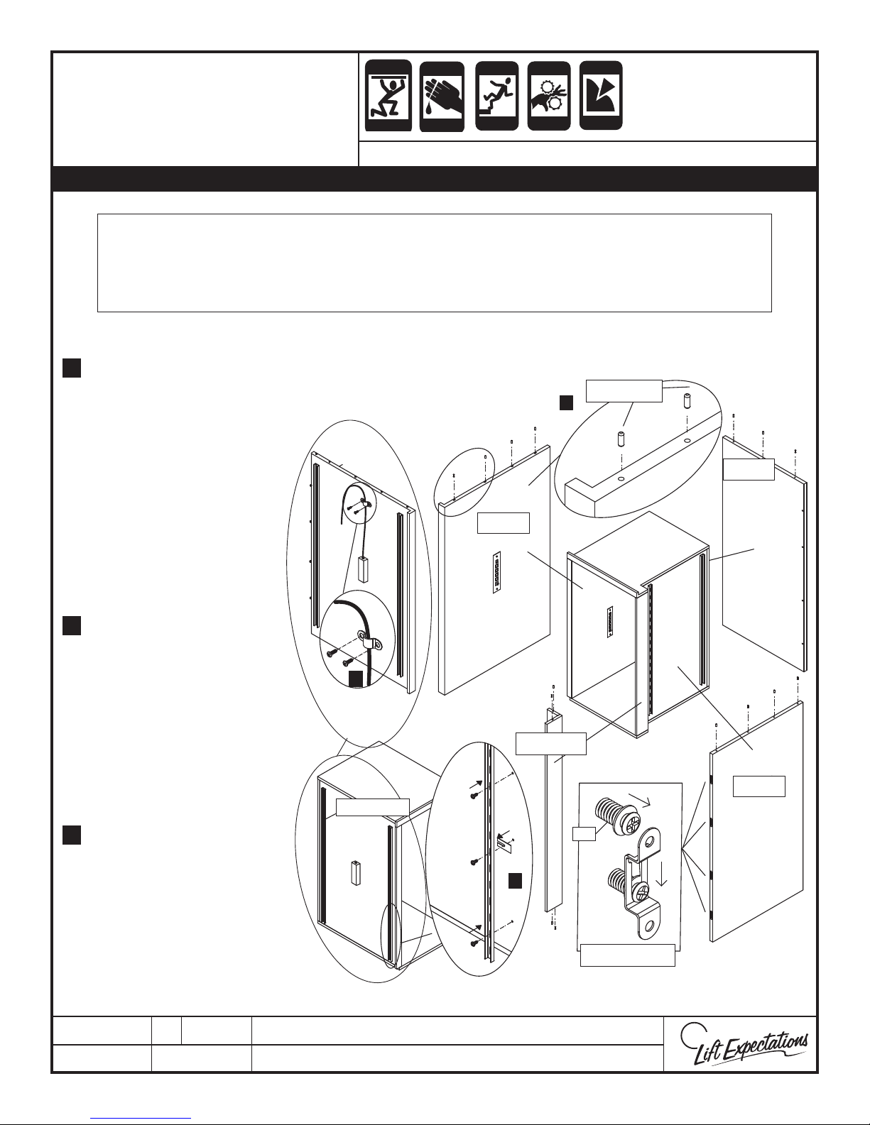
W
E
CRUSH
Page 36
CUTTING
FALLING
PINCH
PUNCTURE
FRAMELESS CAR
CRUSH
HAZARD
HAZARD
HAZARD
ASSEMBLY
CRUSH
HAZARD
HAZARD
SERIES : 021 - 022 - 114
Note: Mod-eez Pin may need to be tightened or loosened to achieve proper t between the cab walls.
ATTENTION
Verify clearance between car oor and all hoistway walls. Refer to eld drawings for details.
Individual car layouts may be di erent, however, always treat the rail wall as the B wall during
assembly. Verify handrail type. Flat wood handrails must be installed before car assembly
(Reference Handrail Installation page)
Insert provided dowels into
1.
pre-drilled holes along
the top of the walls (wall
B [or rail wall] will have
fasteners already attached
to the bottom). Insert
dowels into pre-drilled
holes along the top and
bottom of post(s) and
pocket(s) if provided, and
WALL
opposing wall if opposite
opening layout.
E
E
Warping before
2.
installation may occur. To
correct the warping, place
provided shims between
the outside wall and the
uni-strut as necessary to
correct the warp. Verify
the uni-struts are securely
fastened to the walls.
The COP must be installed
3.
into the wall prior to
car assembly. Using the
provided conduit clips &
hardware, secure the COP
conduit to the upper
outside car wall for easy
access during car top box
installation.
3
UNI-STRUT
CRUSH
HAZARD
HAZARD
POCKET
C
2
HAZARD
DOWELS
1
E
A
PIN
FASTENERS
WALL
F
C
B
D
WALL
B
PTM30162-C
29 MAR 2018
1726 North Ballard Road, Suite 1 - Appleton, WI 54911 - 920.991.9082
Technical Support 855.804.5774 - [email protected]
Page 37
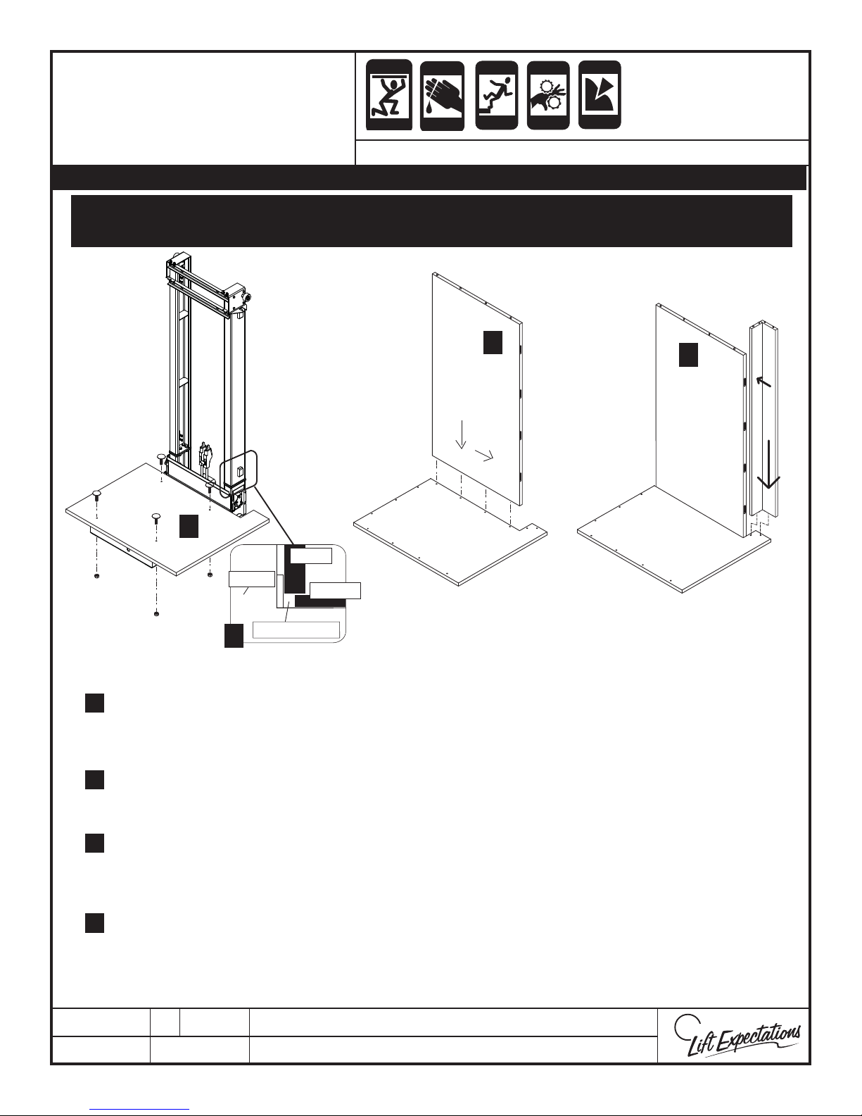
W
E
CRUSH
Page 37
CUTTING
FALLING
PINCH
PUNCTURE
FRAMELESS CAR
CRUSH
HAZARD
HAZARD
HAZARD
ASSEMBLY
CRUSH
HAZARD
HAZARD
SERIES : 021 - 022 - 114
Note: Mod-eez Pin may need to be tightened or loosened to achieve proper t between the cab walls.
Support walls during assembly. Tilting forwards or backwards on dowels could result in damage to the walls
and/or fasteners and prevent proper assembly of car.
CRUSH
HAZARD
HAZARD
HAZARD
6
7
B
B
5
WALL
SLING
FLOOR
CLEARANCE
4
Walls on all cars except the Designer hang past the car oor. Before fastening oor to sling be sure to
4.
allow enough clearance between car oor and sling upright.
A
A
C
Drill at least (4) holes and bolt oor to sling using provided hardware (Verify clearance between car
5.
oor and all hoistway walls. Refer to eld drawings for details).
Insert wall B [or rail wall] with fasteners onto oor A pins and slide into place (do not allow the wall to
6.
tilt forward or backward as this may cause damage).
Carefully place the gate pocket C with dowels into oor at the same time connecting the fasteners
7.
between B & C.
PTM30162-C
29 MAR 2018
1726 North Ballard Road, Suite 1 - Appleton, WI 54911 - 920.991.9082
Technical Support 855.804.5774 - [email protected]
Page 38
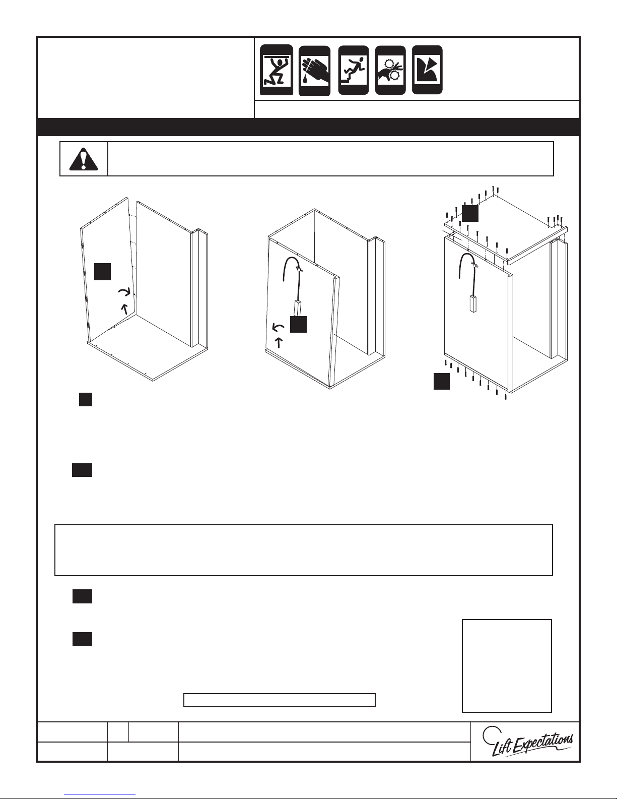
W
E
CRUSH
C
Page 38
CUTTING
FALLING
PINCH
PUNCTURE
FRAMELESS CAR
CRUSH
HAZARD
HAZARD
HAZARD
ASSEMBLY
CRUSH
HAZARD
HAZARD
SERIES : 021 - 022 - 114
Note: Mod-eez Pin may need to be tightened or loosened to achieve proper t between the cab walls.
Do not allow walls to slide o the oor this may cause harm to yourself and the walls.
CRUSH
HAZARD
HAZARD
HAZARD
D
B
D
8
B
C
E
C
10
A
A
Carefully lift at the connecting corner and connect
8.
the pins in wall D into the fasteners in wall B.
Drive dowels from oor A into wall D with a rubber
9.
mallet to prevent walls from moving or sliding.
Set wall E into place. Carefully lift wall E at the connecting
10.
10.
corner and connect the pins in wall E into the fasteners in wall D.
11.
Drive dowels from oor A into wall E with a rubber mallet to prevent walls from moving or sliding.
D
14
12
F
B
E
A
Verify ush alignment across top of walls and gate pocket. Use a rubber mallet to bring the walls into
alignment. Do not rely on ceiling screws to close gaps. Check to make certain all fasteners are seated
completely and all walls are level.
Set ceiling F onto walls B, C, D and E with dowels.
12.
13.
Use rubber mallet to drive dowels through the ceiling and into walls.
Fasten ceiling rst then oor panel to walls with provided hardware in
14.
pre-drilled locations.
VERIFY ALL FASTENERS ARE SECURE!
PTM30162-C
29 MAR 2018
1726 North Ballard Road, Suite 1 - Appleton, WI 54911 - 920.991.9082
Technical Support 855.804.5774 - [email protected]
Note:
Use a small
amount of wax
or liquid soap
for lubricating
hardware.
Page 39
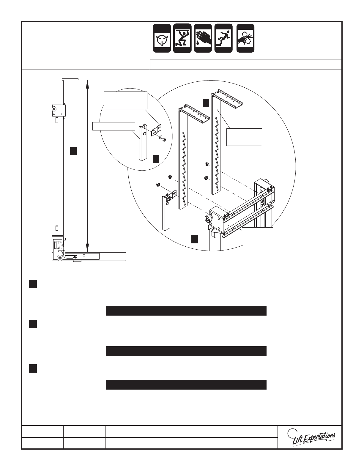
STABILIZER BRACKET
Page 39
INSTALLATION
TAPE READER
BRACKET
TAPE READER
4
ANTI-
STATIC
ALERT
CRUSH
CRUSH
HAZARD
HAZARD
CUTTING
HAZARD
SERIES : 114, 021, 022
3
CRUSH
HAZARD
FALLING
HAZARD
PINCH
CRUSH
HAZARD
HAZARD
2
STABILIZER
BRACKET
6
CROSS
4
1.
Move the elevator car to obtain access to the top of the elevator car.
Lower the right-side stabilizer bracket behind the sling. Align the stabilizer bracket with the cross-
2.
member bolts. With the cab stabilizer resting on the elevator car ceiling. Fasten the cab stabilizer with
MEMBER
3/8”-16 serrated ange nut. Repeat this step for the left side and only fasten the top 3/8”-16 serrated
ange nut.
TORQUE (4) 3/8”-16 SERRATED FLANGE NUTS TO 30 FT-LBS.
3.
Fasten tape reader on to tape reader bracket with a snug t but allowing it to oat with the
motion of the car using (1) - 3/8” at washer and (1) - 3/8”-16 nylock nut. Otherwise, noise will result
when the tape reader binds with the steel tape.
TORQUE (4) 3/8”-16 SERRATED FLANGE NUTS TO 30 FT-LBS.
Fasten assembled tape reader and tape reader bracket from step 5 to bottom left cross member using
4.
(1) - 3/8”-16 serrated ange nut.
TORQUE (4) 3/8”-16 SERRATED FLANGE NUTS TO 30 FT-LBS.
Square the elevator car to the oor landing opening. Mount the car stabilizers with 2 lag screws. (one
5.
per bracket) Verify elevator car clearances and openings to other oor landing openings within reason.
6.
Firmly secure elevator car to the stabilizers with provide hardware.
PTM30180-C
06 MAR 2018
1726 North Ballard Road, Suite 1 - Appleton, WI 54911 - 920.991.9082
Technical Support 855.804.5774 - [email protected]
W
E
Page 40
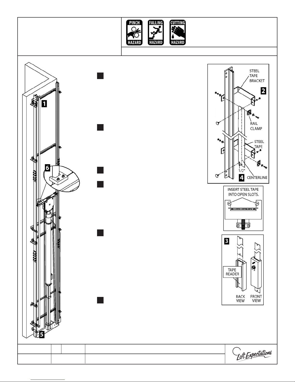
Steel Tape Installation
Page 40
At the highest position, clamp top bracket
1.
to left rail with the following hardware:
Attach steel tape to the top bracket with
2.
the following hardware and fasten:
3.
Feed tape through tape reader.
SERIES: 114
(2) - rail clips
(2) -1/2” -13 x 1-1/2” bolts
(2) - 1/2” at washers
(2) - 1/2” lock washers
(2) - 1/2” -13 nuts
(1) - 1/4” -20 x 3/4” elevator bolt
(1) - 1/4” at washer
(1) - 1/4” lock washer
(1) - 1/4” -20 nut
Attach and fasten steel tape to the bottom
4.
bracket before clamping the tape bracket
to the rail. Use the following hardware:
(1) - 1/4” -20 x 3/4” elevator bolt
(1) - 1/4” at washer
(1) - 1/4” lock washer
(1) - 1/4” -20 nut
Use the steel tape to locate the bottom bracket
5.
on rail. Pull tape down tightening steel tape (no
twisting or buckling) then fasten in place with
the following hardware:
(2) - rail clips
(2) -1/2” -13 x 1-1/2” bolts
(2) - 1/2” at washers
(2) - 1/2” lock washers
(2) - 1/2” -13 nuts
6.
Verify steel tape is in ram’s header tape guide.
PTM30175-B
27 FEB 2018
1726 North Ballard Road, Suite 1 - Appleton, WI 54911 - 920.991.9082
Technical Support 855.804.5774 - [email protected]
W
E
Page 41
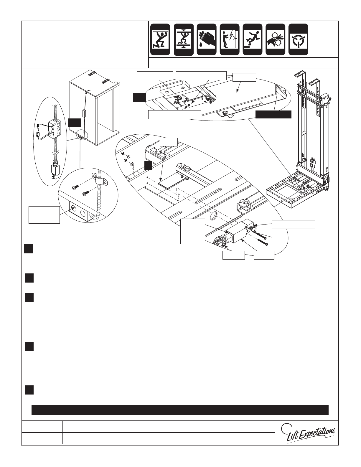
SLACK ROPE
Page 41
CRUSH
CRUSH
CUTTING
ELECTRIC
FALLING
PINCH
STATIC
ELECTRICITY
SAFETY WIRING
HAZARD
SERIES : 114, 021, 022
Reset Knob
4, 5
1/4-20 Set Screw
2, 3
CAM
1
Electrical
Box
1. Mount the slack cable into its location on the sling.
1.
Once the slack cable is mounted route the slack cable
harness to the COP location.
HAZARD
HAZARD
Adjustable CAM
Slack
Cable
Switch
HAZARD
Paddle
Fitting
HAZARD
Pinch Point
Cover
HAZARD
HAZARD
X
Actuator Arm
2. Remove 2” x 4” box cover and place conduit straps o to the side. Assemble the slack cable harness to the
2.
slack cable switch and mount 2” x 4” box under the elevator car oor.
3. Fasten the harness to the side of the car with a conduit strap. DO NOT pierce through the interior car walls.
3.
Connect the two connectors inside the electrical box and Fasten 2” x 4” cover onto box with previously
removed hardware.
Note: Verify the conduit will not be damaged by any object during the length of the elevators travel and
will also not to be damaged when the sling is sitting on the pit oor or mechanical stops.
4. Verify the switch contacts change state when switch arm is actuated from its NC state.
4.
If necessary, adjust actuator arm with 1/4”-20 set screw threaded in the adjustable CAM. Reset switch by
pulling the reset knob out. Thread the 1/4”-20 set screw in clockwise until the CAM actuates the switch and
thread the set screw back 1 full turn counter-clockwise.
5. Reset the slack cable switch by pulling the reset knob out. Pull the paddle down to ensure the slack cable
5.
switch actuates. Reset the slack cable switch.
DANGER: NEVER PULL THE PADDLE IN THE BACK WHERE THE SHACKLES WILL CRUSH YOUR FINGER(S)!
PTE10143-C
21 FEB 2018
1726 North Ballard Road, Suite 1 - Appleton, WI 54911 - 920.991.9082
Technical Support 855.804.5774 - [email protected]
W
E
Page 42
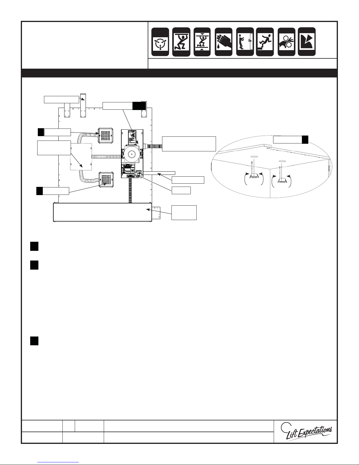
MODULAR WIRING
Page 42
CAR TOP LAYOUT
WARNING : ALL WIRING MUST MEET N.E.C. AND LOCAL CODES.
Sample Layout
Taper Reader
Cartop Box
LED Light
2
LED Light
Controller
ANTI-
STATIC
ALERT
CRUSH
CRUSH
HAZARD
HAZARD
CRUSH
CRUSH
HAZARD
HAZARD
SERIES : 008, 114, 115. 116, 118, 021, 022, 210
1, 4
Car Operating Panel
and Slack Cable
Travel Cable
CUTTING
CRUSH
HAZARD
HAZARD
ELECTRIC
HAZARD
FALLING
HAZARD
PINCH
CRUSH
HAZARD
HAZARD
LED Lights
PUNCTURE
HAZARD
2
LED Light
2
E-Stop
Auto
Gate
Locate the car top box as dictated by the lengths of the tape reader, light, and gate switch harness.
1.
Insert into appropriate receptacles in car top box.
To insert the LED lights, pull the springs back and insert through the holes from the inside of the elevator car.
2.
For more information reference the LED Light Installation manual.
Install the tape reader and the gate switch and/or autogate harness to car top box with the connectors and
3.
plug them into appropriate receptacles (reference Tape Reader Driver Board, Car Top Modular Wiring
schematics and Auto Gate manual)
If provided, plug the auto gate plug(s) into plugs based on gate usage below:
AG1: Primary Gate
AG2: Secondary Gate
AG3: Tertiary Gate
4.
Anchor car top box and LED light covers with provided hardware.
5.
Install travel cable, COP, phone and slack cable switch harness to car top box with the connectors.
Install the remaining plugs to the circuit board per Car Top Modular Wiring schematics.
6.
If provided, install the light curtain (reference Light Curtain Installation).
7.
If provided, the COP with Position Indicator (PI) will have one additional plug extending from the COP
8.
harness.
PTE10033-I
12 FEB 2018
1726 North Ballard Road, Suite 1 - Appleton, WI 54911 - 920.991.9082
Technical Support 855.804.5774 - [email protected]
W
E
Page 43
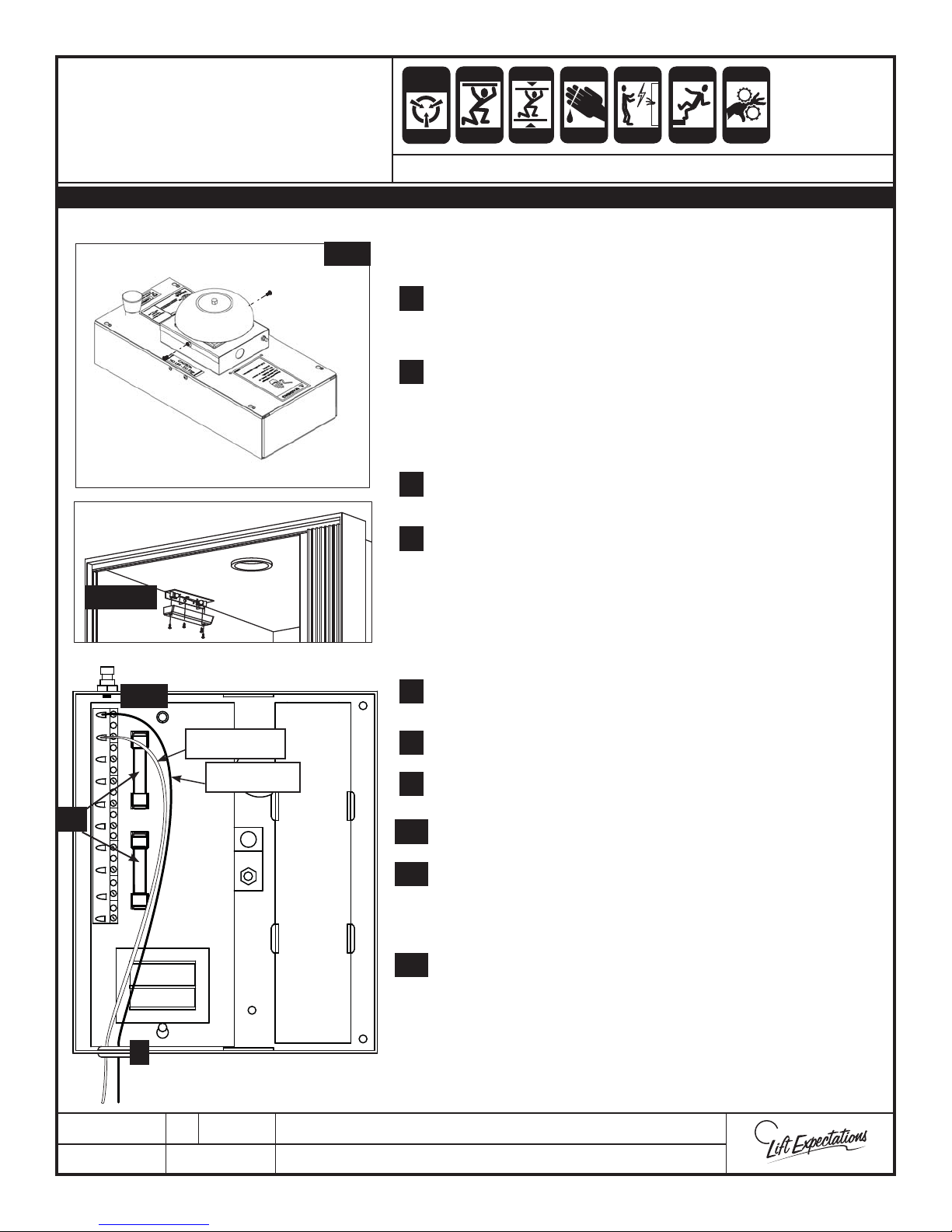
EMERGENCY LIGHT AND
Page 43
FUSE INSTALLATION
VERIFY POWER IS “OFF” AT THE CONTROLLER AND DISCONNECT!
2, 12
ANTI-
STATIC
ALERT
SERIES : 008, 114, 115, 116, 118, 021, 022, 210
CRUSH
CRUSH
HAZARD
HAZARD
CRUSH
CRUSH
HAZARD
HAZARD
CUTTING
CRUSH
HAZARD
HAZARD
ELECTRIC
HAZARD
FALLING
HAZARD
PINCH
CRUSH
HAZARD
HAZARD
1. Place car top assembly on the top of the car and center
(Reference Modular Wiring Car Top Page)
2. Remove cover with alarm bell attached by removing (2) sheet
2.
metal screws and placing to the side for use later
*If COP has a built-in e-light, skip to step 11
3. Remove black and white emergency light wires from the
3.
terminal block.
Note: The location of the wires and slide through the bushing
on the box.
4. Remove light cover by removing (2) pan head screws and
4.
place o to the side for use later.
11
4, 5, 8, 9
3, 10
White Wire
Black Wire
5. Place light against the interior car wall and ceiling to
5.
determine location.
6. Remove light and mark wire location on wall or ceiling
depending on chosen mounting position, and drill 1/4” hole
through on mark. Verify the wire length is long enough to
reach the alarm box.
7. Feed emergency light wires through 1/4” hole to alarm box
7.
and through the bushing into the alarm box.
8. Fasten light xture into place with appropriate hardware.
8.
9. Fasten cover to light xture with (2) pan head screws
9.
previously removed.
10.
10. Fasten black wire to terminal 1 and white wire to terminal 2.
11. Install (2) provided fuses into circuit board.
11.
Note: The battery will drain when the power is not supplied to
the unit.
12.
12. Fasten alarm cover onto box with (2) previously removed sheet
metal screws.
7
PTE10043-F
12 FEB 2018
13. Finish car top wiring and elevator installation. When the
installation is complete press the test switch to test light
operation. Allow up to 10 hours for battery to charge before
testing.
1726 North Ballard Road, Suite 1 - Appleton, WI 54911 - 920.991.9082
Technical Support 855.804.5774 - [email protected]
W
E
Page 44
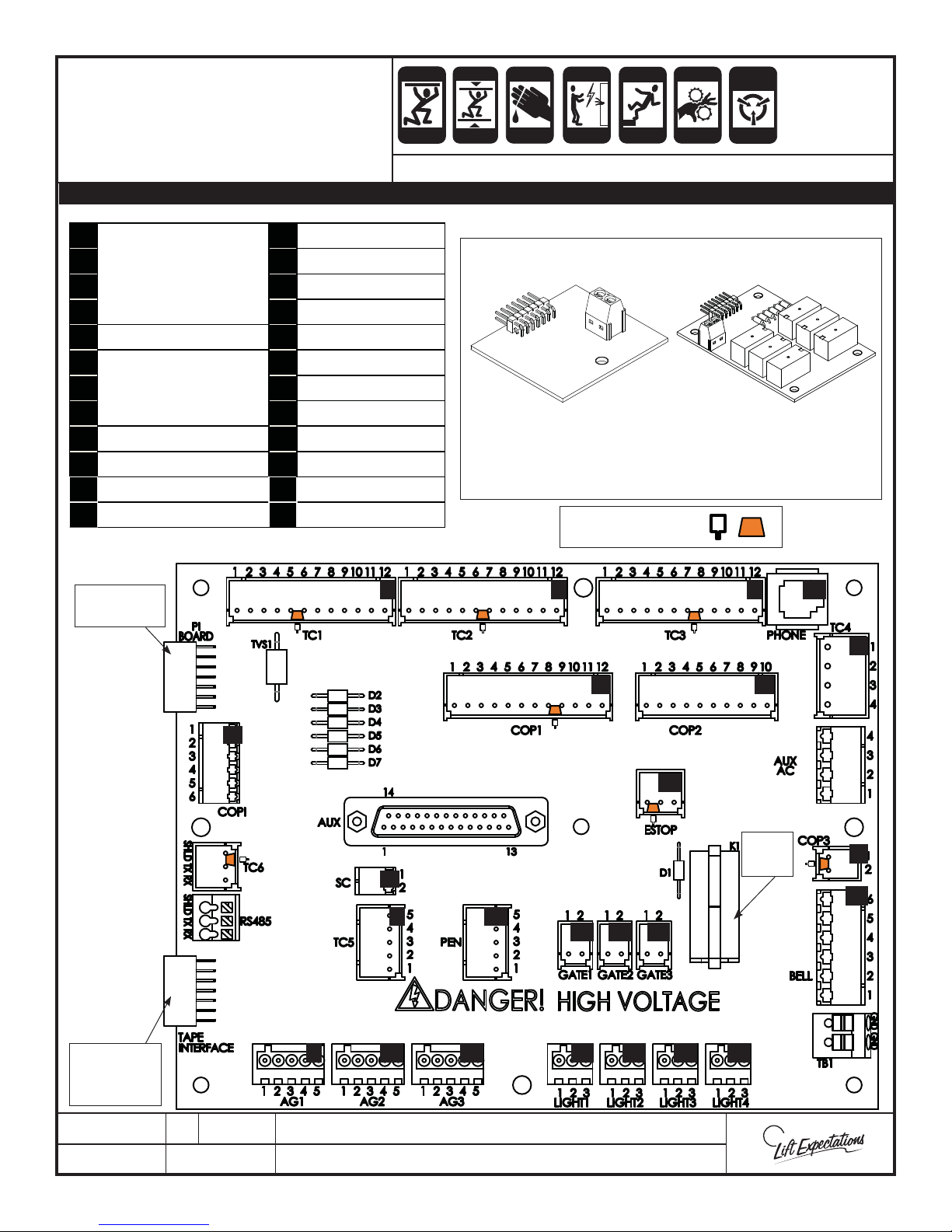
CAR TOP MODULAR
Page 44
WIRING
Note: Depending on the application not all plugs may be used.
CRUSH
CRUSH
HAZARD
HAZARD
CRUSH
CRUSH
HAZARD
HAZARD
CUTTING
CRUSH
HAZARD
HAZARD
ELECTRIC
HAZARD
FALLING
HAZARD
PINCH
CRUSH
HAZARD
HAZARD
SERIES : 008, 114 , 115, 116, 118, 021, 022, 210, 311, 511
STATIC
ELECTRICITY
HAZARD
1
13 Gate Switch 2
214Gate Switch 3
Travel Cable Plugs
315Light 1
416Light 2
5
6
719Bell and E-Light
N/A
Car OperaƟ ng
Panel Plugs (COP)
17 Light 3
18 Light 4
820Emergency Stop
9 AutomaƟ c Gate 1 21 PosiƟ on Indicator
10 AutomaƟ c Gate 2 22 Slack Cable Switch
11 AutomaƟ c Gate 3 23 Phone Jack
12 Gate Switch 1 24 N/A
Board
1 2 3
Receptacle
Board Receptacle
Standard Optional
Cartop
Jumper
Circuit Board
Position
Indicator
Circuit Board
Symbols: Keys
23
4
Tape
Interface
Receptacle
PTE10020-H
14 DEC 2017
21
6
22
5
24
12 13 14
9 10 11
1726 North Ballard Road, Suite 1 - Appleton, WI 54911 - 920.991.9082
Technical Support 855.804.5774 - [email protected]
15 16 17 18
20
7
Light
Relay
W
8
19
E
Page 45
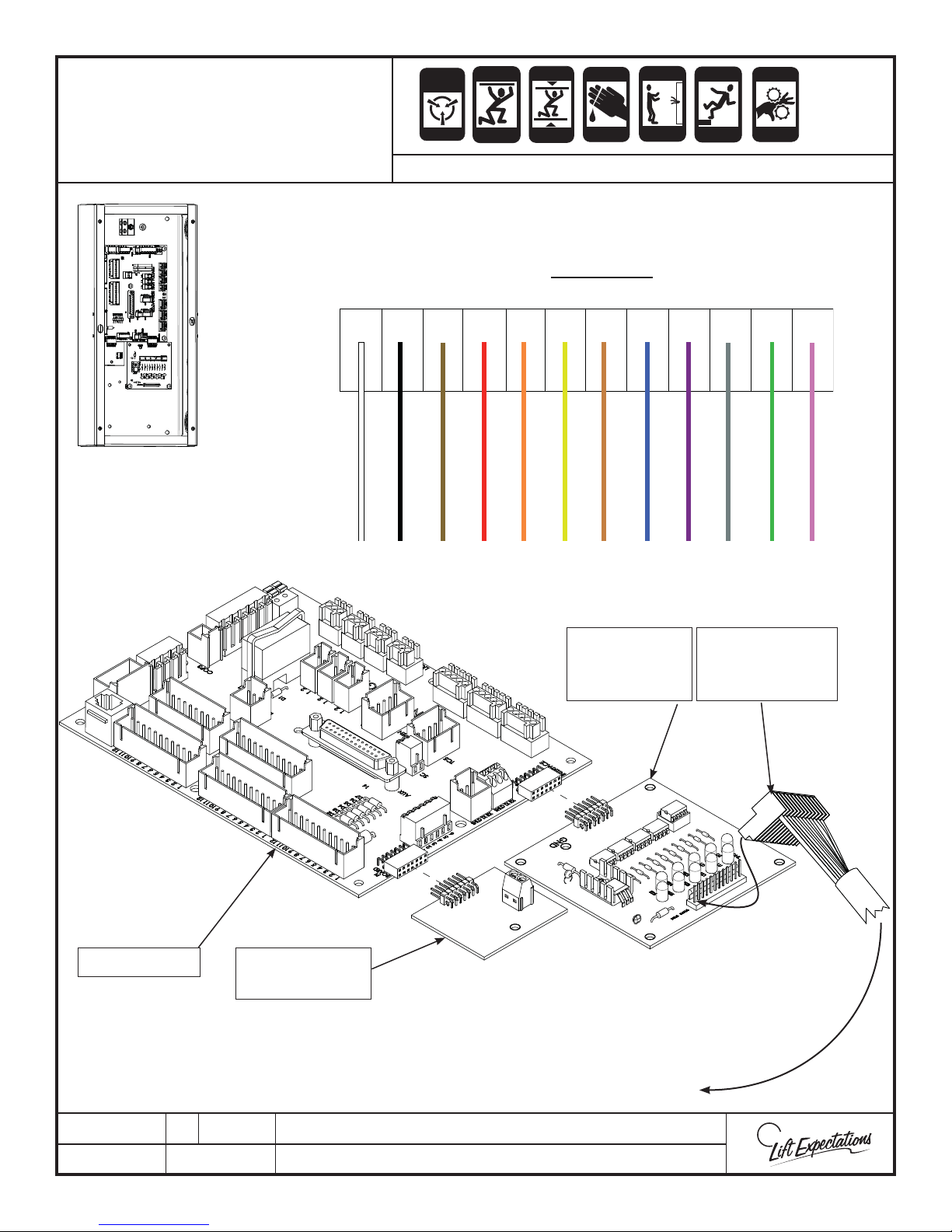
Tape Reader Interface
Page 45
Board Connectons
ANTI-
STATIC
ALERT
Series: 008, 114, 115, 116, 118, 021, 022 , 210, 311, 511
CRUSH
CRUSH
HAZARD
HAZARD
CRUSH
CRUSH
HAZARD
HAZARD
CUTTING
CRUSH
HAZARD
HAZARD
ELECTRIC
HAZARD
FALLING
HAZARD
Top of Plug
Verify the Wire Colors
PINCH
CRUSH
HAZARD
HAZARD
-24 +24 NA DZ LU EZ1 EZ2 EZ3 EZ4 EZ5 EZ6LD
Black
Brown
White
Orange
Red
Yellow
Blue
Tan
Tape Reader
Interface
Circuit Board
Violet
Grey
Green
Plug
(White wire ts
to the rst pin)
Pink
Car Top Board Standard
Circuit Board
PTE30185-B
06 AUG 2018
1726 North Ballard Road, Suite 1 - Appleton, WI 54911 - 920.991.9082
Technical Support 855.804.5774 - [email protected]
W
r
e
d
a
e
R
e
p
a
T
e
h
T
o
T
E
Page 46
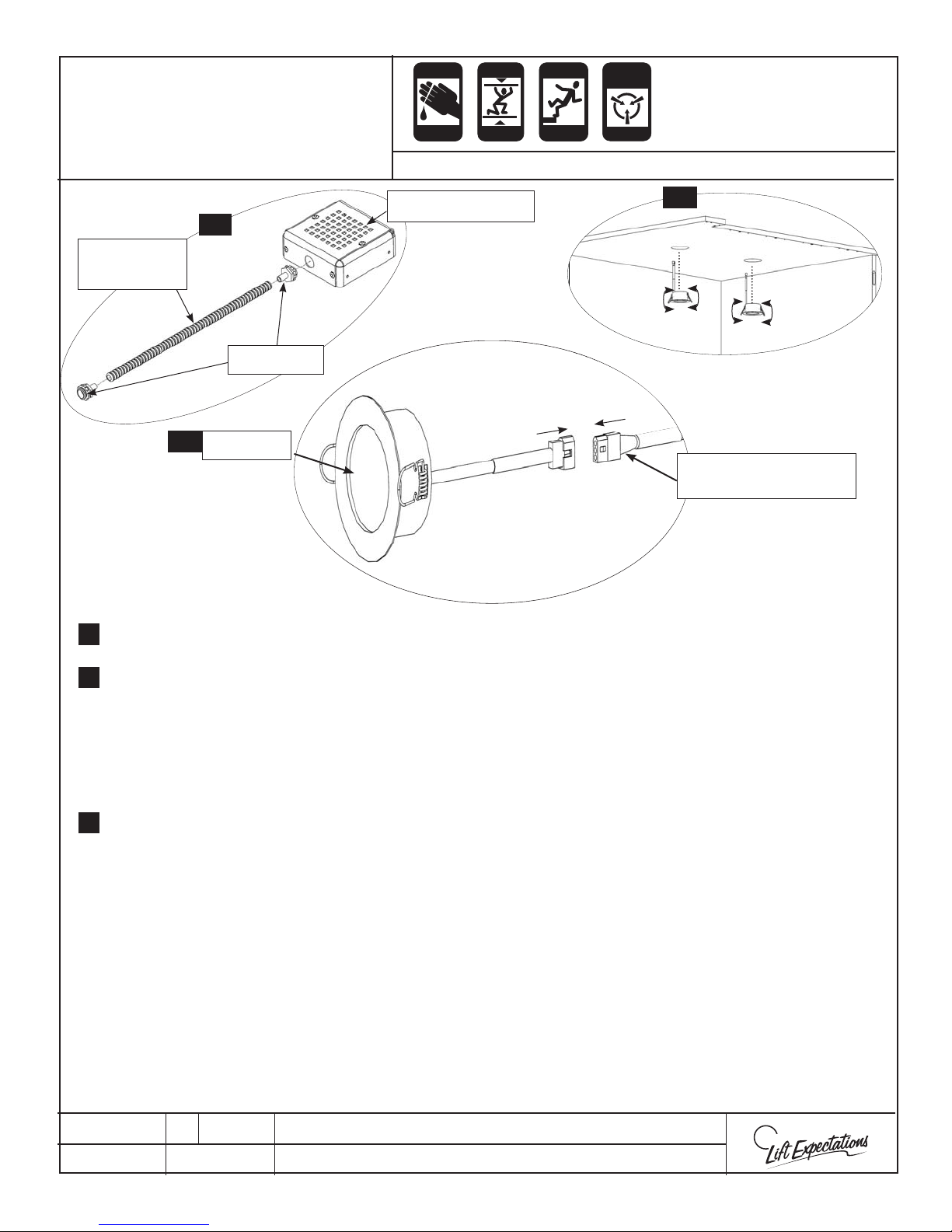
CUTTING
Page 46
CRUSH
FALLING
ANTI-
STATIC
LED Light Installation
1
Flexible
Conduit
Connector
4
LED Light
CRUSH
HAZARD
HAZARD
CRUSH
HAZARD
HAZARD
HAZARD
ALERT
Series: 008, 021, 022, 114, 115, 116, 118, 210
LED Light Cover
2
LED Extension Cord
(To LED light Controller)
1.
2.
3.
4.
5.
6.
Assemble all the LED light covers with the provided hardware.
Insert all the LED lights by pulling the springs back and feeding the plug and light through the
holes in the ceiling from the inside of the elevator car.
Place and temporarily secure the power supply on top of the elevator car in desired location.
Note: While securing anything to the elevator car, verify nothing punctures through to
the interior of the elevator car.
Plug the LED extension cords into the LED lights after the desired route has been laid out. Cut the
connector o the unused end of the LED extension cord. Next feed it through the conduit until
it reaches the power supply. If the LED extension cord needs to be shortened remove it from the
conduit and cut to the desired length. Finally feed the wire back through the conduit.
Note: Before cutting, verify you’re cutting the right end of the LED extension cords, have
enough extension cord to reach the LED light controller box and enough to for future
maintenance. ( Like changing out a light) You may need to supply your own exible
conduit if more than 18” is required.
Remove a knockout and connect the power supply to the car top with the provided conduit wire
harness. Wire per wiring schematic.
Knock out the holes required on the power supply for the LED lights and securely fasten the
loose whips of the LED light cover assemblies.
PTE10200-A
13 MAR 2018
1726 North Ballard Road, Suite 1 - Appleton, WI 54911 - 920.991.9082
Technical Support 855.804.5774 - [email protected]
W
E
Page 47
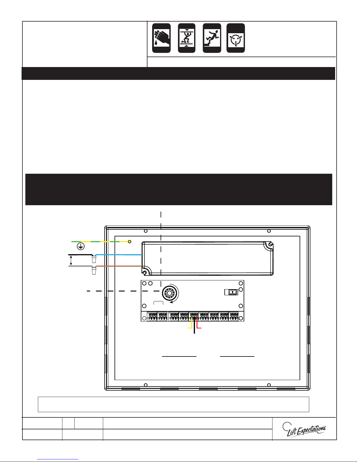
ANTI-
Page 47
STATIC
ALERT
LED Light Wiring
(With-out battery back up wiring)
CUTTING
CRUSH
HAZARD
HAZARD
CRUSH
CRUSH
HAZARD
HAZARD
FALLING
HAZARD
Series: 008, 021, 022, 114, 115, 116, 118, 210
ATTENTION: REMOVE ALL JUMPERS AS REQUIRED OUT OF THE LED LIGHT CONTROLLER BOX
WITHOUT BATTERY BACKUP WIRING
(STANDARD)
Strip the LED extension cord back to the desired length. Wire per LED light schematic and national
1.
and local codes terminating one LED light per terminal.
Verify that all LED lights work and adjust the dimmer to desired brightness.
2.
3.
Secure the LED Light covers and power supply to the ceiling of the elevator car with provided
hardware.
NOTE:
THERE ARE 9 SETS OF TERMINAL BLOCKS, EACH WITH 3 CONDUCTORS PER LIGHT. FOR SIMPLICITY, ONLY 1 SET IS SHOWN IN THIS
DIAGRAM. ALWAYS CONNECT ALL 3 WIRES (RED, BLACK, YELLOW), EVEN IF DIMMING IS NOT REQUIRED.
TO TURN LIGHTS ON AND OFF, SIMPLY ENERGIZE OR DE-ENERGIZE THE 120/240V AC INPUT TO THE EL2 POWER BOX.
Green & Yellow
120-240V
AC FEED
(Switched)
Black
White
Blue
Brown
Yellow Dim Control
DC Wiring
9
8
RED
RED
BLK
BLK
YEL
YEL
YEL
Black Dim Control
Power Supply
D
i
m
m
e
r
7
6
RED
RED
BLK
BLK
YEL
5
4
RED
RED
BLK
BLK
YEL
YEL
YEL
Red Dim Control
To Lights
3
RED
BLK
1
2
RED
RED
BLK
BLK
YEL
YEL
WARNING: DO NOT MIX AC AND DC WIRING. MAINTAIN BARRIER AS SHOWN BY THE DOTTED LINE
Input and output conductors are to be insulated for a minimum of 300V for all circuit connections.
PTE10200-A
13 MAR 2018
1726 North Ballard Road, Suite 1 - Appleton, WI 54911 - 920.991.9082
Technical Support 855.804.5774 - [email protected]
W
E
Page 48
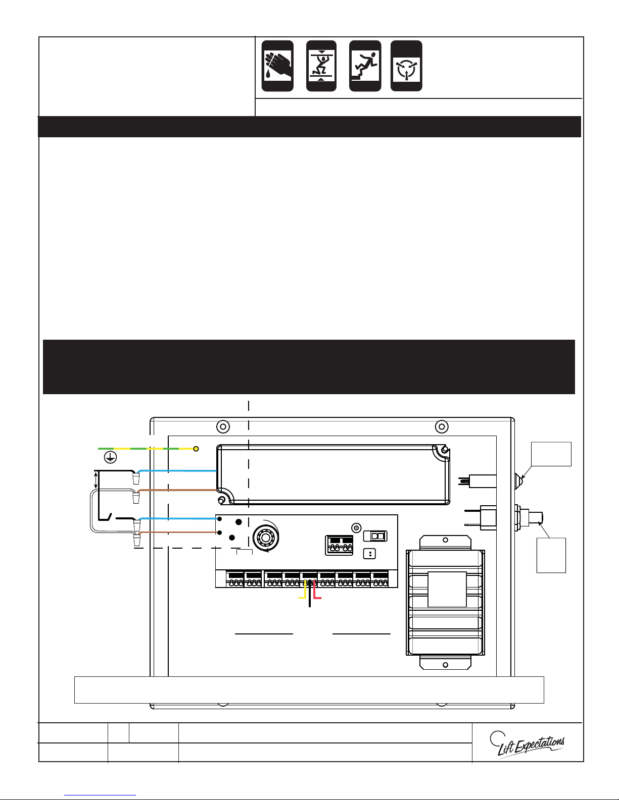
ANTI-
Page 48
STATIC
ALERT
LED Light Wiring
(With battery back up wiring)
CUTTING
CRUSH
HAZARD
HAZARD
CRUSH
CRUSH
HAZARD
HAZARD
FALLING
HAZARD
Series: 008, 021, 022, 114, 115, 116, 118, 210
ATTENTION: REMOVE ALL JUMPERS AS REQUIRED OUT OF THE LED LIGHT CONTROLLER BOX
WITH BATTERY BACKUP WIRING
(OPTIONAL)
Strip the LED extension cord back to the desired length. Wire per LED light schematic and
1.
national and local codes terminating one LED light per terminal.
Wire 2 LED lights to terminals 8 and 9 for emergency lighting. Wire per LED light schematic
2.
and national/local codes.
Verify that all LED lights work and adjust the dimmer to desired brightness.
3.
Secure the LED Light covers and power supply to the ceiling of the elevator car with provided
4.
hardware
When the installation is complete press the test switch to test light operation. Allow up to 10
5.
hours for a battery to fully charge before testing.
NOTE:
THERE ARE 9 SETS OF TERMINAL BLOCKS, EACH WITH 3 CONDUCTORS PER LIGHT. FOR SIMPLICITY, ONLY 1 SET IS SHOWN IN THIS
120-240V
AC FEED
(Switched)
DIAGRAM. ALWAYS CONNECT ALL 3 WIRES (RED, BLACK, YELLOW), EVEN IF DIMMING IS NOT REQUIRED.
TO TURN LIGHTS ON AND OFF, SIMPLY ENERGIZE OR DE-ENERGIZE THE 120/240V AC INPUT TO THE EL2 POWER BOX.
Green & Yellow
Black
White
Blue/ Hot
Brown/ Neut
Blue/ Hot
Brown/ Neut
9
8
RED
RED
BLK
BLK
BLK
YEL
YEL
YEL
Yellow Dim Control
Power Supply
D
i
m
m
e
r
7
6
5
4
RED
RED
RED
RED
BLK
YEL
BLK
BLK
YEL
YEL
YEL
Red Dim Control
Black Dim Control
To Lights
3
BLK
1
2
RED
RED
RED
BLK
BLK
YEL
YEL
Battery
Back
Up
Change
Indicator
Battey
Test
Switch
DC Wiring
WARNING: DO NOT MIX AC AND DC WIRING. MAINTAIN BARRIER AS SHOWN BY THE DOTTED LINE
Input and output conductors are to be insulated for a minimum of 300V for all circuit connections.
PTE10200-A
13 MAR 2018
1726 North Ballard Road, Suite 1 - Appleton, WI 54911 - 920.991.9082
Technical Support 855.804.5774 - [email protected]
W
E
Page 49
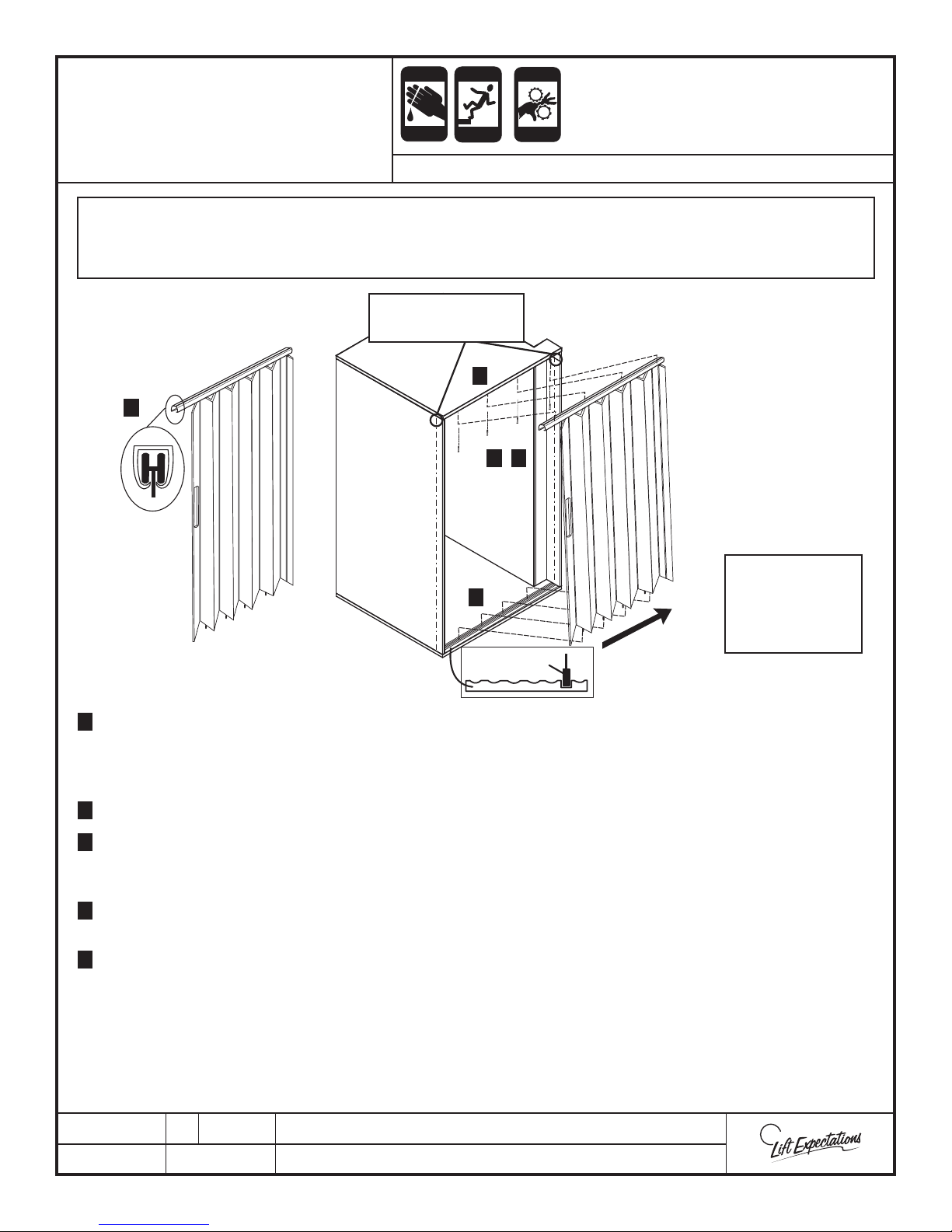
CUTTING
Page 49
FALLING
PINCH
ACCORDION GATE
INSTALLATION
CRUSH
HAZARD
HAZARD
HAZARD
CRUSH
HAZARD
HAZARD
SERIES : 008 -114- 115- 116 - 118 - 021 - 022 - 210
CAUTION : Over tightening top gate track screws may cause track to bend inward on the lead post of the
gate and cause added resistance, or fasteners may strip out in the ceiling. This may cause
problems when opening or closing the gate.
PLUMB LINES ON
INSIDE OF CAR
1
3
4 5
Reference Field
2
Drawings For
Gate Stack
FOLD GATE
Bottom
Gate Guide
1
1 Remove gate track from the ceiling panel. If necessary, place a mark on the sides of the track for a position locator
TOGETHER
to aid in alignment upon installation. Be careful not to mark in a noticeable location. Keep in mind the screw holes
in the ceiling may be used as locators. Since the track will be reinstalled using the same holes and screws maintain
gate track orientation. Place screws o to the side for use later.
2 Collapse gate and place the bottom guides into the oor track .
2
3
3 Stand gate upright while maintaining the gate stack in the correct orientation (locate handle on the strike side), and
slide the track onto the wheels; Lineup the wheels properly in the track grooves. Be careful not to slide the wheels
in sideways. If necessary, reference eld drawings for correct gate orientation.
4
4 Slide top of gate with gate track in place on the car ceiling in original factory location. Align the track in the same
place with the previously noted locators such as marks and/or hole locations for proper alignment.
5
5 Stack the gate to one end of the track (either side of the opening), and fasten the other end of the track to the
ceiling of the car using previously removed screws. Seat the screws rmly against the track resulting in full contact
between the track and the ceiling. Be careful not to bend the track. Fasten at all visible hole locations in track.
Slide the gate to the attached end of the track and nish fastening the track to the ceiling.
Location
6 Slide the gate back and forth along the track observing smooth operation. If gate does not slide smoothly check for
screw heads not fully seated, wheel not properly aligned, or dirt/debris in the track.
PTM30118-C
05 APR 2017
1726 North Ballard Road, Suite 1 - Appleton, WI 54911 - 920.991.9082
Technical Support 800.238.8739 - [email protected]
W
E
Page 50
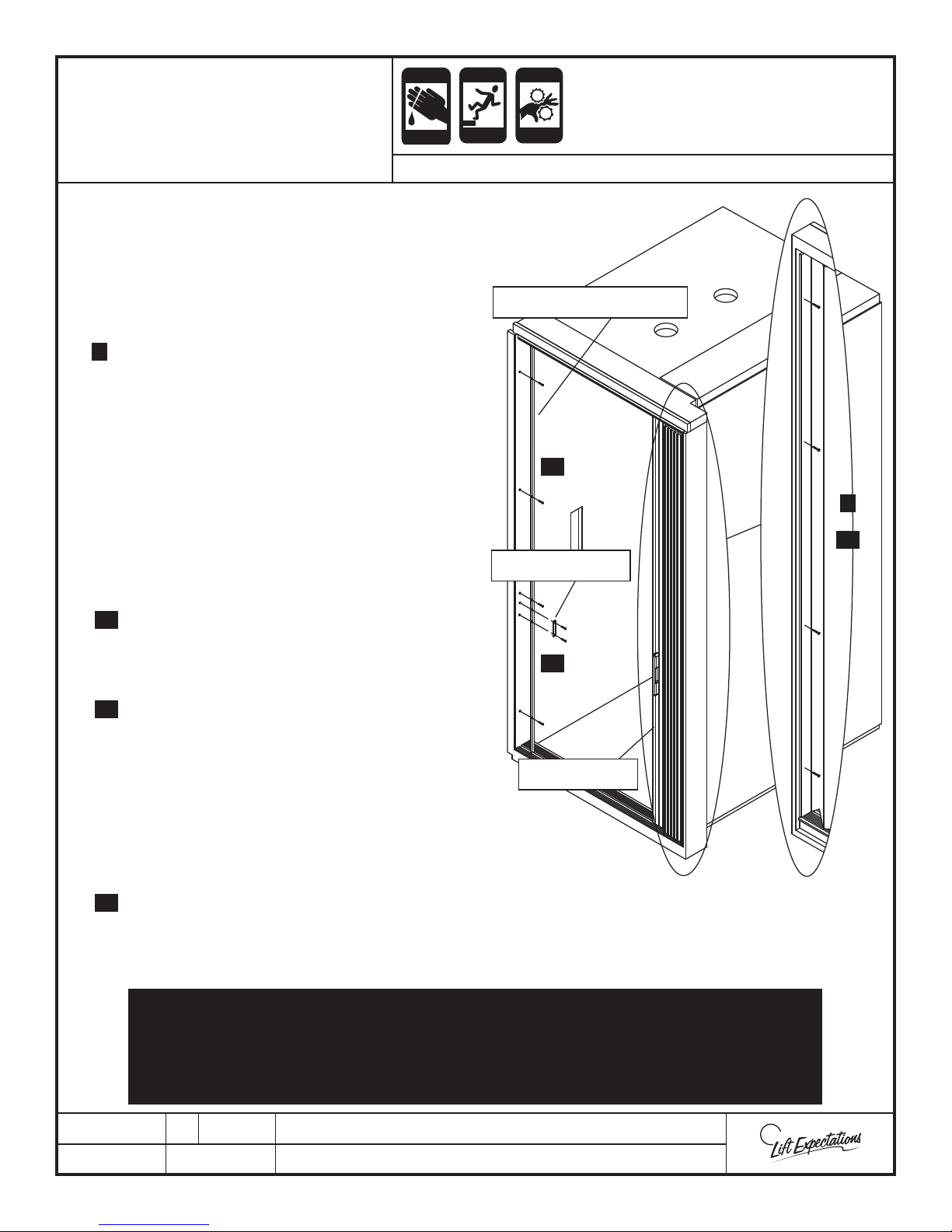
CUTTING
Page 50
ACCORDION GATE
CRUSH
INSTALLATION
7 Stand inside the car, and push the gate to the stack
side. Let the gate form its own plumb, and carefully
mark a line with a nonpermanent mark on the
wall/pocket/post at the edge of the mounting panel
near the top and bottom. It is important to make this
mark while the gate is in the stacked position.
8 Extend the gate to have access to the mounting panel.
8
Hold the mounting panel edge at the nonpermanent
marks. Note, the position of the mounting panel
may move away from the marks as the gate is
extended open. The panel position must be
maintained at the marked edge. Fasten mounting
panel in place with (2) - #6 x 1-1/2” at head screws
8” down from the ceiling and 8” up from the oor.
9 Stack the gate against the mounting panel to form a
neat, tight stack. Do not force the stack into position.
If gate stack binds, the mounting panel moved from
the marked edge, and the previous step needs to be
repeated.
HAZARD
HAZARD
SERIES : 008 -114- 115- 116 - 118 - 021 - 022 - 210
FALLING
HAZARD
PINCH
CRUSH
HAZARD
HAZARD
GATE STRIKE JAMB
11
STRIKE PLATE
8
10
10
10 Once the gate stacks properly, re-extend the gate and
fasten the mounting panel with (2) - #6 x 1-1/2” at
head screws between the rst (2) screws evenly
splitting the distance.
11 Dry t the gate strike jamb against the opposite wall
11
of the stack. The strike jamb needs to be centered
with the top gate track and the oor track groove.
Slide the gate lead post over to the strike to verify
proper placement. Fasten the gate strike jamb with
(4) - #6 x 1-1/2” at head screws.
13
LEAD POST
12 Center the strike plate on the magnet with the
adhesive side out. Remove the protective tape from
the adhesive backing, and push the door rmly shut.
13 Slide the gate open while pressing on the strike plate
13
with a small athead screw driver to maintain placement. Drill through the center of each strike plate screw hole and
gate strike jamb using a 3/32” drill bit. Fasten the strike plate in place with (2) - #6 x 1-1/2” at head screws.
14 If provided, install gate operator at this time (reference gate operator installation manual).
VERIFY ALL FASTENERS ARE SECURELY FASTENED. VERIFY THE GATE OPENS AND
CLOSES WITH SMOOTH OPERATION. THE GATE MUST STACK TIGHT IN THE OPEN
POSITION AND LATCH ON THE MAGNET WITH NO VISIBLE GAPS BETWEEN THE
GATE STRIKE AND LEAD POST.
PTM30118-C
05 APR 2017
1726 North Ballard Road, Suite 1 - Appleton, WI 54911 - 920.991.9082
Technical Support 800.238.8739 - [email protected]
W
E
Page 51

PAGE INTENTIONALLY LEFT BLANK
Page 51
Page 52
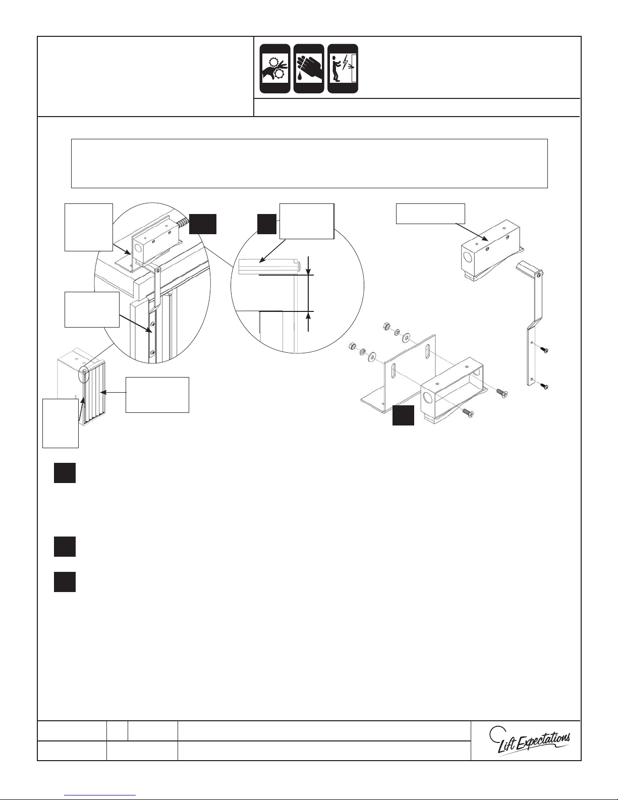
PINCH
Page 52
CUTTING
ELECTRIC
Frameless Car Gate
CRUSH
Switch Installation
HAZARD
HAZARD
Series: All
BEFORE INSTALLATION REFERENCE ASME A17.1/CSA B44 CODE
If Automatic Gate Operator is not provided, continue installation with the instructions provide below.
If Automatic Gate Operator is provided, follow the instructions provided with the Automatic Gate Operator.
CRUSH
HAZARD
HAZARD
NOTE:
HAZARD
Gate
Lead
Post
1.
Gate
Switch
1, 4
1
Actuator
Block
Gate Switch
Bracket
1 1/4”
to
Actuator
Arm
Accordion
Gate
1 1/2”
3
Place the actuator arm onto the lead post of gate, measure a 1 ¼” -1 ½” from the bottom of the cam to
the top of the trim and secure the gate switch actuator arm onto the gate lead post with the provided
hardware.
2.
Verify the gate switch is the correct hand for the gate.
Remove the cover of the gate switch and place the cover and screws aside and fasten the gate switch to
3.
the gate switch bracket with provided hardware.
With the gate closed, fasten the assembled gate switch and bracket to the top of the elevator car with
4.
provided hardware. Verify the gate actuator arm will actuates the gate switch.
NOTE: If the actuator arm does not activate the gate switch. To adjust the gate switch height by loosening the
hardware and moving the gate switch up and down to the desired position and tightening the hardware.
Open and close the gate to verify the gate switch actuates. Then hold the switch while opening and
5.
closing the gate verifying the gate arm will make the proper connection to the gate switch.
Replace the cover of the gate switch.
6.
PTM30113-D
16 MAR 2017
1726 North Ballard Road, Suite 1 - Appleton, WI 54911 - 920.991.9082
Technical Support 855.804.5774 - [email protected]
W
E
Page 53
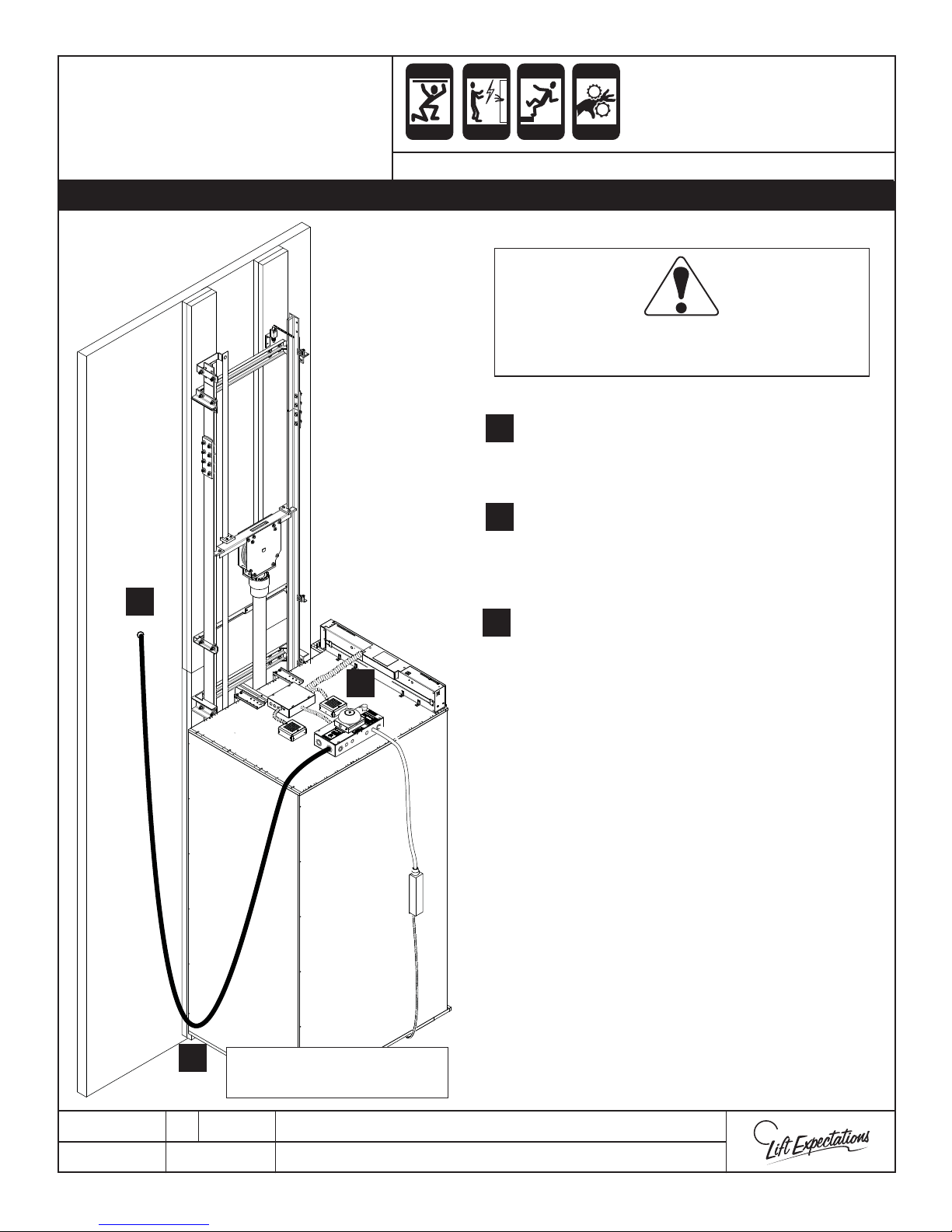
USE CAUTION
!!!! TO ENSURE CABLE WILL NOT CATCH ON OTHER COMPONENTS
Travel
Page 53
CRUSH
ELECTRIC
FALLING
PINCH
Cable
Installation
USE CAUTION
2
HAZARD
Series: All Elevators
!!!! TO ENSURE CABLE WILL NOT CATCH ON OTHER COMPONENTS
HAZARD
HAZARD
HAZARD
All Wiring and Strain Relief Must Meet
N.E.C. and Local Code Requirements.
1. Plug cable into the car top box and
1.
anchor to the top of elevator car with strain
relief.
2. In the hoistway, securely anchor the travel
2.
cable with strain relief approximately 2 feet
above the midpoint of travel with the elevator
car at the lowest oor landing.
3. Double check that the traveling cable hangs
3.
freely so it does not catch on any part of the
elevator car or any item mounted in the
1
1
hoistway. Run the elevator though its
complete travel range, including over and
under travel, to verify that the traveling cable
moves gracefully and does not get caught
on any part of the elevator car or any item
mounted in the hoistway. Verify as it moves
that it does not pull on the strain relief anchor
points. Adjust as necessary.
3
SERIES 114 SHOWN FOR
ILLUSTRATIVE PURPOSES
PTM30225-A
23 JAN 2018
Note: Ensure traveling cable can not be
crushed when resting on mechanical stops.
4. Route travel cable to the controller.
All wiring must meet N.E.C. and local code
requirements.
1726 North Ballard Road, Suite 1 - Appleton, WI 54911 - 920.991.9082
Technical Support 855.804.5774 - [email protected]
W
E
Page 54
TRAVEL CABLE TO
Page 54
CRUSH
CUTTING
ELECTRIC
FALLING
PINCH
STATIC
ELECTRICITY
CONTROLLER WIRING
Travel Cable Wires Terminals Travel Cable Wires Terminals
11F 21EZ4
22F 22EZ3
33F 23EZ2
44F 24EZ1
55F 25LD
66F 26LU
7FC 27DZ
8 1A 28 NOT USED
HAZARD
SERIES : 114 , 116
HAZARD
HAZARD
HAZARD
HAZARD
HAZARD
9 2A 29 +24
10 3A 30 -24
11 4A 31 AG1
12 5A 32 AG2
13 6A 33 AG3
14 AC Purple 14 Gauge AUX
15 ESTOP White 14 Gauge NEUT
16 SC Black 14 Gauge LT
17 LITE Green 14 Gauge GRD
18 GATE Shielded Red PHONE
19 EZ6 Shielded White PHONE
20 EZ5
PTE30186-A
06 JAN 2018
1726 North Ballard Road, Suite 1 - Appleton, WI 54911 - 920.991.9082
Technical Support 855.804.5774 - [email protected]
W
E
Page 55
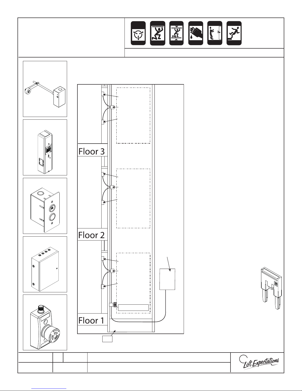
HOISTWAY WIRING
Page 55
LAYOUT
ANTI-
STATIC
ALERT
CRUSH
CRUSH
HAZARD
HAZARD
CRUSH
CRUSH
HAZARD
HAZARD
CUTTING
CRUSH
HAZARD
HAZARD
SERIES : 008 , 114, 021, 022, 115, 116, 118, 210
ELECTRIC
HAZARD
FALLING
HAZARD
GAL Interlock
EMI Interlock
Hallstation
This illustration is an example of cable layout with the least voltage drop throughout
the circuit.
INTERLOCK
Notes:
JUNCTION BOX
HALL STATION
• High voltage and low voltage
must run separate and only cross
over perpendicular to each other.
• Disconnect power to the elevator
before wiring these components.
• Be warned of the potential for
personal injury if you are no
INTERLOCK
JUNCTION BOX
careful.
• Do not route wires across landing
face walls.
HALL STATION
• All wiring must meet N.E.C. and
local codes.
Controller Box
Pit Switch
PTE10035-D
31 JAN 2018
• Use 18 gauge stranded low
voltage wiring other than
provided harnesses.
• Refer to proper pages for
CONTROLLER
INTERLOCK
JUNCTION BOX
individual component
installation.
• If the unit that you are
working on is equipped
HALL STATION
with EMIjumper is installed
between DC and DL
in the controller.
PIT SWITCH
PIT
1726 North Ballard Road, Suite 1 - Appleton, WI 54911 - 920.991.9082
Technical Support 855.804.5774 - [email protected]
III’s be sure the
W
E
Page 56
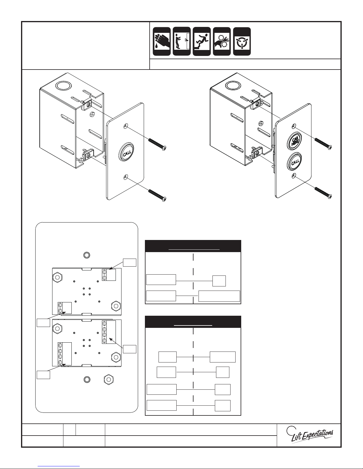
HALL STATION WIRING
Page 56
AND INSTALLATION
CRUSH
HAZARD
ELECTRIC
HAZARD
CUTTING
HAZARD
SERIES : ALL
FALLING
HAZARD
PINCH
CRUSH
HAZARD
HAZARD
STATIC
ELECTRICITY
HAZARD
TB2
TB2
COM N/O N/C LMP
COM N/O N/C LMP
TB1
COM N/O N/C LMP
COM N/O N/C LMP
TB1
Car Here Light
Hall Station
Terminals
TB1/LMP
TB2/LMP
Call Button
Hall Station
Terminals
N/O
COM
TB1/LMP
TB2/LMP
Controller
Terminals
EC
EMI 1- EMI 6
Controller
Terminals
1F-6F
FC
IU1
IU2
Install hall station
1.
boxes.
Wire hall station per
2.
schematic.
Fasten hall station
3.
plate onto box with
provided hardware.
Do not allow any of
the wires to become
cut or pinched by the
cover.
PTE10058-D
29 JAN 2018
1726 North Ballard Road, Suite 1 - Appleton, WI 54911 - 920.991.9082
Technical Support 855.804.5774 - [email protected]
W
E
Page 57
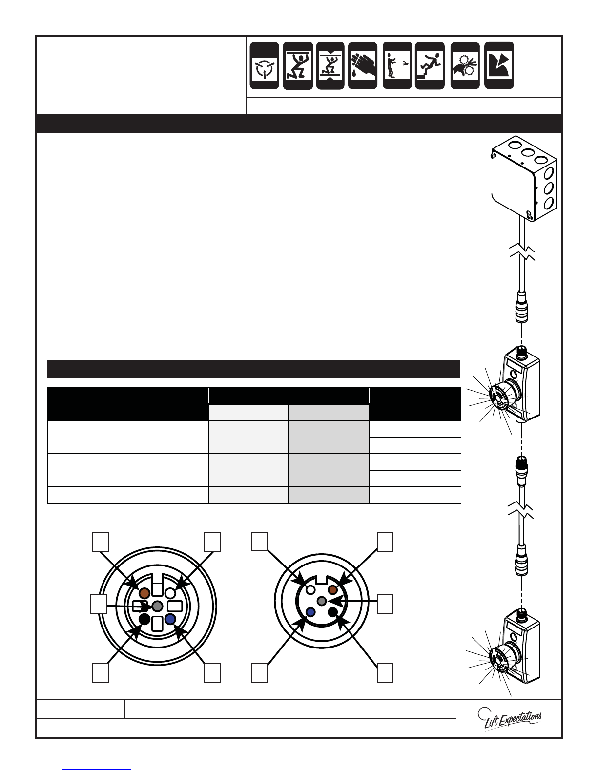
CRUSH
Page 57
STOP PIT SWITCH
INSTALLATION
ANTI-
STATIC
ALERT
CRUSH
HAZARD
HAZARD
CRUSH
CRUSH
HAZARD
HAZARD
CUTTING
CRUSH
HAZARD
HAZARD
ELECTRIC
HAZARD
FALLING
HAZARD
SERIES : All Elevators
WHERE MORE THAN ONE SWITCH IS PROVIDED THEY MUST BE WIRED IN SERIES.
1. Verify power at the controller and disconnect is “OFF”.
2. Using appropriate hardware to mount pit stop switch in the hoistway 18” above
the lowest oor landing and within reach from the lowest oor hoistway door.
Note: If the lowest landing has 2 or more means of access you may need an
additional stop pit switch so a switch can be easily accessed from each access
point.
Per code A17.1 when the pit exceeds 1700mm (67 in.) in depth, an additional
stop pit switch is required and approximately 1200 mm (47 in.) above the pit
oor.
3. Attach the pit stop switch cord and route the cord to the nearest junction box
and wire to the controller box per schematic. the pit stop switch must be wired
to meet N.E.C. and local code.
PINCH
CRUSH
HAZARD
HAZARD
PUNCTURE
HAZARD
NOTE: DO NOT CUT THE CONNECTOR ENDS OFF THE PIT STOP SWITCH CORD.
Controller Terminals
Stop Pit Switch Wires
Wire Numbers
Hydraullic Winding Drum
Brown (Input 1)
1
PS1 PS2
White (Input 2) 2
Black (Output 2)
4
PS2 PS1
Grey (Output 1) 5
Blue -24 -24 3
Male Connector Female Connector
2
2
5
11
5
4 4
PTE10100-G
15 MAY 2018
33
1726 North Ballard Road, Suite 1 - Appleton, WI 54911 - 920.991.9082
Technical Support 855.804.5774 - [email protected]
W
E
Page 58
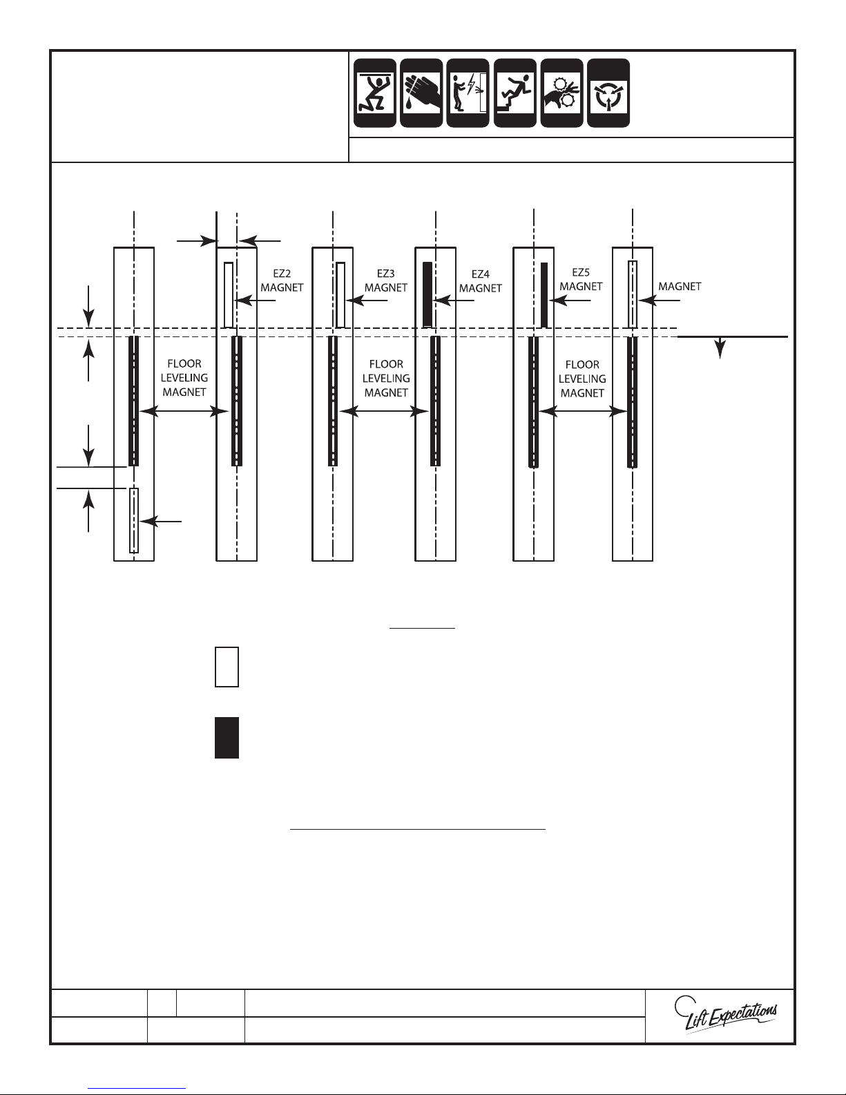
EMI & GAL
Page 58
CRUSH
CUTTING
ELECTRIC
FALLING
PINCH
STATIC
ELECTRICITY
MAGNET PLACEMENT
1/2"
GAP
1-1/2"
C
L
EZ1
MAGNET
C
L
HAZARD
SERIES : 114 , 116
C
L
HAZARD
C
HAZARD
HAZARD
L
C
HAZARD
L
HAZARD
C
L
EZ6
71 3/4"- 74”
Above oor level is
initial setting
adjust as required.
Note:
Measurements are
based o a 7ft car.
Height may vary.
Note: For ne adjustments of oor height, move all the magnets at a landing oor for an adjustment.
LEGEND
WHITE BOXES REPRESENT SOUTH MAGNETS
(South magnets have a yellow stripe on them)
BLACK BOXES REPRESENT NORTH MAGNETS
- Place adhesive side toward steel tape
MAGNETS & THEIR FUNCTIONS
EZ Magnet (4” LONG)
- Powers corresponding EMI
- Resets count to corresponding oor
Floor Leveling Magnet (7” LONG)
- Controls elevator leveling
- Initiates oor count
- Enables PLC to recognize door zone
- Initiates releveling
PTE10025-D
12 JAN 2018
1726 North Ballard Road, Suite 1 - Appleton, WI 54911 - 920.991.9082
Technical Support 855.804.5774 - [email protected]
W
E
Page 59
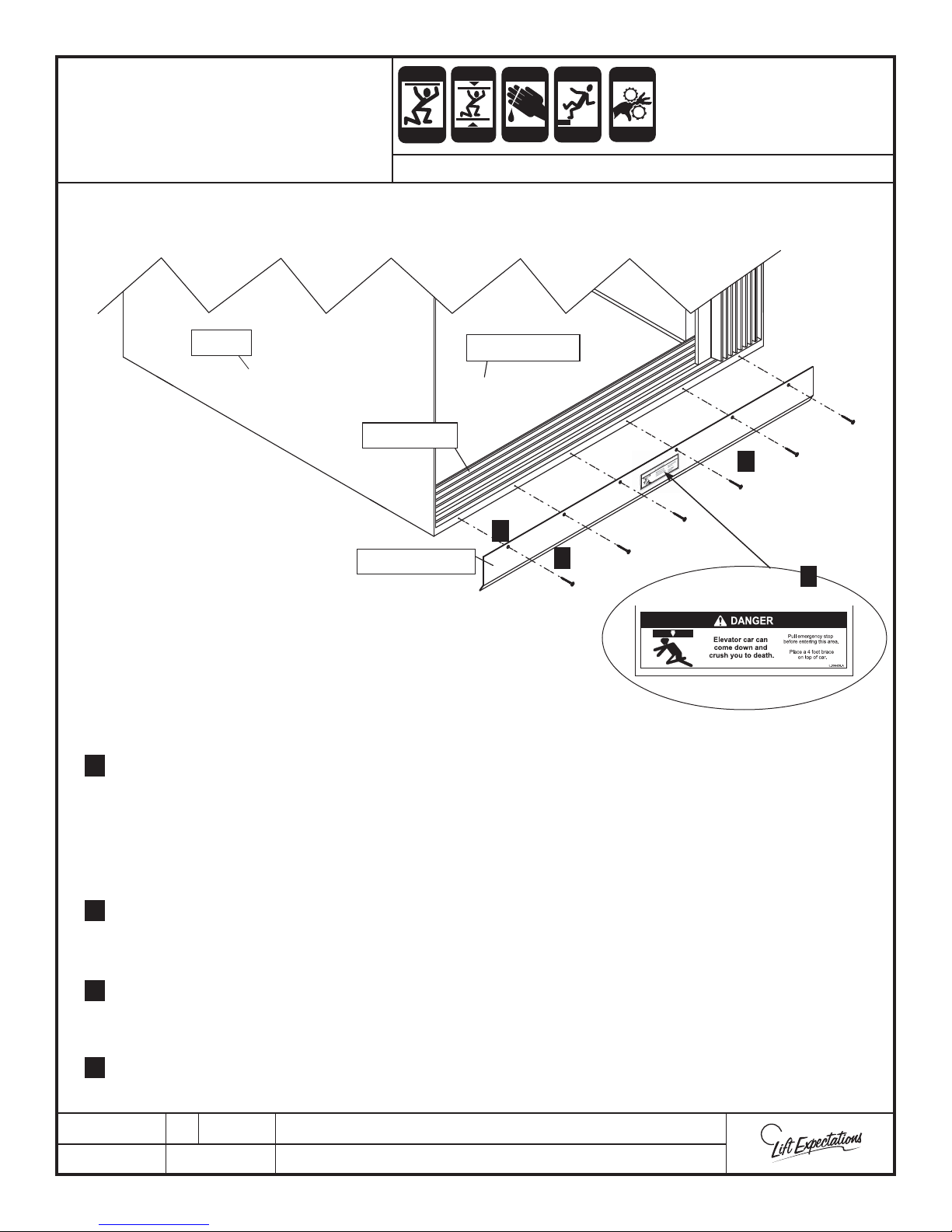
TOE GUARD
Page 59
INSTALLATION
CRUSH
CRUSH
HAZARD
HAZARD
CRUSH
CRUSH
HAZARD
HAZARD
CUTTING
SERIES : All Elevators
CRUSH
HAZARD
HAZARD
FALLING
HAZARD
PINCH
CRUSH
HAZARD
HAZARD
WALL
CAR FLOOR
CAR SILL
1
TOE GUARD
Align toe guard with the bottom of the car sill and one edge of either outside wall with the bend
1.
facing into the hoistway.
4
5
6
2.
Mark all hole locations.
3.
Drill all hole locations previously marked in step 2 with a 3/32” drill bit x 1-1/4” deep pilot hole.
Place toe guard into position established in step 1. Verify both toe guard edges line up with the
4.
outside wall edges, the top of the toe guard lines up with the bottom of the car sill, and the hole
patterns align with the pilot holes drilled.
Fasten toe guard onto car oor with a #6 x 1-1/4” coarse screw per each hole.
5.
Note: Quantity of holes depend on toe guard length.
6.
Place the danger label(s) in the center of opening(s) on provided toe guard(s).
PTM30187-E
20 MAR 2018
1726 North Ballard Road, Suite 1 - Appleton, WI 54911 - 920.991.9082
Technical Support 855.804.5774 - [email protected]
W
E
Page 60
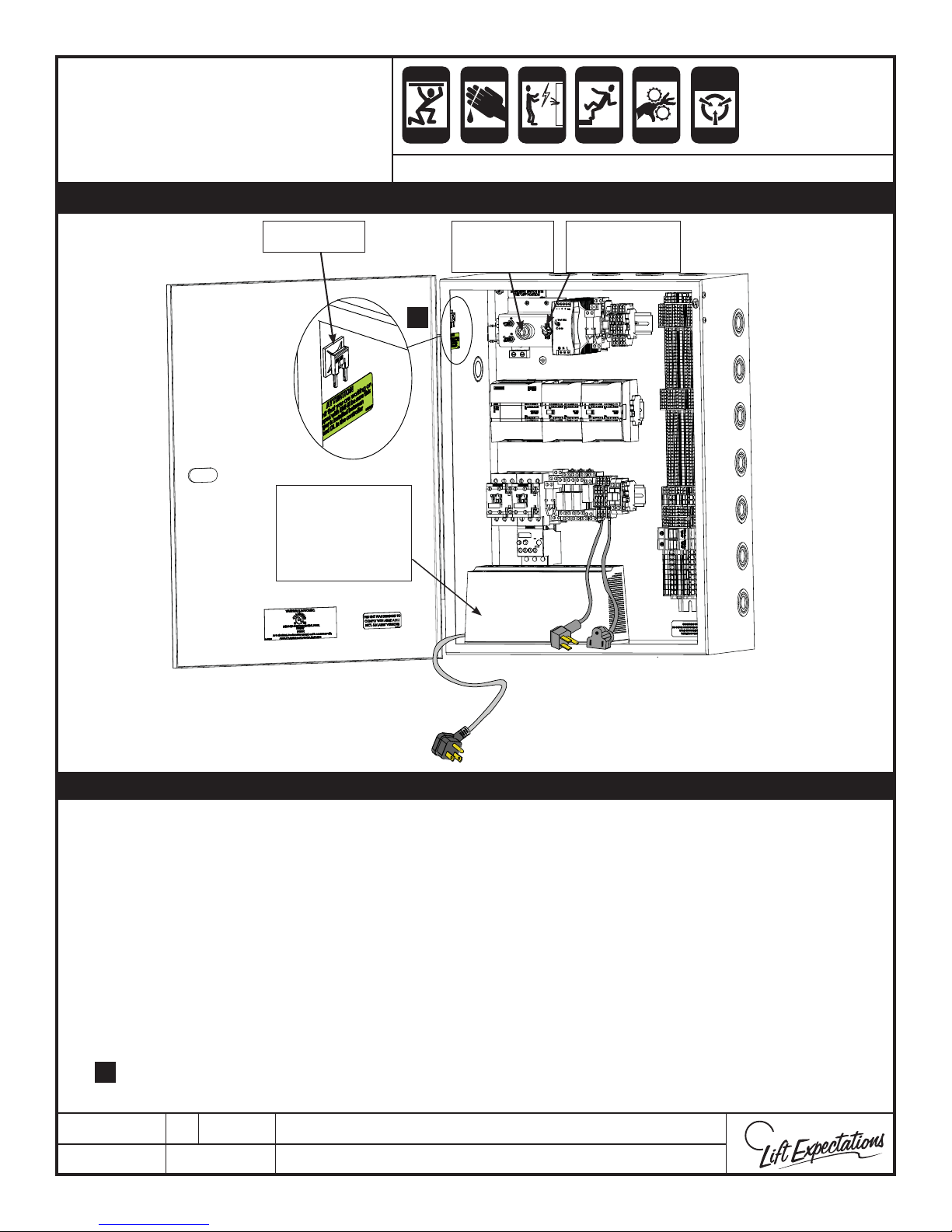
W
E
CRUSH
Page 60
CUTTING
ELECTRIC
FALLING
PINCH
STATIC
ELECTRICITY
AUTOMATIC OPERATION
CRUSH
HAZARD
HAZARD
CRUSH
HAZARD
HAZARD
HAZARD
HAZARD
CRUSH
HAZARD
HAZARD
HAZARD
SERIES : 114, 116
Do not switch to AUTOMATIC OPERATION mode until installation in complete.
Jumper
Uninterruptible
Power
Supply
(UPS)
Pendant
Receptacle
5
On and O
Toggle
Note: The battery back-up is ONLY used for the emergency decent.
Perform the following steps before switching automatic operation:
1. Remove pendant control.
2. Plug UPS backup into the controller.
A) Insert male controller plug into UPS battery backup/surge protection side.
B) Insert male battery backup plug into controller female plug.
3. Turn toggle switch to the “ON” Position.
4. Turn UPS “ON”.
5. If the unit that you are working on is equipped with EMI-
5.
is installed between DC and DL in the controller.
PTE10059-E
14 DEC 2017
III’s be sure the jumper
1726 North Ballard Road, Suite 1 - Appleton, WI 54911 - 920.991.9082
Technical Support 855.804.5774 - [email protected]
Page 61
GMV/OLS
Page 61
CUTTING
ELECTRIC
FALLING
PINCH
STATIC
ELECTRICITY
MICROPROCESSOR
INPUTS & OUTPUTS
Input De nitions
SC = Slack Cable Switch
LPS = Low Pressure Switch
GATE = Gate Switch
ESTP = Emergency Stop Switch
DC = Door Closed Circuit
DL = Door Locked Circuit
DZ = Door Zone Sensor
LD = Level Down Sensor
LU = Level Up Sensor
TF = (CR1) Limit Switch Relay
UP = Up Contactor Input
OVLD = Motor Overload
PF = Power Failure Relay
1-6 F = Floor Call Push Buttons
EZ 1-6 = EZ Magnet Sensors
SW1 = Autogate Programming Switch
Run = Run Contactor Input
SP = Safety Pan Relay
RS = Reset Switch
MAIN PLC FOR GMV/OLS UNITS
CRUSH
HAZARD
HAZARD
SERIES : 114 ,116
HAZARD
HAZARD
CRUSH
HAZARD
HAZARD
HAZARD
Output De nitions
RUN = Run Contactor Output
UP = Up Contactor Output
HSV = High Speed Valve Relay
DV = Down Valve Relay
LR = Cab Light Automatic Timer Relay
SV = Up Low Speed Valve Relay
EMI 1-6 = EMI Outputs
1-6 A = Floor Acknowledgement Lights in
the COP
AG1 = Autogate 1
AG2 = Autogate 2
AG3 = Autogate 3
DF = Door Fault
Note: Highlighted
Inputs MUST be ON
when the elevator
is stationary and in
automatic mode!
Input (I)
Indication
Outputs
(Q)
Indication
Input (I) 0.0 0.1 0.2 0.3 0.4 0.5 0.6 0.7
IndicaƟ on
Output (Q)
IndicaƟ on
Gate Estop DC DL LPS PS TF OVLD
0.0 0.1 0.2 0.3 0.4 0.5
Run/In Use
Up HSV Down SV LR
EXPANSION MODULE FOR GMV/OLS UNITS
10.0
10.1
10.2
10.3
6F
10.3
10.4
SP
10.4
8.0
SC
8.0
EMI1
8.1
UP
8.1
EMI2
8.2
RUN
8.2
EMI3
8.3
PF
8.3
EMI4
8.4
8.4
EMI5
8.5
DZ
8.5
EMI6
8.6
LU
8.6
DF
8.7
LD
8.7
9.0
EZ1
9.0
1A
9.1
EZ2
9.1
2A
9.2
EZ3
9.2
3A
9.3
EZ4
9.3
4A
9.4
EZ5
9.4
5A
9.5
EZ6
9.5
6A
9.6
1F
9.6
9.7
2F
9.7
3F
10.0
AG1
4F
10.1
AG2
5F
10.2
AG3
10.5
RS
10.5
10.6
SW1
10.6
10.7
PTE10010-I
23 FEB 2018
1726 North Ballard Road, Suite 1 - Appleton, WI 54911 - 920.991.9082
Technical Support 855.804.5774 - [email protected]
W
E
Page 62
CRUSH
Page 62
PROGRAMS & POT
ANTI-
STATIC
ALERT
CRUSH
HAZARD
HAZARD
CRUSH
CRUSH
HAZARD
HAZARD
CUTTING
CRUSH
HAZARD
HAZARD
ELECTRIC
HAZARD
FALLING
HAZARD
PINCH
CRUSH
HAZARD
HAZARD
SETTINGS
SERIES : 114 , 116
PROGRAM FEATURES
Field Programmable Floor Homing
Floor homing runs the elevator car to a speci c oor after 30 minutes of idle time.
Enabling Instructions:
• Call unit to lowest landing. (tape reader must be on EZ1 magnet)
• Open gate and pull Emergency-Stop button. (ESTP input must be disengaged)
• While in the car, push and hold COP buttons 1 & 2 (simultaneously) until both illuminate,
then release.
• Immediately push and release the desired homing oor button while 1 & 2 are
illuminated. (they will time out in 6 seconds)
• Selection will ash multiple times to acknowledge program accepted.
(Wait a few seconds)
Disabling Instructions
• To disable the homing feature, push and hold buttons 1 & 2 (simultaneously) until they light.
Continue to hold 1 & 2 until the lights go out and release.
Hydraulic Exercise Programming
The hydraulic exercise program runs the elevator every 2 weeks if the elevator is idle. This
program is turned ‘ON” when the elevator is shipped.
Disabling/Enabling the Exercise Program Instructions:
• Call the unit to the second stop. (tape reader must be on EZ2 magnet)
• Open gate and pull the Emergency-Stop button. (ESTP input must
be disengaged)
• While in the car, push and hold the COP buttons 1 & 2 (simultaneously)
until they both illuminate.
• While the buttons 1 & 2 are illuminated (they will time out in 3 seconds)
push 2 to enable the exercise program, or 1 to disable the exercise
program.
PTE10115-H
12 FEB 2018
1726 North Ballard Road, Suite 1 - Appleton, WI 54911 - 920.991.9082
Technical Support 855.804.5774 - [email protected]
W
E
Page 63
CRUSH
Page 63
PROGRAMS & POT
SETTINGS
ANTI-
STATIC
CRUSH
HAZARD
ALERT
SERIES : 114 , 116
HAZARD
CRUSH
CRUSH
HAZARD
HAZARD
CUTTING
CRUSH
HAZARD
HAZARD
ELECTRIC
HAZARD
PROGRAM FEATURES CONTINUED
Field Programmed Timer for EMI Time-out Applications
Adjustment Instructions:
• Pot 1 adjusts the timer for the EMIs, turn the pot (rheostat) to t the application:
• Fully counterclockwise is 10 seconds, fully clockwise is 120 seconds.
Field Programmed Car Light Time-out
Adjustment Instructions:
• Pot 2 adjusts the timer for the car lights, turn the pot
(rheostat) to t the application:
• Fully counterclockwise is 5 minutes, fully clockwise is 30 minutes.
EMI and Car light
timeout features will
not implement any
changes until a landing
door (Door Circuit) has
been cycled; this may
be any landing door.
Pot 1
(EMI)
FALLING
HAZARD
PINCH
CRUSH
HAZARD
HAZARD
EMI TIMEOUT TIMER
(Pot 1)
10 SEC
CAR LIGHT TIMER
(Pot 2)
120 SEC
Pot 2
(Light)
5 MIN
Gate Cycle Safety Feature
• To ensure the gate contacts are not welded. At a landing; the door close and gate
contacts must open at least once. If just the gate contacts open the unit will be able to run
just 4 times.
• To return to normal operation open and close both the gate and the hoistway door. Then the
elevator will respond to calls.
• To reset elevator program, the gate switch contact must be broken and recontacted to
resume proper function.
PTE10115-H
12 FEB 2018
1726 North Ballard Road, Suite 1 - Appleton, WI 54911 - 920.991.9082
Technical Support 855.804.5774 - [email protected]
W
30 MIN
E
Page 64
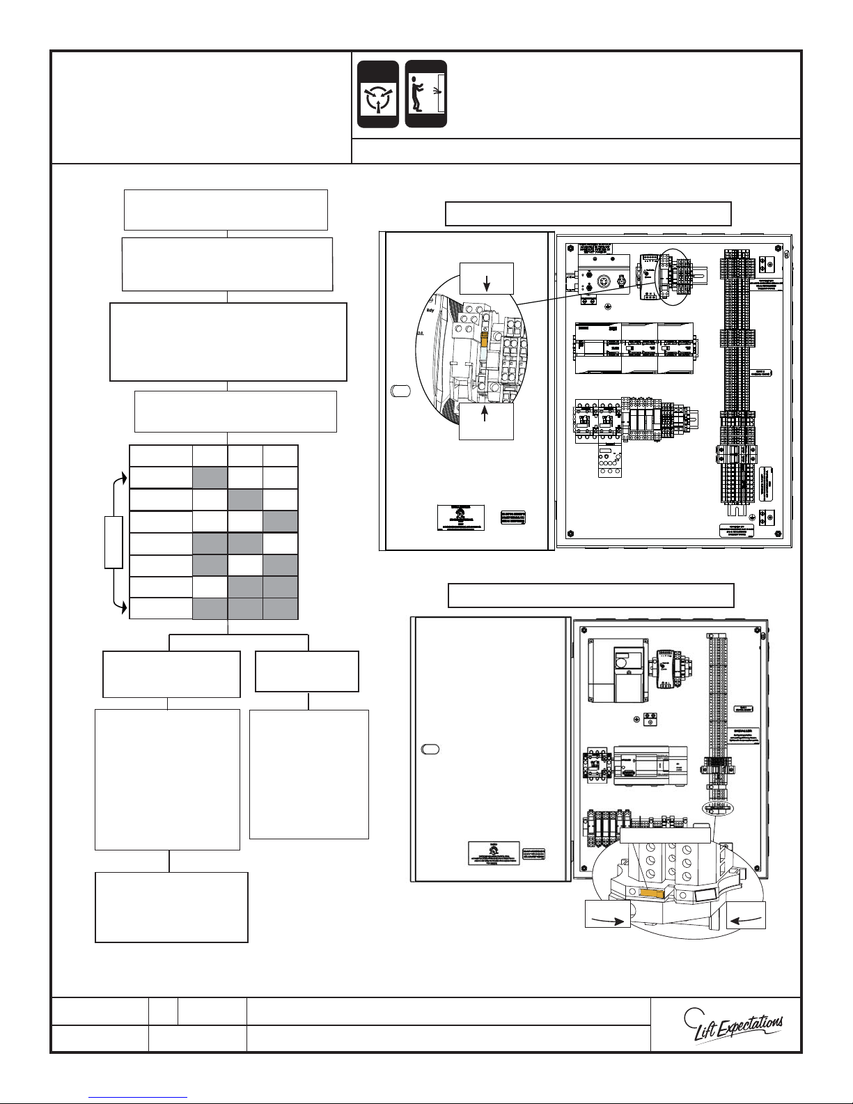
ANTI-
Page 64
STATIC
ELECTRIC
AUTO GATE PROGRAM
Auto Gate Program
Move Elevator to Desired Floor.
NOTE: Elevator must be on EZ
magnet/input.
Flip SW1 to "CLOSED" POSITION.
(located inside controller)
NOTE:
Unit will not accept oor calls with SW1 in
closed position.
Press the Corresponding
Call Floor Button.
AG2
PRESS 7x’s
AG1
PRESS 0x’s
PRESS 1x’s
PRESS 2x’s
PRESS 3x’s
PRESS 4x’s
PRESS 5x’s
PRESS 6x’s
AG3
indicates AG
programmed to
ALERT
HAZARD
SERIES : 008, 021, 022, 114, 115, 116, 118, 210
HYDRAULIC CONTROLLER SHOWN
OPEN
SWI
Closed
Gray square
open.
SW1 Switch shown
in closed position
WINDING DRUM CONTROLLER SHOWN
All Desired Gates
Open Correctly.
Flip SW1 to
"OPEN" POSITION
TO END this oor's
programming.
NOTE:
Unit will not accept oor
calls with SW1 in
closed position.
Move Elevator
to Any Other Desired
Floor and Repeat.
PTE10194-D
13 MAR 2018
Wrong Gates
Opens.
Press the
Corresponding
Call Floor Button.
(with all doors &
gates closed)
Reference chart for
number of times to
push the button.
1726 North Ballard Road, Suite 1 - Appleton, WI 54911 - 920.991.9082
Technical Support 855.804.5774 - [email protected]
SWITCH POSITION
SWITCH POSITION
CLOSED
CLOSED
SW1
OPEN
SW1 Switch shown
in closed position
W
E
Page 65
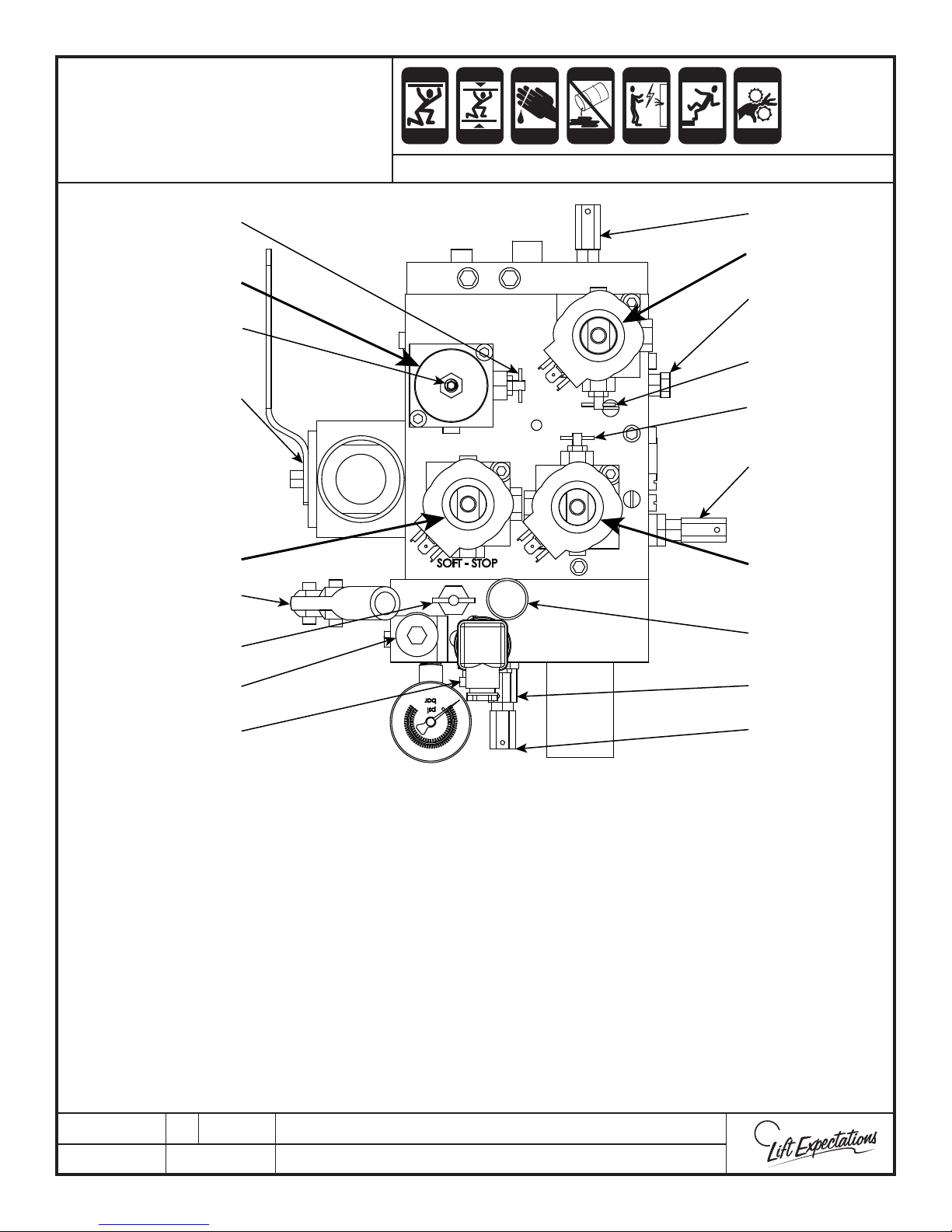
CRUSH
Page 65
CRUSH
CUTTING
ECO-SYSTEM
ELECTRIC
FALLING
PINCH
VALVE ADJUSTMENTS
5
VRFP
9
CHECK VALVE
CRUSH
HAZARD
HAZARD
SERIES : 114, 116
CRUSH
HAZARD
HAZARD
CRUSH
HAZARD
HAZARD
HAZARD
HAZARD
HAZARD
CRUSH
HAZARD
HAZARD
8
VML
2
3
4
1
VMD
HAND PUMP
6
12
11
1) Main Pressure Relief Valve Adjustment
2) Leveling Speed Adjustment
3) Speed Transition Adjustment
4) Up Acceleration Adjustment
5) Down Speed Override
6) Pressure Gauge Shuto Screw
7) Manual Lowering Min. Pressure Adjustment
8) Pressure Balance
9) Down Speed Adjustment
10) Hand Pump Pressure Relief Valve Adjustment
11) Hand Pump Air Bleeder
12) Inspection Gauge Fitting
VP
MANUAL
LOWERING
7
10
VP) Pressure Valve
VMD) Down Solenoid Valve
VML) Full Speed Solenoid Valve
VRFP) Auxiliary Down Speed Control Valve
TROUBLESHOOTING TIP:
When energized, the coil stem becomes magnetized. Con rm
this by placing a steel tool such as a wrench or screwdriver on
the stem.
VMD: Energized in Down Direction
VML: Energized in Both Up and Down Directions
VP: Energized in Up Direction
PTM30141-D
13 MAR 2018
1726 North Ballard Road, Suite 1 - Appleton, WI 54911 - 920.991.9082
Technical Support 855.804.5774 - [email protected]
W
E
Page 66
CRUSH
Page 66
CRUSH
CUTTING
ECO-SYSTEM
ELECTRIC
FALLING
PINCH
VALVE ADJUSTMENTS
CRUSH
HAZARD
HAZARD
SERIES : 114, 116
CRUSH
HAZARD
HAZARD
CRUSH
HAZARD
HAZARD
HAZARD
HAZARD
HAZARD
CRUSH
HAZARD
HAZARD
ADJUST RUN/LEVEL SPEED
1. Adjust leveling speed (#2) until it is approximately 6-8 feet per minute (fpm).
A. “Out” is faster.
B. Adjustment screw should be almost completely turned in when properly set, begin from
this position and adjust accordingly.
2. Adjust down speed (#9) until it matches the up speed.
3. Set high speed in both up and down directions by adjusting pressure balance (#8) until speed is
40 fpm.
A. “Out” is faster.
4. Recheck that up/down speed match and that leveling speed is within acceptable parameters,
read just if necessary.
A. If readjustments were required, recheck high speed and adjust if necessary.
B. Repeat these steps as necessary until all speeds are within acceptable parameters.
ADJUST PRESSURE RELIEF VALVE
1. Load elevator to maximum rated capacity and run the unit to ensure working pressure is less
than 740 psi.
A. If the pressure while under full load exceeds 740 psi contact technical support before
proceeding any further.
B. Take note of the pressure during this step, this is the working pressure of this particular
elevator.
*All elevators will have a slightly di erent working pressure due to head losses
resulting from piping con gurations and accuracy of jack plumbness.
2. Close shuto valve.
3. Run unit by placing a call.
4. Adjust pressure relief (#1) until pressure is less than 150% of working pressure found when run
under full load.
A. Waupaca Elevator recommends that the valve not be adjusted to below 125% of working
pressure to ensure proper operation of the elevator.
5. Open shuto valve.
TEST EMERGENCY MANUAL LOWERING
1. Depress emergency manual lowering button and ensure the elevator lowers.
2. If the elevator does not lower, contact technical support before proceeding any further.
TEST MANUAL PUMP
1. Remove handle from retaining clips and place inside manual pump.
2. Operate manual pump and ensure that the elevator raises.
A. Elevator will raise approximately 1/8” per pump.
3. If elevator does not raise, contact technical support before proceeding any further.
PTM30141-D
13 MAR 2018
1726 North Ballard Road, Suite 1 - Appleton, WI 54911 - 920.991.9082
Technical Support 855.804.5774 - [email protected]
W
E
Page 67
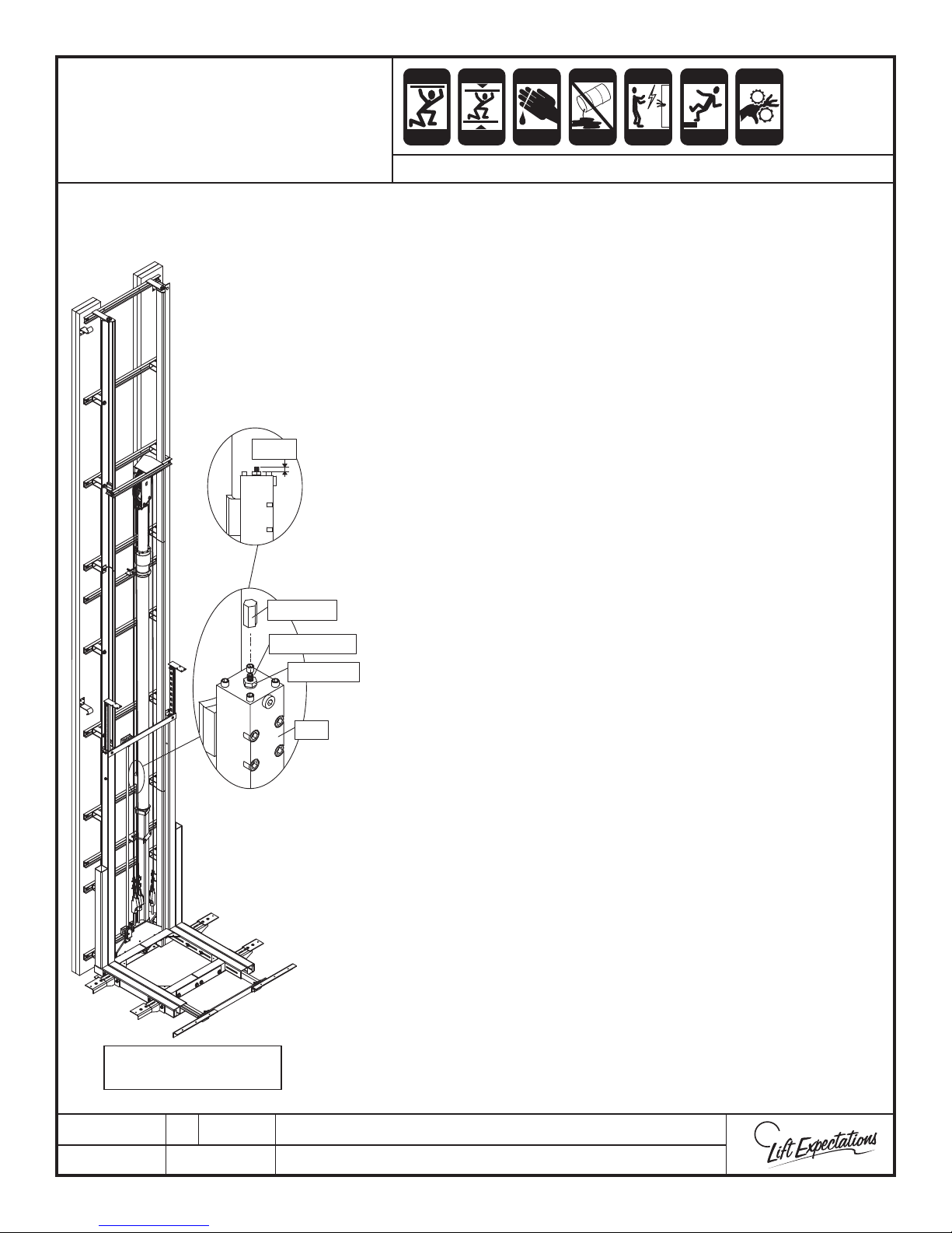
CRUSH
Page 67
CRUSH
CUTTING
ECO-SYSTEM
ELECTRIC
FALLING
PINCH
VALVE ADJUSTMENTS
5/16"
CAP NUT
SET SCREW
JAM NUT
PRV
CRUSH
HAZARD
HAZARD
CRUSH
HAZARD
HAZARD
CRUSH
HAZARD
HAZARD
HAZARD
HAZARD
HAZARD
CRUSH
HAZARD
HAZARD
SERIES : 114 , 116
ADJUST PIPE RUPTURE VALVE
1. Load elevator to maximum rated capacity and raise to the
top oor by either pendant or placing a call.
2. Remove cap nut on pipe rupture valve and loosen the jam
nut.
3. Turn the set screw in (clockwise) until the valve is fully
closed.
4. Lower the elevator with the pendant, the valve will set
A. If the valve does not set, contact technical support
before proceeding any further.
5. Turn set screw out (counter-clockwise) until 5/16” is
exposed over the top of the jam nut, then lock with jam
nut.
6. Run elevator down and ensure the valve does not set
during normal operation.
A. If the valve sets during normal operation , adjust the
set screw as necessary.
7. Thread the cap nut back over the set screw and tighten
against the jam nut.
TEST THE PIPE RUPTURE VALVE
*Ensure oil is at room temperature before testing the valve.
1. Turn Down Speed Override (#5) clockwise until fully closed.
Lower elevator to actuate pipe rupture valve.
A. Ensure valve sets at a speed in the range of 110-140%
of maximum rated speed (40 feet per second) per
ASME-A17.1
B. If necessary, adjust pipe rupture valve until
appropriate setting speeds are met.
2. Once valve is actuated (elevator will completely stop) turn
#5 counter-clockwise until completely open.
3. Raise elevator to reset pipe rupture valve.
4. Seal valve with tamper evident seal.
SERIES 116 SHOWN FOR
ILLUSTRATIVE PURPOSES
PTM30141-D
13 MAR 2018
1726 North Ballard Road, Suite 1 - Appleton, WI 54911 - 920.991.9082
Technical Support 855.804.5774 - [email protected]
W
E
Page 68
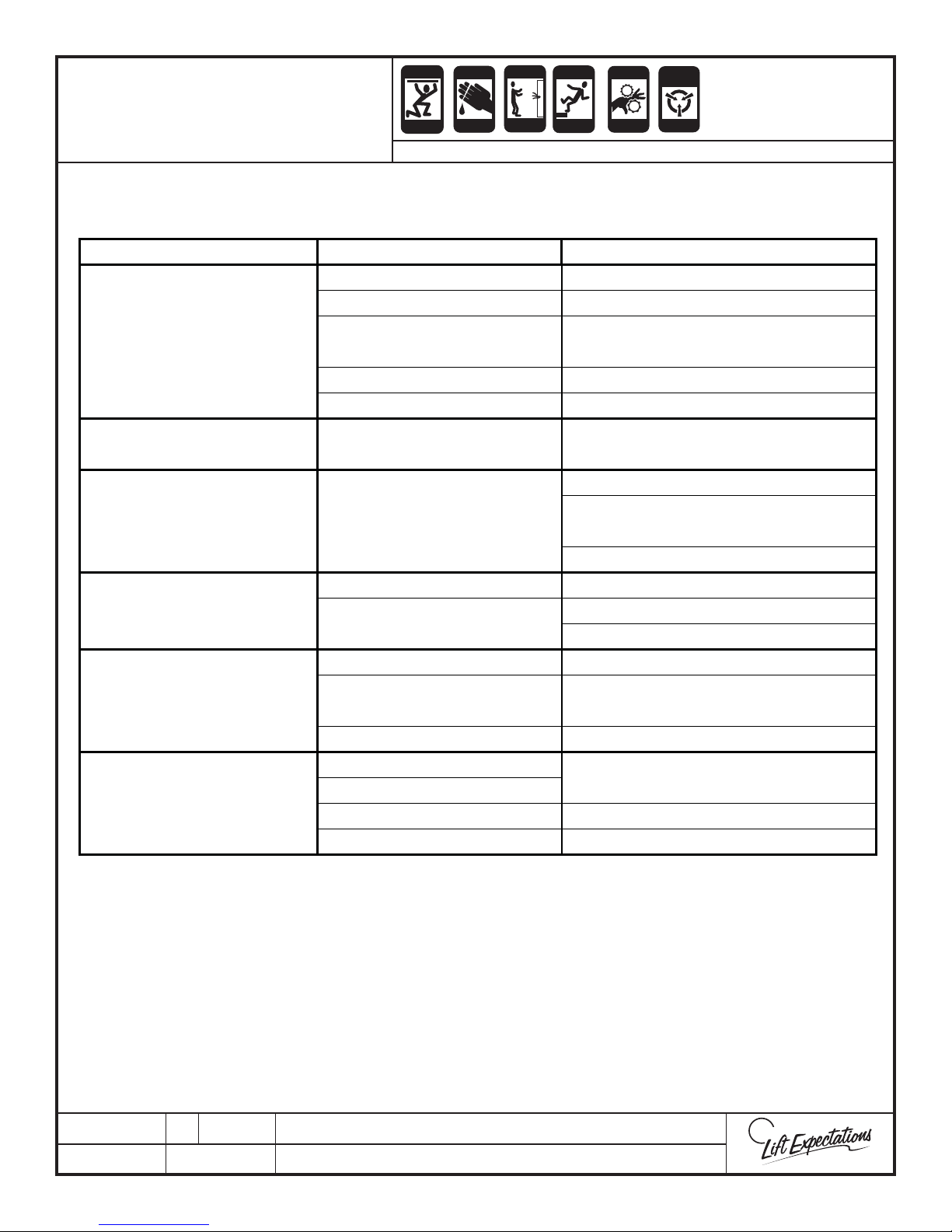
TROUBLESHOOTING
Page 68
Fault: Problem Cause: Action:
CRUSH
CRUSH
HAZARD
HAZARD
CUTTING
HAZARD
CRUSH
HAZARD
ELECTRIC
HAZARD
FALLING
HAZARD
PINCH
CRUSH
HAZARD
HAZARD
STATIC
ELECTRICITY
HAZARD
SERIES : 114 - 116
PLC count is incorrect Check DZ & EZ magnets and sensors
Pressure relief set too low Adjust pressure relief valve
Elevator Travels in Slow Speed
Only
Excessive tension between mov-
ing parts
HSV Check that VML coil is magnetized
High Speed Circuit Check that HSV circuit is actuating
Misses Destination Floor PLC not seeing DZ input
Elevator Stops Short of Top
Floor and Returns to 1st Floor
with Car Lights Blinking
Low oil time out fault
90 seconds
Up contactor not pulling in Check up output on PLC and UP contactor
Elevator Travels Down Only
No incoming power
Misplaced magnet Check Magnet placement
Elevator Relevels Excessively
Leak in hydraulic system
Leveling speed adjustment Adjust leveling speed
EZ input missing
Interlock Will Not Release
When Car is at Floor
EMI output missing
Faulty EMI Check interlock and related wiring
Interlock missing alignment Correct alignment isse
Check for binding in the rail, sling or jack
Check DZ magnets, tape reader, interface
board, and related wiring
Check oil level and oil temperature
Check for leak in pump assembly, pump to
jack plumbing.
Check HSV
Check up output on PLC and UP contactor
Check for fuse F13A and PF relay
Check for internal or external leaks in valve,
hose and/or jack
Check magnet placement, tape reader and
interface board
PTE10157-D
15 FEB 2018
1726 North Ballard Road, Suite 1 - Appleton, WI 54911 - 920.991.9082
Technical Support 855.804.5774 - [email protected]
W
E
Page 69
TROUBLESHOOTING
Page 69
Fault: Problem Cause: Action:
CRUSH
CRUSH
HAZARD
HAZARD
CUTTING
HAZARD
CRUSH
HAZARD
ELECTRIC
HAZARD
FALLING
HAZARD
PINCH
CRUSH
HAZARD
HAZARD
STATIC
ELECTRICITY
HAZARD
SERIES : 114 - 116
Open safety Check for required inputs
Elevator Will Not Accept a
Call
Does Not Slow Down
Travels Past Floor then
Relevels
Will Not Travel Down
Elevator stops just outside
of the door zone while leav-
ing the oor landing
Door must be cycled after four calls or the
Door Lock cycle count
system will stop functioning
Open gate and open door
PLC count is incorrect Check for DZ input when elevator is running
Improper magnet placement Check magnet placement
Leveling speed is too fast
Adjust leveling speed
HSV Relay is welded
Check pipe rupture valve and adjust
Pipe rupture valve is out of
adjustment
Check pressure gage to determine if pipe
rupture is working
(EMI-III) Missing jumper from
DC to DL
Add the 2 pole jumper in DC and DL in
controller
Faulty EMI
Replace or adjust EMI
(EMI-IV) Door Locked Circuit
Open
Verify wiring and alignment of EMI
If the unit can run with the
door open with an EMI-IV
and GAL interlocks
PTE10157-D
15 FEB 2018
Verify the door lock and door
Verify EMI-IV interlock wiring
closed aren’t tied together
Remove the 2 pole jumper from DC and DL
in the controller
1726 North Ballard Road, Suite 1 - Appleton, WI 54911 - 920.991.9082
Technical Support 855.804.5774 - [email protected]
W
E
Page 70
TROUBLESHOOTING PLC
Page 70
INPUTS / OUTPUTS
ELECTRIC
HAZARD
SERIES : 114 , 116
PINCH
CRUSH
HAZARD
HAZARD
STATIC
ELECTRICITY
HAZARD
Input Description
Action
I0.0 Emergency stop switch Must be on for unit to operate
I0.1 Gate Switch
I0.2 Door Closed Switches
I0.3 Door Locked Switches
I0.4 Low Pressure Switch
I0.5 Pit Switch
I0.6 Contacts of CR1
CR1 pulls in when the top nal limit switch is made.
Must be on for unit to operate
Must be on for unit to operate
Must be on for unit to operate
Must be on for unit to operate
Must be on for unit to operate
Must be on for unit to operate.
I0.7 Overload
I8.0 Slack Cable
I8.1 Up contactor
I8.2 Run Contactor
I8.3 Power failure relay
I8.4
I8.5 Door zone sensor
I8.6 Level up sensor
I8.7 Level down sensor
I9.0 EZ 1 Sensor
Initiates the slow down when coming to a oor
Lights when at the rst oor, triggers EMI1 output
Must be on for unit to operate
Must be on for unit to operate
Tells the PLC that the unit is running up
Tells the PLC its running
Must be on to operate in up direction
Not Used
Maintains the cars position at the oor
Maintains the cars position at the oor
I9.1 EZ 2 Sensor Lights when at the second oor, triggers EMI2 output
PTE10146-F
30 MAR 2018
I9.2 EZ 3 Sensor
I9.3 EZ 4 Sensor
I9.4 EZ 5 Sensor
I9.5 EZ 6 Sensor
I9.6 First oor push button
Lights when at the third oor, triggers EMI3 output
Lights when at the fourth oor, triggers EMI4 output
Lights when at the fth oor, triggers EMI5 output
Lights when at the sixth oor, triggers EMI6 output
Lights when rst oor call is made
I9.7 Second oor push button Lights when second oor call is made
I10.0 Third oor push button
I10.1 Fourth oor push button
I10.2 Fifth oor push button
I10.3 Sixth oor push button
I10.4 Safety Pan (SCR)
I10.5 Reset switch
I10.6 SW1
1726 North Ballard Road, Suite 1 - Appleton, WI 54911 - 920.991.9082
Technical Support 855.804.5774 - [email protected]
Lights when third oor call is made
Lights when fourth oor call is made
Lights when fth oor call is made
Lights when sixth oor call is made
Must be on for unit to operate
Resets Door Fault
Must be on to program auto gates
W
E
Page 71
ELECTRIC
Page 71
PINCH
STATIC
ELECTRICITY
TROUBLESHOOTING PLC
CRUSH
INPUTS / OUTPUTS
HAZARD
SERIES : 114 ,116
Output Description Action
Q0.0 In use lights and run contactor Lights when the car is running
Q0.1 UP Lights when the car is running in the up direction
Q0.2 HSV Lights when the car is running in full speed
Q0.3 DV Lights when the car is running in the down direction
Q0.4 SV Lights when the car is running up
Q0.5
Light Relay
Q8.0 EMI 1
Q8.1 EMI 2
Q8.2 EMI 3
Q8.3 EMI 4
Q8.4 EMI 5
Q8.5 EMI 6
Q8.6 DF Indicates Door Fault Condition
Q8.7 SCR Reset On First Scan Resets SCR
HAZARD
HAZARD
HAZARD
Lights when car is stopped at a oor and the door is
closed, stays lit for 5 min - 30 min
Lights when the car is at the rst oor and EZ 1 input is
Lights when the car is at the second oor and EZ 2
Lights when the car is at the third oor and EZ 3 input
Lights when the car is at the fourth oor and EZ 4 input
Lights when the car is at the fth oor and EZ 5 input is
Lights when the car is at the sixth oor and EZ 6 input
on
input is on
is on
is on
on
is on
Q9.0 First oor acknowledge light Lights when a rst oor call is engaged
Q9.1 Second oor acknowledge light Lights when a second oor call is engaged
Q9.2 Third oor acknowledge light Lights when a third oor call is engaged
Q9.3 Fourth oor acknowledge light Lights when a fourth oor call is engaged
Q9.4 Fifth oor acknowledge light Lights when a fth oor call is engaged
Q9.5 Sixth oor acknowledge light Lights when the sixth oor is engaged
Q9.6 Not Used
Q9.7 Not Used
Q10.0 AG1
Q10.1 AG2
Q10.2 AG3
PTE10146-F
30 MAR 2018
Lights when car is at a oor where AG1 is programmed
to open
Lights when car is at a oor where AG2 is programmed
to open
Lights when car is at a oor where AG3 is programmed
to open
1726 North Ballard Road, Suite 1 - Appleton, WI 54911 - 920.991.9082
Technical Support 855.804.5774 - [email protected]
W
E
Page 72
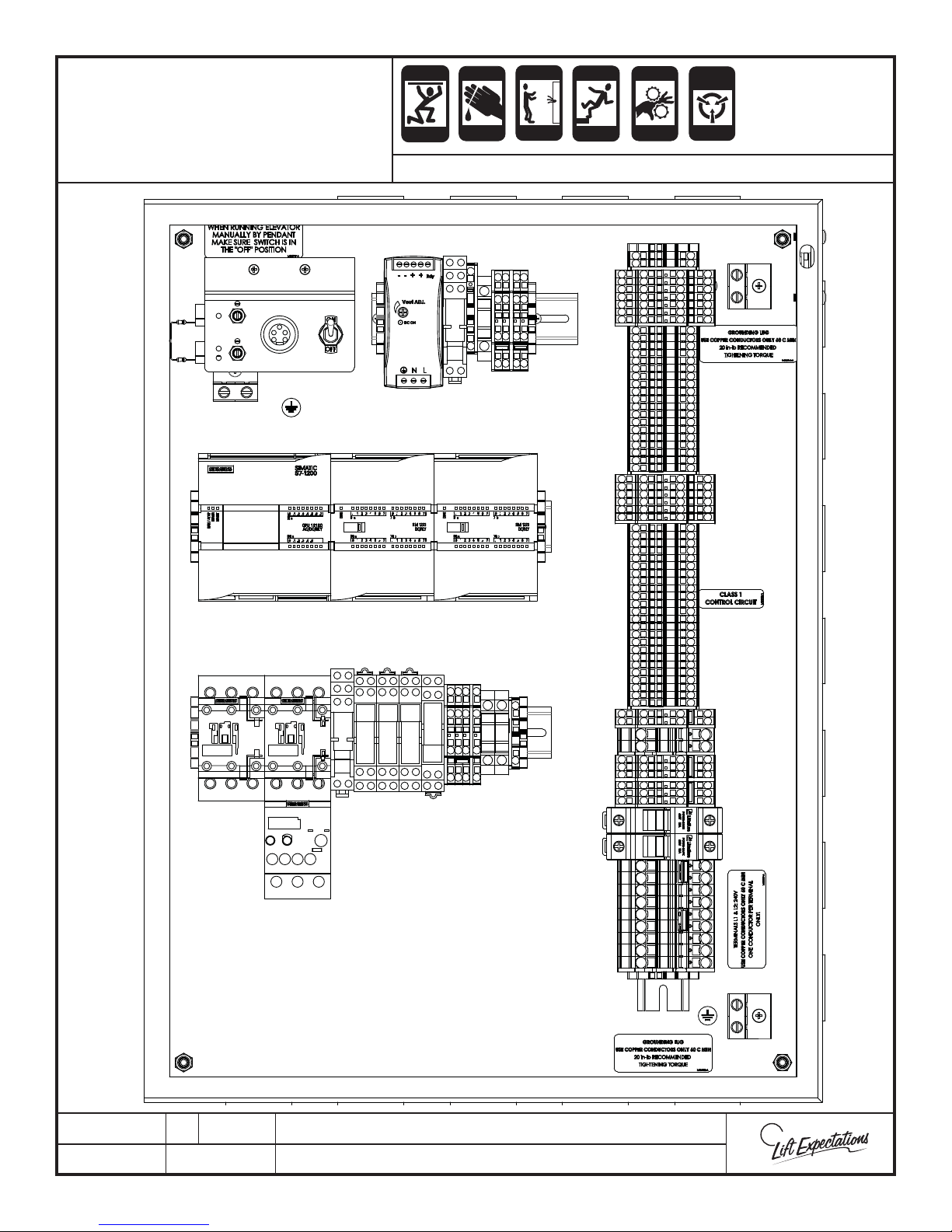
EZ3
TROUBLESHOOTING
Page 72
CONTROLLER LAYOUT
PLC
SCR
RUN
UP
SCR HSV DV SV PF
OVLD
CRUSH
HAZARD
SERIES : 114 , 116
24VDC
Power
Supply
EXP
MODULE
HSV
DV
CRUSH
HAZARD
SV
CUTTING
CRUSH
HAZARD
HAZARD
ELECTRIC
HAZARD
CR1
F32A
SW1
+24
+24
-24
-24
CR1
EXP
MODULE
PF
F13A
F24A
GRD
+24
+24
FALLING
HAZARD
Phone
Phone
1F
2F
3F
4F
5F
6F
FC
DZ
LU
LD
SP1
SP2
SC
ESTP
GATE
LITE
AG1
AG2
AG3
1A
2A
3A
4A
5A
6A
AC
EZ1
EZ2
EZ4
EZ5
EZ6
PS1
PS2
TF1
TF2
DC
DC/DL
DL
IU1
IU2
RS1
RS2
EMI1
EMI2
EMI3
EMI4
EMI5
EMI6
EC
DF
LPS1
LPS2
DV
HSV
SV
VC
VC
T1
T2
+24
+24
+24
-24
-24
-24
NEUT
NEUT
NEUT
LT
AUX
AUX
NEUT
NEUT
COM
L1
L2
PINCH
CRUSH
HAZARD
HAZARD
STATIC
ELECTRICITY
HAZARD
110L
110A
PTE30187-A
30 MAR 2018
1726 North Ballard Road, Suite 1 - Appleton, WI 54911 - 920.991.9082
Technical Support 855.804.5774 - [email protected]
W
E
Page 73
Serial #
Page 73
SEMI-ANNUAL GENERAL
Owner
Date Installed Floors Travel Speed Motor Voltage
MAINTENANCE CHART
SERIES : 114, 116
ALWAYS DE-ENERGIZE ELECTRICAL CIRCUITS and follow proper tag out procedures during servicing or maintenance of elevator.
USE ONE COLUMN PER VISI T
1 2 3 4 5 6 7 8 9 10
1 2 3 4 5 6 7 8 9 10
1 2 3 4 5 6 7 8 9 10
ON EVERY VISIT CHECK THE FOLLOWING:
OV E RALL INSP ECT IO N
See customer and correct all complaints
Inspect machine space equipment and clean w hen necessary
Ride car, checking for unusual noise or operation
Check condition of car top, pit equipment, clean when necessary
Check for burned out lights and replace
PUMP UNIT
Maintain oil tank at proper level [AW-32]
Check for ex cessive leaks around valve and pipe connections
Check all electrical connections
Test run checking for ex cessive noise and vibration
JACK
Check plunger for signs of rust and scratches
Check packing gland for leakage
Check pipe rupture valve for leakage
Check wear and leakage of hose/pipe
Check pit bucket and empty
Bleed Jack
Date Technician
1 2 3 4 5 6 7 8 9 10
1 2 3 4 5 6 7 8 9 10
1 2 3 4 5 6 7 8 9 10
1 2 3 4 5 6 7 8 9 10
CONTROLLER
Check contacts for ex cessive burning and clean
Check and test battery device
Check fuses, holders, and replace if necessary
GAT E
Check gate operation
Clean and lubricate rollers
Check and clean gate operator & switches
CAR
Check alarm bell system
Check emergency stop sw itch
Check adjustment of car guide blocks
Check roller wheels/guides
Check operation and movement of slack cable/broken rope safety
Check COP lights
Check contacts and switches in car operating panel
Check telephone is functioning
HOISTWAY
Check rail bracket fasteners are secure and lubricate rail
Check hall button contacts, clean if required
Check and clean main guide rails and guide blocks
Check wear and insulation on traveling cable
Check junction box
Check and clean interlocks
Inspect and lubricate ropes ( Nyrosten Ropeoil Compound)
Check ropes for equal tension
Check slack rope sw itch and pit sw itch
Final Limits and Pit Switch
Check Car Top Stop Switch
Test Emergency Light
Maintenance Messages
LUBRICATION
RECOMMENDATIONS:
- Use spray lubricant that
meets and/or exceeds MIL-C81309D & MIL-C-16173D.
- Approved elevator rope
lubricant should be applied
sparingly to penetrate but not
drip from the rope.
PTS70057-C
13 MAR 2018
1726 North Ballard Road, Suite 1 - Appleton, WI 54911 - 920.991.9082
Technical Support 855.804.5774 - [email protected]
W
E
Page 74
SEMIANNUAL
Page 74
MAINTENANCE MESSAGES
SERIES : 114, 116
_______________________________________________________________________________________
_______________________________________________________________________________________
_______________________________________________________________________________________
_______________________________________________________________________________________
_______________________________________________________________________________________
_______________________________________________________________________________________
_______________________________________________________________________________________
_______________________________________________________________________________________
_______________________________________________________________________________________
_______________________________________________________________________________________
_______________________________________________________________________________________
_______________________________________________________________________________________
_______________________________________________________________________________________
_______________________________________________________________________________________
_______________________________________________________________________________________
_______________________________________________________________________________________
_______________________________________________________________________________________
_______________________________________________________________________________________
_______________________________________________________________________________________
_______________________________________________________________________________________
_______________________________________________________________________________________
_______________________________________________________________________________________
_______________________________________________________________________________________
_______________________________________________________________________________________
_______________________________________________________________________________________
_______________________________________________________________________________________
_______________________________________________________________________________________
_______________________________________________________________________________________
_______________________________________________________________________________________
PTS70057-C
13 MAR 2018
1726 North Ballard Road, Suite 1 - Appleton, WI 54911 - 920.991.9082
Technical Support 855.804.5774 - [email protected]
W
E
Page 75
ELEVATOR RELEASE
Page 75
CHECKLIST
ANTI-
ALERT
CRUSH
CRUSH
HAZARD
HAZARD
STATIC
SERIES : 114 , 116
CRUSH
CRUSH
HAZARD
HAZARD
CUTTING
CRUSH
HAZARD
HAZARD
HYDRAULIC MODELS
ELECTRIC
HAZARD
FALLING
HAZARD
PINCH
CRUSH
HAZARD
HAZARD
PUNCTURE
HAZARD
IN THE CAB
Push-buttons
Acknowledge lights
Emergency stop
Telephone
Alarm button
Emergency light
Gate(s)
Gate switch(es)
Gate Operator
IN THE HALLWAY
Hall stations
Interlocks
In Use’ lights
Car Here’ lights
Proper leveling
Proper clearance
(between car & threshold)
IN THE HOISTWAY
Clearance for travel cable
and all wiring
Lubrication of rails
Top Finals Switches
Bleed Jack
Warning labels
Clearance from car to hoistway
IN THE MACHINE ROOM
Fuses
Remove all temporary jumpers
Check all fasteners
Leave area & equipment clean
Slack Cable Switch
Re-verify Wire Rope Tension
Verify LPS setting is correct
Verify hydraulic oil is at proper level
Verify there are no leaks in the system
Interlock Key stored correctly
Controller Door Storage Pouch:
- Wiring documents
- Microprocessor I/O chart
- Maintenance controlled chart
- Owner’s Manual
LABEL OR FILL IN
Home Owners Guide
- Serial # & Dealer Info.
Date and attach exible hose tag
Date and attach rope tag
2 pump tags
GMV serial number tag
Maintence Controlled Sheet
(Located in the Installation Manual)
EDUCATE HOME OWNER
Present and explain ‘Owner’s Guide’
Demonstrate normal operating procedures
Demonstrate emergency procedures
Explain the operation of safety systems
Explain the need for routine maintenance
PTS70036-D
12 FEB 2018
1726 North Ballard Road, Suite 1 - Appleton, WI 54911 - 920.991.9082
Technical Support 855.804.5774 - [email protected]
W
E
Page 76

Page 77

Page 78

1726 North Ballard Road, Suite 1 • Appleton, WI 54911
Phone 920-991-9082 • www.waupacaelevator.com
PMI114V
30 March 2018
 Loading...