

ENGLISH
w w w . p r o l i g h t . c o . u k
USER MANUAL
SCS 224 DIGITAL SPEAKER PROCESSOR
P R O F E S S I O N A L D I G I T A L P R O C E S S O R
Order code: PROC04

WARNING
FOR YOUR OWN SAFETY, PLEASE READ THIS USER MANUAL CAREFULLY
BEFORE YOUR INITIAL START-UP!
CAUTION!
Keep this equipment away from rain,
moisture and liquids.
SAFETY INSTRUCTIONS
Every person involved with the installation, operation & maintenance of this
equipment should:
- Be competent
- Follow the instructions of this manual
CAUTION! TAKE CARE USING THIS EQUIPMENT!
HIGH VOLTAGE-RISK OF ELECTRIC SHOCK!!
Before your initial start-up, please make sure that there is no damage caused during
transportation. Should there be any, consult your dealer and do not use the
equipment.
To maintain the equipment in good working condition and to ensure safe operation, it is necessary
for the user to follow the safety instructions and warning notes written in this manual.
Please note that damages caused by user modifications to this equipment are not
subject to warranty.
2

3
IMPORTANT:
The manufacturer will not accept liability for any resulting damages caused
by the non-observance of this manual or any unauthorised modification to the
equipment.
• Never let the power-cable come into contact with other cables. Handle the power-cable
and all mains voltage connections with particular caution!
• Never remove warning or informative labels from the equipment.
• Do not open the equipment and do not modify the equipment.
• Do not switch the equipment on and off in short intervals, as this will reduce the
system’s life.
• Only use the equipment indoors.
• Do not expose to flammable sources, liquids or gases.
• Do not carry the unit with only one handle. Always carry using both handles.
• Always disconnect the power from the mains when equipment is not in use or before
cleaning! Only handle the power-cable by the plug. Never pull out the plug by pulling the
power-cable.
• Make sure that the available voltage is between 220v/240v.
• Make sure that the power-cable is never crimped or damaged. Check the equipment and
the power-cable periodically.
• If the equipment is dropped or damaged, disconnect the mains power supply immediately.
Have a qualified engineer inspect the equipment before operating again.
• If the equipment has been exposed to drastic temperature fluctuation (e.g. after
transportation), do not switch it on immediately. The arising condensation might damage
the equipment. Leave the equipment switched off until it has reached room temperature.
• If your product fails to function correctly, discontinue use immediately. Pack the unit
securely (preferably in the original packing material), and return it to your Prolight dealer
for service.
• Only use fuses of same type and rating.
• Repairs, servicing and power connection must only be carried out by a qualified
technician. THIS UNIT CONTAINS NO USER SERVICEABLE PARTS.
• WARRANTY; One year from date of purchase.
OPERATING DETERMINATIONS
If this equipment is operated in any other way, than those described in this manual,
the product may suffer damage and the warranty becomes void.
Incorrect operation may lead to danger e.g.: short-circuit, burns, electric shocks,
lamp failure etc.
Do not endanger your own safety and the safety of others!
Incorrect installation or use can cause serious damage to people and property.
Note: This unit is only compatible with Windows XP.
Functions
• 2 balanced inputs and 4 balanced outputs for 2 x 4 processor.
• 24-bit and 48kHz sampling rate, ∑ - ∆ AD/AC convertor, 32-bit DSP chip.
• Input processors; Gain, mute, noise gate, 8 parameter EQ and delay.
• Output processors; Crossover, 5 parameter EQ, gain, mute, compressor/limiter and delay.
• Flexible matrix assignments on every input and output channel.
• Adjustable PEQ frequency, gain and bandwidth with selectable types;
(PEAK, H-SHELVE and L-SHELVE).
• Selectable styles of high/low-cut filters;
Butterworth, Linkwitz-Riley, Bessel; slope choice is from -6dB/0ct - -48dB.0ct.
• Adjustable compressor/limiter threshold, ratio, attached and release times.
• Adjustable threshold, attach/release times of all noise gates.
• Easy parameter copying
• 32 user presets, PC software, USB and RS-232 control, online remote control and 256 units are
linkable through the RS-485.
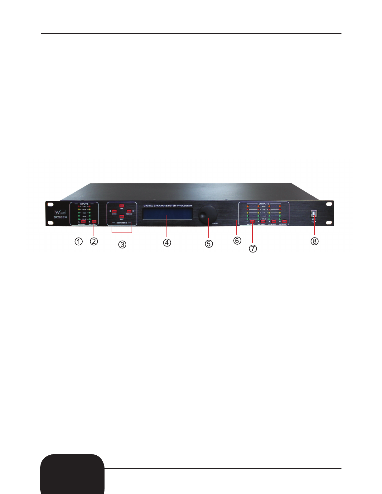
Front Panel
1) Input level indicators: 5 precision LEDs show the amount of input level on each channel
2) Input Mute button: Mutes the selected input channel.
3) Edit buttons:
“UTIL”: Chooses the systems menu.
“SAVE”: Saves the current setup and acts as a up button.
“RECALL”: Recalls past saved preset settings and acts as a down button.
“EXIT”: To exit each function.
4) LCD display: Shows the status of the current mode.
5) Parameter control: Edits and confirms the parameter presets.
6) Output level indicators: 4 precision LEDs and 1 signal LED shows the current state of
the output level on each channel.
7) Output Mute button: This button mutes the selected output channel.
8) USB connector: To connect to the PC and control equipment.
4
5
5
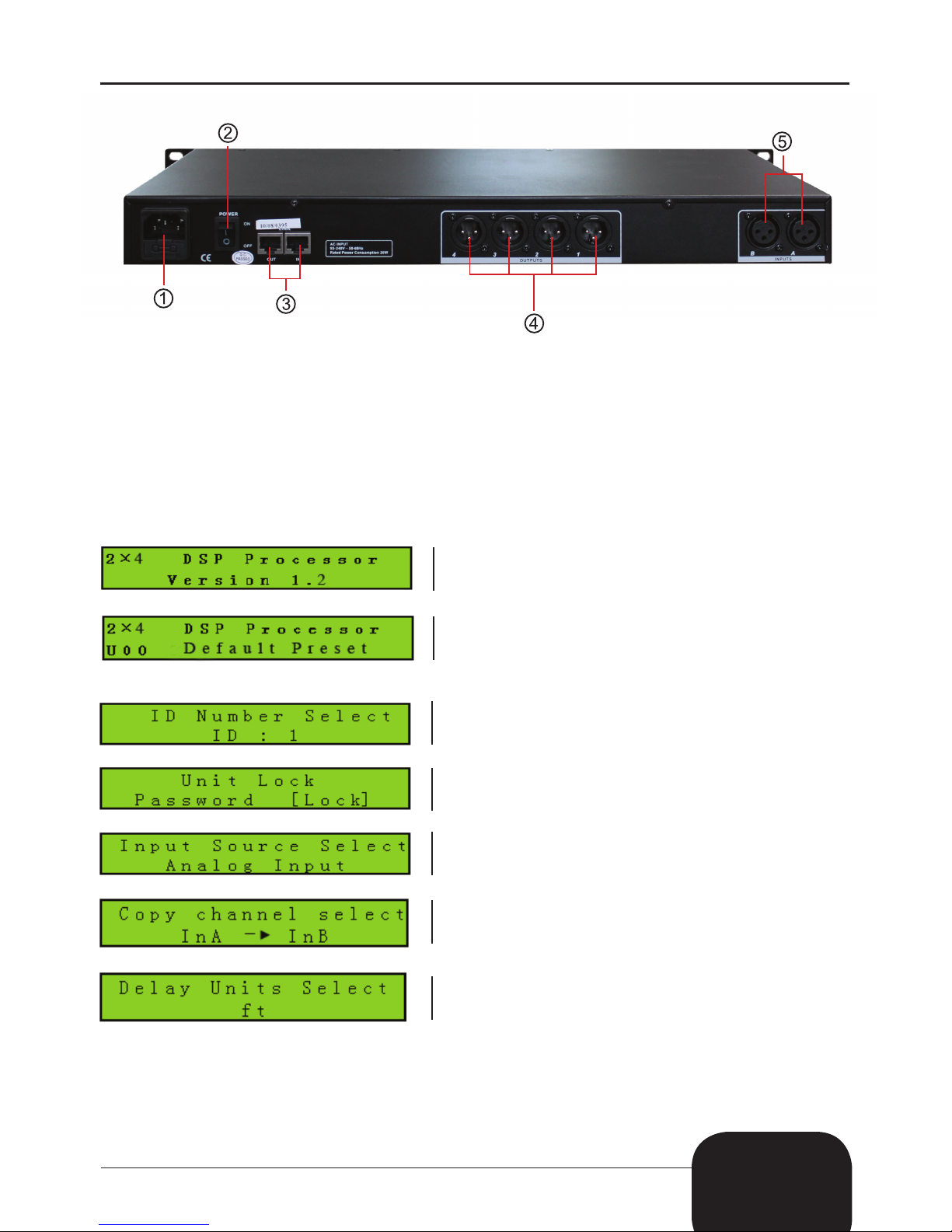
Rear Panel
1) Input power supply: Connects the IEC power cable
2) On/Off switch: Powers the unit on and off.
3) In/Out link sockets: To link further units or to connect to a PC
In: CAT-5 cable - 1-Pin RS-485+, Out: CAT-5 - 2-Pin RS-485-
4) 3-Pin XLR output sockets (1 -8)
5) 3-Pin XLR input sockets (A-D)
Operation:
To operate the unit please follow the instructions below;
To enter the ID setting for the first time please follow the instructions below.
1. On power up, the unit will show the brand, model and the software version.
2. Once it has finished self checking the LCD display will show the brand, model and the
current preset status.
1. To enter an ID for the first time press the “UTIL” button and choose from 1-254.
If there is more than 16 units to be linked or if there is a long distance between each
link a parallel connection is needed with a 120Ω resister on the end of the RS-485 cable.
2. Now press the “UTIL” button to enter a protection code, the code can either be a word
or a set of numbers.
Please note that the protection code is preset as “LOCK”.
3. Press the “UTIL” button a third time to enter a signal source setting.
Signal source setting include: pink/white noise and sine wave (20kHz-20kHz).
4. Press the “UTIL” button again to enter the copy menu function. You can now choose
between the input and output channels.
5. Now press the “UTIL” button a final time to enter a delay setting; ‘mS’, “m” or “ft”.
 Loading...