

Page 1
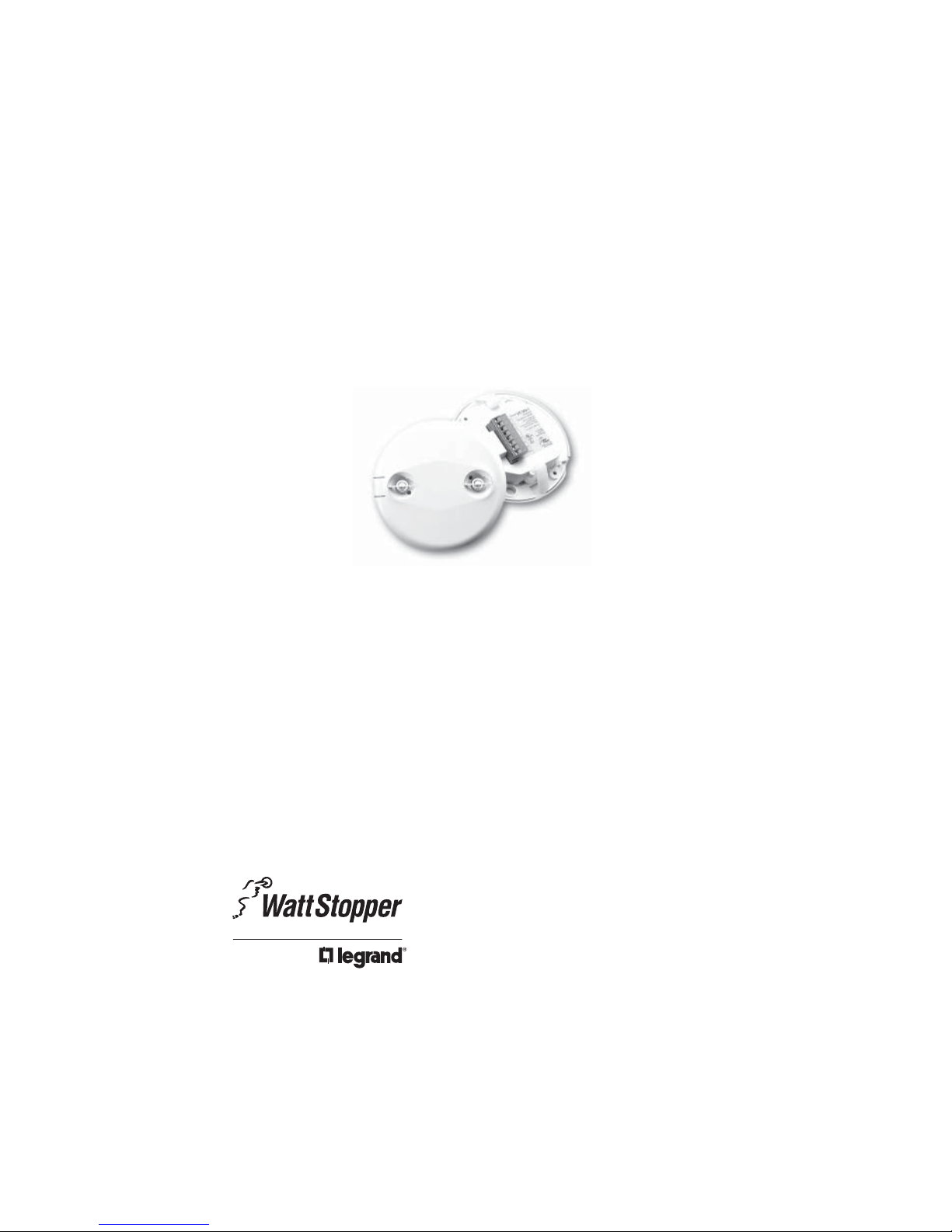
UT-300
Ultrasonic • Low Voltage
Occupancy Sensor
with Isolated Relay and Manual On features
Specifications
Voltage 18-28VDC/VAC, half wave rectifi ed AC
Current Consumption
Model UT-300-1, Model UT-300-2 ..............................40mA
Model UT-300-3 ..........................................................45mA
Power Supply .................................Watt Stopper Power Packs
Isolated Relay Rating ......................................1A @30VDC/VAC
Operating Temperature ..................... 32° to 131°F (0° to 55°C)
Time Delay Adjustment .................................... 5 to 30 minutes
Walk-Through Mode ...3 minutes if no activity after 30 sec.
Test Mode .5 sec. upon intial power-up or DIP switch reset
Ultrasonic Coverage
Model UT-300-1 ................................................up to 500 ft
Model UT-300-2 ..............................................up to 1000 ft
Model UT-300-3 ..............................................up to 2000 ft
Sensitivity Adjustment ..........Minimum to Maximum (trimpot)
Frequency ........................................................................ 40kHz
Installation Instructions
2
2
2
U.S. Patents: 4,787,722
5,189,393
and Patent Pending
Page 2

UNIT DESCRIPTION
The Watt Stopper UT-300 sensors turn lighting systems on and off based on
occupancy.
The UT-300 can be confi gured to turn lighting on, and hold it on as long as it detects
cccupancy. After no movement is detected for a user specifi ed or SmartSet time (5
to 30 minutes) the lights are switched off. A “walk-through” mode can turn lights
off after only 3 minutes, if no activity is detected after 30 seconds of an occupancy
detection.
The UT-300 operates on 24V supplied by Watt Stopper Power Packs. The sensors
can operate on 24VDC, 24VAC, or half wave rectifi ed AC. UT-300 sensors also have
an isolated relay with Normally Open and Normally Closed contacts for interfacing
with HVAC or EMS systems.
COVERAGE PATTERN
The UT-300 is available in 3 models. Each model has a different size coverage
pattern. The coverage shown represents walking motion at a mounting height of
8 to 10 feet. For building spaces with lower levels of activity or with obstacles and
barriers, coverage size may decrease.
Call 800.879.8585 for Technical Support
Page 3

PLACEMENT GUIDELINES
Depending upon obstacles such as furniture or partitions, the area of coverage may
be less or more than the sensing distances shown in the coverage pattern. This
must be considered when planning the number of sensors and their placement. It is
also recommended to place the sensor 4 to 6 feet away from air supply ducts.
Mount the sensor to the ceiling. The UT-300 is designed for a ceiling height of about
8-10 feet. Mounting above or below this range will signifi cantly affect the coverage
patterns. As a general rule, each occupant should be able to clearly view the sensor.
Open Offi ce Area Coverage: To get complete coverage in an open offi ce area, install
multiple sensors so that there is approximately 20% overlap with each adjacent
sensor’s ultrasonic coverage area.
One UT-300
Coverage Area
20%
Ultrasonic
Overlap
Visit our website for FAQs: www.wattstopper.com
Page 4
WIRING DIRECTIONS
CAUTION
TURN POWER OFF AT THE CIRCUIT BREAKER BEFORE
INSTALLING POWER PACKS OR SENSORS.
Each Watt Stopper BZ series power
pack can supply power for 4 UT-300
sensors. When using more sensors than
this, multiple power packs are required.
03620r1
Refer to the wiring diagram on the next
page for the following procedures:
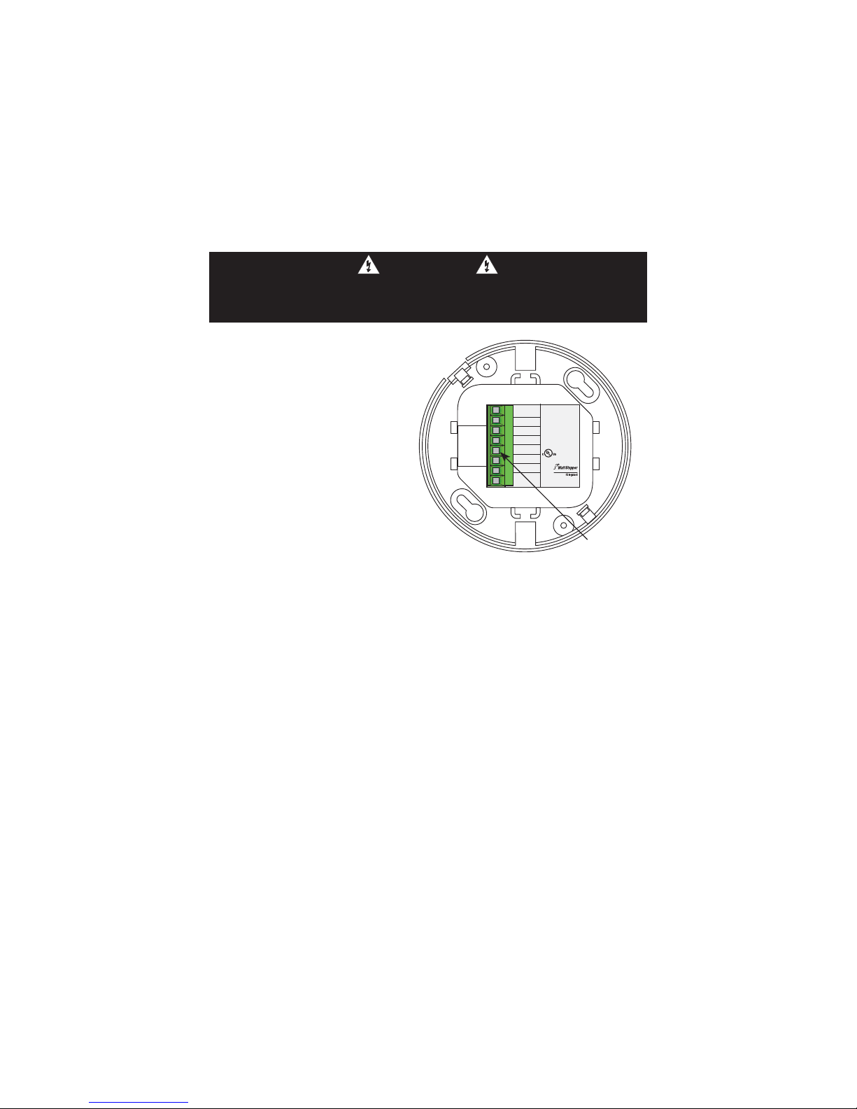
Connect the low voltage:
• RED wire (+24VDC) from power pack
to the +24V terminal on the sensor.
• BLACK wire (Return) from power
pack to Common terminal on the
sensor.
Wiring a SINGLE LIGHTING LOAD
CONTROLLED BY OCCUPANCY–connect:
• BLUE wire from power pack to Control Out terminal on sensor.
Relay Com.
Control Out.
Man. Switch
Common
Model#:
N.O.
N.C.
+24V
UT-300
Ultrasonic
Occupancy Sensor
40kHz Ultrasonic
+24VDC/VAC
Connect to Watt Stopper
Class 2 Power Packs
For Indoor Use Only
U.S.Patents:
5,124,566
5,640,113
Patent Pending
LISTED
88T9
Appliance
Control
Santa Clara, CA
800.879.8585
Wiring
terminals
To add a MANUAL SWITCH such as the LVS-1 Momentary Toggle Switch, or RS2-3
Low Voltage Momentary Switch to the above applications–connect:
• Wire from one side of switch to Common terminal on sensor.
• Wire from other side of switch to Man Switch terminal on sensor.
Wiring the ISOLATED RELAY: (The Isolated Relay is rated for 1A@30VAC/VDC)
Connect the wires necessary to the application that requires this output:
• Relay Common (must be used for proper operation)
• N.O. (Normally Open)–Closed when occupancy is detected
• N.C. (Normally Closed)–Open when occupancy is detected
Call 800.879.8585 for Technical Support
Page 5
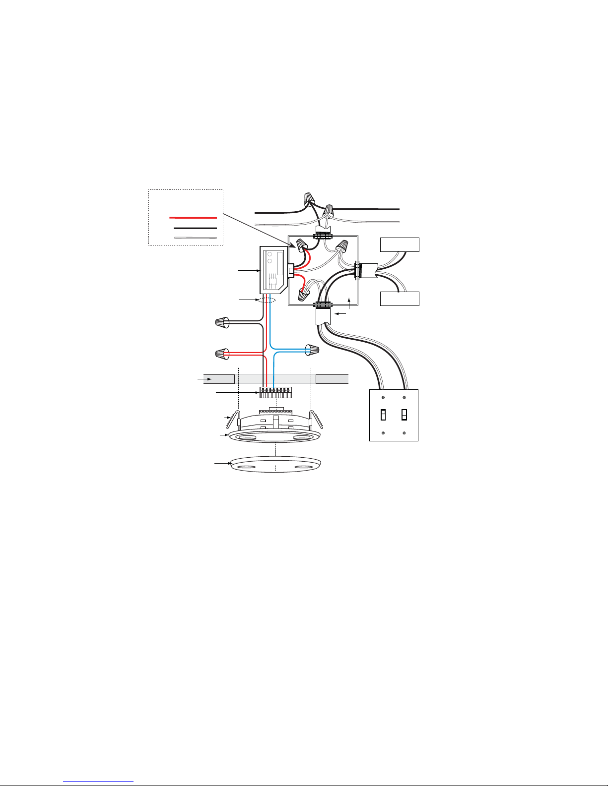
Standard wiring with local off switch
Line Voltage
Wire Color Legend
Red
Black
White
Power Pack
Line
Neutral
Feed Through
Load #1
Low Voltage
Class 2
Ceiling
Depluggable
Terminal
Spring Clips (2)
Rear Housing
Front Cover
Black
Common
Red
+24V
Blue
Control Out
UT-300
Line
Voltage
Load #2
(Optional)
#1 #2
Line Voltage
Switches
Visit our website for FAQs: www.wattstopper.com
Page 6
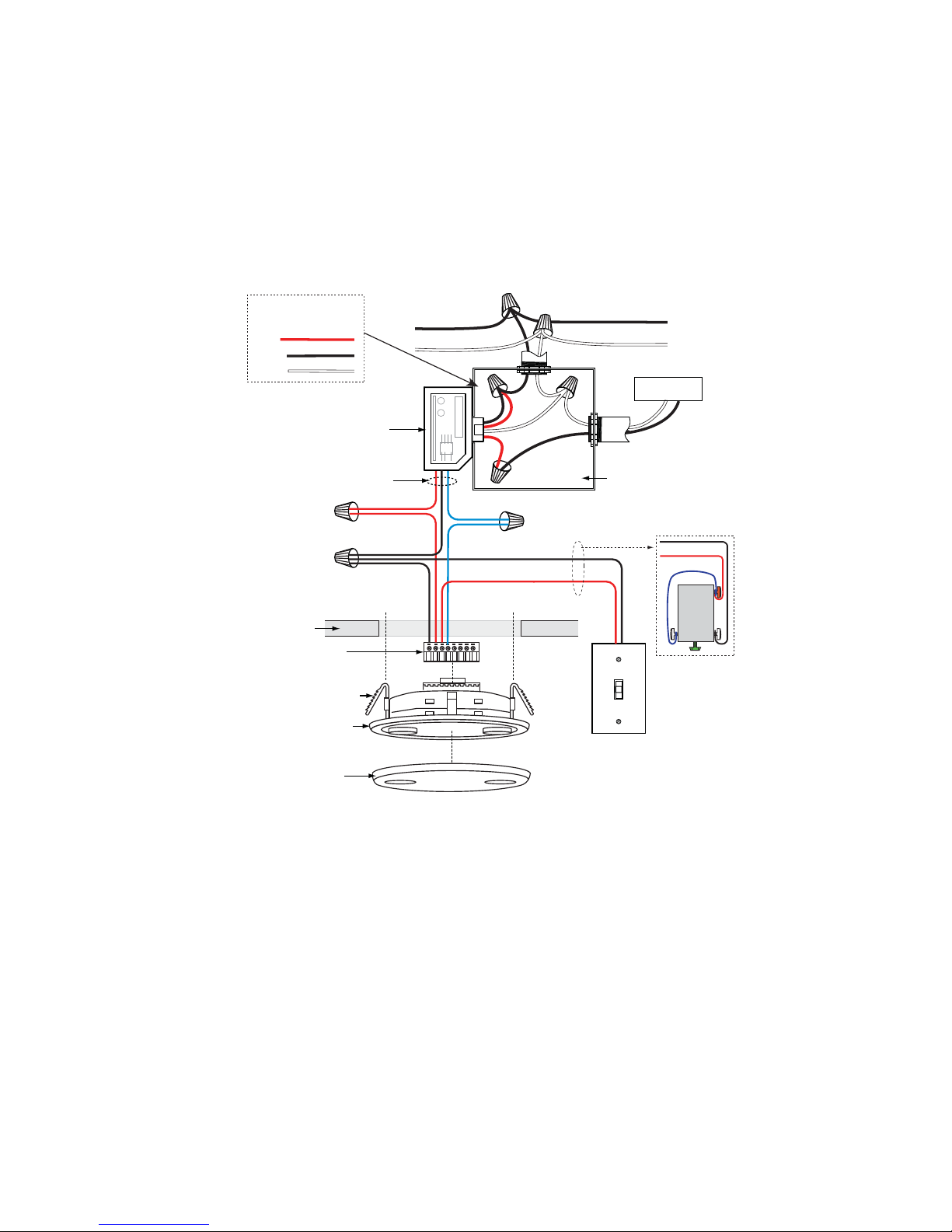
Manual-On wiring with low voltage momentary switch
Line Voltage
Wire Color Legend
Red
Black
White
Power Pack
Low Voltage
Class 2
Ceiling
Depluggable
Terminal
Spring Clips (2)
Rear Housing
Front Cover
Red
+24V
Black
Common
Line
Neutral
Blue
Control Out
Man. Switch
Feed Through
Load
Line Voltage
Common
Man.Switch
Jumper
Back
of
LVS-1
LVS-1
For low voltage
momentary switch, set
UT-300 DIP switch #1 ON
UT-300
Page 7
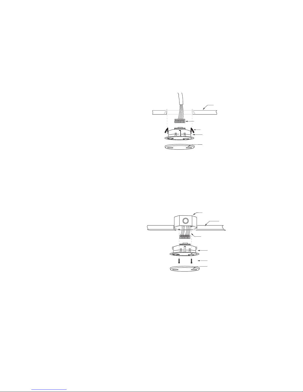
MOUNTING THE SENSOR
B
e
n
Directly to Ceiling
1. Attach the plastic spring clips to
the edge of the sensor in the slots
provided.
2. Cut a 3.5” to 4” round hole in
the acoustic ceiling tile at the
mounting location. A 3.5” hole is
recommended for a secure fi t.
3. Pull the low voltage wire from the
power pack to the sensor through
the hole.
4. Connect the low voltage wires to
the appropriate terminals on the
sensor.
5. Push the sensor up through the
hole until the Spring Clips hold the
sensor securely in place.
6. Snap the front cover onto the
sensor.
Ceiling
Depluggable terminal
Spring clips (2)
Rear
housing
Front
cover
Ceiling Mount
Using an Octagonal J-Box
1. Pull the low voltage wires from the
4" Octagonal J(at least 1.5" de
power pack into the J-Box through
the conduit knockout.
2. Connect the low voltage wires to
the appropriate terminals on the
Depluggable
Terminal
sensor.
3. Loosen the appliance mounting
screws attached to the J-Box
4. Align the sensor in the J-Box so
that the mounting screws on the
box match the key holes on the
sensor’s rear housing.
J-Box Mount
Rear
Housing
Screws
Front
Cover
5. Push the sensor up into the J -Box and twist it so that the mounting screws are
seated in the keyhole slots.
6. Tighten the two screws to secure the sensor to the J-Box.
7. Snap the front cover onto the sensor.
Call 800.879.8585 for Technical Support
Ceili
Page 8

SENSOR ADJUSTMENT
The sensors are factory preset to allow for quick installation in most applications.
Verifi cation of proper wiring, coverage, and customizing the sensor’s settings can
be done using the following procedures. To make adjustments, open the Front Cover
with a small screwdriver.
Before making
adjustments, make
sure the offi ce
furniture is installed,
lighting circuits are
turned on, and the
HVAC systems are in
DIP switches
Ultrasonic
transducer
cones
E
C
E
8
7
6
5
4
N
3
O
2
1
the overridden/ on
position. VAV systems
should be set to their
highest airfl ow. Set
the Time Delay to the
Ultrasonic
activity
LED (Green)
desired settings. See
“DIP Switch Setting”,
next page.
To Test Occupancy Sensors
1. Ensure the Ultrasonic Activity LED is enabled (DIP switch 6 ON).
2. Ensure the Time Delay is set for Test Mode* using the “5 seconds/SmartSet”
setting. (DIP switches 3, 4, & 5 are OFF).
3. Ensure that the Ultrasonic Sensitivity trimpot is set to about 90%, clockwise.
4. Remain still. The LED should not fl ash. The lights should turn off after 5 seconds.
(If not, see “Troubleshooting.”)
5. Move about the coverage area. The lights should come on. Adjust the Ultrasonic
Sensitivity as necessary to provide the desired coverage (Green LED indicates
activation from the ultrasonic sensor).
When testing and adjustment is complete, reset DIP Switches to the desired
settings, and replace the cover on the sensor.
* Test Mode is a temporary state that starts when you fi rst set the sensor’s DIP
switches for the “5 sec/SmartSet mode” (switches 3, 4, 5 OFF). If you need to
invoke the Test Mode and the DIP switches are already set for 5 sec/SmartSet,
toggle DIP switch 5 ON then back to the OFF position. This provides a 5 minute
test period. During the test period, the Time Delay is only 5 seconds.
Visit our website for FAQs: www.wattstopper.com
Keyhole slots
(for mounting to
4" octagonal box)
Ultrasonic
sensitivity
trimpot
Double gang
mudring
mounting holes
Page 9
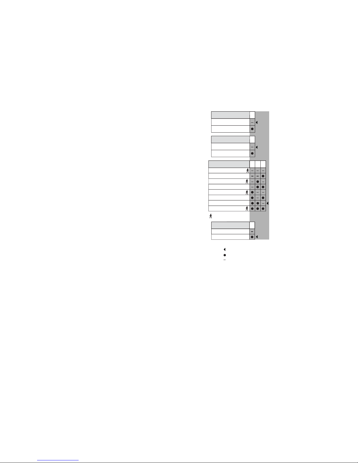
DIP SWITCH SETTING
The UT-300 has 6 DIP switches. They are used to set
manual/automatic on/off functions, time delay and
sensor activation LED settings.
On Mode: Switch 1
The Manual ON function is facilitated by installing
a momentary switch such as a Watt Stopper LVS-1
Momentary Toggle Switch, or RS2-3 Low Voltage
Momentary Switch. This switch connects to the
sensor’s Manual (Man.) Switch and Common terminals
as shown in the wiring diagram. Each time the switch
is pressed, the load changes state. The sensor’s
operation as related to the manually operated switch is
determined by the setting for DIP switch 1.
Manual On: In this mode, the switch is required to turn
on the load. The sensor is then used to keep the load
on, based on occupant activity. After the time delay
ends the manual switch must be used to turn the load
on, if there is no movement detected within the 30
second re-trigger period.
Automatic On: This mode uses occupancy as well as
switch activation to turn the load ON. A manual switch
provides the following additional functionality:
Logic Confi guration Chart
On Mode
Auto On
Manual On
Override
Normal
Override
Time Delay
5 sec/SmartSet
5 minutes
10 minutes
10 minutes
15 minutes
15 minutes
20 minutes
30 minutes
1
2
345
= walk-through mode
LED
6
Disabled
Enabled
= Factory Setting
= ON
= OFF
a. The load can be turned ON by manual switch
activation and it stays on as long as occupancy
is detected. The sensor time delay operates as
programmed. When the load turns OFF due to lack of occupancy detection, the
load can be turned ON again by occupancy detection or switch activation.
b. Activating the manual switch while the load is ON turns the load OFF.
• When the load is turned OFF manually, as long as the sensor continues to detect
occupancy the load stays OFF. Five minutes after the last occupancy detection,
the lights stay off and the sensor reverts to the automatic-on mode.
• When the load is turned OFF manually, pressing the switch again turns the load
ON and the sensor reverts to the automatic-on mode.
• Once the sensor returns to automatic-on mode, either the switch or occupancy
detection can turn the load ON.
Visit our website for FAQs: www.wattstopper.com
Page 10

Override: Switch 2
To override all sensor functions, set DIP switch 2 to the ON position. The green LED
comes on and stays on for the duration of the override.
This bypasses the occupancy detection control functions of the sensor, but still
allows the lights to be manually controlled with a light switch, if one is installed.
Time Delay: Switches 3, 4, 5
The sensor will hold the lights on as long as occupancy is detected. The time delay
countdown starts when no motion is detected. After no motion is detected for the
length of the time delay, the sensor will turn the lights off. The sensor can select the
time delay using SmartSet, or you can select a fi xed time delay.
• SmartSet records occupancy patterns and uses this history to choose an optimal
time delay from 5 to 30 minutes. SmartSet behavior starts immediately and is
refi ned continually as history is collected.
Walk-through mode turns the lights off three minutes after the area is initially
occupied, if no motion is detected after the fi rst 30 seconds. If motion continues
beyond the fi rst 30 seconds, the selected time delay applies.
LED: Switch 6
When enabled, the green Ultrasonic Activity LED on the sensor will light when the
sensor detects motion.
Call 800.879.8585 for Technical Support
Page 11

TROUBLESHOOTING
CAUTION
TURN POWER OFF AT THE CIRCUIT BREAKER
BEFORE WORKING WITH OR NEAR HIGH VOLTAGE.
For any unexpected operation
1. Check DIP switch settings.
2. Make sure the switches are set according to the defi ned settings in the DIP
Switch Setting chart.
Lights do not turn on with occupancy, and the LED does not fl ash:
1. DIP switch #6 must be ON to enable the LED.
2. Check that the circuit breaker has been turned back on.
3. The Ultrasonic Sensitivity setting may need to be increased.
Turn clockwise as needed.
4. Check all sensor and power pack wire connections.
5. Check for 24V input to the sensor.
- If 24V is present, replace the sensor.
- If 24V is not present, check that high voltage is present to power pack.
If it is, replace power pack.
Lights do not turn off automatically:
1. The sensor may be experiencing activations from outside the controlled area or
from some type of interference (see “Unwanted Sensor Activations” below).
2. Check all sensor wire connections.
3. Disconnect power pack’s blue wire:
If the lights do not turn off, replace power pack. Reconnect blue wire.
If the lights turn off, the problem may be in the sensor–to check:
Reconnect the blue wire.
Turn sensitivity and time delay to minimum and allow the sensor to time out.
If the lights turn off, the sensor is working properly (see number 1, above, and
“Sensor Adjustment” for readjustment of sensor).
4. Set sensitivity and time delay to minimum and allow the sensor to time out.
If the lights turn off, the sensor is working properly (see number 1, above, and
“Sensor Adjustment” for readjustment of sensor).
Visit our website for FAQs: www.wattstopper.com
Page 12

Unwanted Sensor Activations (LED fl ashes):
• Possible causes
1. The ultrasonic sensitivity may be too high causing detection outside of desired
coverage area.
2. Sensor located too close to HVAC or VAV vents with heavy air fl ow.
• Possible solutions
1. Reduce the ultrasonic sensitivity (counterclockwise) as needed (see “Sensor
Adjustment”).
2. Relocate the sensor.
ORDERING INFORMATION
Catalog # Description
UT-300-1 Ultrasonic Occupancy Sensor, up to 500 sq ft coverage,
Low Voltage w/Isolated Relay and Manual On feature
UT-300-2 Ultrasonic Occupancy Sensor, up to 1000 sq ft coverage,
Low Voltage w/Isolated Relay and Manual On feature
UT-300-3 Ultrasonic Occupancy Sensor, up to 2000 sq ft coverage,
Low Voltage w/Isolated Relay and Manual On feature
UT-305-1/2/3 Ultrasonic Occupancy Sensor, Low Voltage
BZ-50 Power Pack: 120/230/277VAC, 50/60Hz, 225mA, 20A ballast
or incandescent, 1HP@120/250VAC
BZ-150 Power Pack: 120/230/277VAC, 50/60Hz,
225mA, 20A ballast or incandescent, 1HP@120/250VAC
S120/277/347E-P Auxiliary Relay Pack: 120/277VAC, 60Hz, 20A Ballast
347VAC, 60Hz, 15A Ballast
All sensors are white.
B series power packs supply power for up to 3 UT-300 sensors.
BZ series power packs supply power for up to 4 UT-300 sensors.
Call 800.879.8585 for Technical Support
Page 13

WARRANTY INFORMATION
The Watt Stopper, Inc. warranties its products to be free of defects in materials
and workmanship for a period of fi ve years. There are no obligations or liabilities
on the part of The Watt Stopper, Inc. for consequential damages arising out of or in
connection with the use or performance of this product or other indirect damages
with respect to loss of property, revenue, or profi t, or cost of removal, installation or
reinstallation.
Please
2800 De La Cruz Boulevard, Santa Clara, CA 95050
Technical Support: 800.879.8585
www.wattstopper.com
03630r2 10/2008
Recycle
 Loading...