

Page 1
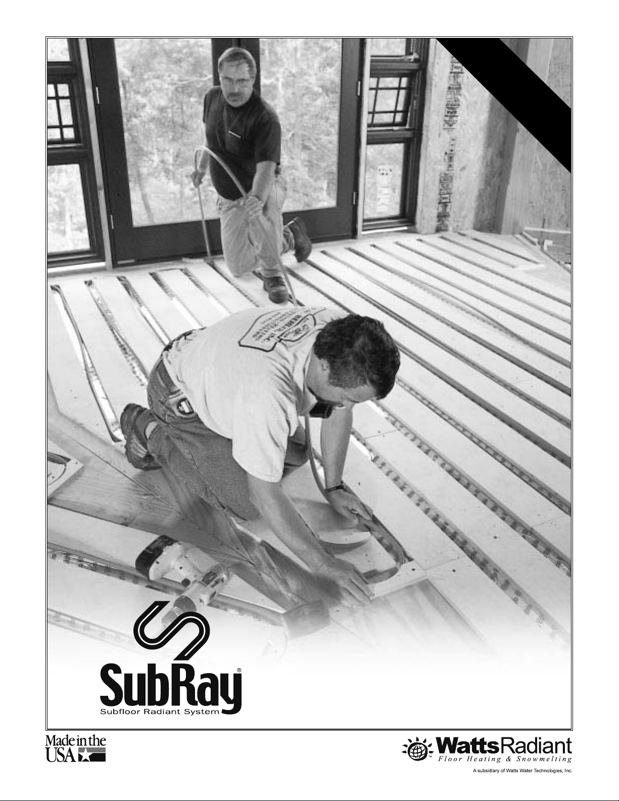
Installation
Installation
Manual
Manual
44..0
0
4.0
Page 2
2 SubRay Installation Manual
Benefits of the SubRay® System
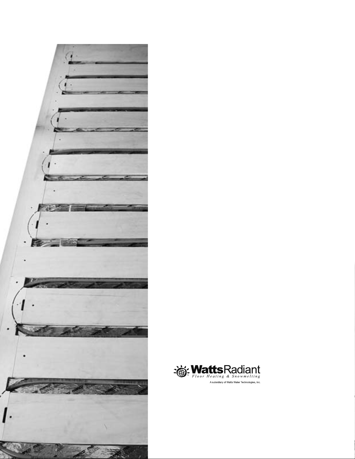
SubRay is a safe, practical, and easy way to install radiant
floor heating over frame or slab floors. SubRay can be
installed as a whole-house heating system, or used to heat a
basement or room addition.
See the Watts Radiant Product Catalog or visit us on the Web at
www.wattsradiant.com for an entire list of hydronic and
electric radiant heating/snowmelting equipment.
Features of the SubRay System
• FAST — Quick and easy installation.
• CLEAN — No messy silicone needed.
• BIGGER ZONES — Twice the flow-rate of 5/16” PEX.
• SILENT — Silent floating RadiantPEX
• THIN — Less than 5/8” thick (with 3/8” RadiantPEX).
• THREE PIPES — 3/8” and 1/2” RadiantPEX, and 3/8” Onix.
®
/Onix™ design.
• COMFORTABLE — The best heat there is.
• FLEXIBLE
• LIGHTWEIGHT — Easy-to-carry parts.
• QUALITY — High quality, 7-ply, Douglas Fir, boat grade plywood
and cabinet grade Group 1 Baltic Birch that meets the specs
of all wood flooring manufacturers.
• ECONOMICAL — Does not require constant circulation. Uses
standard pipes and fittings.
— Accommodates odd-sized rooms.
Tools Required
• Saw
• Flat-blade screwdriver
• Hammer
• Rubber mallet
• Tape measure
• RadiantPEX Unwinder or Onix Unwinder
• Radiant Tubing Cutter
• Chalk line
FREE Design
Call 1-800-276-2419 for free design assistance on any
SubRay installation.
(NYSE WTS)
4500 E. Progress Place
Springfield, MO 65803-8816
800-276-2419 (USA and Canada)
417-864-6108 (phone)
417-864-8161 (fax)
www.wattsradiant.com
Page 3
Quality Construction
European Baltic Birch is kiln dried, won’t splinter or crack,
and holds nails and screws better than any constructiongrade plywood. Sleepers are made from a high quality, 7-ply,
Douglas Fir, boat grade ply wood that is finished and sanded
on both sides. Both Birch and Douglas Fir compnents are
made of multiple thin laminations for dimensional stability.
Order 15 mm components for use with 3/8” RadiantPEX;
order 18 mm components for 1/2” RadiantPEX and 3/8”
Onix piped systems. All SubRay products are made of either
Baltic Birch or Douglas Fir.
Note: Ends of 15-mm Birch parts are color-coded red;
18-mm parts are color-coded blue.
SubRay Component and
Accessory List
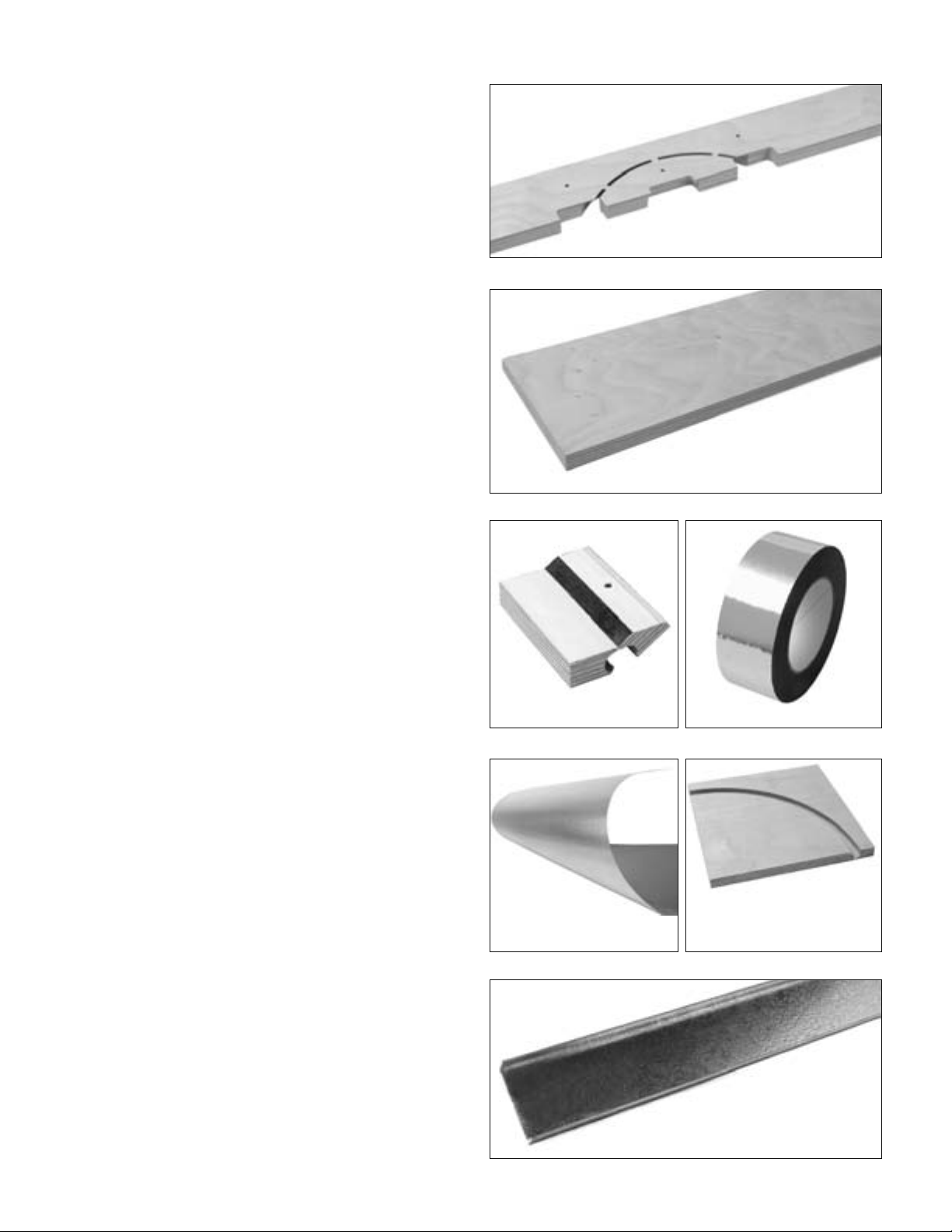
Header Sticks (Fig. 1).
Header Sticks hold radiant pipe at each end of the room and
spaces it on 8” centers. When installing hardwood strip flooring, you must run header sticks parallel to
the flooring at both ends of the room. If using other
flooring types, run header sticks along both short sides
of the room.
SubRay Installation Manual 3
Fig. 1. Header Sticks.
Fig. 2. Sleepers.
Sleepers (Fig. 2).
Sleepers are 6” wide and are installed 2” apart. They support the finish floor and provide a radiant channel for the piping to be safely installed. Allow about 30 Sleepers per 100
sq. ft. of floor.
Grippers (Fig. 3).
Grippers are used to hold RadiantPEX where it enters
or exits the floor so that the pipe will not rub against
floor penetrations. Allow two for each RadiantPEX circuit.
Not needed for Onix installations.
Radiant Tape (Fig. 4).
Radiant Tape is applied to the bottom of each radiant channel to reflect the radiant energy upward to the floor. Use a
tape dispenser; allow one roll for every 240 sq. ft.
Aluminum Conduction Rolls (Fig. 5).
Aluminum Conduction Rolls are installed over the top of the
Sleepers, and help disperse the heat more evenly. Use one
roll for each 70 sq. ft. of floor.
Corner Sweeps (Fig. 6).
Corner Sweeps help RadiantPEX make a 90° turn. Most
simple rectangular rooms will need two sweeps per pipe circuit; most cut up complex rooms will need 5–15 sweeps per
circuit. Not needed for Onix installations.
Fig. 3. Grippers.
Fig. 5.
Aluminum Conduction Roll.
Fig. 4. 2” Radiant Tape.
Fig. 6. Corner Sweep.
C-Covers (Fig. 7).
C-Covers are heavy steel “U” guards that protect pipe from
nails, and are used to support tile backer board. Most commonly they are used to protect supply/return lines that run
parallel to strip flooring.
Fig. 7. C-Cover.
Page 4
4 SubRay Installation Manual
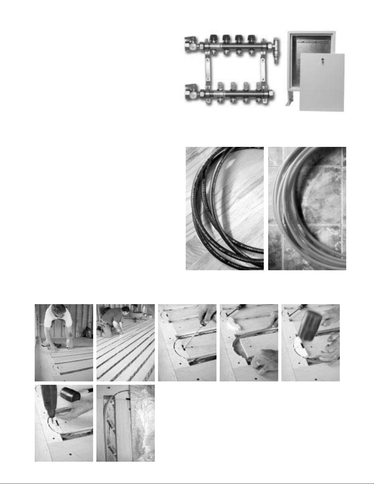
Manifolds (Figs. 8 and 9).
Manifolds distribute hot water to the radiant circuits in
the floor. Manifolds are installed as pairs. We suggest
using manifolds with shut off and/or individual circuit
balancing valves. Manifolds can be installed in walls,
under frame floors, in utility closets, mechanical rooms,
inside cabinets, or in any other accessible spot.
Zones
Zones are areas controlled by a shared thermostat or
other control. A zone may be one room or several rooms,
but all the radiant heating circuits for a zone will usually
originate and return to a single manifold location.
Radiant Tubing (Figs. 10 and 11).
Radiant Tubing transfers hot water or glycol/water
through the radiant channels in a SubRay system.
The red-coded 15-mm SubRay system is designed for
3/8" ASTM Watts Radiant RadiantPEX radiant tubing.
The blue-coded 18-mm SubRay system is designed
for use with both Watts Radiant 1/2" RadiantPEX, or
3/8" Onix radiant tubing.
Fig. 10. Onix radiant hose.
Fig. 11. RadiantPEX tubing.
Fig. 8. Watts Stainless Steel
manifolds with circuit balancing
and circuit flow indicators.
Fig. 9. Manifold Box.
The SubRay Radiant System Installs Fast and Easy.
Fig. 12. Installing the SubRay 862 Radiant System.
(a). Lay out Header Sticks and 6" Sleepers.
(b). Lay down 2" aluminized tape in the radiant channels.
(c). Use a screwdriver to pop up the removable Header Plate.
(d). Take the slack out of the RadiantPEX in the radiant channel. Then
push the tube into the header groove.
(e). Tap the Header Plate in place with a rubber hammer or step on it.
(f). Put in a screw in the hole provided.
(g). Lay the aluminum conduction roll over the wood and tube.
(b)
(c)
(d)
(e)
(g)
(a)
(f)
Page 5
SubRay Installation Manual 5
Fig. 13. Run your tubing to the far corner of the room and build
your SubRay floor back to the manifolds.
Recommended.
Fig. 15. Building your SubRay floor to the center of the room.
Not Recommended!
Fig. 14. Building your SubRay floor from the manifolds.
Not Recommended!
Important SubRay Design
Requirements
1. SubRay components are not structural, and
must be installed on top of structurally sound subfloors
or slabs.
2. Unless you protect the pipe with C-Covers or nail-
guards, do not install SubRay piping immediately next
to walls, in doorways, thresholds, or areas where you
might expect nails to be driven by flooring, trim, or
carpet installers. Be sure to allow for a perimeter strip
around the edge of the room.
3. Locate manifolds as close to the area to be
heated as you can. Supply and return manifolds can be
installed under floors, or in walls, but make sure they
are accessible.
4. Avoid running supply/return lines or manifolds in
exterior walls. Freeze damage may result.
5. Hardwood floors can be installed directly over the
SubRay system. Other floor finishes will require a minimum 1/4", 3/8", or 1/2" plywood to be installed over
the SubRay components. Read this manual’s directions
for your particular floor covering before proceeding. This
will ensure your finish floor heights will match.
6. Ask Watts Radiant or its professional reps to
perform a RadiantWorks™heat loss calculation to
ensure the boiler, pumps and system design meet the
structure’s heat load. This will include a list of radiant
pipe, manifolds, SubRay components and other materials required for each zone. After you have done a few
jobs you will probably feel comfortable doing your own
take-offs.
Planning the Installation
Planning Your Tubing Layout
Here’s a good rule of thumb: Once you have located
your supply and return manifolds, run your tubing circuit
to the far corner of the room and then build your SubRay
floor back to the manifolds. This is especially important
when you have a manifold above the SubRay floor
and there are multiple circuits of tubing in the zone.
Figure 13 shows this design practice, and if you plan
accordingly you can always get back to your manifold
from any place in the room. Figures 14 and 15 are not
recommended because if you build your SubRay floor
from the manifold or toward the middle of the room, you
will not have the space to return the end of the tubing
circuit(s) back to the manifold location.
Page 6
6 SubRay Installation Manual
Manifold and Circuit Selection
Using 3/8" Onix or RadiantPEX, most contractors will
run 200' circuits, although longer lengths are possible.
Using standard 8" spacing, and allowing for manifold
connections, a single 200' circuit will heat about
125 sq. ft.
Using 1/2" RadiantPEX, most contractors will run
300' circuits, which can heat about 200 sq. ft.
Therefore, if you are heating a 375 sq. ft. room, you
could select (3) 200' circuits, or (2) 300' circuits. You’ll
need to select a supply/return manifold set with the
correct number of branches to ser vice the circuits
you’re using for each zone. Remember that you’ll need
to use red-coded 15-mm SubRay components if you’re
using 3/8" RadiantPEX, and blue-coded 18-mm components if you’re using 1/2" RadiantPEX or 3/8" Onix. We
recommend Header Sticks if you’re using Onix, but you
won’t need to secure the removable Header Plate as
shown in Fig. 12e. See Watts Radiant’s RadiantPEX or
Onix Radiant Design and Installation manuals for more
information regarding tubing and manifold selection.
Note: We suggest using manifolds with individual
circuit shut-off valves on both supply and return circuits.
If your circuits are cut to special lengths, you should
use balancing valves if any circuit within a single zone
is more than 10% longer than the shortest circuit in
that zone.
Manifold Location
The location of the manifolds can change the pipe
layout, so this section of the manual gives you some
ideas regarding manifold placement. Remember that
manifolds must be accessible. The radiant tubing in the
floor begins and ends at the manifolds, so piping
access from the manifolds to the radiant floor is key.
Although there are many possible ways to install manifolds we will show you three popular methods.
Manifold Below the Floor
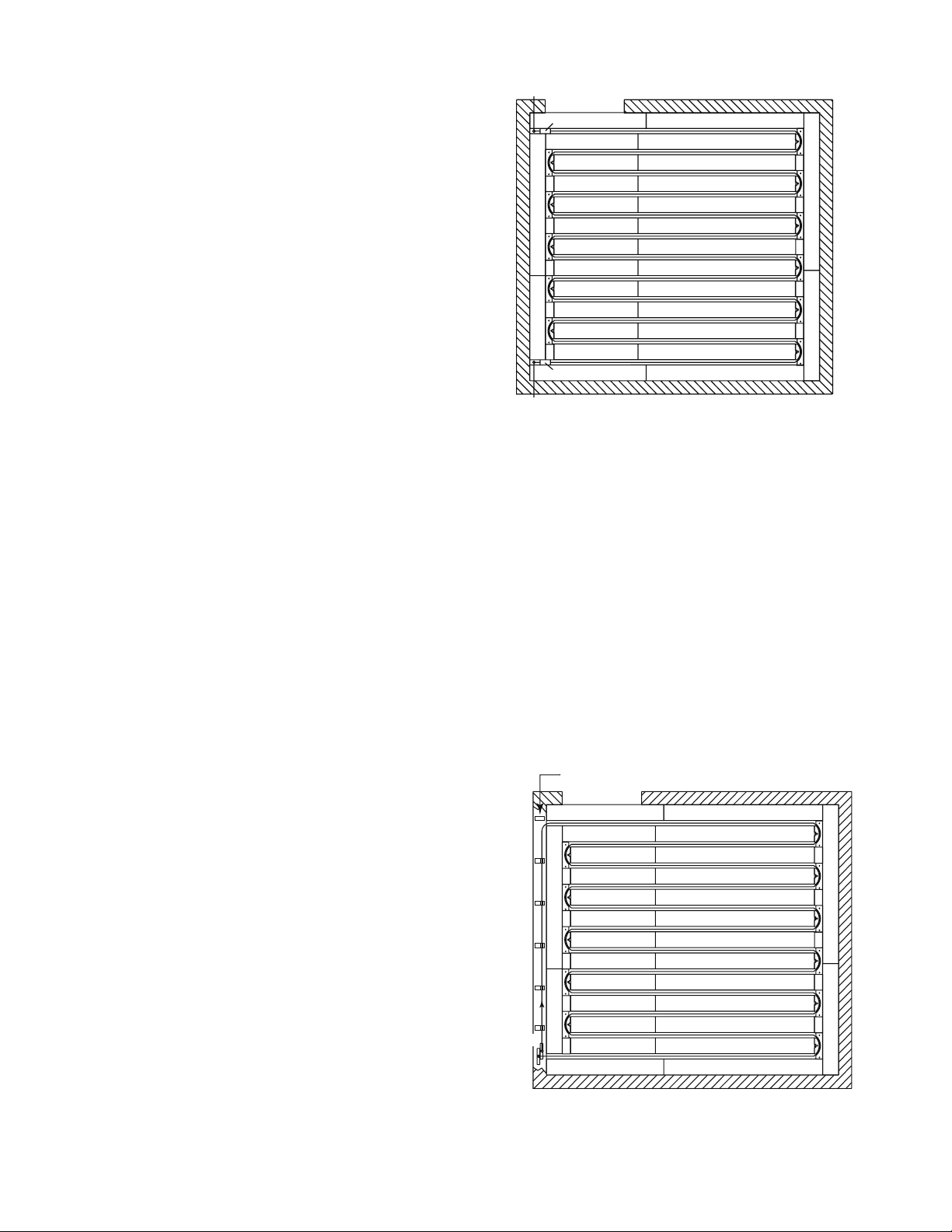
In Fig. 16 the radiant tubing enters the floor at one
end of the room and exits at the other end. The manifolds may be located under the floor, or at some remote
location. You can run one, two, or more circuits in the
same room using this method. Wherever you enter/exit
the floor, cut a minimum 2"–3" long slot so that the
radiant pipe will make a gentle upward bend, and not
kink, where it enters the floor. Use a Gripper at each
entry/exit slot to firmly hold the pipe in place, if you
are using RadiantPEX (Fig. 16).
Fig. 16. Loop configuration with manifolds below the floor
(manifolds not shown).
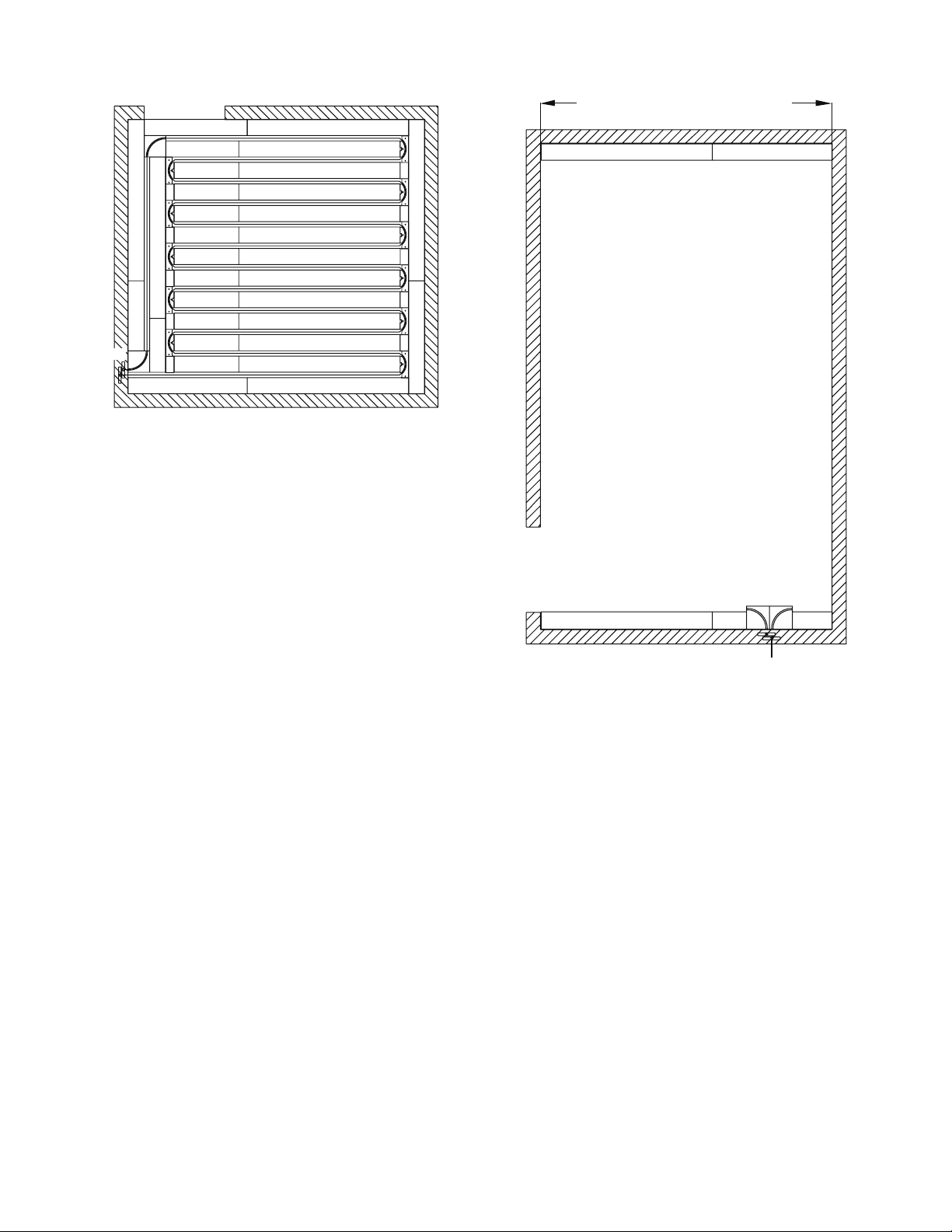
Manifolds Above the Floor
Manifolds may be installed in wall cavities, under
vanities, in mechanical closets, or adjoining rooms.
In Fig. 17 you’ll see a manifold in the wall, near a
room corner.
Tubing in Wall Studs
This approach keeps your floor layout very simple,
and is useful if you can run radiant piping through the
walls. The radiant tubing leaves the supply manifold,
runs through the wall studs and then to the far corner of
Fig. 17. Loop configuration with manifolds above the floor
with radiant tubing running through adjacent studs.
Pipe enters floor
Gripper location
Gripper location
Pipe exits floor
Stud wall (overhead view)
Manifolds
Page 7
SubRay Installation Manual 7
Manifolds
Fig. 18. Loop configuration with manifolds above the floor and
tubing in radiant channels.
the room. Then build your SubRay floor back to the
return manifold.
Don’t run piping through exterior walls, unless frostproofed with antifreeze. Cover the piping where it
enters/exits the wall with nail plates to protect it against
tack strips and trim nails.
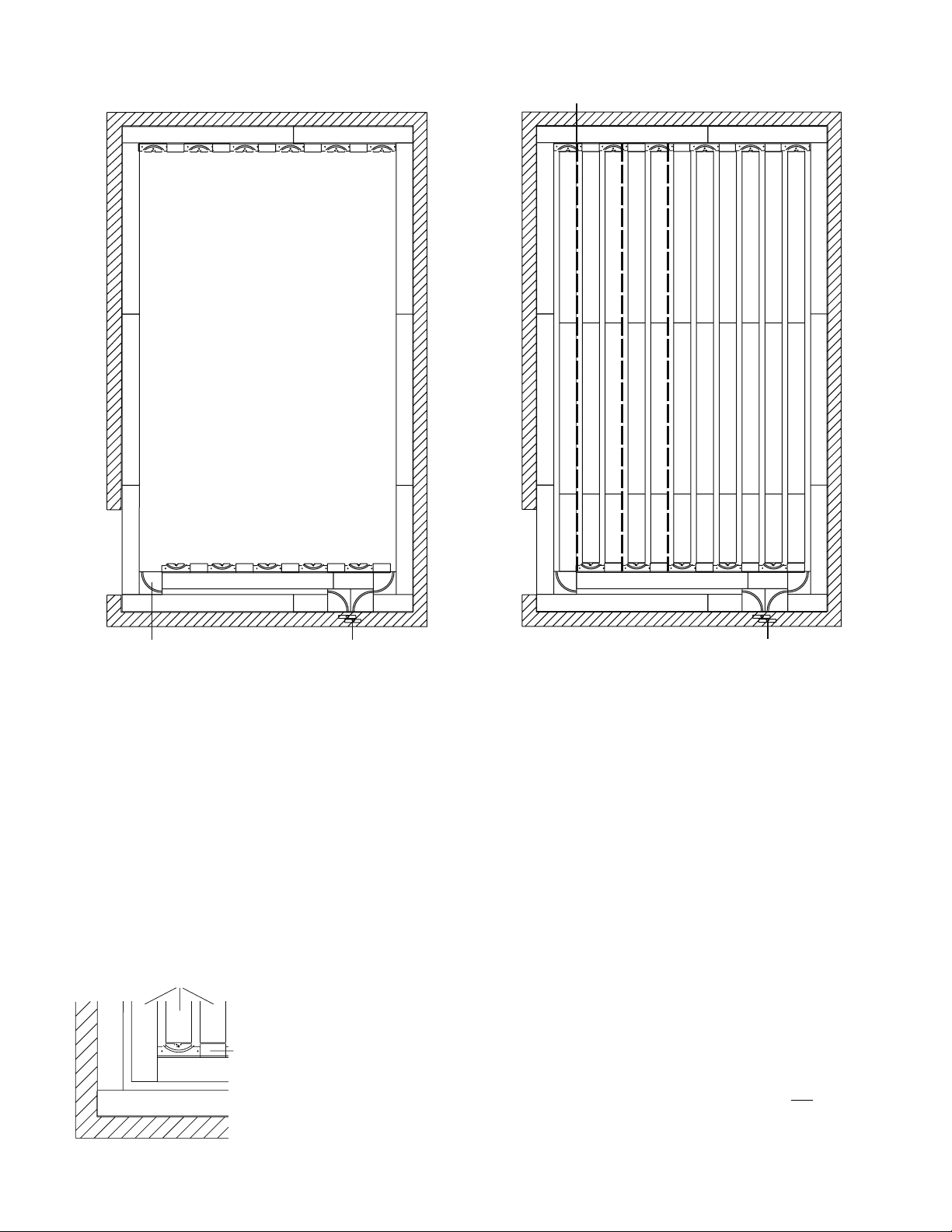
Tubing in the Floor Only
You may not have the option of running piping through a
wall, so locate your supply/return manifolds and cut a
slot or drill a hole in the wall base plate to form an entry
point for the radiant tubing. Install nail plates as needed
to protect tubing from base trim and carpet tack strips.
Form a radiant pathway for the tubing by installing a second sleeper, just after the perimeter sleeper strip on the
left wall. Run the radiant tubing up this pathway (Fig. 18)
along the left wall. If you are installing hardwood strip
flooring you will want to install a protective C-Cover over
the tubing because hardwood flooring will be running
lengthwise over this pathway. Run your radiant channel
to the far end of the room and build your Subray floor
back to the return manifold. (See also Fig. 35.)
Installation Steps
How to Begin
1. Select the two opposing walls of the room that the
Header Sticks will be installed next to (labeled Wall A
and Wall B in Fig. 19). Headers Sticks are normally
installed on the two short walls of a rectangular room.
If you are installing strip hardwood, the Header Sticks
must be installed parallel to (running with) the flooring.
Each Header Stick is 42" long and will hold three pipe
bends. The radiant circuits begin at the manifold and are
installed to run back and forth between the two sets
of Header Sticks.
2. Screw or nail standard SubRay 6" Sleepers in a
continuous strip along the two Header Stick walls (A/B)
(see Fig. 19).
Fig. 19. Planning the SubRay layout.
Direction of hardwood strip flooring (if used)
Wall A
Wall B
Manifolds
Page 8
8 SubRay Installation Manual
Installing Perimeter Strips and
Header Sticks
3. Measure the width of the room, between the two
walls that do not have Header Sticks (labeled Wall C
and Wall D in Fig. 20). Take this width (in inches) to
Appendix B (page 20) and see which width of perimeter
strips matches with your room width. In the example, a
120"-wide room (see span wall width in Appendix B, Fig.
43, page 20) will require 7" perimeter strips along walls
C and D. Rip up SubRay Sleepers as needed to make up
correct width and install the perimeter strips along walls
C and D.
Fig. 20. Installing Perimeter Strips and Header Sticks. Fig. 22. Installing Sleepers and Radiant Tape.
Fig. 21. Detail of corner for Onix
installation without Corner Sweep.
Due to its greater flexibility, Onix
does not require Corner Sweeps.
4. Fasten down the Header Sticks along the Header
Stick walls (A,B), add Corner Sweeps (see Fig. 20) as
needed. Corner Sweeps are not needed for Onix tubing;
see Fig. 21 for detail. Note: Fasten the removable
Header Plate only after radiant tubing is installed.
Important Note: Look ahead to Fig. 22 and see
how the Header Stick on wall B will always be offset by
one radiant channel (8") compared to the Header Stick
on wall A.
Installing Sleepers and Radiant Tape
5. Fill in Sleepers as shown in Fig. 22, maintaining
a 2" space between the Sleepers.
Note: Spacing of Sleepers is based on the Header
Sticks. It is recommended that a chalk line be made
between the opposing Header Sticks for the first
Sleeper and for every third or fourth Sleeper afterward
to make sure that the Sleepers are installed with the
2" spacing between them (see Fig. 22). Do not
use
Grippers as spacers.
6. Lay in radiant Reflective Tape in the 2" space.
Wall C
Wall A
Wall D
Wall C
Chalk line
Wall A
Wall D
Corner Sweep
Sleepers
Wall B
Manifolds
Wall B
Manifolds
Perimeter Strip
Channel
Perimeter Strip
Channel
Header Stick
Page 9
SubRay Installation Manual 9
Wall C
Fig. 23. Installing Radiant Tubing. Fig. 25. Installing Aluminum Conduction Layer.
Running Radiant Tubing
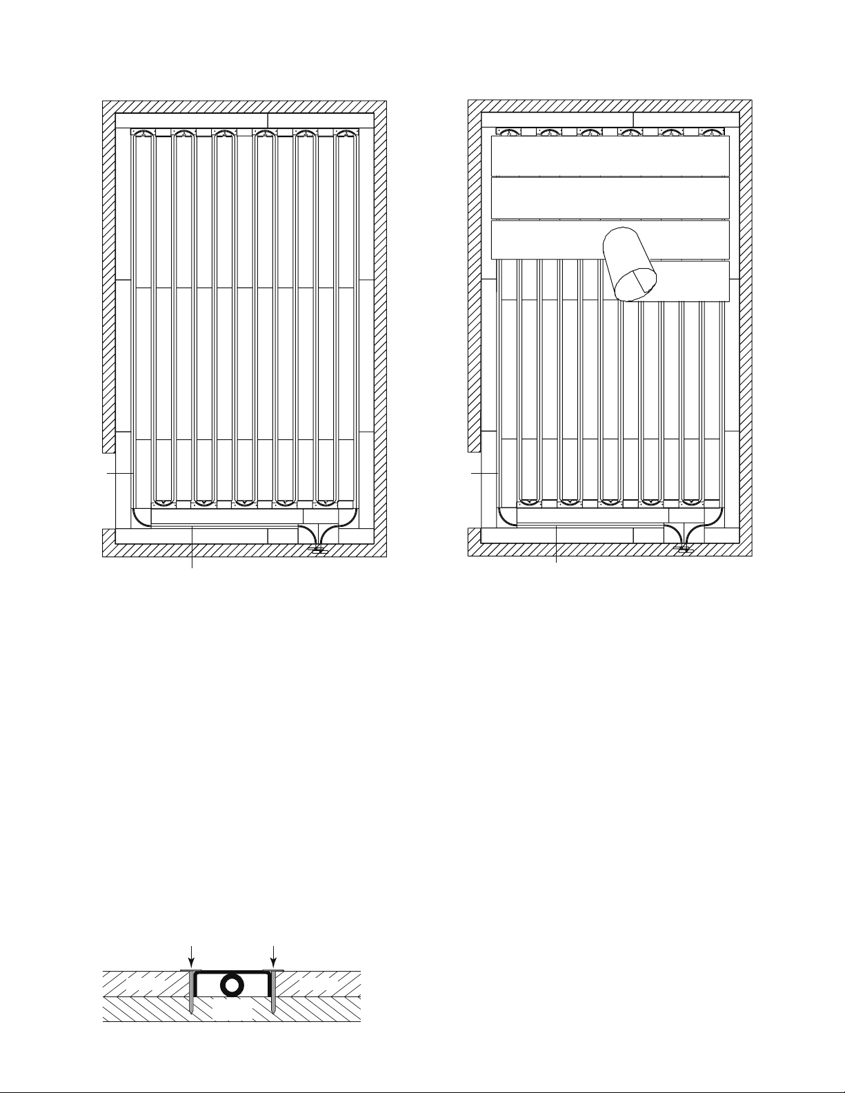
7. Beginning at the manifolds, run the radiant tubing
in the radiant channels (see Fig. 23). Try to avoid field
splices. Use Grippers where RadiantPEX enters or leaves
the floor, as necessary.
8. Cover vulnerable areas of radiant tubing with
C-Covers (Figs. 7 and 23) or nail guards as needed. Use
C-Covers anywhere radiant tubing is running parallel to
hardwood strip flooring. Because Onix is slightly thicker
than PEX, C-Covers over Onix may need to be secured by
driving roofing nails between the C-Cover and the
Sleepers (see Fig. 24).
9. When the piping in each zone is installed, connect
it to the manifolds. Use a Watts Radiant pressure test
kit, or equivalent, to pressurize each SubRay zone to
100 psi or as local codes require. If possible, pressurize
the system for 24 hours before rolling out the Aluminum
Conduction Rolls. You must pressurize the system for a
minimum of 24 hours before covering it with a permanent floor. After a 24-hour initial test, the system should
experience no more than a 10% loss of pressure.
Maintain a pressure in the system continuously until
the finish floor is installed and the base trim is installed.
Check the system frequently while other tradespeople
are working on the job to minimize the chance of concealed damage. Read the Watts Radiant RadiantPEX or
Onix manuals for essential pressure test procedures
and cautions before pressure testing. If a leak is suspected, check all connections and locations of possible
pipe damage before retesting the system. If you are not
sure how to proceed, please call Watts Radiant or your
local technical support person for advice.
Installing Aluminum Conduction Layer
10. Roll out the first Aluminum Conduction Roll (see
Fig. 25). Leave the Header Sticks exposed if you will be
nailing a finish floor down and need to see where the
radiant pipe is installed.
Fig. 24. Securing C-Covers over Onix radiant tubing.
Wall A
Aluminum Conduction Roll
Wall D
C-Cover
C-Cover
Wall B
Roofing Nails
(driven between Sleepers and C-Cover)
C-Cover
(over Onix)
Sleeper Sleeper
Plywood
Subfloor
C-Cover
C-Cover
Page 10
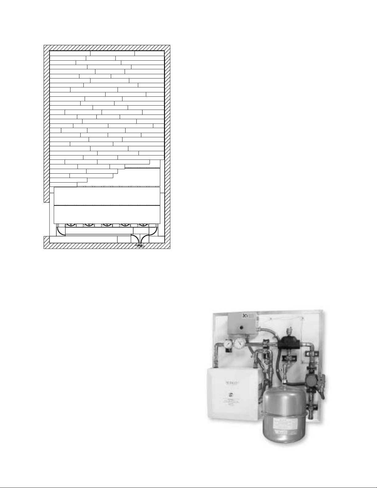
Fig. 26. Installing hardwood flooring.
11. Roll out the rest of the rolls, but leave a 1/2"
gap between them, so that you will be able to clearly
see where the pipes are located underneath.
Installing Finish Flooring
12. After consulting the section(s) of this manual
that apply to your finish flooring, cover the SubRay
System with the correct subfinish and finish flooring
materials (Fig. 26), as outlined in this manual and
required by the finish flooring manufacturer.
10 SubRay Installation Manual
Fig. 27. A Watts Radiant HydroControl maintains control over
the water temperature entering the SubRay zone.
Insulation
Adequate insulation will reduce fuel bills and increase
comfort. When SubRay is installed over a frame floor, it
is highly desirable to insulate under the floor, unless it is
physically impossible. If the lower floor is heated, you
should use a minimum R-13 batt under the floor. If the
area below is unheated, then use a R-19 to R-38 batt
under the floor. See following figures for illustrations of
various ways to insulate under floors.
If SubRay is installed over a new slab, the slab, especially the slab perimeter, should be insulated to at least
the standards of the local building code, although most
builders will add additional insulation. If installed over
an old slab, 1" to 3" of perimeter insulation should be
retrofitted.
If it is impossible to insulate under the floor consult
with Watts Radiant before proceeding.
Operating Guidelines
The SubRay system does not require costly or complex constant circulation systems to maintain even floor
temperatures. You may wish to use a Watts Radiant
dual-sensing stat that measures both air and floor
temperature, an outdoor reset system, or other control
option. Consult with your Watts Radiant representative
for technical assistance.
For maximum comfort, ASHRAE Guidelines suggest
that floor surface temperatures should not exceed
85°F in most living areas. Most floors will warm to
between 75° and 80° to meet the heat loss, perhaps
more during cold weather, or where a building is not
well insulated.
Some types of finished flooring are made of glues,
laminates, or polymers that may react adversely to
higher temperatures. When in doubt, check with the
flooring manufacturer regarding temperature limits for
their materials.
The water and surface temperatures can be controlled with a combination of Watts dual-sensing stats
(air/floor), preassembled HydroControl®Panels (see
Fig. 27) or other combinations. Always use the lowest
temperature necessary to maintain comfort. Do not
allow inlet water temperatures to exceed 160°F.
Hardwood Flooring
Aluminum Conduction Roll
Page 11
SubRay Installation Manual 11
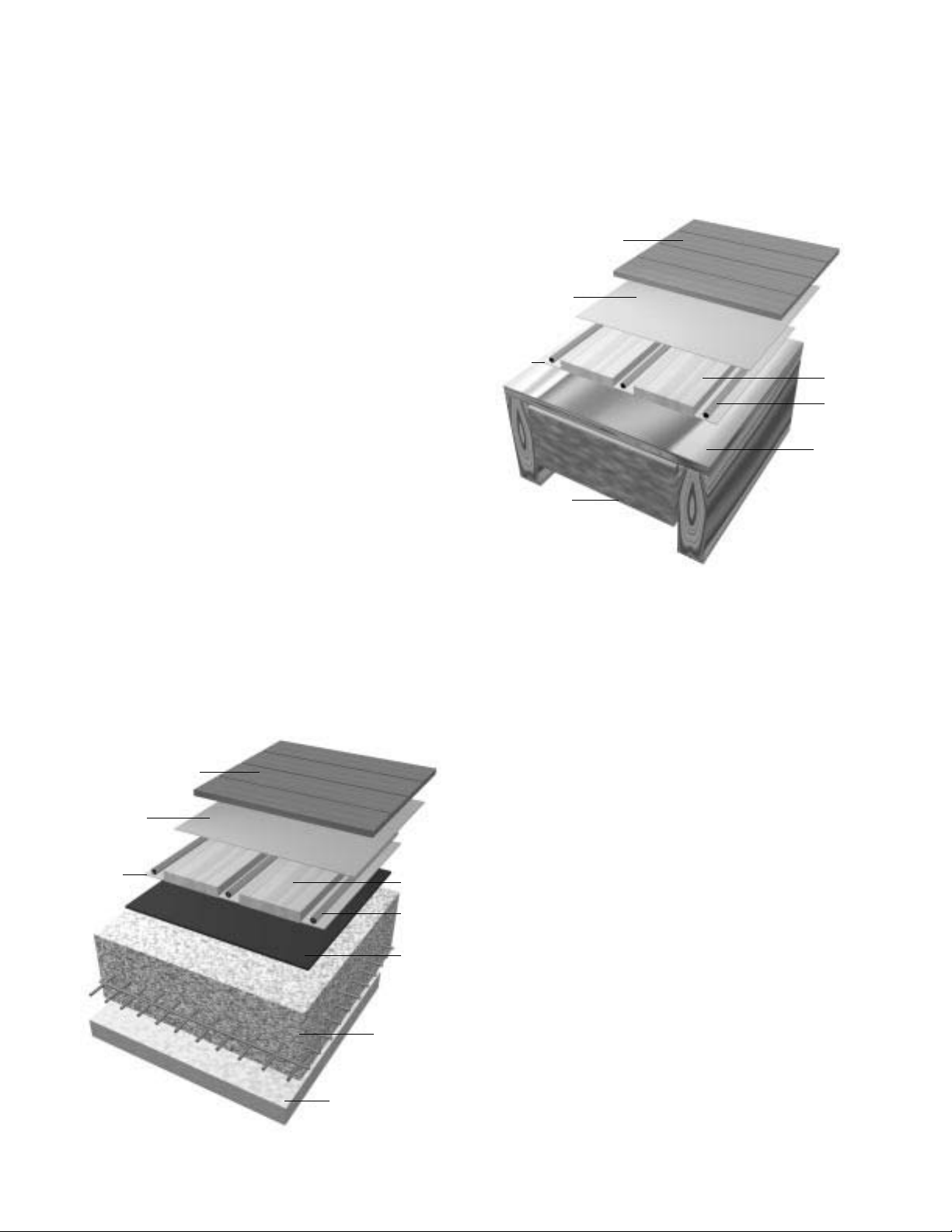
Fig. 28. Hardwood over SubRay system, over slab.
SubRay Installation and
Floor Surfaces
Natural Hardwood Flooring
Preparation of Slab. Secure Sleepers and Header
Sticks to the underlying slab on 8" centers. Concrete
nails may spall some concrete, and cause rocking.
If so, use concrete screws or bolts (see Appendix A for
details). We recommend you predrill the Sleepers before
drilling into the concrete. The slab must have a vapor
barrier installed underneath it to prevent ground moisture from coming up into the floor. If the slab is less
than six months old, or contains residual moisture, it
must first be aged or heated to drive out the moisture.
Tape down a 2' x 2' square of plastic over a section of
the slab and wait 24 hours. If there is no moisture present on the plastic sheet after this test, the concrete is
suitably dry for a wood floor to be installed over it. If in
doubt as to moisture content of the slab, or if installing
over an existing older slab; you must install a thick
(eight mil or better) vapor barrier over the slab. Overlap
and tape the edges of the barrier to prevent residual
concrete moisture from damaging the wood flooring.
The slab beneath must be insulated according to
local code and practices. In a retrofit of an existing
slab, it may not be possible to insulate the slab. See
your Watts Radiant representative for additional design
and installation concepts if you cannot insulate the slab.
Aluminum
Conduction
Roll
Sleepers
Radiant
Tubing
Radiant
Tape
Vapor
Barrier
Slab
Extruded Polystyrene
Insulation
Hardwood Flooring
Preparation of Subfloor. Secure Sleepers and Header
Sticks to the underlying subfloor on 6" to 8" centers.
Preferentially use screws. Do not install a vapor barrier
over a subfloor if the space below is unconditioned, as
this could trap moisture in the floor.
Wood Selection. Use only kiln-dried 3/4"-thick
hardwood flooring. Widths up to 3-1/4" are acceptable.
The wood must be site tested to ensure that its moisture
content does not exceed 8% when installed. Follow all
installation recommendations of the wood flooring manufacturer and the National Oak Flooring Manufacturer’s
Association.
Special Considerations. Hardwood strip flooring can
be installed directly over the SubRay aluminum conduction layer. Stagger all joints; if a length of flooring ends
over the 2" radiant channel, it is not necessary to trim
it so that it ends over a sleeper. Hardwood strips can
easily span this channel.
When you install hardwood strips parallel to a radiant
channel, such as for a supply/return line, cover the radiant channel with a C-Cover. The C-Cover protects the tubing underneath from nails and staples. Use adhesive,
instead of nails, to hold down the flooring installed
directly over the C-Cover.
If drywalling or painting after the flooring is installed,
provide suitable ventilation to prevent wood from absorbing excess moisture.
Additional Sources of Information. Contact The
Hardwood Council at www.hardwoodcouncil.com or The
National Oak Flooring Manufacturer’s Association at
www.nofma.org or call 901-526-5016.
Fig. 29. Hardwood over SubRay system, over frame floor.
Aluminum
Conduction
Roll
Sleepers
Radiant
Tubing
Subfloor
Hardwood Flooring
Insulation
Radiant
Tape
Page 12
12 SubRay Installation Manual
Tile, Ceramic, and Stone
Preparation of Slab. Secure Sleepers and Header
Sticks to the underlying slab on 6" to 8" centers.
Concrete nails may spall some concrete, and cause
rocking. If so, use concrete screws or bolts. We recommend predrilling the Sleepers before drilling into the
concrete. The slab must have a vapor barrier installed
underneath to prevent ground moisture from coming
up into the floor. If installing over an existing older slab,
lay a thick (8 mil or better) vapor over the slab to keep
ground moisture out. Overlap and tape the edges of
the barrier to prevent residual concrete moisture from
coming up.
The slab beneath must be insulated according to
local code and practices. When retrofitting over an existing slab, it may not be possible to insulate to modern
practices. See your Watts Radiant representative for
additional design and installation concepts if you
cannot insulate the slab. Always consult with your
Watts Radiant representative for a design analysis when
installing over an existing slab.
Preparation of Subfloor. Secure Sleepers and Header
Sticks to the underlying subfloor on 6" to 8" centers.
Preferentially use screws. Insulate under the subfloor
according to local standards for radiant floors, or consult with Watts Radiant. A subfloor must be designed to
hold the weight of the flooring without excessive deflection or bending of the floor. Generally, subfloor deflection must not exceed L/360 when the floor is exposed
to the combined design dead and live loads.
General Guidelines. All tile floors should be installed
according to the guidelines of the TCA or ANSI specifications. The following steps are illustrative, and provided
for general guidance only. Local codes, customs, or
good engineering or contractor experience may dictate
other procedures. Consult with Watts Radiant for further
advice or suggestions.
Bridge the Channel. Tile, ceramic, or stone flooring
will not bridge the two inch wide radiant channel where
the radiant tubing is installed. There are at least three
ways you can proceed.
1. Some installers will fill the radiant channel with
“mud,” and cover the Sleepers, channels, and Header
Sticks with the aluminum conduction roll. Leave 1/2"
gaps between the rolls for radiant channel visibility, and
screw down cement board (TCA Guideline) or plywood
over the aluminum (not illustrated).
2. Where keeping the floor height to a minimum is
important, fill the radiant channels using C-Covers, and
then roll out the aluminum. Screw down the cement
board (TCA Guideline) or plywood over the SubRay
assembly, covering the aluminum sheet (see Fig. 30).
3. A third choice is to roll out the aluminum over the
Sleepers, and then bridge over the radiant channels with
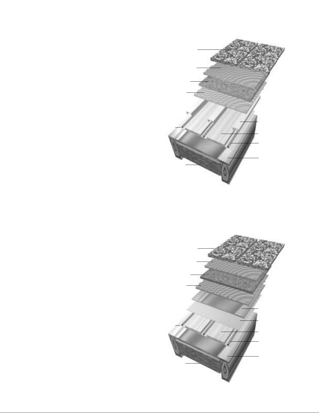
Fig. 30. Tile over SubRay system, over frame floor.
Thinset
Thinset
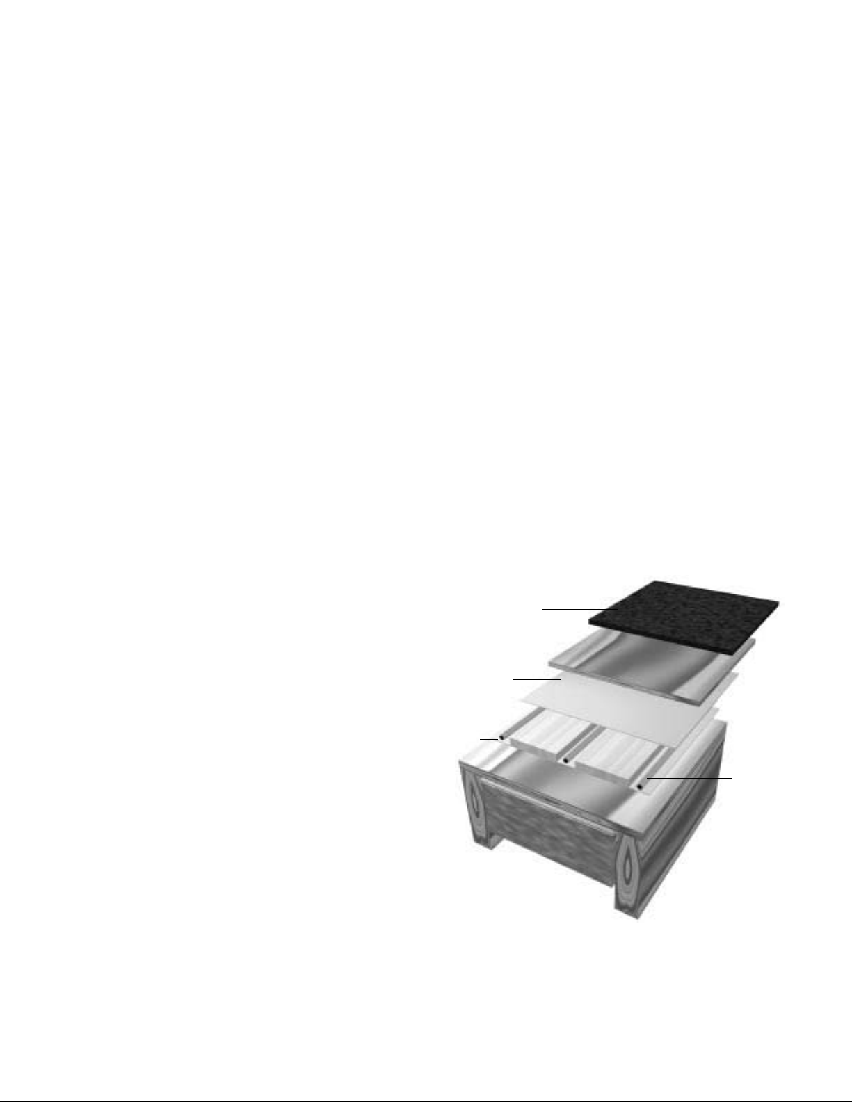
Backerboard
C-Covers
Sleepers
Radiant
Tubing
Subfloor
Tile
Fig. 31. Tile over SubRay system, over frame floor.
Thinset
Thinset
Backerboard
Second Sheet
Plywood
Aluminum
Conduction Roll
Sleepers
Radiant
Tubing
Insulation
Insulation
Subfloor
Tile
Radiant
Tape
Radiant
Tape
Page 13
SubRay Installation Manual 13
3/8" plywood. Screw the second sheet of plywood down
carefully to avoid damaging the radiant tubing. If you are
following TCA/ANSI practice of installing tile backerboard
over plywood, you’ll need to snap chalk lines on the plywood. Use these chalk lines to mark the Header Sticks
and radiant channel locations, so that you can safely
screw the cement board over the plywood (Fig. 31).
Caution: Cementious adhesives used in thinset or
mortar could cause the aluminum to surface oxidize,
breaking the bond between the aluminum and tile/stone
directly above. Use screws on 6" to 8" centers to
mechanically fasten the overlay sheets to the subfloor
and SubRay materials.
The recommended fastener is a corrosion-resistant
1-1/4" No. 8 by .323" head diameter ribbed screw with
countersunk head. The screw must be long enough to
reach through the SubRay materials to the bottom of the
supporting subfloor.
Install Tile or Stone Floor.
Caution: Always cover the aluminum conduction
sheet with cement board or plywood before setting tile
or stone. Do not apply thinset or mortar directly to the
aluminum sheet.
Using a 1/4" notched trowel, apply a layer of latex or
acrylic modified thinset mortar (complying with ANSI
A118.4) to the surface of the cement board or plywood.
Alternatively use thickset mortar as local custom or
codes may require.
Caution: The system must always be pressurized during construction. Check the pressure gauges frequently
while you are using screws or nails near the radiant tubing. Use approved Watts Radiant field splices as needed.
Consult with thinset or mortar supplier before applying
heat. Most cementious materials will require at least 7
to 28 days to reach design strength. Premature application of heat will cause weakening of thinset and mortar.
Carpet
If properly designed, most combinations of carpet
and pad may be installed over a SubRay radiant floor.
Due to the insulating value of carpet and pad, all SubRay
installations should be designed by an authorized
Watts Radiant representative using the latest version
of RadiantWorks®, Watts Radiant’s design software.
RadiantWorks software calculates the heat loss of
each zone based on the specific building design and
local climate. The software calculates the insulating
value of the floor coverings to determine the required
radiant fluid temperature. If necessary, RadiantWorks will
tell the designer if supplemental sources of heat may be
required. In most cases the radiant system is capable of
satisfying the heat load.
After laying out the SubRay components and installing
the radiant tubing, roll out the aluminum conduction roll.
Leave a 1/2" space between each roll so that the flooring contractor can see where the radiant channels are
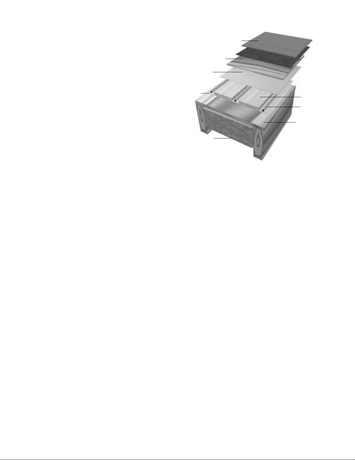
located. Screw or nail a minimum of 3/8" plywood, or
equivalent structural subflooring product, over the
SubRay components. Observe care near the Header
Sticks (see Fig. 32).
Always maintain a minimum 3" perimeter strip around
the room. This perimeter strip should not have any radiant tubing installed in it, unless the tubing is protected
against nails and carpet tack strips. If any tubing runs
from one room to another, the threshold area should
have nail guards installed to protect the tubing against
tack strips.
Caution: The system must always be pressurized
during construction. Check the pressure gauges on
your manifold test kit frequently anytime you are using
screws or nails near the radiant tubing, and for at least
24 hours afterward. Use approved Watts Radiant field
splices if the tubing is damaged.
According to industry guidelines, the radiant system
should be designed so that the surface of the carpet
does not exceed 85°F.
Advice about carpet installation is available at
the Carpet and Rug Institute in Dalton, Georgia. Call
706-428-2106 or contact the Institute at www.carpetrug.com.
Fig. 32. Carpet over SubRay system, over frame floor.
Plywood
Sleepers
Aluminum
Conduction
Roll
Radiant
Tubing
Subfloor
Insulation
Carpet
Radiant
Tape
Page 14
14 SubRay Installation Manual
Pergo®Laminate
Installation Requirements. Pergo floors can be in-
stalled over a SubRay system, as long as the following
Pergo requirements are observed. All SubRay installations should be designed by an authorized Watts
Radiant representative using the latest version of
RadiantWorks, Watts Radiant’s design software.
Preparation of Slab. Secure Sleepers and Header
Sticks to the underlying slab on 8" centers. Concrete
nails may spall some concrete, and cause rocking. If so,
use concrete screws or bolts (see Appendix A). We
recommend you predrill the Sleepers before drilling into
the concrete. The slab must have a vapor barrier
installed underneath it to prevent ground moisture from
coming up into the floor. If the slab is less than 6
months old, or contains residual moisture, it must first
be aged or heated to drive out the moisture. Tape down
a 2' x 2' square of plastic over a section of the slab and
wait 24 hours. If there is no moisture present on the
plastic sheet after this test, the concrete is suitably dry
for the finish flooring to be installed over it. If in doubt
as to moisture content of the slab, or if installing over an
existing older slab, you must install a thick (eight mil or
better) vapor over the slab. Overlap and tape the edges
of the barrier to prevent residual concrete moisture from
damaging the flooring.
The slab beneath must be insulated according to local
code and practices. In a retrofit of an existing slab, it
may not be possible to insulate the slab. See your Watts
Radiant representative for additional design and installation concepts if you cannot insulate the slab. Always consult with your Watts Radiant representative for a design
analysis when installing over an existing slab.
Preparation of Subfloor. Secure Sleepers and Header
Sticks to the underlying subfloor on 6" to 8" centers.
Preferentially use screws. Do not install a vapor barrier
over a subfloor if the space below is unconditioned, as
this could trap moisture in the floor. Always insulate
under the subfloor in accordance with local codes. If in
doubt as to the recommended insulation, consult with
Watts Radiant for design assistance.
RadiantWorks software calculates the heat loss of
each zone based on the specific building design and
local climate. The software calculates the insulating
value of the floor coverings to determine the required
radiant fluid temperature. If necessary, RadiantWorks will
tell the designer if supplemental sources of heat may be
required. In most cases the radiant system is capable of
satisfying the heat load.
After laying out the SubRay components and installing
the radiant tubing; roll out the aluminum conduction roll.
Leave a 1/2" space between each roll so that the flooring contractor can see where the radiant channels are
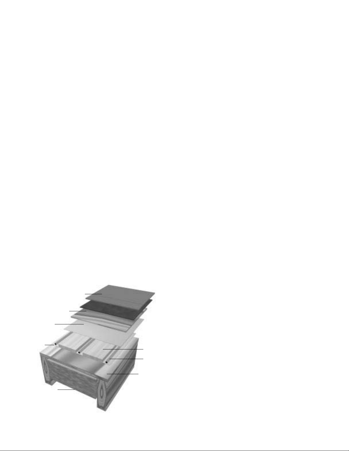
located. Screw or nail a minimum of 1/2" plywood over
the SubRay components. Observe care near the Header
Sticks.
Always maintain a minimum 3" perimeter strip around
the room. This perimeter strip should not have any radiant tubing installed in it unless the tubing is protected
against trim nails/staples and possible future carpet
tack strips. If any tubing runs from one room to another,
the threshold area should have nail guards installed to
protect the tubing against possible future tack strips.
Caution: The system must always be pressurized
during construction. Check the pressure gauges on
your manifold test kit frequently anytime you are using
screws or nails near the radiant tubing, and for at least
24 hours afterward. Use approved Watts Radiant field
splices if the tubing is damaged.
According to Pergo guidelines, the radiant system
should be designed so that the surface of the Pergo
flooring does not exceed 84°F. A Watts Radiant
DualTemp thermostat is available with this floor limit
feature.
Advice about Pergo specifications and installation
instructions is available at www.pergo.com.
Wilsonart
®
Installation Requirements. Wilsonart floors can be
installed over a SubRay system, as long as the Wilsonart
requirements are observed. All SubRay installation
should be designed by an authorized Watts Radiant
representative using the latest version of RadiantWorks,
Watts Radiant’s design software.
Preparation of Slab. Secure Sleepers and Header
Sticks to the underlying slab on 8" centers. Concrete
nails may spall some concrete, and cause rocking. If so,
Fig. 33. Pergo over SubRay system, over frame floor.
Sleepers
Radiant
Tubing
Pergo
1/2" Plywood
Aluminum
Conduction
Roll
Insulation
Subfloor
Radiant
Tape
Page 15
SubRay Installation Manual 15
use concrete screws or bolts (see Appendix A). We
recommend you predrill the Sleepers before drilling into
the concrete. The slab must have a vapor barrier
installed underneath it to prevent ground moisture from
coming up into the floor. If the slab is less than 6
months old, or contains residual moisture, it must first
be aged or heated to drive out the moisture. Tape down
a 2' x 2' square of plastic over a section of the slab and
wait 24 hours. If there is no moisture present on the
plastic sheet after this test, the concrete is suitably dry
for the finish flooring to be installed over it. If in doubt
as to moisture content of the slab, or if installing over
an existing older slab, you must install a thick (8 mil or
better) vapor over the slab. Overlap and tape the edges
of the barrier to prevent residual concrete moisture from
damaging the flooring.
The slab beneath must be insulated according to local
code and practices. In a retrofit of an existing slab, it
may not be possible to insulate the slab. See your Watts
Radiant representative for additional design and installation concepts if you cannot insulate the slab. Always
consult with your Watts Radiant representative for a
design analysis when installing over an existing slab.
Preparation of Subfloor. Secure Sleepers and Header
Sticks to the underlying subfloor on 6" to 8" centers.
Preferentially use screws. Do not install a vapor barrier
over a subfloor if the space below is unconditioned, as
this could trap moisture in the floor. Always insulate
under the subfloor in accordance with local codes. If in
doubt as to the recommended insulation, consult with
Watts Radiant for design assistance.
Fig. 34. Wilsonart over SubRay system, over frame floor.
Sleepers
Radiant
Tubing
Wilsonart
1/2" Plywood
Aluminum
Conduction
Roll
Insulation
Subfloor
Radiant
Tape
RadiantWorks software calculates the heat loss of
each zone based on the specific building design and
local climate. The software calculates the insulating
value of the floor coverings to determine the required
radiant fluid temperature. If necessary, RadiantWorks will
tell the designer if supplemental sources of heat may be
required. In most cases the radiant system is capable of
satisfying the heat load.
After laying out the SubRay components and installing
the radiant tubing; roll out the aluminum conduction roll.
Leave a 1/2" space between each sheet so that the
flooring contractor can see where the radiant channels
are located. Screw or nail a minimum of 1/4" plywood
over the SubRay components. Observe care near the
Header Sticks.
Always maintain a minimum 3" perimeter strip around
the room. This perimeter strip should not have any radiant tubing installed in it, unless the tubing is protected
against trim nails/staples, and possible future carpet
tack strips. If any tubing runs from one room to another,
the threshold area should have nail guards installed to
protect the tubing against possible future tack strips.
Caution: The system must always be pressurized
during construction. Check the pressure gauges on
your manifold test kit frequently anytime you are using
screws or nails near the radiant tubing, and for at least
24 hours afterward. Use approved Watts Radiant field
splices if the tubing is damaged.
According to Wilsonart guidelines, the radiant
system should be installed so that the surface of the
Wilsonart flooring does not exceed 84°F. A Watts
Radiant DualTemp thermostat is available with this
floor limit feature.
Advice about Wilsonart specifications and installation
instructions is available at www.wilsonart.com, or call
1-800-710-8846.
Other Flooring Options
Other flooring options may be heated with a SubRay
system. Consult with Watts Radiant and the flooring
manufacturer for written application instructions before
proceeding. Some vinyl floors are very temperature
sensitive and may fade when exposed to normal floor
warming conditions.
Watts Radiant can make no representations regarding
color stability of all vinyl floors. We suggest you consult
with the flooring manufacturer to verify that their product
is temperature stable.
The use of a Watts Radiant DualTemp thermostat provides for a safe and easy way to limit the floor surface
temperature. Simply dial in the maximum floor temperature you want and this control will not permit your floor
to rise above the limit you have programmed.
Page 16
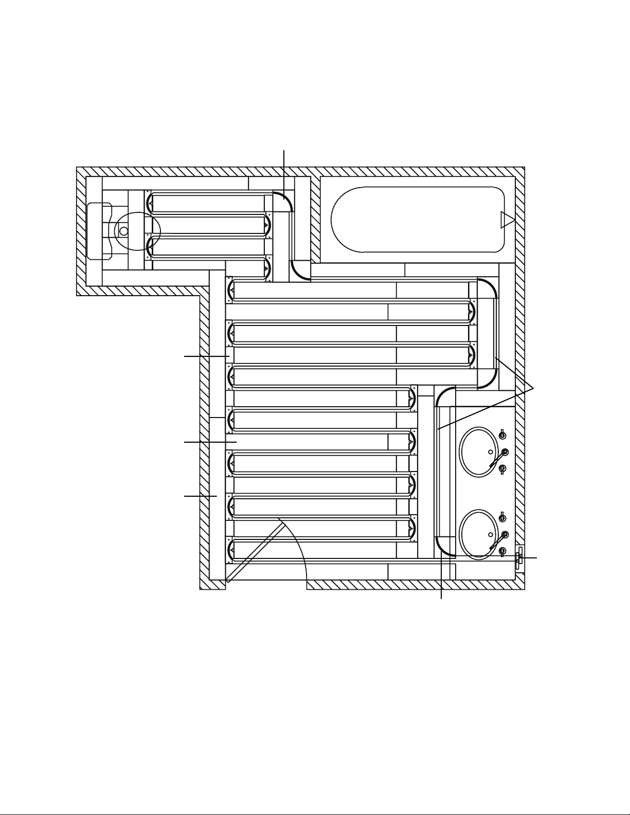
Fig. 35. SubRay system alternate layout: bathroom
16 SubRay Installation Manual
Header Stick
C-Covers
(optional)
Supply/Return
Manifolds
Place tubing as close as
possible to face of cabinet.
Corner Sweep
Sleepers
Perimeter Strip
Bath Layout
1 circuit of tubing, 130' long
Page 17
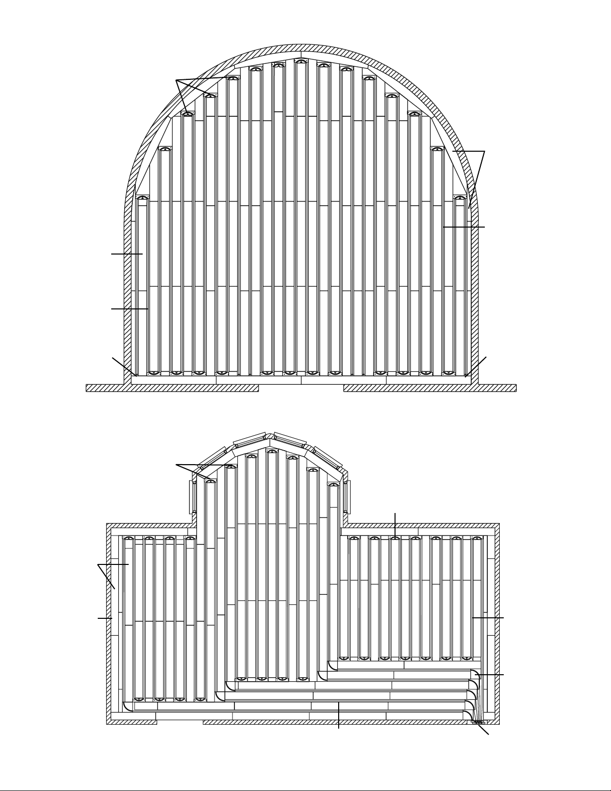
SubRay Installation Manual 17
Fig. 36. SubRay layout: room with circular wall.
Fig. 37. SubRay layout: room with bay window.
Sleeper
Header Stick
(cut to accommodate
curve of the wall)
C-Cover
(optional)
Sleepers
Perimeter Strip
Tubing enters zone
from manifold
below floor
Tubing returns to
manifold below
floor
C-Cover
(optional)
Perimeter Strip
C-Cover
(optional)
Header Stick
Corner Sweep
Header Stick
(cut to accommodate
curve of the wall)
C-Cover (optional)
Supply/Return
Manifolds
Circular Wall Layout
3 circuits of tubing, 150' long
Bay Window Layout
3 circuits of tubing, 160' long
Page 18
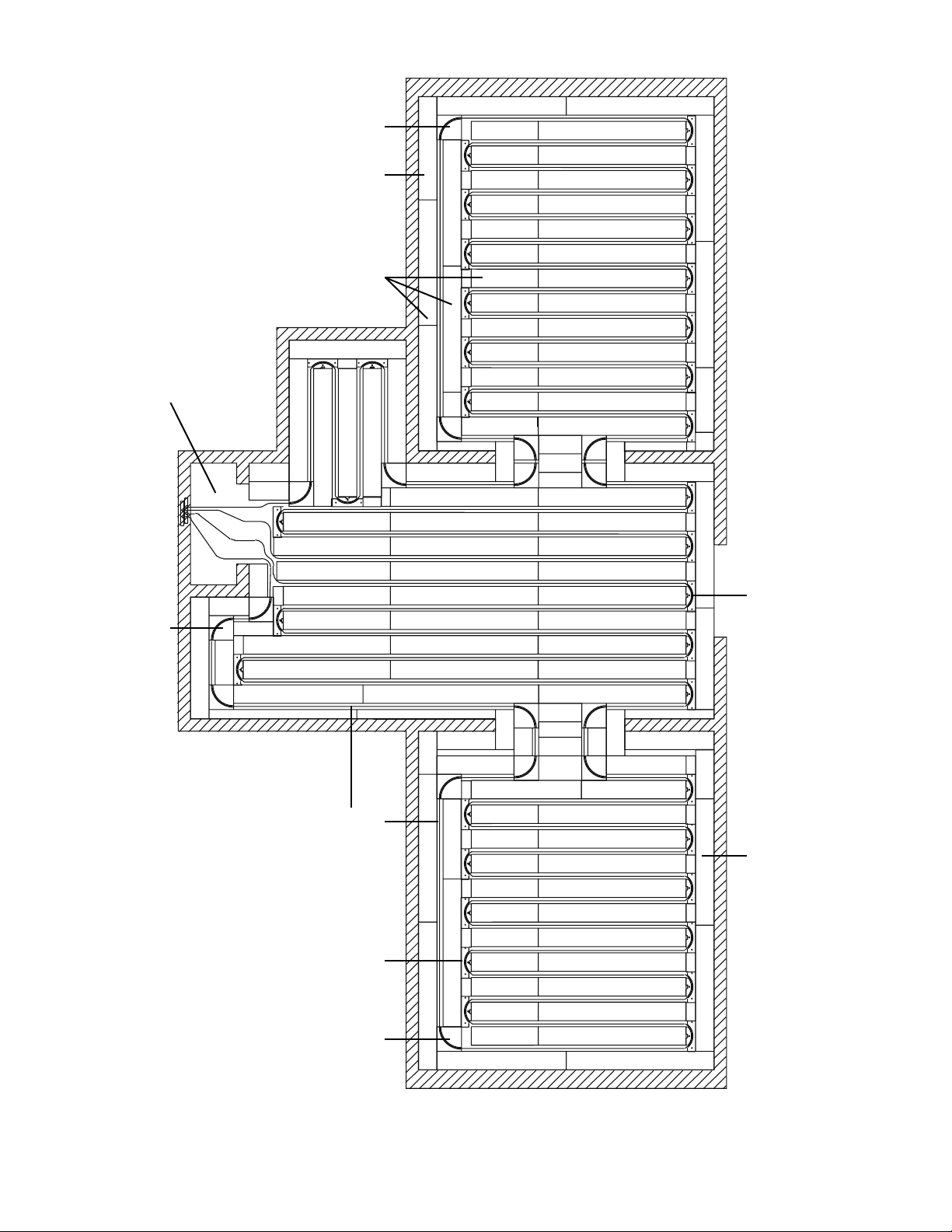
18 SubRay Installation Manual
Fig. 38. SubRay layout: three rooms with central manifold.
Supply/Return
Manifolds
Fill in this area with
scrap Sleeper cut-offs.
Corner Sweep
Corner Sweep
Sleepers
C-Covers
(optional)
Header Sticks
Perimeter Strip
Corner Sweep
Header Sticks
Perimeter Strip
Three-room Layout
2 circuits of tubing, 160' long
Page 19
SubRay Installation Manual 19
Attaching the SubRay Components to Concrete
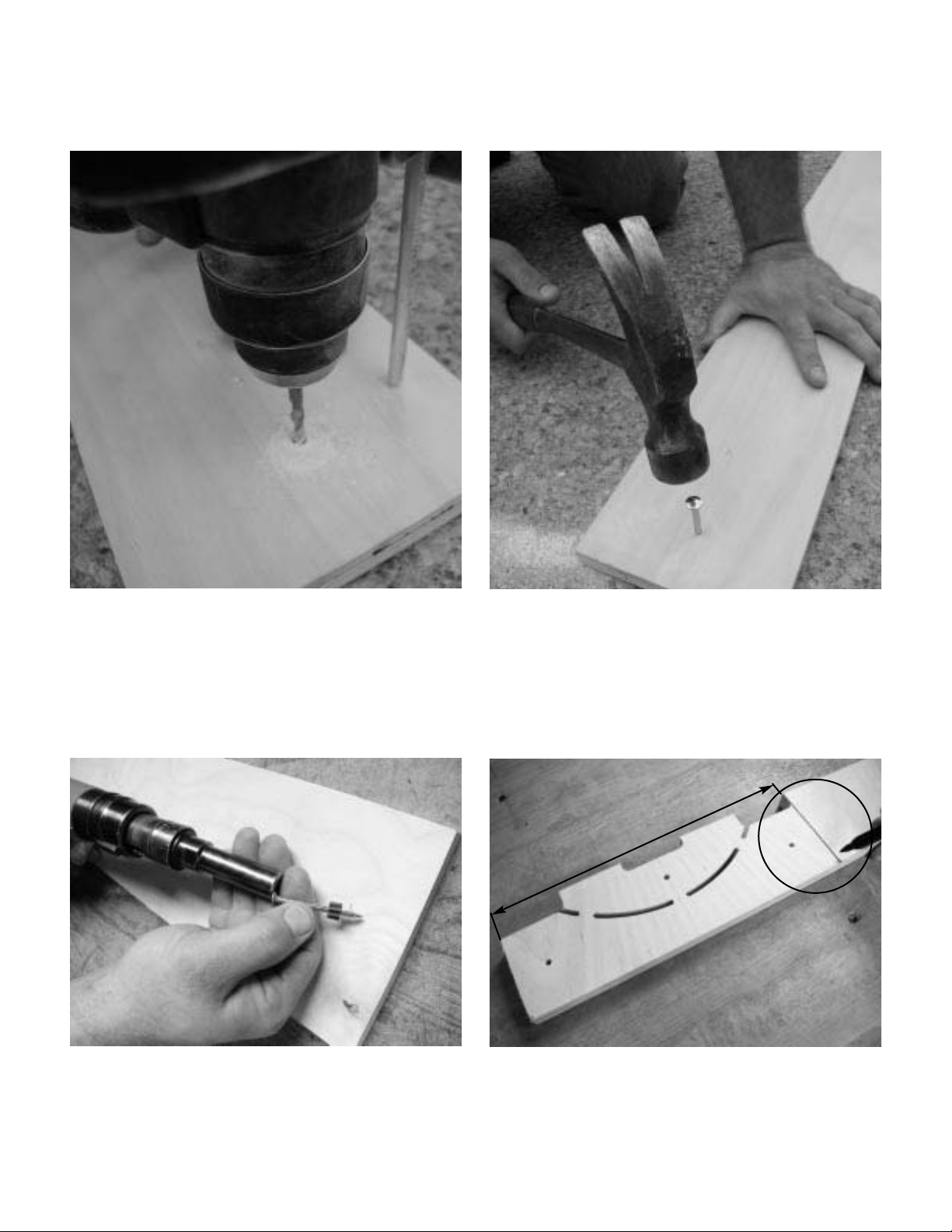
Fig. 39. If you need to secure the Header Sticks or
Sleepers to a concrete slab, first lay out your components so you have a very good idea of where they will
be permanently fastened. Use a hammer drill with a
3/16" carbide tipped masonry bit to drill a 1-3/4" deep
hole through the Sleeper and into the concrete.
Fig. 40. Place a 1-1/2" Powers Mush Head Spike (or
equivalent) in the hole and use a hammer to drive the
spike so the head is flush or below the surface of the
wood. Locate Spikes as needed along the Sleepers and
Header Sticks. The Spikes are permanent and cannot
be removed without destroying the wood, so plan your
work carefully.
Fig. 41. You can also secure SubRay Sleepers and
Header Sticks to a concrete slab using a powder
actuated nailer. Be sure to use facial and ear protection
when using this device.
Fig. 42. When you must trim a SubRay Header Stick,
cut it along line indicated by the circle to preserve the
2" radiant channel. For more detailed information
on properly cutting Header Sticks, see page 23.
Appendix A
10"
Page 20
20 SubRay Installation Manual
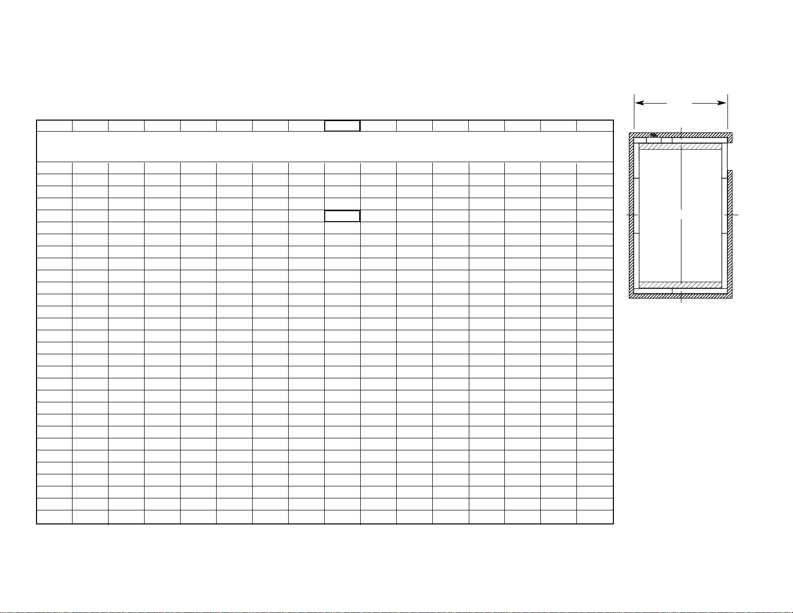
3" 3.5" 4" 4.5" 5" 5.5" 6" 6.5" 7" 7.5" 8" 8.5" 9" 9.5" 10" 10.5"
48 49 50 51 52 53 54 55 56 57 58 59 60 61 62 63
64 65 66 67 68 69 70 71 72 73 74 75 76 77 78 79
80 81 82 83 84 85 86 87 88 89 90 91 92 93 94 95
96 97 98 99 100 101 102 103 104 105 106 107 108 109 110 111
112 113 114 115 116 117 118 119 120 121 122 123 124 125 126 127
128 129 130 131 132 133 134 135 136 137 138 139 140 141 142 143
144 145 146 147 148 149 150 151 152 153 154 155 156 157 158 159
160 161 162 163 164 165 166 167 168 169 170 171 172 173 174 175
176 177 178 179 180 181 182 183 184 185 186 187 188 189 190 191
192 193 194 195 196 197 198 199 200 201 202 203 204 205 206 207
208 209 210 211 212 213 214 215 216 217 218 219 220 221 222 223
224 225 226 227 228 229 230 231 232 233 234 235 236 237 238 239
240 241 242 243 244 245 246 247 248 249 250 251 252 253 254 255
256 257 258 259 260 261 262 263 264 265 266 267 268 269 270 271
272 273 274 275 276 277 278 279 280 281 282 283 284 285 286 287
288 289 290 291 292 293 294 295 296 297 298 299 300 301 302 303
304 305 306 307 308 309 310 311 312 313 314 315 316 317 318 319
320 321 322 323 324 325 326 327 328 329 330 331 332 333 334 335
336 337 338 339 340 341 342 343 344 345 346 347 348 349 350 351
352 353 354 355 356 357 358 359 360 361 362 363 364 365 366 367
368 369 370 371 372 373 374 375 376 377 378 379 380 381 382 383
384 385 386 387 388 389 390 391 392 393 394 395 396 397 398 399
400 401 402 403 404 405 406 407 408 409 410 411 412 413 414 415
416 417 418 419 420 421 422 423 424 425 426 427 428 429 430 431
432 433 434 435 436 437 438 439 440 441 442 443 444 445 446 447
448 449 450 451 452 453 454 455 456 457 458 459 460 461 462 463
464 465 466 467 468 469 470 471 472 473 474 475 476 477 478 479
480 481 482 483 484 485 486 487 488 489 490 491 492 493 494 495
496 497 498 499 500 501 502 503 504 505 506 507 508 509 510 511
512 513 514 515 516 517 518 519 520 521 522 523 524 525 526 527
Rip Perimeter Strips to this width for two sides of the room, according to room width.
Width of Span Wall (inches)
120"
Use standard 6" Perimeter
Strips behind Header
Sticks. See chart for other
Perimeter Strip widths.
Example: When width of
room equals 120" (see
chart at left for 120"
width), look at top of chart
to see Perimeter Strip width
(7") for non-Header Stick
walls.
Fig. 43. How to center Header Sticks.
Appendix B
Selecting Perimeter Strip Widths to Center Header Sticks to Room
6" Perimeter Strips
7" Perimeter Strips
7" Perimeter Strips
6" Perimeter Strips
Header Sticks
Page 21

SubRay Installation Manual 21
Appendix C
SubRay Materials Estimating Guide
Introduction: Before using this quick SubRay material estimating sheet,
read the SubRay design manual. Actual quantities of Header Sticks
and Sweeps may vary, especially for complex or irregular rooms. The
amount of Sleepers, Tape, Grippers, and Aluminum Rolls relates directly
to room size.
The SubRay 862 system uses tubing on 8" centers, so 1' of tubing will
heat .67 sq. ft. of floor. Typical lengths for 3/8" tubing are 200’ and for
1/2" tubing 300'.
Fill in the blanks to calculate your material requirements. See the Watts
Radiant website for a simple automated SubRay quoting system.
If using 3/8" RadiantPEX order 15 mm (coded red) wood parts and
channels. If you are using 1/2" RadiantPEX or 3/8" Onix order 18 mm
(coded blue) wood parts and channels.
Room Area
Calculate the room area (length x width) in square feet (sq. ft.) and
enter below.
L ________ x W ________ = ________ sq. ft.
Example: 20' x 40' room = 800 sq. ft.
Radiant Tubing
Divide room area by .67 to get feet of tubing.
_________ sq. ft./.67 = ________ total feet of radiant tubing.
Example: 800 sq. ft./.67 = 1194 ft. of tubing.
Radiant Circuits
Divide feet of radiant tubing by typical circuit length.
We suggest 200' for 3/8" tubing, and 300' for 1/2" tubing.
Round the result up to the next largest whole number.
________ ft. of tubing/200 = _______ circuits of 3/8" tubing.
________ ft. of tubing/300 = _______ circuits of 1/2" tubing.
Example: 1194 ft. tubing/200 = 5.97 circuits of 3/8" tubing.
Round this up to 6 circuits, each averaging about 199 ft.
Figuring Notes:
Page 22

22 SubRay Installation Manual
Appendix C (continued)
SubRay Materials Estimating Guide
Header Sticks
Add the lengths of the two opposing walls along which the Header Sticks
will be installed. Normally, these are the two short walls in the room,
but the finished orientation of a hardwood floor may dictate otherwise.
See page 5 for example.
_______ Wall A + _______ Wall B = ________ Total Header Wall Length.
Example: 20' + 20' = 40' of Header Wall Length (HWL).
Divide this total by 3.5 to get the number of Header Sticks you’ll need.
Round up to the next largest number.
________ (HWL)/3.5 = ________ Number of Header Sticks.
Example: 40/3.5 = 11.4. Order 12 Header Sticks.
Sleepers
Take the room area and divide by 3.3 to get the number of Sleepers.
________ (area)/3.3 = ________ Number of Sleepers.
Example: 800 sq. ft./3.3 = 242 Sleepers
Corner Sweeps (not needed for Onix installations)
Multiply number of radiant circuits in room by four for rectangular rooms.
Multiply number of radiant circuits in room by twelve for complex rooms.
________ (circuits) x ________ = ________ Sweeps Needed.
Example: A square room with 6 circuits will need 6 x 4 = 24
Corner Sweeps.
Rolls of Radiant Tape
Divide room area by 240 and round up to next largest number.
_______ (area)/240 = _______ Number of Radiant Tape Rolls.
Example: 800/240 = 3.33. Order 4 Radiant Tape Rolls.
Figuring Notes:
Page 23
SubRay Installation Manual 23
Appendix C (continued)
SubRay Materials Estimating Guide
Grippers (not needed for Onix installations)
Multiply the number of radiant circuits by two.
______ Radiant Circuits x 2 = ______ number of Grippers.
Example: 6 circuits x 2 = 12. Order 12 Grippers.
Aluminum Conduction Rolls
Divide room area by 70 and round up to next largest number.
_______ room area/70 = ______ Number of Aluminum Rolls.
Example: 800/70 = 11.4. Order 12 Rolls of Aluminum.
C-Covers
For most hardwood floors order enough C-Covers to run the length
of the room.
Divide room length by 4 to get number of C-Covers.
______ room length/4 = ______ number of C-Covers.
Example: The room is 40' long. 40/4 = 10. Order 10 C-Covers.
Note: Many projects may not need C-Covers. See Manual to see
if you need them.
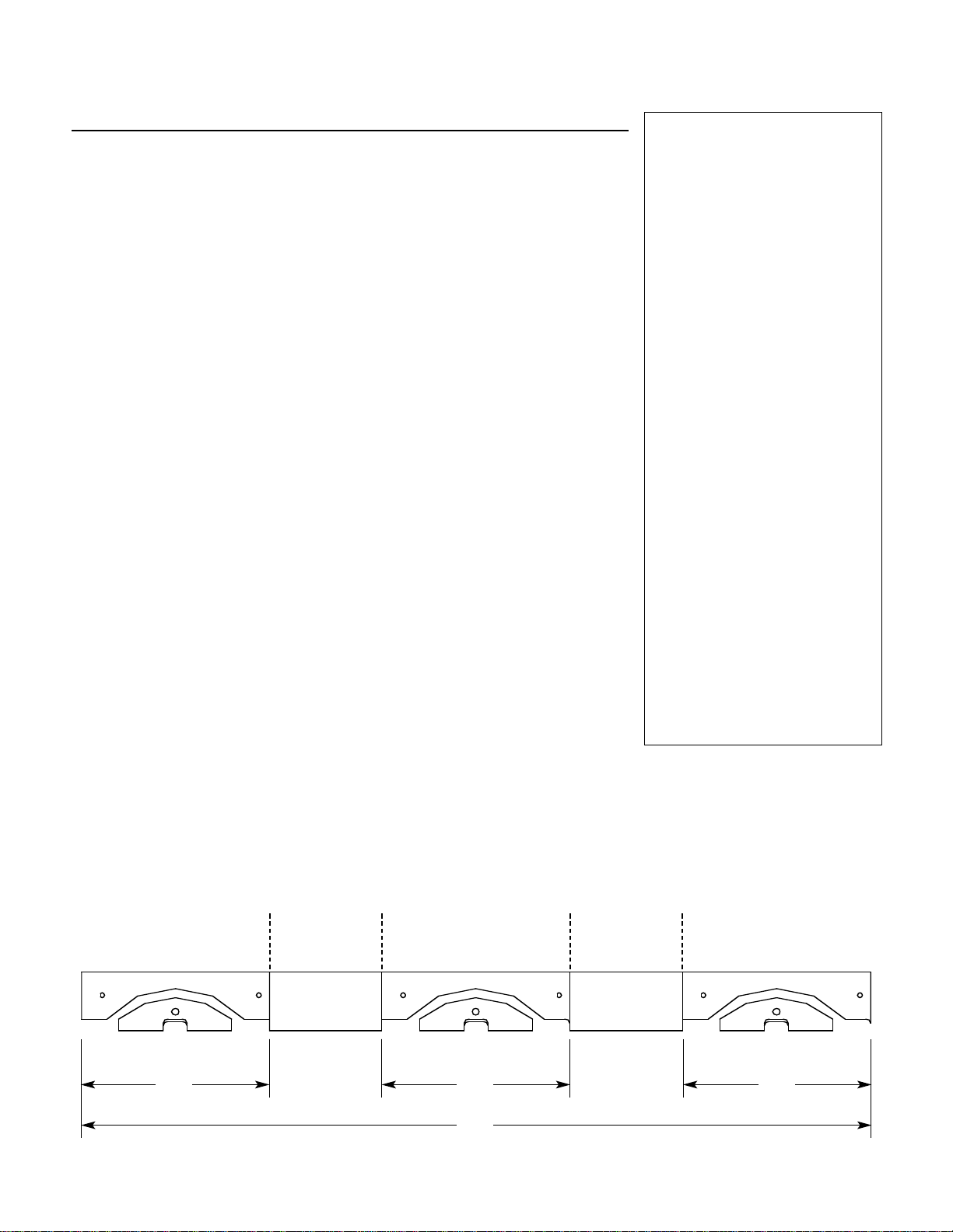
Header Stick cutting detail:
Figuring Notes:
42"
10"10"10"
CUT
CUT
CUT
CUT
Page 24
Proud Members Of:
Charter Member:
4500 E. Progress Place
Springfield, MO 65803-8816
417-864-6108
Radiant Panel Association
417-864-8161 f a x
800-276-2419 (u s a and c a n a d a )
www.wattsradiant.com
© Copyright 2004-2008 Watts Radiant, Inc. SubRay Installation Manual 4.0 LIT#SR862MAN0308 Effective 03/01/2008
 Loading...