

Page 1
insulated piping systems
installation manual
Page 2
2
insulated piping system
Table of Contents
Description . . . . . . . . . . . . . . 2
Specifications ............. 3
Warnings ............... 3
Transportation . . . . . . . . . . . . 4
Connections . . . . . . . . . . . . . 5
Utility Trenches ............ 6
Wall Penetrations . . . . . . . . . . 8
Intersections . . . . . . . . . . . . 11
Inspection Chamber . . . . . . . 15
Repairs ................ 19
Appendix
A - System Design . . . . . . . . 20
B - Pressure Drops ........ 25
Description
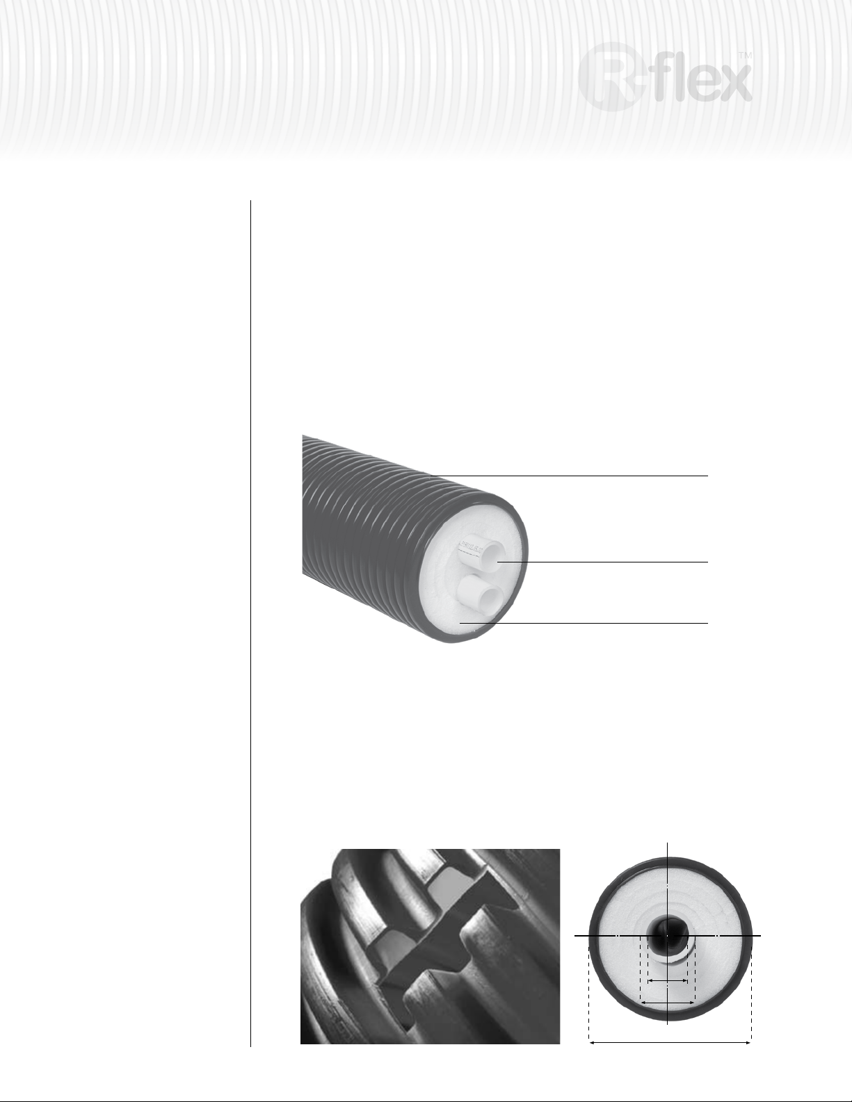
Well insulated piping systems equate to energy savings. Watts Radiant’s R-flex™ series is a
pre-insulated piping system composed of a thermal insulated jacket surrounding the carrier pipe(s).
Each foot of R-flex is protected by a double wall high density polyethylene outer jacket.
R-flex is an SDR-11 PEX fluid transfer piping system suitable for use in heating or cooling applications.
Each foot of R-flex is protected with an EVOH oxygen diffusion layer. Low weight and superior flexibility
means R-flex can be installed easily and rapidly, even over obstacles or around corners.
R-flex is available with either a single or double carrier pipe in a wide variety of sizes, all offering
superior insulation properties. The insulating material consists of microcellular, cross-linked polyethylene
foam. The closed-cell structure of the foam provides excellent insulation values, ensures minimal water
absorption, and is CFC free.
Corrugated twin wall
outer jacket (PE-HD)
Carrier Pipe
(cross-linked barrier PEX)
Insulation
(cross-linked PE foam)
C - Pressure Test Logs . . . . . 30
D - Installation Times ....... 31
Carrier pipes in Dual R-flex are marked with a single dash line and a double
dashed line to provide easy identification at transition points.
The outer shell of R-flex is constructed of double-wall, high density corrugated polyethylene. A durable,
watertight seal is provided between the inner and outer surface, ensuring that moisture ingress is
prevented in the event that the outer casing is damaged. This unique combination of inner and outer
layers also allows the corrugated design of the outer shell to bend easier, providing greater flexibility.
PEX ID
PEX OD
Jacket OD
Page 3
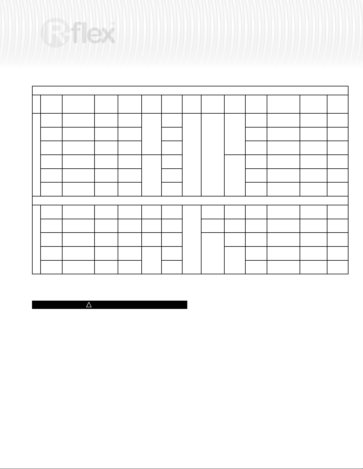
Specifications (conforms to DIN 16892, SDR-11)
3
insulated piping system
Order # Description
81012929 160/40 R-flex
81012886 160/50 R-flex
81012887 160/63 R-flex
Single
81012889 200/75 R-flex
81012890 200/90 R-flex
81012891 200/110 R-flex
81012879 125/2x1 R-flex*
81012880 125/2x32 R-flex
81012882 160/2x40 R-flex
Dual
81012884 200/2x50 R-flex
81012885 200/2x63 R-flex
PEX
ID
32.6 mm
(1.28")
40.8 mm
(1.61")
51.6 mm
(2.03")
61.4 mm
(2.42")
73.6 mm
(2.90")
90.0 mm
(3.55")
0.863"
(21.92 mm)
26.2 mm
(1.03")
32.6 mm
(1.28")
40.8 mm
(1.61")
51.6 mm
(2.03")
PEX
OD
40 mm
(1.57")
50.0 mm
(1.97")
63.0 mm
(2.48")
75.0 mm
(2.95")
90.0 mm
(3.54")
110.0 mm
(4.33")
1.125"
(28.58 mm)
32.0 mm
(1.26")
40.0 mm
(1.57")
50.0 mm
(1.97")
63.0 mm
(2.48")
JacketODBend
Radius
350 mm
(13.8")
160 mm
(6.30")
200 mm
(7.90")
4.90"
(125 mm)
125 mm
(4.90")
160 mm
(6.30”)
200 mm
(7.90")
450 mm
(17.80")
550 mm
(21.7”)
800 mm
(31.5")
1100 mm
(43.4”)
1200 mm
(47.3")
11.80"
(300 mm)
300 mm
(11.80")
600 mm
(23.70")
800 mm
(31.50")
1200 mm
(47.30")
Coil
Length
100 m**
(328 ft)
100 m**
(328 ft)
Coil
Diameter
2300 mm
(90.6")
82.70"
(2100 m
2100 mm
(82.70")
2300 mm
(90.60")
Coil
Height
850 mm
(33.50")
1400 mm
(55.20")
27.60"
(700 mm)
700 mm
(27.60")
850 mm
(33.50")
1400 mm
(55.20")
Coil
Weight
232 kg
(512 lbs)
248 kg
(547 lbs)
278 kg
(613 lbs)
416 kg
(917 lbs)
473 kg
(1,043 lbs)
564 kg
(1,244 lbs)
358 lbs
(162 kg)
182 kg
(402 lbs)
263 kg
(580 lbs)
403 kg
(889 lbs)
464 kg
(1,023 lbs)
Fluid Cap.
/ 100m (328ft)
83.00 L
(21.93 gal)
131.31 L
(34.69 gal)
208.76 L
(55.15 gal)
296.67 L
(78.37 gal)
426.02 L
(112.55 gal)
638.41 L
(168.65 gal)
19.94 gal
(75.46 L)
107.48 L
(28.40 gal)
166.00 L
(43.86 gal)
262.62 L
(69.38 gal)
417.52 L
(110.30 gal)
Insulation
Thickness
47.5 mm
(1.88")
42.5 mm
(1.68")
37.0 mm
(1.46")
52.0 mm
(2.05")
44.0 mm
(1.74")
34.0 mm
(1.33")
1.11"
(28.0 mm)
22.3 mm
(0.88")
34.0 mm
(1.34")
46.0 mm
(1.81")
33.0 mm
(1.30")
Casing
R-Value
6.79
6.07
5.27
7.4
6.28
4.84
4.01
3.18
4.84
6.57
4.69
Pex pipe is certied to ASTM F876, SDR-9 dimensions.
*
Custom lengths are available upon request. Contact distributor for details.
**
!
WARNINGS
General Handling & Storage
If R-flex connections must be made in temperatures lower than 30°F, caution
must be taken to allow the tubing to form a proper seal against the barb. Apply
the connection slowly to ensure the PEX material conforms to the barb.
In order to prevent property damage, serious injury and/or death...
1. Do not allow the fluid temperature to exceed:
• 200°F at 80psi
• 180°F at 100psi
• 73.4°F at 160psi
2. Do not allow the inner PEX tubing to be exposed to sunlight, or direct UV
exposure for more than 30 days maximum. Outer casing of R-flex protects
the inner PEX tubing from UV exposure.
3. Do not allow the tubing to come in contact with any of the following:
– Petroleum based products
– Pipe sealants
– Firewall sealants (except those approved to be used with PEX)
– Kerosene
– Gasoline
– Fuel oils
– Cutting oils
– Asphalt
– Contaminated soils or building materials.
4. Do not use if the tubing has visible gouges, cuts, cracks, abrasions, signs of
physical damage, or other defects.
5. Do not use in swimming pools or other systems that use high levels
of chlorine.
6. Do not kink. If kinking occurs, use a repair coupling.
7. Do not expose tubing to rough terrain that may cause punctures, cuts, or
other damage.
8. Do not use tubing to transfer natural gas or any unapproved substances.
9. Do not use Crimp, Cinch, or Compression connections designed for
RadiantPEX or RadiantPEX+ with metric size R-flex tubing.
Page 4
4
insulated piping system
General Installation Cautions
1. When installing R-flex, use a serpentine pattern to account for expansion
and contraction. Failure to do so may result in damage to connections.
2. Do not install directly to a heat source. A metallic adapter, minimum 18" in
length, must be used between the heat source and tubing.
3. Do not support fixtures directly from the tubing, such as hose bibs or
shut-off valves.
4. Protect the tubing via sleeves where it transitions through a concrete slab,
concrete wall or other framing material.
5. Do not use this manual to install Watts Radiant Onix™, RadiantPEX™,
RadiantPEX
™
+
, or RadiantPEX-AL™.
Transport and Storage
R-ex pipelines are supplied in coils with a maximum length of 328 ft (100
meters). Pipe ends are factory sealed with protective end caps to prevent dirt
and debris from entering the tubing.
In storage, care must be taken to ensure that the PEX carrier pipe is protected
from sunlight and that no undesirable deformation of the coil occurs.
Pipes must be transported and stored in such a way that sharp objects, like
stones and tree roots cannot damage them. Pipes must not be dragged along
the ground. Only nylon or textile straps should be used for fastening the
coils during transport.
Connections
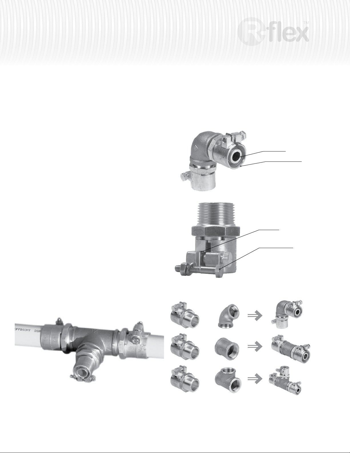
R-flex connections are specifically designed and engineered for hydronic
heating and cooling applications. They are available in PEX x NPT adapters.
Tees and elbows can be constructed with the use of an NPT tee or elbow.
R-flex Barb
Compression Collar
Steel Plate
Compression Bolt
+
+
+
Standard NPT Tees, Elbows, and Couplings are used with R-flex fittings to create a wide
range of fitting configurations.
Page 5
insulated piping system
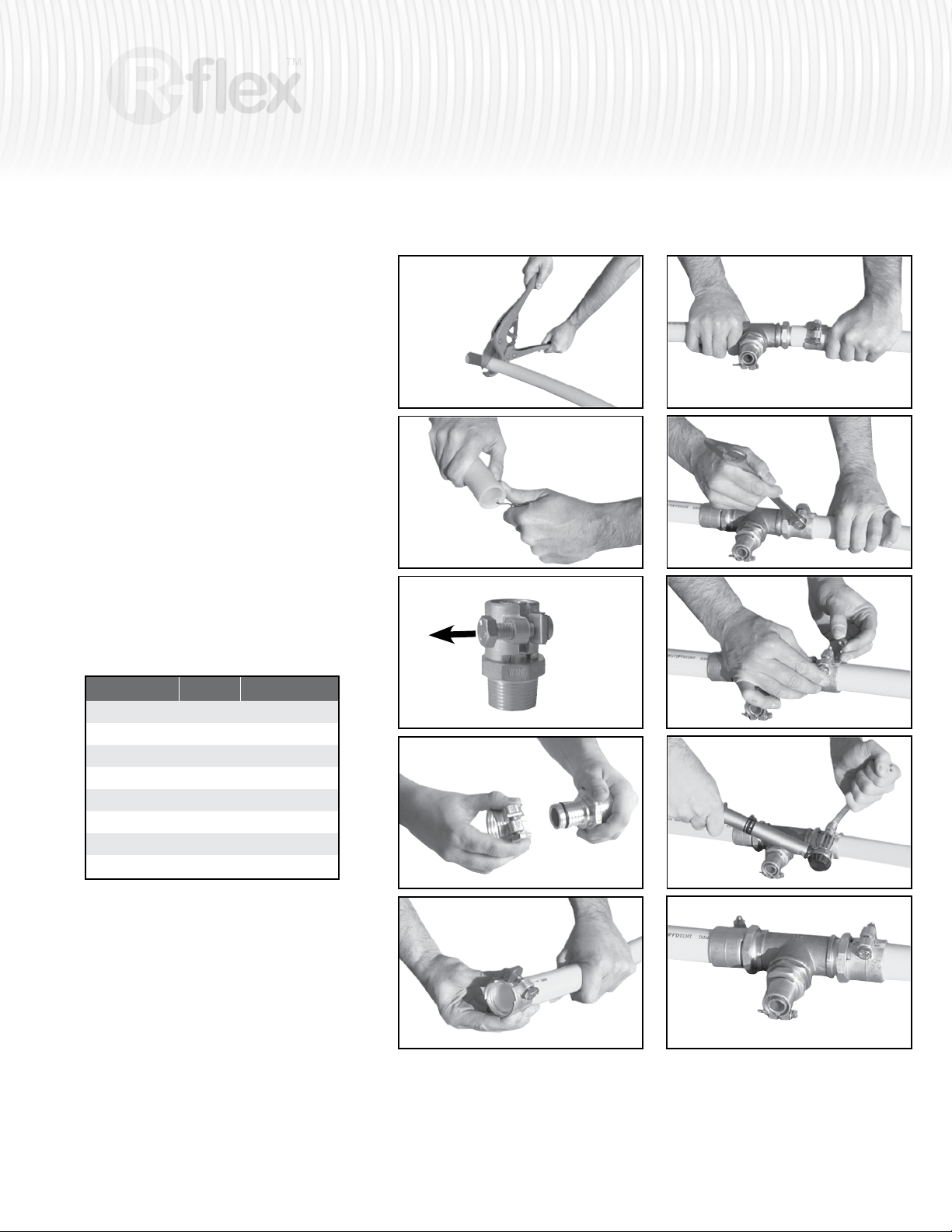
Assembly instructions
1 Cut the PEX pipe at a right angle with a pair of
PEX cutters.
2 If the tubing is cut by a saw, deburr the pipe
with an appropriate tool.
&
4 The compression fitting comes with a nut and
3
steel plate. Use these to open the compression
collar and allow the collar to slide off of the
NPT base.
5 Slide the compression collar over the pipe.
Ensure the notch on the inside of the clamping
ring is facing the fitting.
6 Push the pipe COMPLETELY over
the coupling.
1
5
6
7 Slide the clamping ring back to COMPLETELY
cover the fitting.
8 Remove the bolt and the steel plate.
&
10 Assemble the bolt, washer and nut provided
9
and tighten the compression collar to the
following torque recommendations:
R-flex Diameter Bolt Size Torque
1” (USA / Canada) M 8 8 Nm (5.9 ft-lbf)
32 mm M 8 8 Nm (5.9 ft-lbf)
40 mm M 8 10 Nm (7.38 ft-lbf)
50 mm M 10 40 Nm (29.50 ft.lbf)
63 mm M 12 70 Nm (51.63 ft-lbf)
75 mm M 12 70 Nm (51.63 ft-lbf)
90 mm M 16 110 Nm (81.13 ft-lbf)
110 mm M 16 110 Nm (81.13 ft-lbf)
Test Connections:
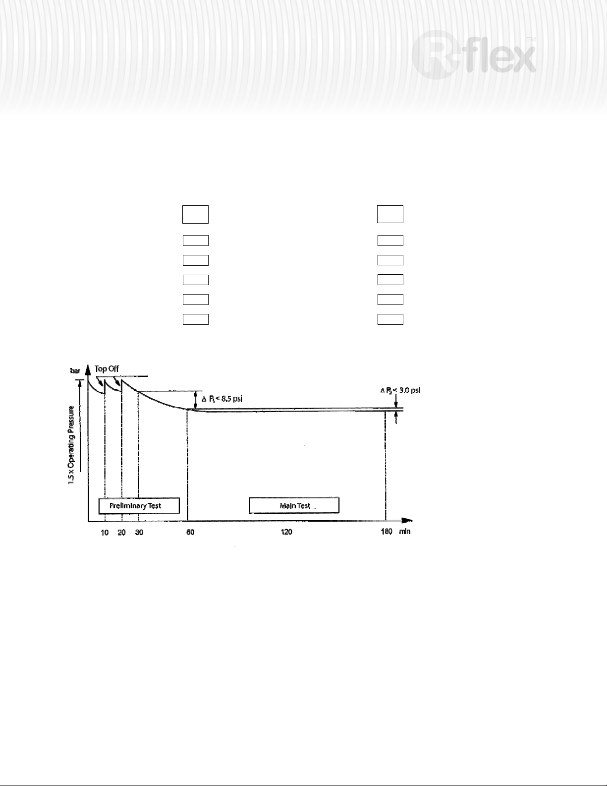
1. Preliminary test
The preliminary test involves applying a test pressure
equal to 1.5 times the admissible operating pressure.
This pressure must be regenerated twice within the space
of 30 minutes at intervals of 10 minutes. Following a test
period of another 30 minutes, the test pressure must not
have fallen by more than 9 psi. Leaks must not occur at
any points in the system being tested.
3
2
4
5
7
8
9
10
2. Main test
The main test has to be conducted immediately after the preliminary test. The test takes 2 hours. At the end
of this period, the test pressure recorded after the preliminary test must not have fallen by more than 3 psi.
Leaks must not occur at any point in the system being tested.
(See Appendix C on page 30 for time-pressure curve of test method and log for test results)
Page 6
6
insulated piping system
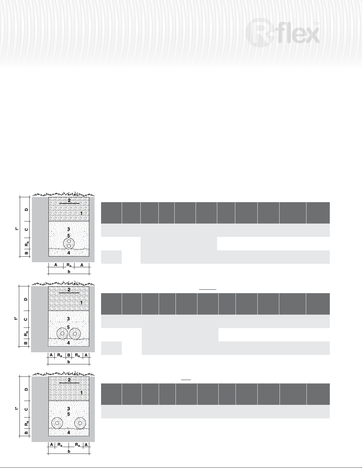
Utility Trench Profile
Trenches 4ft (120 cm) or less can be dug with vertical walls. If the trench is
to be deeper than 4 ft (120 cm), a V-shaped trench should be dug to prevent
accidental wall-collapse.
Excavation work must be carried out in the approved manner, according to the
rules and regulations of local authorities.
The depth of the trench must be in accordance with the guidelines relating to
the laying of R-flex.
1 Backfill
2 Route warning tape - to indicate buried pipe underfoot
3 Sand fill
4 Sandbed
5 R-flex
Profile of trench for R-flex Dual (twin) pipe
R
A
jacket Ø
mm
125
(5.00 in)
160
(6.23 in)
200
(7.87 in)
A
mm B mm C mm D mm
150
(6.00 in)
100
150
(6.00 in)
180
(4.00 in)
(7.10 in)
It is recommended to consult with the local utility company to have the area
marked for public utilities such as water, gas, electrical, and phone.
After completion of the pipe-laying process, the route can be marked with
warning tape.
Minimum laying temperature for R-flex is 23°F (- 5°C).
Profiles of Typical Utility Trenches
Trench depth should allow the R-flex to rest below normal frost line. Failure
to do so will accelerate heat loss through the tubing. Check local codes to
determine minimum pipe depth with relation to surface loads. Local codes may
require different depths than those illustrated in this manual.
pedestrian
250
(9.85")
D
mm
vehicular
650
(25.60")
b
width
mm
425
(16.75 in)
520
(20.50 in)
560
(22.05 in)
t*
depth
pedestrian
625
(24.61 in)
660
(25.98 in)
700
(27.56 in)
mm
t*
depth
vehicular
1025
(40.35 in)
1060
(41.73 in)
1100
(43.31 in)
mm
Excavation
3
/m
m
approx
0.27
(9.53 ft
0.34
(12.00 ft
0.39
(13.75 ft
3
/ft)
3
/ft)
3
/ft)
Sandfill
m3/m
approx
0.17
(6.00 ft3/ft)
0.22
(7.77 ft3/ft)
0.25
(8.83 ft3/ft)
Profile of trench for (2) R-flex single pipes (2x Dual) WITHOUT underground connection
mm
t*
depth
mm
vehicular
1025
(40.35 in)
1060
(41.73 in)
1100
(43.31 in)
Excavation
3
/m
m
approx
0.41
(14.50 ft
0.51
(18.01 ft
0.60
(21.12 ft
R
A
jacket Ø
mm
125
(5.00 in)
160
(6.23 in)
200
(7.87 in)
A
mm B mm C mm D mm
pedestrian
150
(6.00 in)
100
150
(6.00 in)
180
(4.00 in)
(7.10 in)
250
(9.85")
D
mm
vehicular
650
(25.60")
b
width
mm
650
(25.60 in)
780
(30.71 in)
860
(33.86 in)
t*
depth
pedestrian
625
(24.61 in)
660
(25.98 in)
700
(27.56 in)
Profile of trench for (2) R-flex single pipes WITH underground connection
mm
t*
depth
vehicular
1200
(47.24 in)
mm
Excavation
3
/m
m
approx
0.72
(25.43 ft
R
A
mm
300
(12.00 in)
A
mm B mm C mm D mm
pedestrian
150
(6.00 in)
100
(4.00 in)
150
(6.00 in)
250
(9.85")
D
mm
vehicular
650
(25.60")
b
width
mm
900
(36.00 in)
t*
depth
pedestrian
800
(31.50 in)
Install R-flex in accordance to local code requirements. Depth of R-flex should be compliant with
intended loads.
3
/ft)
3
/ft)
3
/ft)
3
/ft)
Sandfill
m3/m
approx
0.26
(9.20 ft3/ft)
0.32
(11.30 ft3/ft)
0.38
(13.42 ft3/ft)
Sandfill
m3/m
approx
0.45
(15.90 ft3/ft)
Page 7
insulated piping system
7
Instructions for Laying R-flex
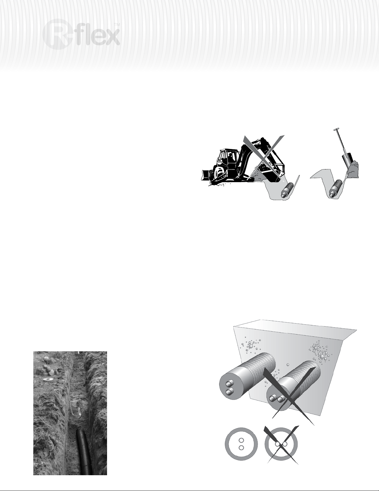
R-flex can easily be placed in earth-contact trenches. The corrugated jacket
provides the necessary protection for the insulating material and the PEX pipe.
Groundwater has no influence on the R-flex system. When laying the R-flex
directly into the trench, be careful not to pull the piping by the outer jacket.
Doing so may cause damage to the corrugation of the jacket. Pull R-flex by
grabbing the carrier pipes – never pull the jacket.
When uncoiling the pipe, please take care to ensure the pipe is not dragged
along the ground. Doing so can cause the R-flex to be damaged by sharp
objects. It is important to maintain control of the ends of each R-flex coil to
prevent pipe ends from whipping back when untying the textile straps. The
bending radii (see product data sheet) must not fall below the prescribed
minimum during installation or when positioning the pipeline. Pipes must be laid
in a serpentine course and may be covered with sand at regular intervals to
prevent unwanted movement. General guidelines for laying underground pipes
must be followed.
When laying larger dimensions and lengths, pulling devices such as winches or
tail-end rollers may be used. Always connect these devices to the carrier pipe.
The carrier pipe ships from the factory with fitted protective end caps to
prevent the entry of dirt and debris into the R-flex. Do not remove these caps
until ready to connect the R-flex to a fixed connection.
Since the R-flex pipe is laid in a serpentine pattern, it is necessary to design for
more pipe length than the measured trench length.
backll has been brought to about 20" (50 cm) above the top of the pipe, a
vibrating tamper may be used to compact the remainder of the soil. Do not
use a backhoe or other mechanical device to fill the first layer of the trench as
damage to the R-flex may occur.
Transitions
When transitioning R-flex across a structural wall, be sure to keep the Dual
pipe oriented in the vertical plane, as shown. Failure to do this will cause
connection issues at necessary intersections.
The point where the R-flex penetrates the structure must be sealed. This can
be done in a variety of ways, depending on the wall construction.
Backfilling Guidelines
Carefully place the R-ex pipeline on a compacted 4.0” (10 cm) bed of sand
on the bottom of the trench. The quality of this sand bed providing uniform
support for the pipe line has a decisive influence on the compressive stress of
the system. Make sure that the pipes are fully covered with sand
(granularity of 0-3mm).
Backfilling should be in layers of
about 8.0" (20 cm) and compacted
by hand. Care should be taken to
remove any sharp objects from the
backfill material. When the backfill has
been brought to about 20.0" (50 cm)
above the top of the pipe, a vibrating
tamper may be used to compact the
remainder of the soil. There should
also be a warning tape bearing the
legend “water pipe” laid directly above
the pipe.
Once the trenches are excavated, the
first layer of backfill should be carefully
compacted with a shovel. When the
Page 8
8
insulated piping system
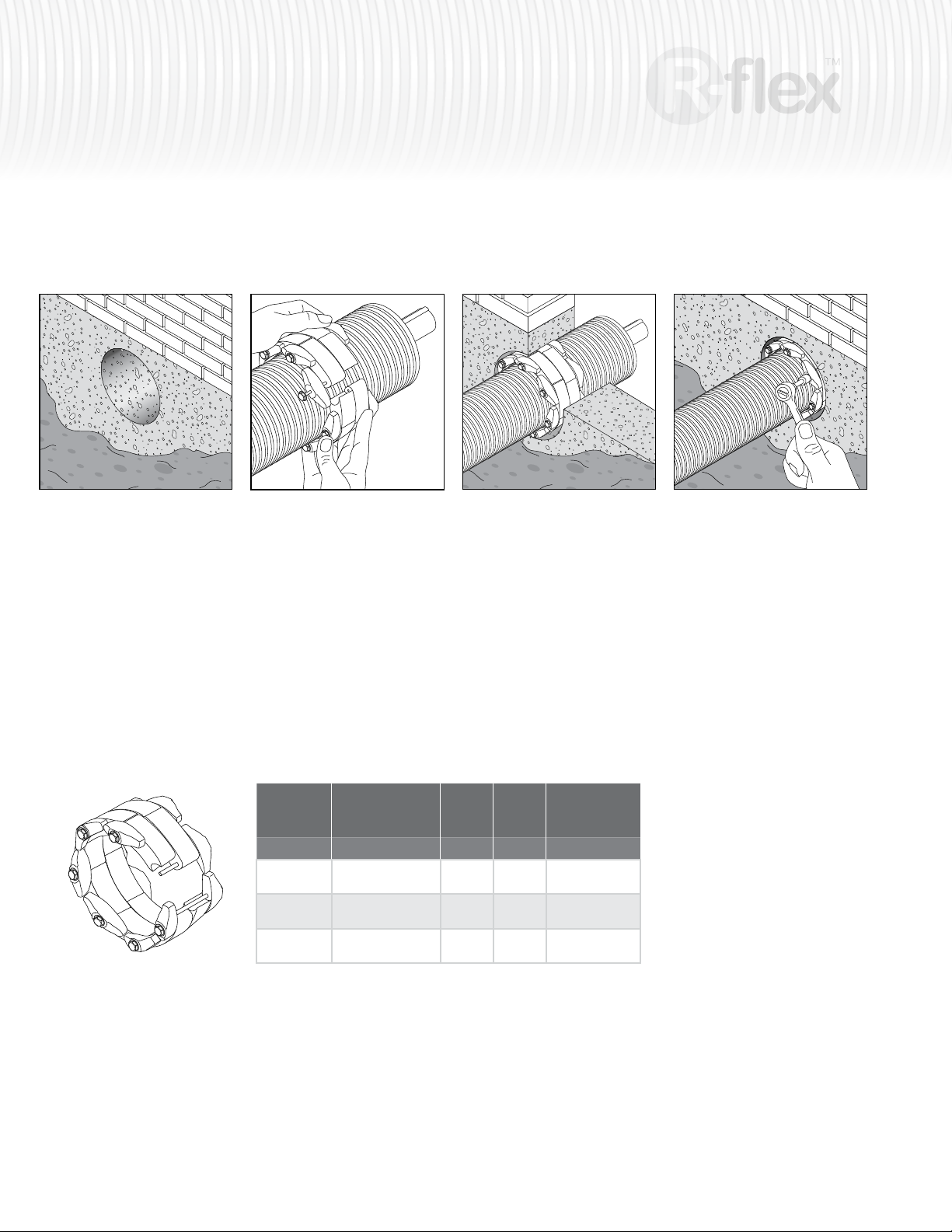
Wall seals are available in two styles: a Link Sleeve, and a Wall Sleeve. The
Link Sleeve is designed to be used when transversing existing walls. The Wall
Sleeve is to be used when a concrete wall is to be poured around the R-flex.
Link Sleeves
1. Drill a hole according to minimum and
maximum dimensions (see column
wall opening).
Center the pipe, cable or conduit in
wall opening or casing. Make sure the
pipe will be adequately supported on
both ends.
2. Loosen rear pressure plate with nut
just enough so links move freely.
Check to be sure all bolt heads are
facing the installer. Extra slack or sag
is normal.
Make sure the pipe is held straight
for at least 2 ft (60 cm) before and
after the belt. Bends are not allowed.
Link Belt Description Links
Order #
81012948
81012949
81012950
LinkBelt, 125mm
outer casing
LinkBelt, 160mm
outer casing
LinkBelt, 200mm
outer casing
3. Slide belt assembly into annular
space. Start inserting Link-Seal
modular seal assembly at the 6
o’clock position and work both sides
up toward the 12 o’clock position
Req’d
15 125 mm
15 160 mm
17 200 mm
outer
jacket
Ø
wall opening
152 mm
(6.00 in)
203.3 mm
(8.00 in)
254 mm
(10.00 in)
4. Using a hand socket or offset wrench
ONLY, start at 12 o’clock. Do not
tighten any bolt more than 4 turns
at a time. Continue in a clockwise
manner until links have been
uniformly compressed. (Approx. 2 or
3 rotations)
5. Make 2 or 3 more passes at 4
turns per bolt MAXIMUM, tightening
all bolts clockwise until all sealing
elements “bulge” around all pressure
plates.
Link-Seal® Modular Seal - Do’s
1. Make sure pipe is centered.
2. Install the belt with the pressure
plates evenly spaced.
3. Make sure seal assembly and pipe
surfaces are free from dirt.
4. For tight ts, use non-polluting liquid
detergent to assist installation.
Link-Seal® Modular Seal - Don’ts
1. Don’t Install the belt with the pressure
plates aimed in irregular directions.
(Staggered)
2. Don’t torque each bolt completely
before moving on to the next.
3. Don’t use high speed power tools
(450 rpm or more)
4. Don’t use grease installing Link-Seal
modular seals.
Page 9
insulated piping system
e
Ø D1
Ø D2
430
Wall Sleeves
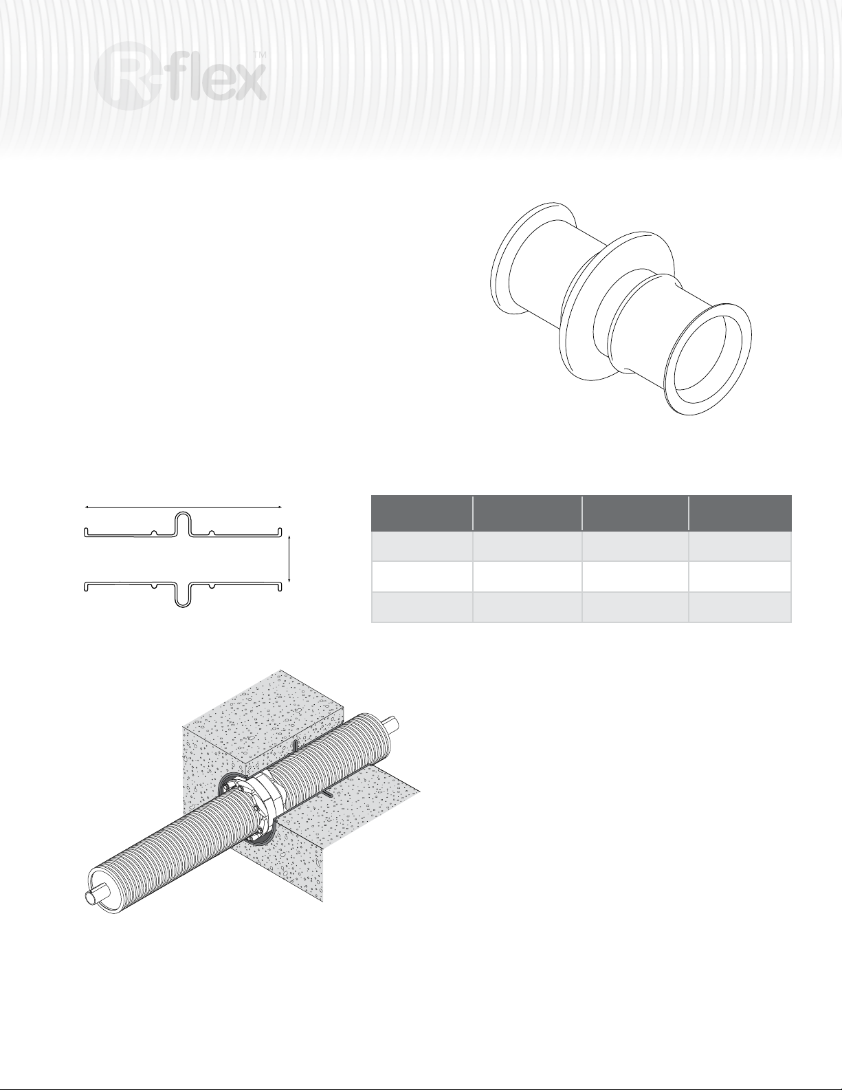
Where pipes must pass through walls and floors of new structures, molded
nonmetallic high density polyethylene CS sleeves can be installed.
Molded-in waterstop and reinforcing ribs serve to anchor the sleeve in the
wall and resist pour forces. Nailer end caps are provided to make placement
in forms simple and accurate. In the event of a field change they can be
shortened with ordinary hand tools.
The sleeve is purposely molded with a texture on the outside surface to assure
a much better bond than most plastic-to-concrete interfaces.
Each Wall Sleeve comes complete with corresponding sizes LinkBelts to
complete the seal between the R-flex and the Wall Sleeve.
9
R-flex Wall sleeve
L
Order #
81012931 125 mm
81012932 160 mm
81012933 200 mm
Ø pipe jacket D1 L
(4.92 in)
(6.30 in)
(7.87 in)
208.5 mm
(8.21 in)
208.5 mm
(8.21 in)
258.8 mm
(10.19 in)
406.4 mm
(16.in)
406.4 mm
(16 in)
406.4 mm
(16 in)
Wall Sleeves come complete with end caps and corresponding Link Belts.
1 Nailer end caps are installed at
each end of the sleeve to prevent
deformation during the initial
concrete pour and hold sleeve
in exact location. Place one end
cap at each end of the sleeve.
2 Remaining end cap is inserted
into sleeve. Wide flange area
on cap provides good surface
against wall form, and resists
weight of concrete pour.
3 Workman checks sleeve
installation prior to erecting
outside form wall.
4 Keep end caps in place after wall
is poured and the form has been
removed. The end caps seal
sleeve against dirt and debris.
5 Just before pipe penetration,
caps are removed to reveal
clean inside surface of sleeve.
Page 10
10
insulated piping system
On the interior side of the wall, secure an “L” bracket to the wall to support the
R-flex as it transitions through the wall. Install either a dust cap or a shrinkable
end cap to the protruding end of the R-flex to keep dirt, debris, and possibly
water from entering the inner casing. Do this before installing any connections
or fittings.
R-flex must be supported at transition points to hard piping in the
structure. Failure to do so may void the warranty. There can be significant
expansion and contraction movement of the PEX carrier pipe which may cause
connection leaks and/or damage to hard piping. R-flex can not be run internally
(run inside the building). Transition from R-flex to a suitable carrier pipe rated
for interior applications.
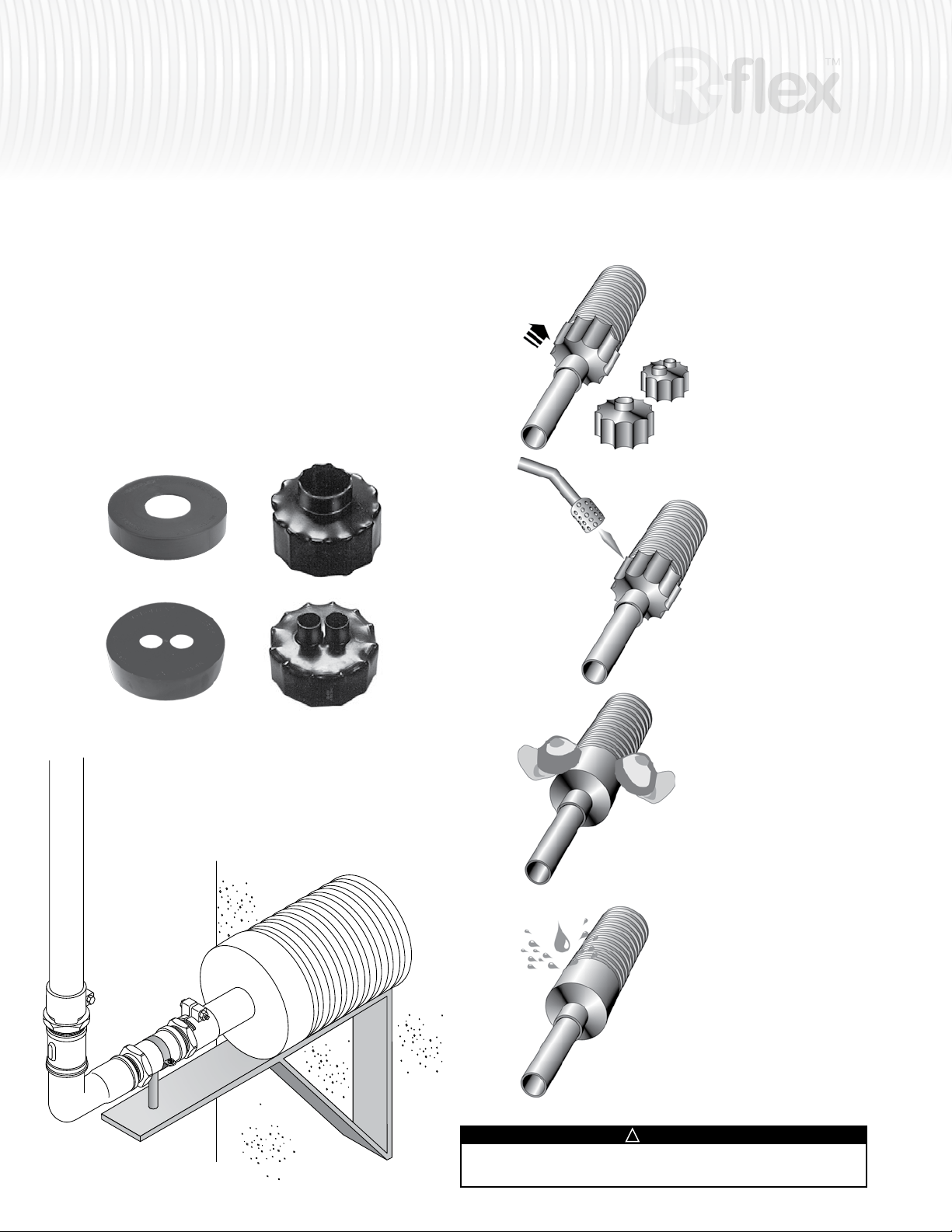
Guidelines for installing shrinkable end caps.
1
Slide the cap over the
carrier pipe and the
jacket.
2
Use a heat gun or mini
torch with soft yellow
flame (DO NOT use a
blue flame!) to gently
shrink the cap. Extra care
should be taken not to
damage the outer jacket.
Non waterproof dust caps Waterproof shrink caps.
R-flex must be supported at transition points into the structure. R-flex can not
be run inside the building. Transition from R-flex to a suitable carrier pipe rated
for interior applications.
3
Press the cap, wearing
protective gloves.
4
The tail end of the pipe is
now sealed watertight.
!
WARNING
Keep hands away from any open flame. Do not touch – surface of shrink-
wrap will be hot. Wear gloves when handling.
Page 11
insulated piping system
11
Intersections
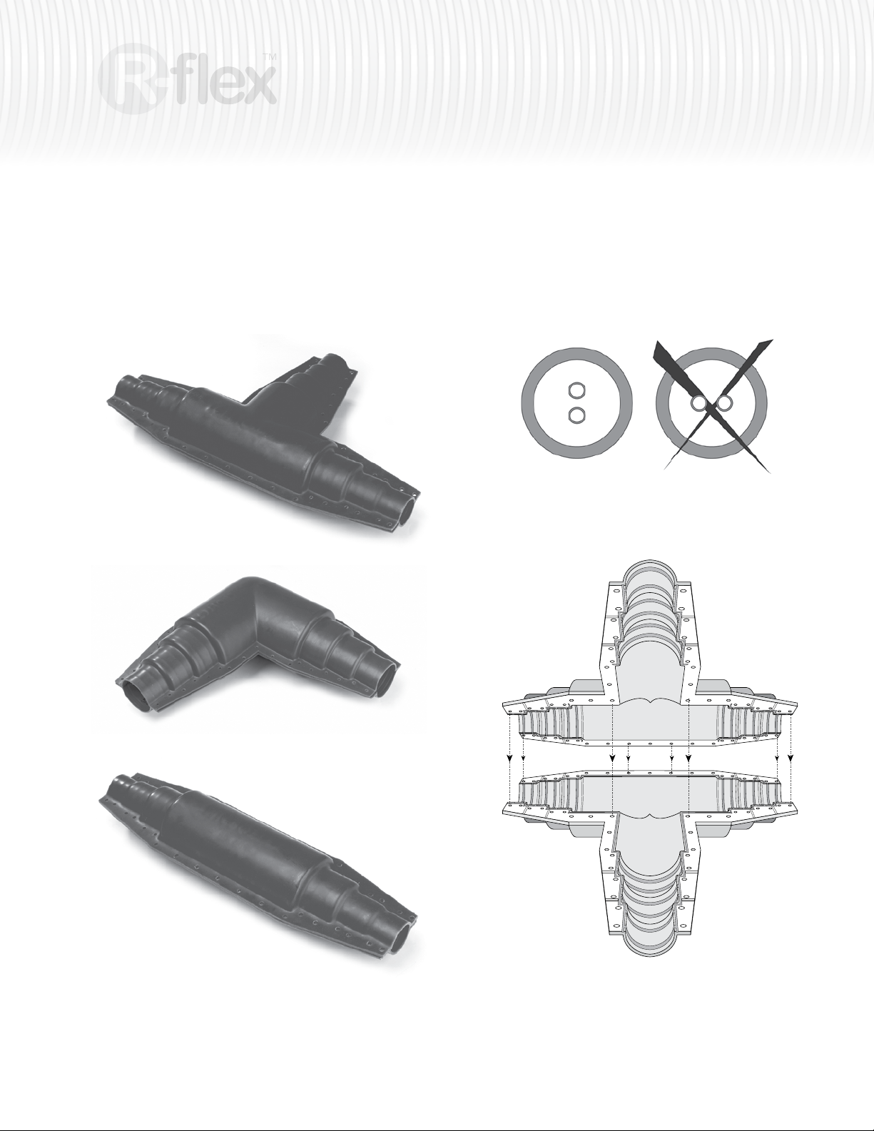
Intersections generally consist of (1) branch tees, (2) elbows, or (3) mid-run
couplings used to extend a run of R-flex. Each of these connections need to
be encased in a connection casing - a waterproof protective shell.
1
2
When creating an intersection, make sure to follow these guidelines fully in
order to maintain the warranty.
Keep R-flex Dual systems oriented in the vertical plane, as illustrated below.
This will allow for proper assembly of the internal connections. This is especially
critical when installing Tee intersections.
3
Casings provide additional insulation and seal outer jacket where field
connections are made. The set comes with stone wool (insulation), a
ready to use bitumen rubber kit, stainless steel bolts and an instruction
leaflet. Heat shrinkable caps to be ordered separately.
Make sure the area where casings are to be installed is square with the R-flex
entering and exiting the casing. Failure to do so will cause complications later
when trying to assemble the upper half of the casing, and may create an
improper seal at the transition points.
Holes in both shell-shaped casings (top and bottom) are identical and are
pre-drilled allowing for quick, easy installation.
Page 12
12
insulated piping system
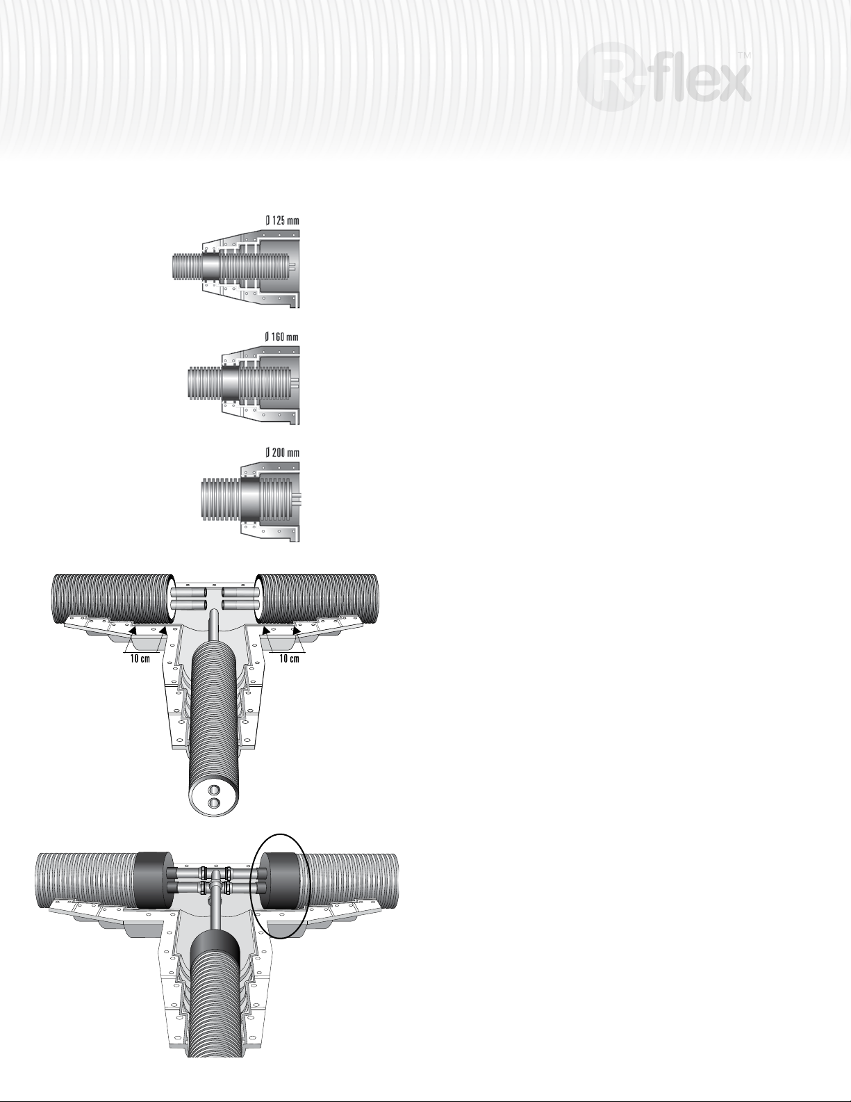
All casings have a series of stepped collars at each point of entry. These
are designed to fit each of the three main outer jacket sizes of
R-ex – 125 mm, 160 mm, and 200 mm respectively. These steps are
to be cut to accommodate the size of pipe being used.
Trim the casings before installing them in the trench. Inserting the R-flex into
the lower half of the casing will facilitate gauging of fit and trim points on the
R-flex.
Do not cut a step intended for larger R-flex than being used. Doing so will
cause an improper seal at the transition point.
(4 in)(4 in)
The end of the R-flex pipe must
be positioned in the noted area
of the casing.
Use the casing as a guide when determining how much of the outer jacket to
remove. The outer jacket must extend 4” (10cm) past the last step (marked
for 200mm). Mark the R-ex and carefully remove the outer jacket and insula-
tion – taking care not to damage the internal PEX piping.
Replace the R-flex in the casing and mark where to trim the PEX pipe.
Apply the shrink caps, using the techniques described in the Transition section
of the manual.
Apply connections to the PEX tubing. Make sure the outer Jacket remains
within the 200 mm step of the casing.
Page 13
insulated piping system
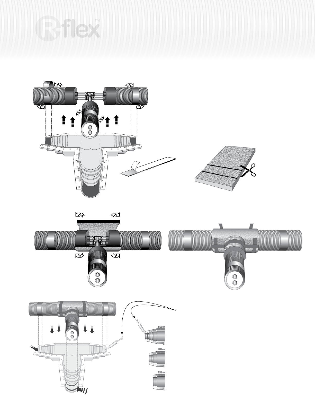
Each casing kit comes with bitumen strips (2 with couplings and elbows, 3 with
tees) and an insulation blanket. Cut the strips to fit the pipe size. Do not cut the
strips so they overlap as an improper fit will result at the entry point.
Remove the protective layer and fit the bitumen strips to the outside of
the R-ex jacket and inside of the insulation casings at the (2 or 3) pipe
entry points.
Ø 125 mm
Ø 160 mm
13
It is not necessary to cut for 200 mm
Wrap the insulating blanket, cut to the desired size,
around the carrier pipe so that the connections are
properly covered. Make sure to cover the shrink
cap. Tape the insulated blanket in place.
Apply a uniform bead of sealant to the grooves of both the
upper and lower shell casings. Keep the bead to a thickness of
about 5/32" (4 mm) to 3/16" (5 mm wide).
Insert the R-flex into the lower casing.
Page 14
14
insulated piping system
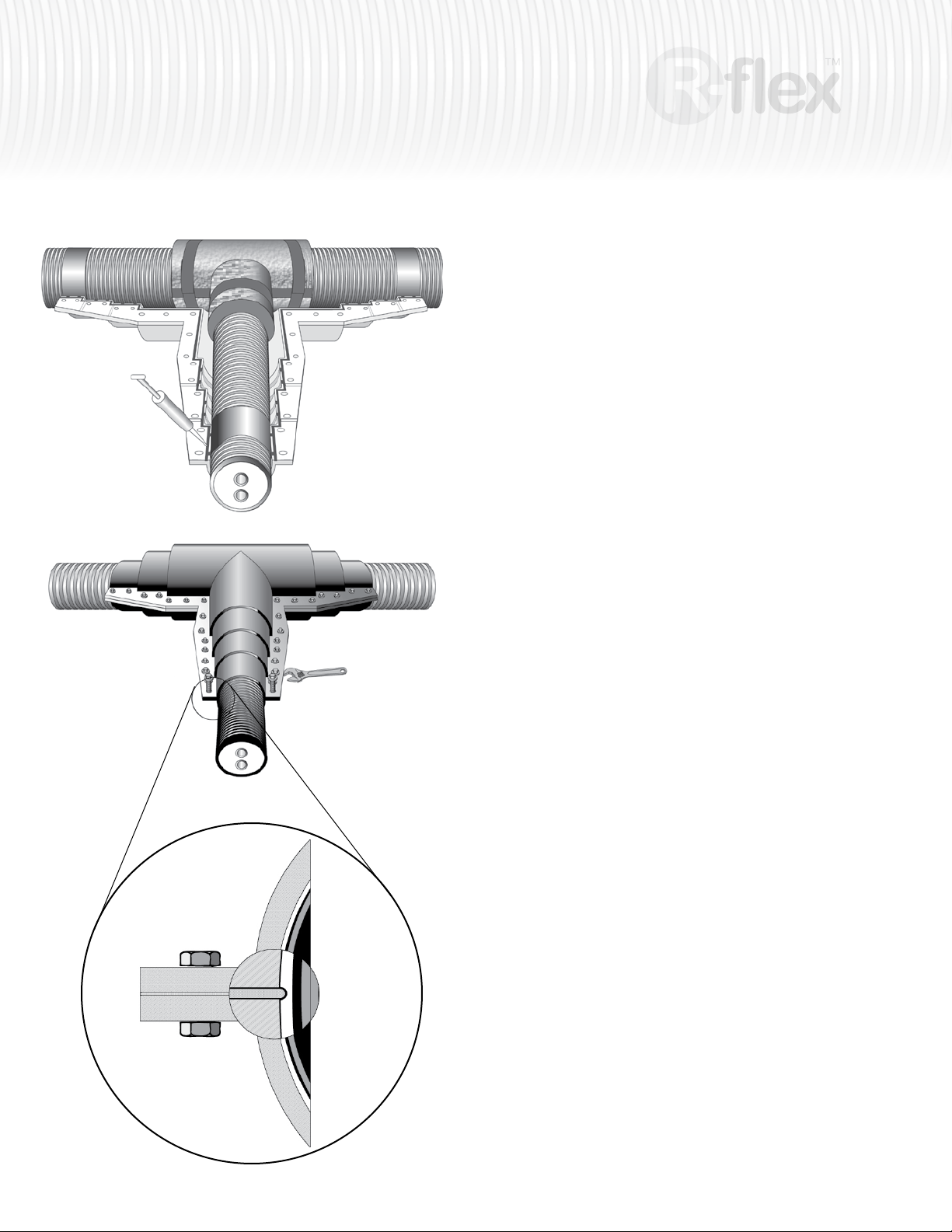
Apply sealant at a uniform rate along flanges of top and bottom casing (next to
the drilled holes) to yield a thickness of about 1/4" (6 mm).
Carefully align the two casing halves and insert the stainless steel bolts.
Tighten the stainless bolts.
Check that the sealant is being squeezed through the side of the
casing. This will indicate proper distribution of the sealant across
the casing flange.
Page 15
insulated piping system
15
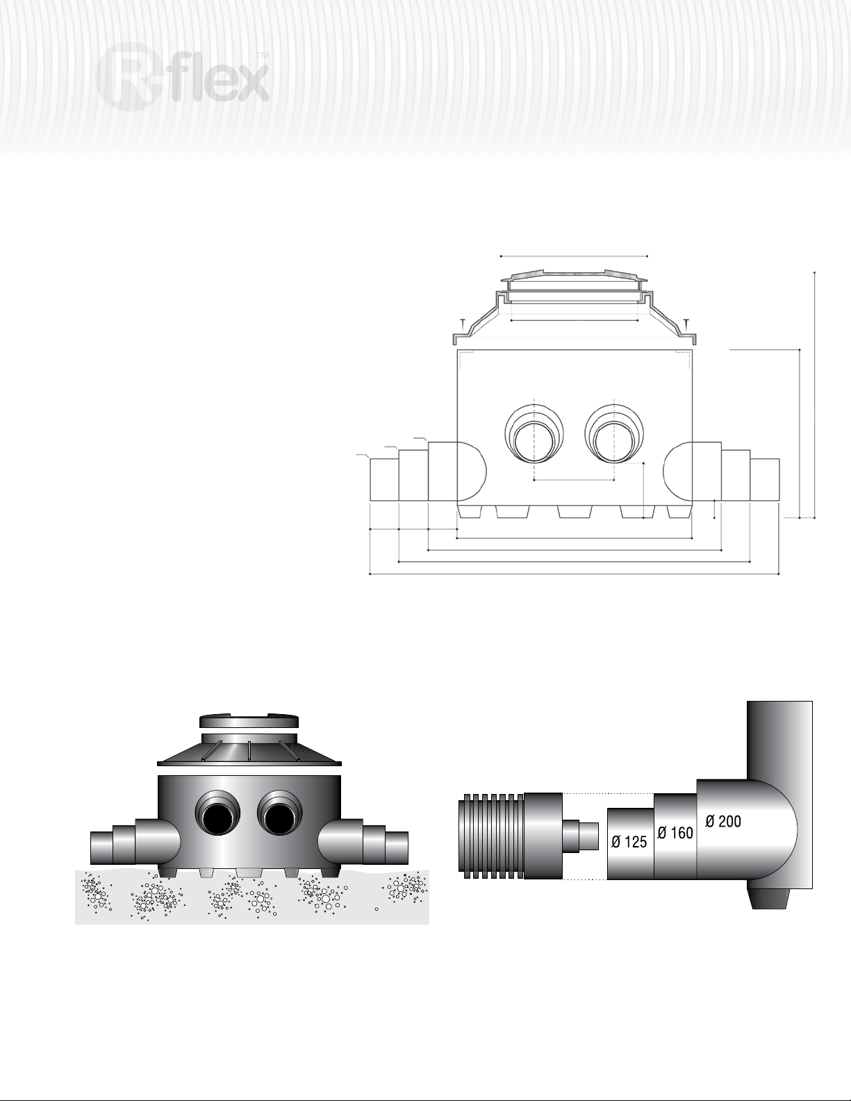
Inspection Chamber
Inspection chambers allow access to
connections and valves after R-flex is installed
and can be used as an alternative to the
individual connection casings. Each chamber
is equipped with 6 marked entries that can
be cut to suit various opening sizes (125, 160
or 200 mm).
Each inspection chamber comes with a top lid,
stainless bolts, and an instruction sheet.
The following steps will lead to establishing a
waterproof connection.
Installation
Entries are marked and are to be cut off to suit
the desired opening sizes. Carefully lower the
inspection chamber on a level bed of sand, free
of sharp objects.
Ø 160mm
Ø 125mm
Ø 200mm
100
4.0"
100
4.0"
100
4.0"
Ø 455mm
Ø 18.0"
Ø 380mm
Ø 15.0"
270mm
10.5"
Ø 810mm Ø 32.0"
1010mm 40.0"
1210mm 47.5"
1410mm 55.5"
220mm
8.5"
65mm
2.5"
23.5"600mm
30.3"770mm
Page 16
16
insulated piping system
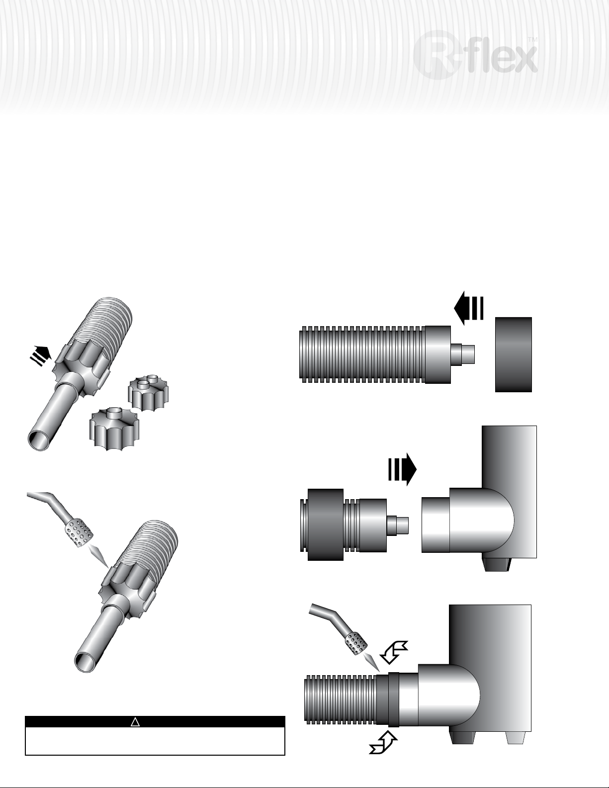
Connections
Before connecting the R-flex in the inspection chamber, slide a shrink cap
(1) over the jacket and the carrier pipe. Use a heat gun (2) or mini torch with
soft yellow flame (do NOT use a blue flame!) to gently shrink the cap.
Further information on applying the shrink caps can be found in the section
Guidelines for installing shrinkable end caps.
The use of the shrink cap is mandatory for any casing installation.
Slide a shrink sleeve (3) over the jacket, prior to pushing (4) the R-ex pipe
into the inspection chamber.
Make all necessary connections in the chamber.
Slide the shrink sleeve back over the edge of the inspection chamber (5) so it
covers both the chamber and the R-flex outer jacket. Gently shrink the sleeve
onto the jacket, using a heat gun or a mini torch to ensure a waterproof
connection between jacket and inspection chamber.
The use of the shrink sleeve is mandatory for any casing installation.
1
3 Shrink sleeve
4
2
!
WARNING
Keep hands away from any open flame. Do not touch – surface of shrink
wrap will be hot. Wear gloves when handling.
5
Page 17
insulated piping system
17
Branching possibilities
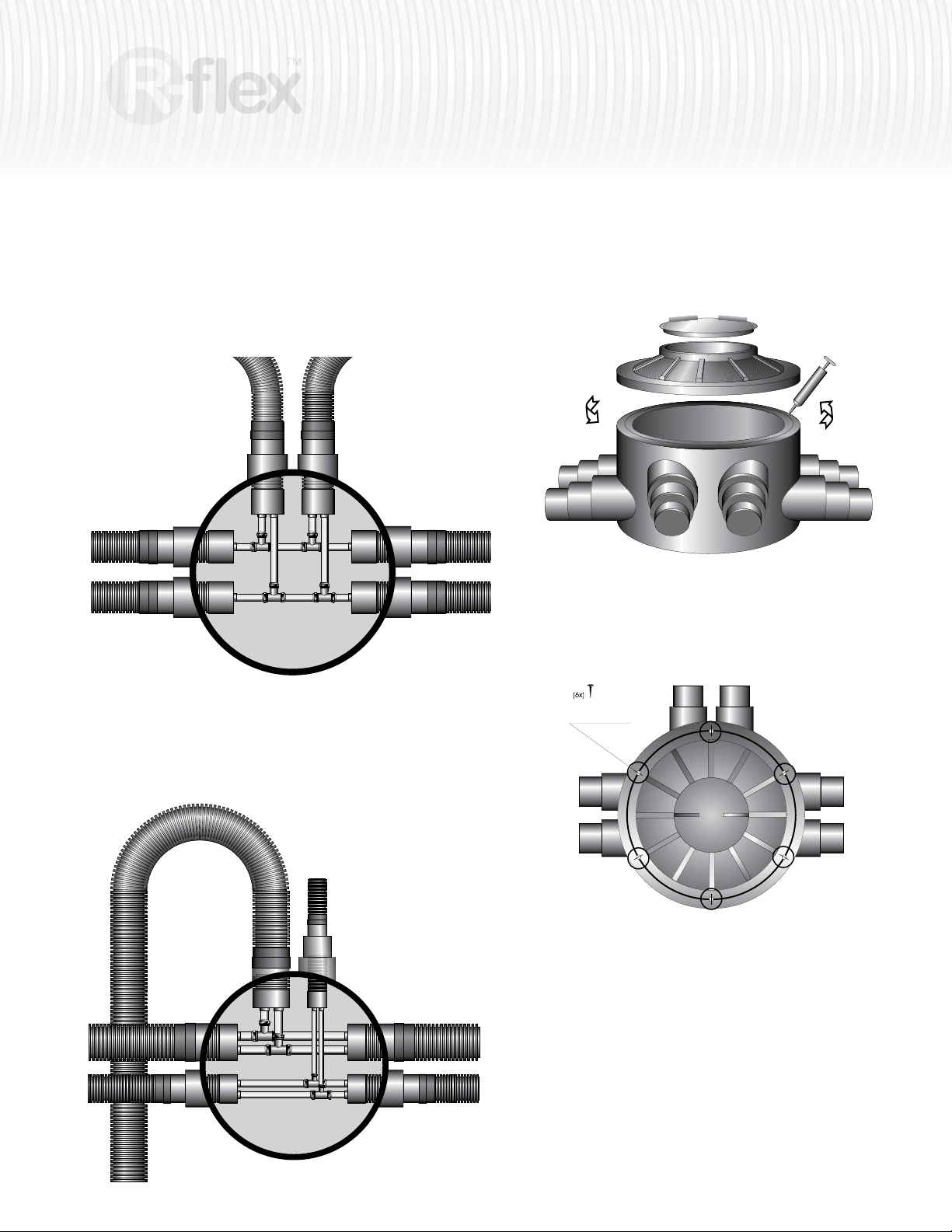
The inspection chamber, made of shock-resistant polyethylene, is very
solid. It offers the possibility of:
• branching from Single to Dual R-ex pipes
Sealing of inspection chamber
Apply sealant at a uniform rate, to edge of chamber body part to yield a thickness
of about 0.4" x 0.4" (10 mm by 10 mm wide).
Place the pitched top on the body part.
Install the 6 stainless screws.
• branching from Dual to Dual R-ex pipes
• branching of several Dual pipes having various diameters
Install the screws
Carefully turn the lid clockwise to lock
it. Do not damage the black gasket
between body and top part.
Do not use excessive force.
Page 18
18
100 mm
100 mm
150 mm
150 mm
≥ 250 mm
≥ 400 mm
insulated piping system
Covering
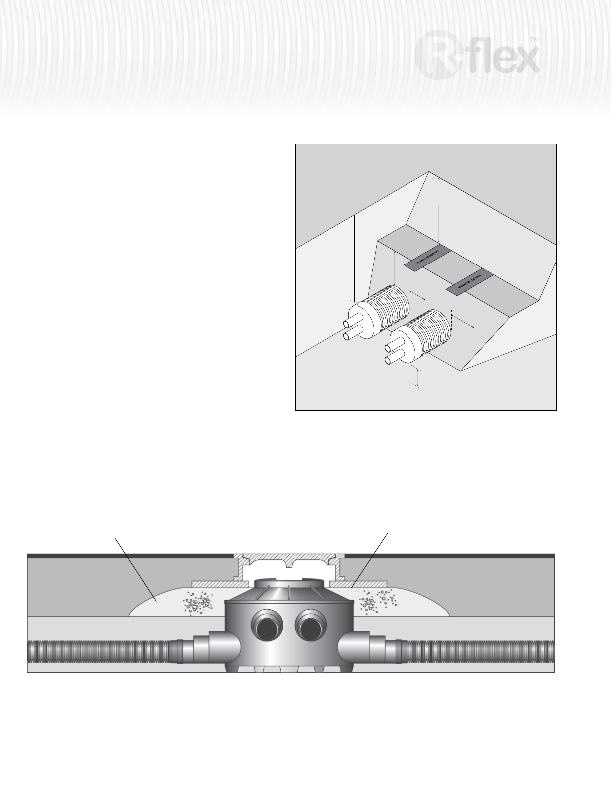
The type of surface loading expected over the inspection chamber and R-flex
pipe will determine the necessary installation depth. Refer to section Backfilling
Guidelines for further information on depth and covering requirements. Check
local codes to determine minimum pipe depth with relation to surface loads. Local codes may require different depths than those illustrated in this manual.
The inspection chamber needs to be positioned to allow the R-flex to enter
the chamber without stress or bending. This may result in the chamber being
below grade.
Always consider where the frost line is when determining trench
depth. R-flex should always be installed below frost line.
9.85"
15.75"
5.90"
3.95"
5.90"
Covering of the inspection chamber
Cement stabilized sand
3.95"
Check local code to determine minimum pipe depth with relation to
surface loads.
Concrete ring
Page 19
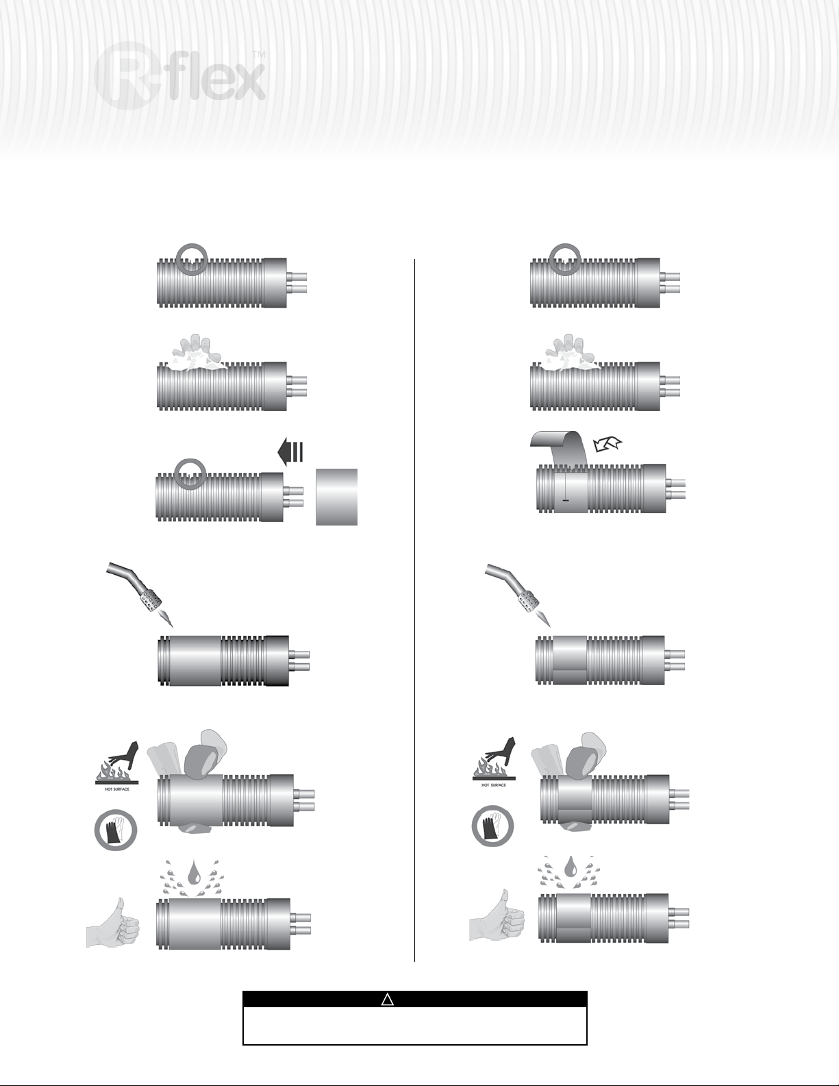
Outer Jacket Repairs
For Repairs Using Shrink Sleeve For Repairs Using Shrink Tape
Locate damaged area. Locate damaged area.
19
insulated piping system
Make sure the jacket of the pipe is dry and clean.
Slide the shrink sleeve over the damaged R-flex pipe.
NEVER CUT THE SLEEVE LENGTHWISE!
Use a heat gun or mini torch with soft yellow ame (do NOT use
a blue flame!) to gently shrink the repair sleeve.
Make sure the jacket of the pipe is dry and clean.
7cm
Wrap the repair tape around the damaged jacket, overlap-
ping each preceding layer by about 7 cm (2.75").
Use a heat gun or mini torch with soft yellow ame (do NOT use
a blue flame!) to gently shrink the repair sleeve.
Press the sleeve, wearing protective gloves.
The damaged jacket is now sealed watertight.
Keep hands away from any open flame. Do not touch – surface of
shrink wrap will be hot. Wear gloves when handling.
!
WARNING
Press the sleeve, wearing protective gloves.
The damaged jacket is now sealed watertight.
Page 20
20
insulated piping system
Appendix A system design
R-flex U.S. equivalents
Metric 25 mm 32 mm 40 mm 50 mm 63 mm 75 mm 90 mm 110 mm
US Equivalent 1" 1-1/4" 1-1/2" 2" 2-1/2" 3" 3-1/2" 4"
Single
Dual
Required calculation steps:
1. Select the right pipe diameter:
-Calculate the heat transfer.
-Select the (carrier) pipe dimension for which the ow velocity does not exceed 7 ft/sec.
-Choose either Single or Dual pipe system.
160 mm 81012929 81012886 81012887
200 mm 81012889 81012890 81012891
125 mm 81012879 81012880
160 mm 81012882
200 mm 81012884 81012885
2. Determine the total physical pipe length:
-Split the pipe length into straight and angled segments.
- Calculate the equivalent length of the angled segments (as a function of the tightest suitable bends achievable with the specific
pipe dimension.
-After the length of all segments have been determined, simply add them all together and add 5%.
Rule of Thumb
To accommodate for the thermal expansion forces and minimize the forces on the fittings:
-A 5% add-on on the total length is required
-To be distributed over the total length (serpentine)
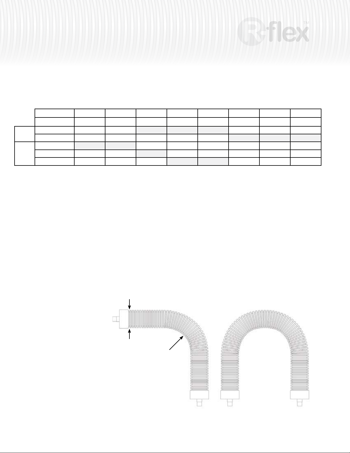
Bending angle into equivalent length:
L = a/180 x π x (R + d/2)
a = the angle of the bend from its center
R = bending radius based on the inside radius
d = outer diameter HDPE-outer jacket
Example 45° turn:
L = 45/180 x 3.14 x (12 + 8/2)
L = 12.5 inches
L = 1.05 ft
Example 90° turn:
L = 90/180 x 3.14 x (12 + 8/2)
L = 25.13 inches
L = 2.09 ft
d
R
a=90 a=180
Example 180° turn:
L = 180/180 x 3.14 x (12 + 8/2)
L = 50.27 inches
L = 4.19 ft
Page 21
Single
Dual
insulated piping system
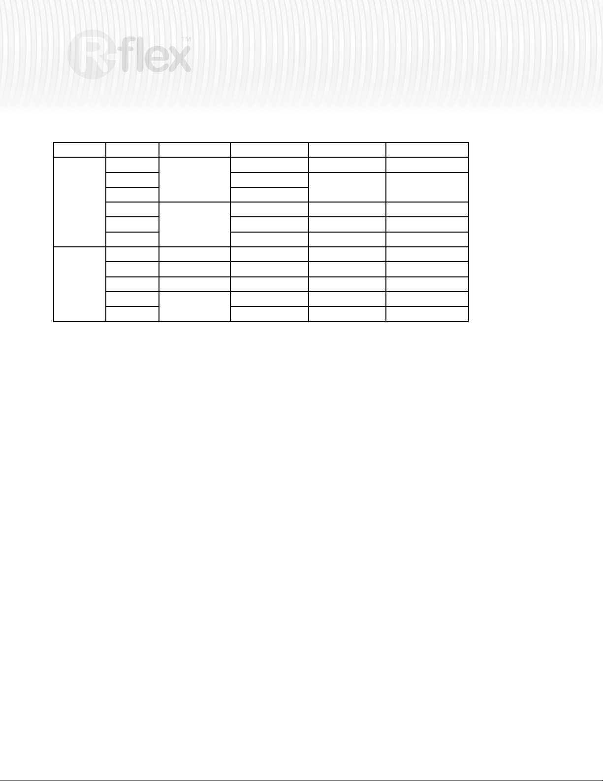
Description Jacket OD Bend Radius 45° Bend 90° Bend
160/40
160/50 450 mm (17.8 in)
160/63 550 mm (21.7 in)
200/75
200/90 1100 mm (43.4 in) 491 mm (1.61 ft.) 981 mm (3.22 ft)
200/110 1200 mm (47.3 in) 539 mm (1.77 ft.) 1079 mm (3.54 ft)
125/2x1” 4.9 in (125 mm) 11.8” (300 mm) 0.85 ft (259 mm) 1.7 ft (518 mm)
125/2x32 125 mm (4.9 in) 300 mm (11.8 in) 259 mm (0.85 ft.) 518 mm (1.7 ft)
160/2x40 160 mm (6.3 in) 600 mm (23.7 in) 512 mm (1.66 ft.) 1024 mm (3.36 ft)
200/2x50
200/2x63 1200 mm (47.3 in) 850 mm (2.79 ft.) 1700 mm (5.58 ft)
160 mm (6.3 in)
200 mm (7.9 in)
200 mm (7.9 in)
350 mm (13.8 in) 305 mm (1.00 ft.) 610 mm (2.00 ft)
433 mm (1.42 ft.) 866 mm (2.84 ft)
800 mm (31.5 in) 485 mm (1.59 ft.) 969 mm (3.18 ft)
800 mm (31.5 in) 639 mm (2.10 ft.) 1278 mm (4.19 ft)
21
3. Calculate the heat load at the source
(as a function of the target heat capacity at recipient side)
Determine heat transfer losses:
- Calculate ΔT as the temperature differential between the surrounding soil temperature and the temperature in the carrier pipe(s).
- Locate this ΔT along the X axis of the corresponding graph
- Read the heat loss at the corresponding coordinate.
- Multiply the heat loss per unit with the total pipe length to obtain the total transfer losses.
Heat load at source = required capacity + transfer losses
Rule of Thumb
Ground temperature: for planning purposes a ground temperature of about 50°F (10°C) is a realistic assumption [minimum laying
depth of 2.0 ft (600 mm) to 3.2 ft (1000 mm)
4. Determine pressure loss in the system
Calculate the total equivalent length of the system, by including the length equivalent of all brass fittings
Use the “Pressure Loss Table” to determine the pressure loss per 100 feet of Single R-ex or per 50 feet of Dual R-ex.
Complete Pressure Loss Tables are found in the back of this Manual.
Single R-flex
Divide the total length (supply, return, bends, fittings, etc) by 100. Multiply this length of the system with the pressure drop per 100’
found in the table to obtain the system’s overall pressure loss (head loss).
Dual R-flex
Divide the total length (supply, return, bends, fittings, etc) by 50. Multiply this length of the system with the pressure drop per 50’ found
in the table to obtain the system’s overall pressure loss (head loss).
Page 22
22
0
5
10
15
20
25
30
35
40
45
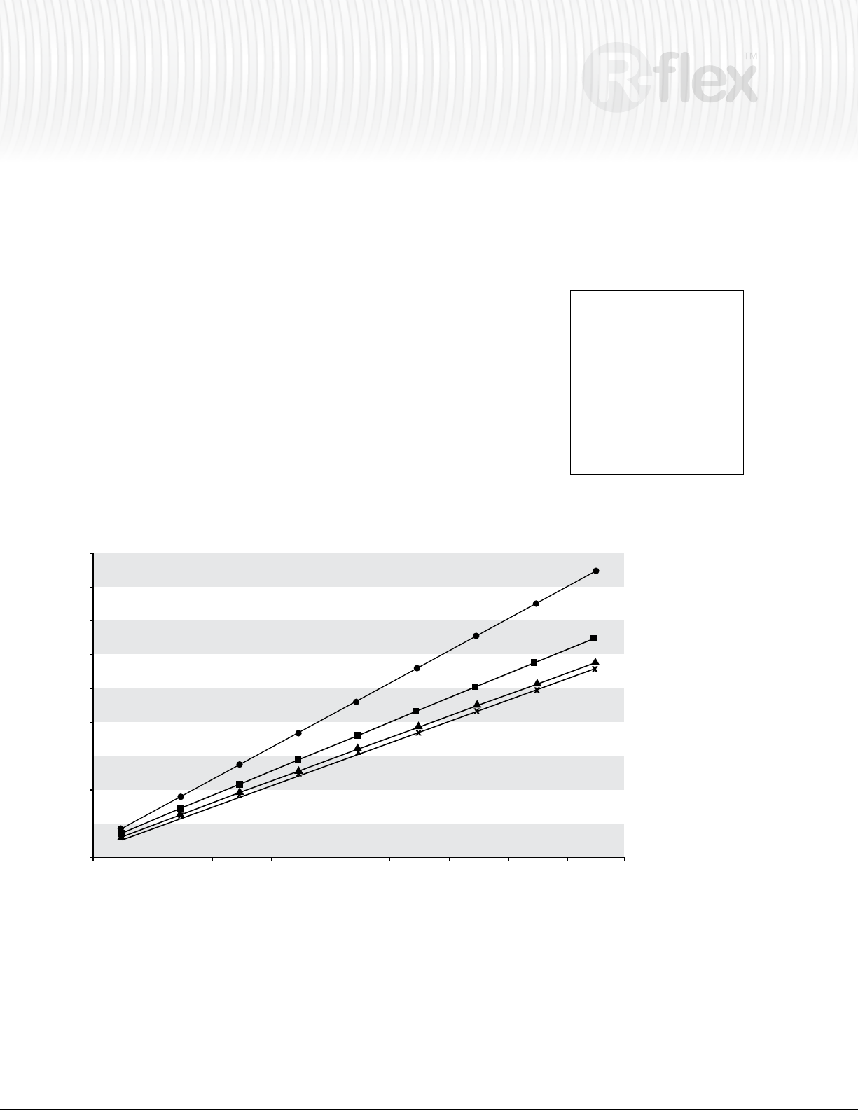
Heat losses in W/m
Δ T
10 20 30 40 50 60 70 80 90
160/2 x 40
200/2 x 63
200/2 x 50
∅ jacket
125/2 x 32 and 1”
Appendix A cont’d
Heat losses
The values used in calculating the heat loss are:
insulated piping system
– Insulation 0.0365 W/m.K (0.0211 BTU/hr.sq.ft.°F)
– Ground 1.2 W/m.K (0.693 BTU/hr.sq.ft.°F)
– PEX pipe: 0.35 W/m.K (0.202 BTU/hr.sq.ft.°F)
Depth of cover over top of pipe: 50 cm (20")
With the ΔT being calculated, the heat loss per length of piping can easily be
read along the corresponding line of the table.
R-flex Dual
(BTU/hr.ft)
(26.0)
(23.1)
(20.2)
(17.3)
(14.4)
(11.6)
For Dual
(T
+Tr)
v
2
- T
o
ΔT =
: Fluid supply temperature
T
v
: Fluid return temperature
T
r
: Ground temperature
T
o
(8.7)
(5.8)
(2.9)
(0)
18 36 54 72 90 108 126 144 162 ∆T °F
** May not currently be offered.
°C
Page 23
insulated piping system
0
5
10
15
20
25
30
35
40
45
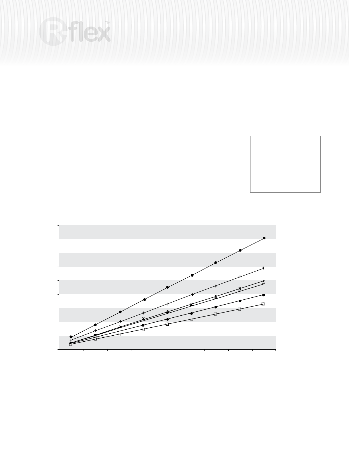
Heat losses in W/m
Δ T
10 20 30 40 50 60 70 80 90
200/110
200/90
∅ jacket
160/63
200/75
160/50
160/40
For Single
ΔT = T
- T
v
o
Tv : Fluid supply temperature
: Ground temperature
T
o
23
R-flex Single
(26.0)
(23.1)
(20.2)
(17.3)
(14.4)
(11.6)
(8.7)
(5.8)
(2.9)
(BTU/hr.ft)
(0)
18 36 54 72 90 108 126 144 162 ∆T °F
°C
Page 24
24
500 mbh
1500 mbh
Supply Return
Segment A
Segment B Segment C
Segment T
Segment D
Segment E
Segment F
D 1
D 2
insulated piping system
Appendix A cont’d design example
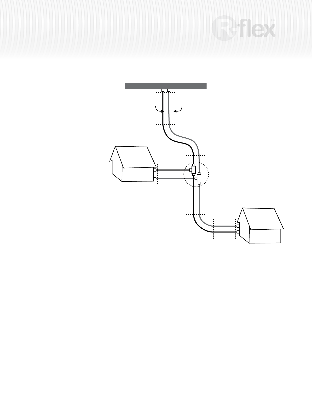
Calculating length to order:
Suppose:
A = 100 ft; B = C = 6 ft; D1 = 30 ft GPM: 200
T = 100 ft GPM = 50
D2 = 100 ft; E = 6 ft; F = 40 ft GPM = 150
Segment A – D1 requires 110 mm R-flex Single
Segment T requires 63 mm R-ex Single
Segment D2 – F requires 110 mm R-ex Single.
Supply Temp: 140°F (60°C)
Ground Temp: 50°F (10°C)
Total length to order:
(100+6+6+30) x 1.05 = 150 ft of 110 mm.
x 2 (for supply/return) = 300 ft.
100 x 1.05 = 105 ft of 63 mm
x 2 (for supply/return) = 210 ft.
(100+6+40) x 1.05 = 154 ft of 90 mm.
x 2 (for supply/return) = 308 ft.
Heat Loss: (supply and return)
-For all sectors: ∆T-ground = 90° F (50°C)
-A thru D1: 20 BTU/ft x 300 ft = 6,000 BTU/hr
-T: 7 BTU/ft x 210 ft = 1,470 BTU/hr
-D2 thru F: 9.5 BTU/ft x 308 ft = 2,926 BTU/hr
-TOTAL HEAT LOSS = 10,396 BTU/hr
-TOTAL LOAD: 2,000,000 BTU
Heat Lost through R-ex is less than .25% of the total load!
Pressure Loss through pipe with 140°F Water:
-A thru D1: 300 ft; 200 gpm
3.23 ft hd / 100 ft x 300 = 9.69 ft hd.
-T: 210 ft; 50 gpm
3.89 ft hd / 100 x 210 = 8.17 ft. hd.
-D2 thru F: 308 ft; 150 gpm
1.92 ft hd / 100 x 308 = 5.91 ft hd
MAX HEAD PRESSURE = 17.86 + LOSS THROUGH “T”
(Does not include fittings)
Page 25
insulated piping system
Appendix B pressure drop charts
Pressure Drop Methodology
Calculating pressure drop through a tube or circuit is dependent on a wide range of factors – viscosity, density, flow rate, and tube conditions.
Pressure drop (loss) in the circuits is determined using the Darcy-Weisback equation.These equations are referenced in ASHRAE's 2005 Handbook Fundamentals, section 2.0, equations 5, 18, 30, 32a, 32b, and 32c.
Glycol values referenced are based on DowFrost™ Technical Specication (form no. 180-01272-402AMS). Different glycol concentrations, types, and
formats will result in different pressure drop calculations. The data points provided should only be used as a reference point.
Data
25
DowFrost™ 50% Solution (extrapolated data)
Density
°F
(lbs/cu.ft.)
40 65.670 14.280
60 65.210 12.394
80 64.750 10.509
100 64.290 8.623
120 63.830 6.737
140 63.370 4.851
160 62.910 2.966
180 62.450 1.080
* derived equation used for extrapolation: y = 8473.8x
The table shown assume an approximate mixture of water/glycol of 50% concentration. Actual
pressure drop values will change depending on actual concentrations and fluid temperature.
Dynamic Viscosity
(cps)*
Dynamic Viscosity
(lb/ft-s)
0.0096
0.0048
0.0029
0.0020
0.0014
0.0011
0.0009
0.0007
(-1.7307)
Calculations
Where:
HL = Head Loss in feet per 100 feet of pipe
f = Friction factor
L = Length of pipe (ft)
V = Fluid velocity (ft/sec)
d = Pipe inside diameter (ft)
g = Gravity (32.2 ft/sec2)
Re = Reynold's number
e = Pipe roughness factor (est. 3.0E-6)
Water
Density
°F
(lbs/cu.ft.)
80 62.22 0.858 0.00058
100 61.99 0.681 0.00046
120 61.71 0.557 0.00037
140 61.38 0.466 0.00031
160 61.00 0.398 0.00027
180 60.58 0.345 0.00023
Dynamic Viscosity
(cps)
2
LV
HL = f
d2g
f = 8
8
Re
A = 2.457 ln
37,530
B =
Re
12
16
+
(7/Re)
(A+B)
0.9
Dynamic Viscosity
(lb-ft-s)
1/12
1
1.5
1
+ (0.27e/d)
16
Page 26
26
insulated piping system
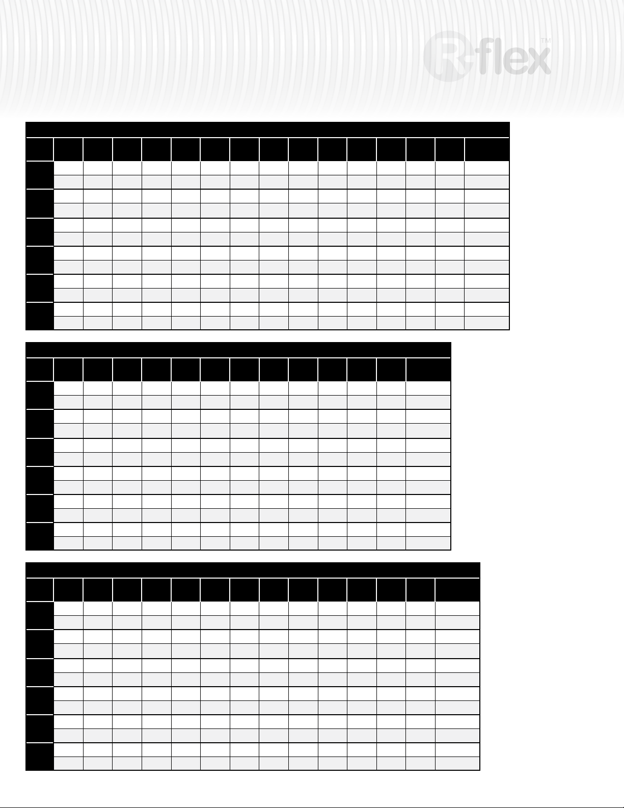
50 mm R-flex Single, Pressure Drop per 100' (1.79" Nom. ID)
11.00
12.00
13.00
14.00
15.00
16.00
17.00
°F
(1.78)
(1.94)
0.90
80°
100°
120°
140°
160°
180°
1.04
1.37 1.59 1.82
0.85 0.99 1.14
1.23 1.43 1.64 1.86
0.81
0.95
1.13 1.31 1.50
0.78
0.91
1.05 1.22 1.41
0.75
0.88
0.99 1.16 1.33
0.73
0.86
0.95 1.10 1.27
(2.11)
(2.27)
(2.43)
(2.59)
1.20 1.37 1.55 1.74 1.93 2.14 2.35 2.58 3.84 5.31 7.00 8.89
2.07 2.33 2.60 2.88 3.18 3.49 3.81 5.61 7.70 10.07 12.72
1.30 1.47 1.65 1.84 2.03 2.24 2.45 3.65 5.07 6.68 8.50
2.09 2.34 2.60 2.87 3.15 3.45 5.08 6.99 9.17 11.59
1.09 1.25 1.41 1.58 1.76 1.95 2.15 2.35 3.51 4.87 6.42 8.17
1.71 1.93 2.16 2.40 2.65 2.91 3.19 4.71 6.49 8.52 10.79
1.05 1.20 1.36 1.52 1.70 1.88 2.07 2.27 3.39 4.70 6.21 7.91
1.60 1.81 2.02 2.25 2.48 2.73 2.99 4.43 6.11 8.03 10.18
1.02 1.16 1.31 1.47 1.64 1.82 2.01 2.20 3.29 4.57 6.03 7.69
1.51 1.71 1.91 2.13 2.35 2.59 2.83 4.20 5.81 7.64 9.69
0.99 1.13 1.28 1.43 1.60 1.77 1.95 2.14 3.20 4.45 5.88 7.50
1.45 1.63 1.83 2.04 2.25 2.48 2.72 4.03 5.58 7.34 9.32
(2.75)
18.00
(2.92)
19.00
(3.08)
20.00
(3.24)
25.00
(4.05)
30.00
(4.86)
35.00
(5.67)
40.00
(6.48)
GPM
(ft/sec)
100% Water
50% Water/Glycol
100% Water
50% Water/Glycol
100% Water
50% Water/Glycol
100% Water
50% Water/Glycol
100% Water
50% Water/Glycol
100% Water
50% Water/Glycol
63 mm R-flex Single, Pressure Drop per 100' (2.25" Nom. ID)
15.00
20.00
25.50
30.00
35.00
40.00
45.00
°F
(1.53)
(2.04)
0.52
80°
100°
120°
140°
160°
180°
0.86
0.78 1.28 1.88
0.49 0.81 1.21
0.70 1.15 1.70 2.34
0.47
0.78
0.65 1.06 1.57
0.45
0.75
0.60 1.00 1.47
0.43
0.73
0.57 0.94 1.40
0.42
0.71
0.54 0.90 1.34
(2.55)
(3.08)
(3.57)
(4.08)
1.27 1.76 2.31 2.94 3.63 4.38 5.20 6.08 7.02 8.02
2.58 3.37 4.25 5.22 6.27 7.41 8.63 9.93 11.32
1.67 2.20 2.80 3.46 4.18 4.97 5.81 6.71 7.67
3.06 3.86 4.75 5.72 6.76 7.88 9.08 10.36
1.16 1.61 2.12 2.69 3.33 4.02 4.78 5.59 6.46 7.39
2.16 2.83 3.59 4.41 5.32 6.30 7.35 8.47 9.66
1.12 1.55 2.04 2.60 3.22 3.89 4.62 5.41 6.26 7.16
2.03 2.67 3.38 4.16 5.02 5.94 6.94 8.00 9.13
1.08 1.50 1.98 2.52 3.12 3.78 4.49 5.26 6.09 6.97
1.93 2.53 3.21 3.96 4.78 5.66 6.61 7.63 8.72
1.05 1.46 1.93 2.46 3.05 3.69 4.38 5.14 5.94 6.80
1.85 2.43 3.08 3.80 4.59 5.45 6.37 7.35 8.39
(4.59)
50.00
(5.10)
75 mm R-flex Single, Pressure Drop per 100' (2.69" Nom. ID)
30.00
35.00
40.00
45.00
50.00
55.00
60.00
°F
(2.15)
(2.50)
0.75
80°
100°
120°
140°
160°
180°
0.99
1.11 1.45 1.83
0.71 0.94 1.19
1.01 1.31 1.66 2.04
0.68
0.90
0.93 1.22 1.54
0.66
0.87
0.87 1.14 1.45
0.64
0.84
0.83 1.08 1.37
0.62
0.82
0.79 1.04 1.32
(2.86)
(3.22)
(3.58)
(3.93)
1.25 1.55 1.87 2.21 2.59 2.99 3.41 3.86 4.34 4.84 5.37
2.25 2.70 3.18 3.71 4.27 4.86 5.48 6.14 6.83 7.55
1.47 1.78 2.11 2.47 2.85 3.26 3.69 4.15 4.63 5.13
2.45 2.90 3.38 3.89 4.43 5.01 5.61 6.25 6.92
1.15 1.42 1.71 2.03 2.38 2.75 3.14 3.56 4.00 4.46 4.95
1.89 2.28 2.70 3.14 3.62 4.13 4.67 5.25 5.83 6.46
1.11 1.37 1.65 1.96 2.30 2.66 3.04 3.44 3.87 4.32 4.79
1.78 2.15 2.54 2.96 3.42 3.90 4.41 4.95 5.51 6.11
1.07 1.33 1.61 1.91 2.23 2.58 2.95 3.35 3.76 4.20 4.66
1.69 2.04 2.42 2.82 3.26 3.72 4.20 4.72 5.26 5.83
1.04 1.29 1.56 1.86 2.18 2.52 2.88 3.27 3.67 4.10 4.55
1.62 1.96 2.32 2.71 3.13 3.58 4.05 4.54 5.07 5.61
(4.29)
65.00
(4.65)
55.00
(5.61)
70.00
(5.01)
60.00
(6.13)
75.00
(5.37)
65.00
(6.64)
80.00
(5.72)
70.00
(7.15)
85.00
(6.08)
GPM
(ft/sec)
100% Water
50% Water/Glycol
100% Water
50% Water/Glycol
100% Water
50% Water/Glycol
100% Water
50% Water/Glycol
100% Water
50% Water/Glycol
100% Water
50% Water/Glycol
90.00
(6.44)
GPM
(ft/sec)
100% Water
50% Water/Glycol
100% Water
50% Water/Glycol
100% Water
50% Water/Glycol
100% Water
50% Water/Glycol
100% Water
50% Water/Glycol
100% Water
50% Water/Glycol
Page 27
insulated piping system
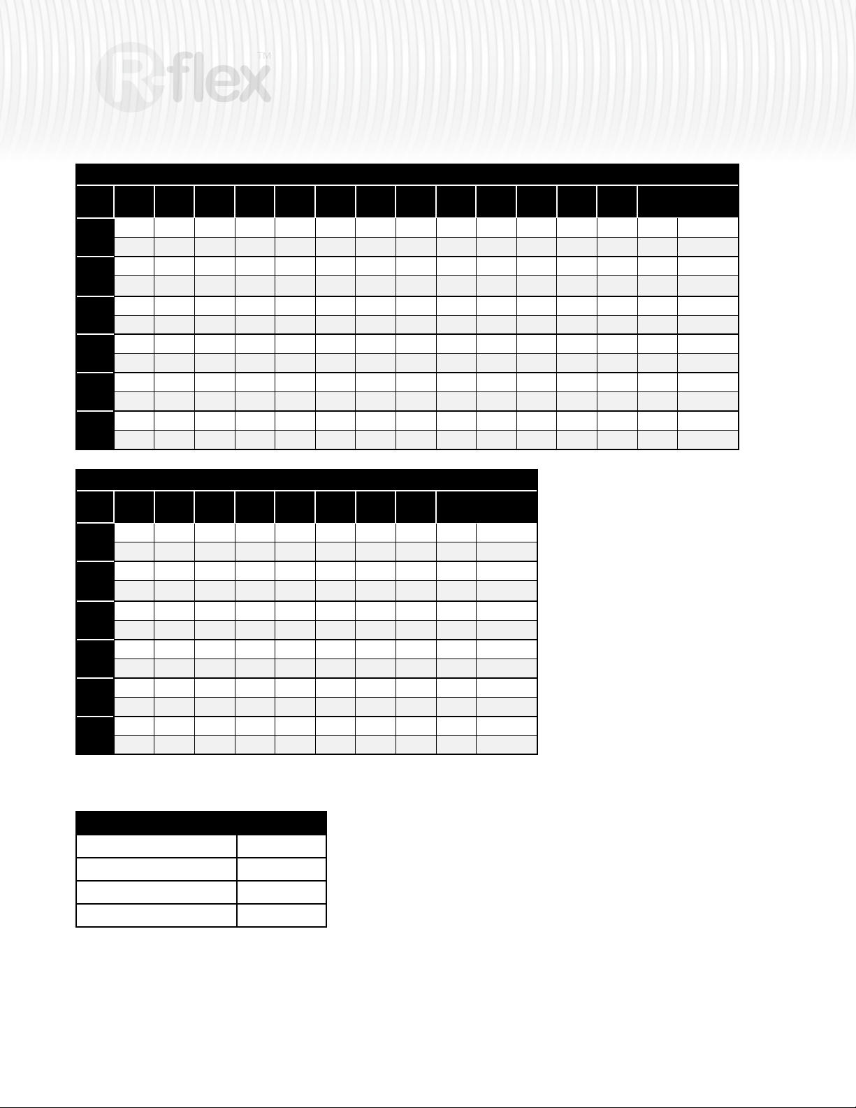
90 mm R-flex Single, Pressure Drop per 100' (3.22" Nom. ID)
50.00
55.00
60.00
65.00
70.00
75.00
80.00
°F
(2.49)
(2.74)
0.78
80°
100°
120°
140°
160°
180°
0.93
1.14 1.35 1.57
0.75 0.89 1.04
1.04 1.22 1.43 1.64
0.72
0.85
0.96 1.14 1.32
0.69
0.82
0.90 1.07 1.25
0.67
0.80
0.86 1.02 1.19
0.65
0.78
0.82 0.98 1.14
(2.99)
(3.24)
(3.49)
(3.73)
1.09 1.25 1.43 1.62 1.82 2.03 2.25 2.71 3.22 3.77 4.36 4.98
1.80 2.05 2.32 2.59 2.88 3.19 3.84 4.54 5.29 6.09 6.94
1.20 1.37 1.55 1.74 1.94 2.15 2.60 3.08 3.61 4.17 4.77
1.87 2.11 2.37 2.63 2.91 3.51 4.15 4.85 5.59 6.38
0.99 1.15 1.31 1.49 1.67 1.86 2.07 2.50 2.97 3.48 4.02 4.60
1.53 1.74 1.97 2.20 2.45 2.72 3.27 3.88 4.53 5.23 5.96
0.96 1.11 1.27 1.44 1.62 1.80 2.00 2.42 2.88 3.37 3.90 4.46
1.44 1.64 1.85 2.08 2.32 2.56 3.09 3.67 4.29 4.95 5.65
0.93 1.08 1.23 1.40 1.57 1.75 1.94 2.35 2.80 3.28 3.80 4.35
1.37 1.56 1.77 1.98 2.21 2.44 2.95 3.50 4.09 4.73 5.40
0.91 1.05 1.20 1.36 1.53 1.71 1.90 2.30 2.73 3.20 3.71 4.25
2.31 1.50 1.70 1.90 2.12 2.35 2.84 3.37 3.94 4.55 5.21
(3.98)
85.00
(4.23)
90.00
(4.48)
100
(4.98)
110
(5.48)
120
(5.97)
130
(6.47)
140
(6.97)
27
GPM
(ft/sec)
100% Water
50% Water/Glycol
100% Water
50% Water/Glycol
100% Water
50% Water/Glycol
100% Water
50% Water/Glycol
100% Water
50% Water/Glycol
100% Water
50% Water/Glycol
110 mm R-flex Single, Pressure Drop per 100' (3.94" Nom. ID)
90
100
110
120
130
140
150
°F
(3.00)
(3.33)
0.86
80°
100°
120°
140°
160°
180°
1.03
1.23 1.47 1.74
0.82 0.99 1.17
1.12 1.34 1.59 1.86
0.78
0.95
1.04 1.25 1.48
0.76
0.92
0.98 1.18 1.40
0.74
0.89
0.93 1.13 1.33
0.72
0.87
0.90 1.08 1.28
(3.66)
(4.00)
(4.33)
(4.66)
(4.99)
1.23 1.43 1.66 1.89 2.14 2.83 3.61
2.03 2.34 2.66 3.01 3.95 5.00
1.37 1.58 1.81 2.05 2.71 3.46
2.14 2.44 2.76 3.62 4.60
1.13 1.32 1.53 1.74 1.98 2.62 3.34
1.73 2.00 2.28 2.57 3.39 4.31
1.09 1.28 1.48 1.69 1.92 2.54 3.23
1.64 1.89 2.15 2.44 3.21 4.08
1.06 1.24 1.44 1.64 1.86 2.47 3.15
1.56 1.80 2.06 2.33 3.07 3.90
1.03 1.21 1.40 1.60 1.82 2.41 3.08
1.50 1.73 1.98 2.24 2.96 3.77
175
(5.83)
Pressure drop through R-flex fittings
Equivalent ft. R-flex
Coupling 1.0
Elbow 5.0
Tee-Run 1.0
Tee-Branch 3.3
200
(6.67)
GPM
(ft/sec)
100% Water
50% Water/Glycol
100% Water
50% Water/Glycol
100% Water
50% Water/Glycol
100% Water
50% Water/Glycol
100% Water
50% Water/Glycol
100% Water
50% Water/Glycol
Page 28
28
insulated piping system
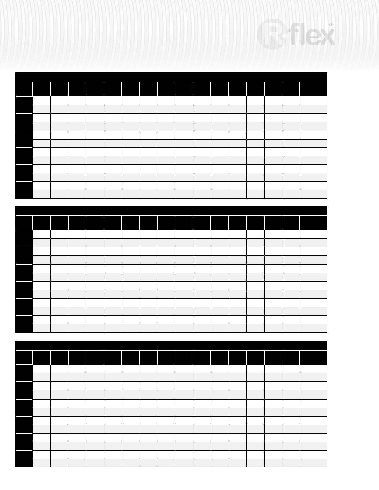
1" R-flex Dual, Pressure Drop per 50' (0.86" Nom. ID)
2.50
3.00
3.50
4.00
4.50
5.00
°F
(1.36)
(1.64)
1.21
80°
100°
120°
140°
160°
180°
1.66
1.20 2.23 3.36
1.14 1.56 2.05
1.71 2.34 3.04 3.81
1.08
1.49
1.56 2.13 2.77
1.04
1.43
1.45 1.97 2.57
1.00
1.38
1.35 1.85 2.41
0.97
1.33
1.29 1.76 2.30
(1.91)
(2.18)
(2.46)
(2.73)
2.17 2.74 3.36 4.04 4.78 5.57 6.42 7.31 9.26 11.40 13.75 16.29 19.02
4.28 5.22 6.24 7.34 8.50 9.75 11.06 13.89 17.00 20.38 24.02 27.92
2.29 3.18 3.83 4.53 5.28 6.08 6.94 8.79 10.84 13.08 15.51 18.11
4.66 5.57 6.56 7.61 8.74 9.92 12.50 15.32 18.39 21.71 25.26
1.95 2.47 3.04 3.66 4.33 5.05 5.82 6.64 8.42 10.39 12.54 14.88 17.39
3.48 4.26 5.10 6.01 6.99 8.03 9.13 11.51 14.13 16.99 20.07 23.37
1.87 2.37 2.92 3.51 4.16 4.86 5.60 6.39 8.11 10.02 12.10 14.36 16.79
3.23 3.96 4.75 5.61 6.52 7.50 8.53 10.77 13.24 15.93 18.83 21.95
1.80 2.29 2.82 3.40 4.02 4.70 5.42 6.19 7.86 9.71 11.73 13.93 16.29
3.04 3.73 4.48 5.29 6.16 7.08 8.06 10.19 12.54 15.09 17.86 20.83
1.75 2.22 2.73 3.30 3.91 4.56 5.27 6.01 7.64 9.44 11.42 13.56 15.87
2.90 3.56 4.28 5.06 5.89 6.78 7.72 9.76 12.02 14.48 17.14 20.00
5.50
(3.00)
6.00
(3.28)
6.50
(3.55)
7.00
(3.82)
8.00
(4.37)
9.00
(4.91)
10.00
(5.46)
11.00
(6.01)
12.00
(6.55)
GPM
(ft/sec)
100% Water
50% Water/Glycol
100% Water
50% Water/Glycol
100% Water
50% Water/Glycol
100% Water
50% Water/Glycol
100% Water
50% Water/Glycol
100% Water
50% Water/Glycol
32 mm R-flex Dual, Pressure Drop per 50' (1.15" Nom. ID)
5.00
5.50
6.00
6.50
7.00
8.00
9.00
°F
(1.96)
1.85
80°
2.89 3.39 3.93
1.75 2.07 2.41
100°
2.57 3.02 3.51
1.67
120°
2.35 2.77 3.21
1.60
140°
2.18 2.58 2.99
1.55
160°
2.06 2.43 2.82
1.50
180°
1.96 2.31 2.69
(2.16)
(2.36)
(2.55)
(2.75)
(3.14)
2.19
2.55 2.93 3.34 4.22 5.20 6.26 7.41 8.65 9.98 11.38 12.87 14.44 16.09
4.50 5.10 6.40 7.83 9.37 11.04 12.82 14.72 16.73 18.85 21.08 23.42
2.77 3.16 4.00 4.93 5.95 7.05 8.23 9.49 10.84 12.26 13.76 15.34
4.02 4.47 5.74 7.04 8.44 9.96 11.58 13.31 15.14 17.07 19.11 21.25
1.97
2.30 2.65 3.02 3.83 4.72 5.70 6.75 7.89 9.11 10.40 11.77 13.22 14.74
3.69 4.19 5.28 6.48 7.78 9.19 10.70 12.30 14.01 15.81 17.71 19.70
1.90
2.21 2.55 2.91 3.69 4.55 5.49 6.51 7.61 8.79 10.04 11.37 12.77 14.24
3.44 3.91 4.94 6.06 7.29 8.61 10.03 11.55 13.16 14.86 16.65 18.53
1.83
2.14 2.46 2.81 3.57 4.40 5.32 6.31 7.38 8.52 9.74 11.03 12.39 13.83
3.25 3.69 4.66 5.73 6.90 8.16 9.51 10.95 12.48 14.10 15.81 17.61
1.78
2.07 2.39 2.73 3.47 4.28 5.17 6.14 7.18 8.30 9.48 10.74 12.07 13.47
3.10 3.53 4.46 5.48 6.60 7.81 9.11 10.50 11.97 13.53 15.18 16.90
(3.54)
10.00
(3.93)
40 mm R-flex Dual, Pressure Drop per 50' (1.43" Nom. ID)
7.00
8.00
9.00
10.00
11.00
12.00
13.00
°F
(1.78)
(2.03)
1.18
80°
100°
120°
140°
160°
180°
1.49
1.83 2.29 2.80
1.12 1.41 1.74
163 2.05 2.51 3.00
1.06
1.35
1.49 1.88 2.30
1.02
1.30
1.39 1.75 2.15
0.99
1.25
1.31 1.65 2.03
0.96
1.22
1.25 1.58 1.94
(2.28)
(2.54)
(2.79)
(3.05)
1.83 2.21 2.61 3.05 3.51 4.00 4.52 5.07 5.65 6.25 6.89 7.55 11.24
3.35 3.94 4.57 5.24 5.96 6.71 7.50 8.32 9.19 10.09 11.02 16.24
2.09 2.49 2.89 3.33 3.80 4.30 4.83 5.38 5.95 6.56 7.19 10.73
3.54 4.11 4.72 5.37 6.05 6.77 7.53 8.31 9.14 9.99 14.77
1.66 2.00 2.37 2.77 3.19 3.64 4.12 4.63 5.16 5.71 6.30 6.90 10.31
2.76 3.26 3.79 4.36 4.96 5.59 6.26 6.96 7.70 8.46 9.26 13.71
1.60 1.93 2.28 2.67 3.08 3.51 3.98 4.46 4.98 5.51 6.08 6.67 9.97
2.58 3.05 3.55 4.08 4.65 5.24 5.87 6.54 7.23 7.95 8.70 12.91
1.55 1.86 2.21 2.58 2.98 3.40 3.85 4.33 4.83 5.35 5.90 6.47 9.68
2.44 2.88 3.36 3.86 4.40 4.97 5.57 6.20 6.86 7.55 8.27 12.28
1.50 1.81 2.15 2.51 2.90 3.31 3.75 4.21 4.70 5.21 5.74 6.30 9.44
2.33 2.76 3.21 3.70 4.22 4.76 5.34 5.94 6.58 7.24 7.93 11.80
(3.30)
14.00
(3.55)
11.00
(4.32)
15.00
(3.81)
12.00
(4.71)
16.00
(4.06)
13.00
(5.11)
17.00
(4.31)
14.00
(5.50)
18.00
(4.57)
15.00
(5.89)
19.00
(4.82)
16.00
(6.29)
20.00
(5.08)
17.00
(6.68)
25.00
(6.34)
GPM
(ft/sec)
100% Water
50% Water/Glycol
100% Water
50% Water/Glycol
100% Water
50% Water/Glycol
100% Water
50% Water/Glycol
100% Water
50% Water/Glycol
100% Water
50% Water/Glycol
GPM
(ft/sec)
100% Water
50% Water/Glycol
100% Water
50% Water/Glycol
100% Water
50% Water/Glycol
100% Water
50% Water/Glycol
100% Water
50% Water/Glycol
100% Water
50% Water/Glycol
Page 29
insulated piping system
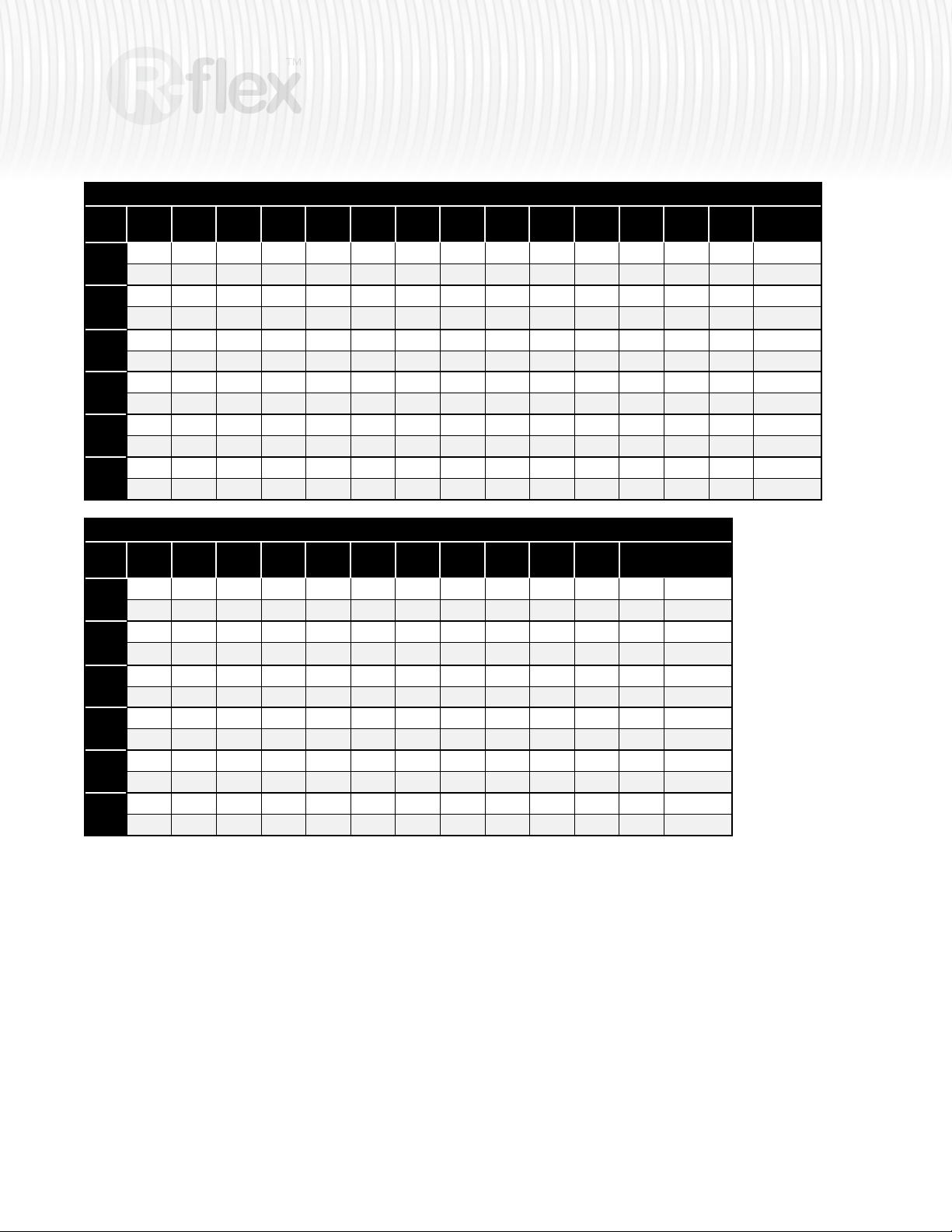
50 mm R-flex Dual, Pressure Drop per 50' (1.79" Nom. ID)
11.00
12.00
13.00
14.00
15.00
16.00
17.00
°F
(1.78)
(1.94)
0.90
80°
100°
120°
140°
160°
180°
1.04
1.37 1.59 1.82
0.85 0.99 1.14
1.23 1.43 1.64 1.86
0.81
0.95
1.13 1.31 1.50
0.78
0.91
1.05 1.22 1.41
0.75
0.88
0.99 1.16 1.33
0.73
0.86
0.95 1.10 1.27
(2.11)
(2.27)
(2.43)
(2.59)
1.20 1.37 1.55 1.74 1.93 2.14 2.35 2.58 3.84 5.31 7.00 8.89
2.07 2.33 2.60 2.88 3.18 3.49 3.81 5.61 7.70 10.07 12.72
1.30 1.47 1.65 1.84 2.03 2.24 2.45 3.65 5.07 6.68 8.50
2.09 2.34 2.60 2.87 3.15 3.45 5.08 6.99 9.17 11.59
1.09 1.25 1.41 1.58 1.76 1.95 2.15 2.35 3.51 4.87 6.42 8.17
1.71 1.93 2.16 2.40 2.65 2.91 3.19 4.71 6.49 8.52 10.79
1.05 1.20 1.36 1.52 1.70 1.88 2.07 2.27 3.39 4.70 6.21 7.91
1.60 1.81 2.02 2.25 2.48 2.73 2.99 4.43 6.11 8.03 10.18
1.02 1.16 1.31 1.47 1.64 1.82 2.01 2.20 3.29 4.57 6.03 7.69
1.51 1.71 1.91 2.13 2.35 2.59 2.83 4.20 5.81 7.64 9.69
0.99 1.13 1.28 1.43 1.60 1.77 1.95 2.14 3.20 4.45 5.88 7.50
1.45 1.63 1.83 2.04 2.25 2.48 2.72 4.03 5.58 7.34 9.32
(2.75)
18.00
(2.92)
19.00
(3.08)
20.00
(3.24)
25.00
(4.05)
30.00
(4.86)
35.00
(5.67)
40.00
(6.48)
29
GPM
(ft/sec)
100% Water
50% Water/Glycol
100% Water
50% Water/Glycol
100% Water
50% Water/Glycol
100% Water
50% Water/Glycol
100% Water
50% Water/Glycol
100% Water
50% Water/Glycol
63 mm R-flex Dual, Pressure Drop per 50' (2.25" Nom. ID)
15.00
20.00
25.50
30.00
35.00
40.00
45.00
°F
(1.53)
(2.04)
0.52
80°
100°
120°
140°
160°
180°
0.86
0.78 1.28 1.88
0.49 0.81 1.21
0.70 1.15 1.70 2.34
0.47
0.78
0.65 1.06 1.57
0.45
0.75
0.60 1.00 1.47
0.43
0.73
0.57 0.94 1.40
0.42
0.71
0.54 0.90 1.34
(2.55)
(3.08)
(3.57)
(4.08)
1.27 1.76 2.31 2.94 3.63 4.38 5.20 6.08 7.02 8.02
2.58 3.37 4.25 5.22 6.27 7.41 8.63 9.93 11.32
1.67 2.20 2.80 3.46 4.18 4.97 5.81 6.71 7.67
3.06 3.86 4.75 5.72 6.76 7.88 9.08 10.36
1.16 1.61 2.12 2.69 3.33 4.02 4.78 5.59 6.46 7.39
2.16 2.83 3.59 4.41 5.32 6.30 7.35 8.47 9.66
1.12 1.55 2.04 2.60 3.22 3.89 4.62 5.41 6.26 7.16
2.03 2.67 3.38 4.16 5.02 5.94 6.94 8.00 9.13
1.08 1.50 1.98 2.52 3.12 3.78 4.49 5.26 6.09 6.97
1.93 2.53 3.21 3.96 4.78 5.66 6.61 7.63 8.72
1.05 1.46 1.93 2.46 3.05 3.69 4.38 5.14 5.94 6.80
1.85 2.43 3.08 3.80 4.59 5.45 6.37 7.35 8.39
(4.59)
50.00
(5.10)
55.00
(5.61)
60.00
(6.13)
65.00
(6.64)
70.00
(7.15)
GPM
(ft/sec)
100% Water
50% Water/Glycol
100% Water
50% Water/Glycol
100% Water
50% Water/Glycol
100% Water
50% Water/Glycol
100% Water
50% Water/Glycol
100% Water
50% Water/Glycol
Page 30
30
insulated piping system
Appendix C pressure test results
Test the nished pipe-work before concealing! The execution and documentation of
the pressure test for the entire piping system is a warranty requirement!
psi
2 Preliminary test
2.1 Operating pressure x 1,5
2.2 After 10 min (restore 2,1)
2.3 After 20 min (restore 2,1)
2.4 After 30min
2.5 After 60 min admissible
pressure drop < 0,6 bar
psi
3 Main test
3.1.1 Beginning
3.1.2 End
3.2 Test pressure
3.3 After120 min
3.4 Remarks admissible
pressure drop < 0,2 bar
Page 31
insulated piping system
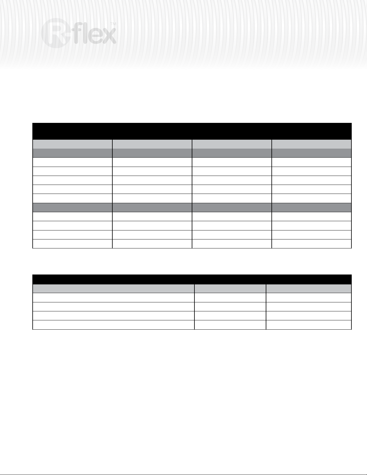
Appendix D installation times
The installation time is highly dependant on local conditions. Obstacles, use of tools and
weather can have a signicant impact on the installation time.
31
Outside casing
d
out
mm mm minutes*
Single (100m)
160 40 60 3
160 50 60 3
160 63 60 4
200 75 75 4
200 110 90 5
Double (100m)
125 1 inch/32mm 40 3
160 40 60 3
200 50 60 3
200 63 60 4
* All installation times are approximate. Transport and digging not included.
Accessories Time Number of Workers
Terminal connections 15-20 min. 1
Tees PEX 30-40 min. 1
Insulation casings 20-30 min. 1
Shrink caps 15 min. 1
* All installation times are approximate. Transport and digging not included.
PEX
d
out
Time per coil Number of Workers
minutes*
Page 32
4500 E. Progress Place
G
R
E
E
N
M
E
C
H
A
N
I
C
A
L
C
O
U
N
C
I
L
Springfield, MO 65803
ph: 417.864.6108
800.276.2419
fax: 417.864.8161
www.wattsradiant.com
Watts Industries - Canada
5435 North Service Road
Burlington, ON L7L-5H7
ph: 888.208.8927
905.332.4090
fax: 888.882.1979
905.332.7068
www.wattscanada.ca
©Watts Radiant 2009 R-flex™ Installation Manual RFLEXMAN071509 Effective Date: 07/15/09 © Watts Radiant 2009
In Canada
 Loading...