

Watts Industries Powers HydroGuard e425, Powers HydroGuard e423, Powers HydroGuard e420 Series, Powers HydroGuard e426, Powers HydroGuard e422 Technical Instructions
...Page 1
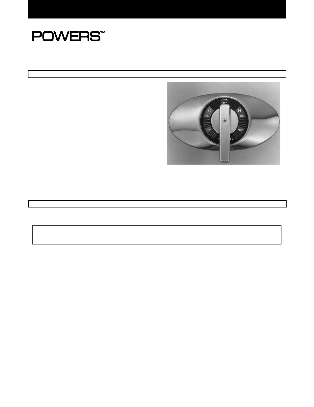
The Series e420 HydroGuard T/P automatically mixes
hot and cold water to deliver blended water within a
specified range. Using an advanced thermal actuator,
the Series e420 quickly compensates for temperature
fluctuations induced by water temperature and pressure
changes. In the event of cold water failure, the thermostatic motor virtually shuts of the flow of hot water.
Featuring heavy, cast-brass construction, all parts of
the e420 Series valve are accessible from the front of
the valve and are corrosion resistant. The unit also features a concealed handle rotation stop to guard against
overadjustment of the handle, and all Series e420
valves open in the cold water position to ensure maximum bather safety and comfort.
The accuracy, reliability and water economy of the
Series e420 HydroGuard make it preferable for applications that require precise, consistent water control:
showers, baths, hospital hydrotherapy and residential
areas.
TECHNICAL INSTRUCTIONS
HydroGuard T/P®Series e420
Thermostatic Valve
Model 1
Valve Construction: Thermostatic mixing valve, with heavy cast bronze body and brass stem. Concealed handle rotation
stop. Available with acrylic handle, chrome-plated metal tri-handle, or ADA-compliant lever handle.
Capacity............................................................................................................................ 5.0 gpm ± .25 @ 45 psi
∆P 50/50 mix
Maximum Hot Water Supply Temperature........................................................................................................ 190°F (88°C)
Minimum Hot Water Supply Temperature.................................................................................. 5°F (2.8°C) above set point
Maximum Operating Pressure....................................................................................................................... 125 psig (862 kPa)
Temperature Ranges
ASSE 1016 Type T/P.............................................................................................................................. 90 - 110°F (32 - 43°C)
ASSE 1016 Type T.................................................................................................................................. 65 - 115°F (18 - 46°C)
Temperature Limit Stop................................................................................................. Adjustable (factory set at 110°F [43°C])
Maximum Static Pressure.............................................................................................................................. 125 psig (862 kPa)
Minimum Flow and Pressure Differential: Minimum Flow
Standard Capacity................................................................................................................................... 1 gpm (3.781 L/min)
Wall Seal Gasket.............................................................................................................................................. Furnished with Dial
Dial Plate..................................................................................................................................... Color-Coded Temperature Scale
Shipping Weight....................................................................................................................................................... 5 lbs. (2.3 kg)
All HydroGuard Series e420 thermostatic mixing valves meet above performance specifications based on typical operating
conditions as stated in ASSE 1016 [45 psi pressure differential, hot water supply between 140°-180°F (60°-82°C), cold water
supply less than 70°F (21°C)].
If your operating conditions vary from those stated in the standard, performance may vary as well. Consult your local
sales representative or a Powers factory engineer to discuss your specific application. All Powers thermostatic mixing
valves perform to the requirements of standards ASSE 1016 and CSA B125.
Many HydroGuard Series e420 valves and shower systems can be selected to meet the Americans with
Disabilities Act (ADA) (see page 4 for details).
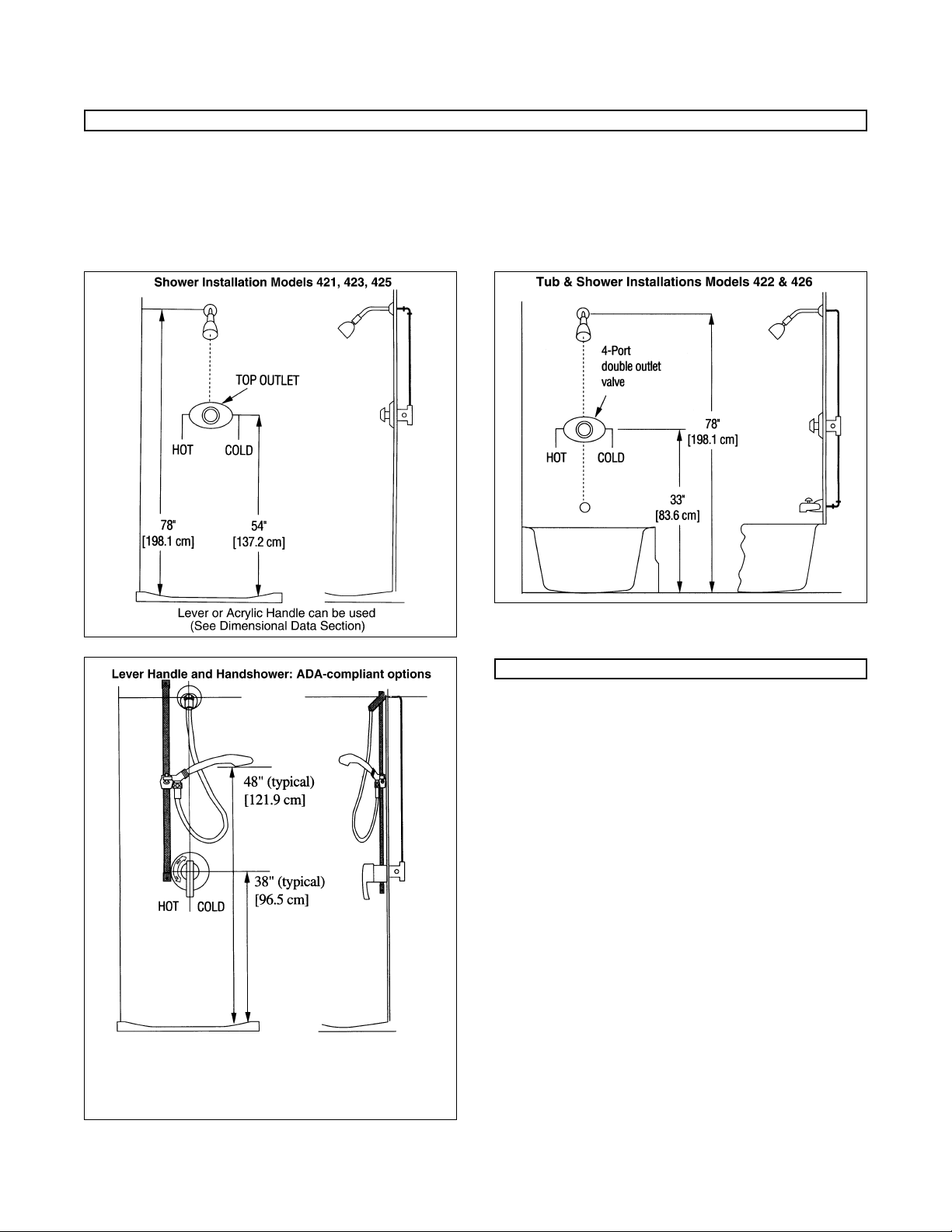
Connections: Type 421, 423, 425 (3-port): 1/2” NPT Inlets Type 422, 426 (4-port): 1/2” NPT Inlets
1/2” NPT Top Outlet 1/2” NPT Top Outlet
3/4”NPT Bottom Outlet
Form TI 420 v5
SPECIFICATIONS
DESCRIPTION
Page 2
TI 420 v5 0515 Page 2
To be sure you order and install the appropriate parts into
your valve, first determine the correct model number and
temperature range of your valve.
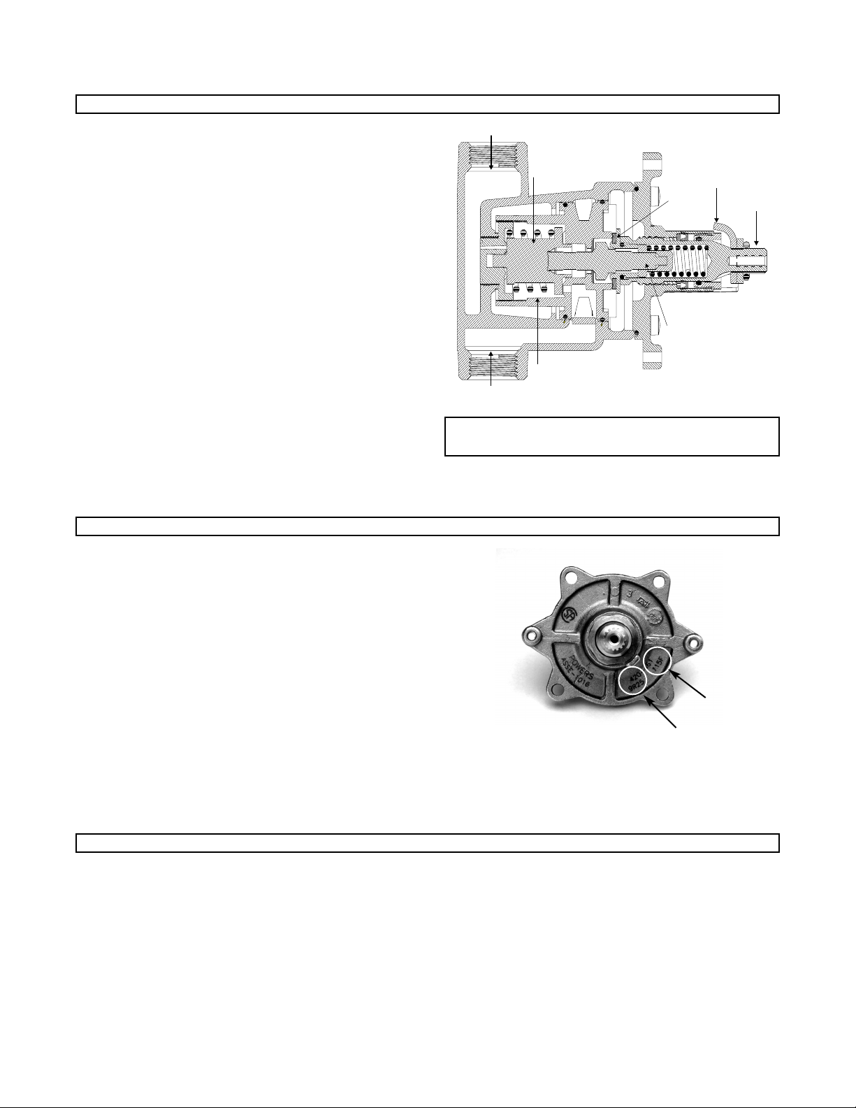
The temperature range of the valve is stamped on a
nameplate (A). In the example, "115" is shown.
The model number is the first digit of the four-digit date
code stamped on the nameplate (B).
In the example, the date code starts with an 9, so the
model number is 9.
Nameplate Stamp
Before installation of any HydroGuard e420 valve:
● Flush all piping thoroughly.
● Rotate the stem (or handle if attached) of
the valve to its full clockwise position (OFF).
Positioning the Valve:
Note the following differences:
3-Port Valves (421, 423, 425): All ports are 1/2" NPT.
INLETS: Piped to hot and cold water supply.
OUTLET: Piped to the showerhead
(see illustration on page 4).
4-Port Valves (422 & 426):
BOTH INLETS AND TOP OUTLET: 1/2" NPT.
BOTTOM OUTLET: 3/4" NPT, and is piped directly to a
diverter-type tub spout (see illustration on page 4).
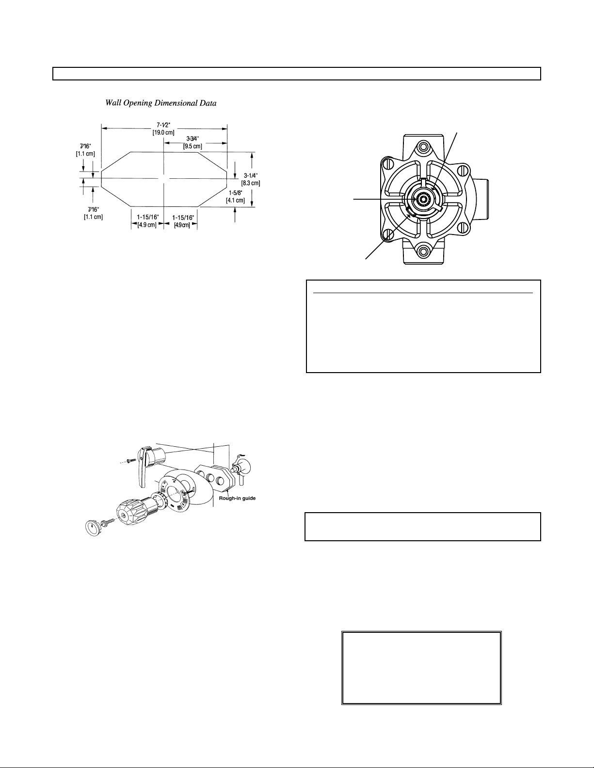
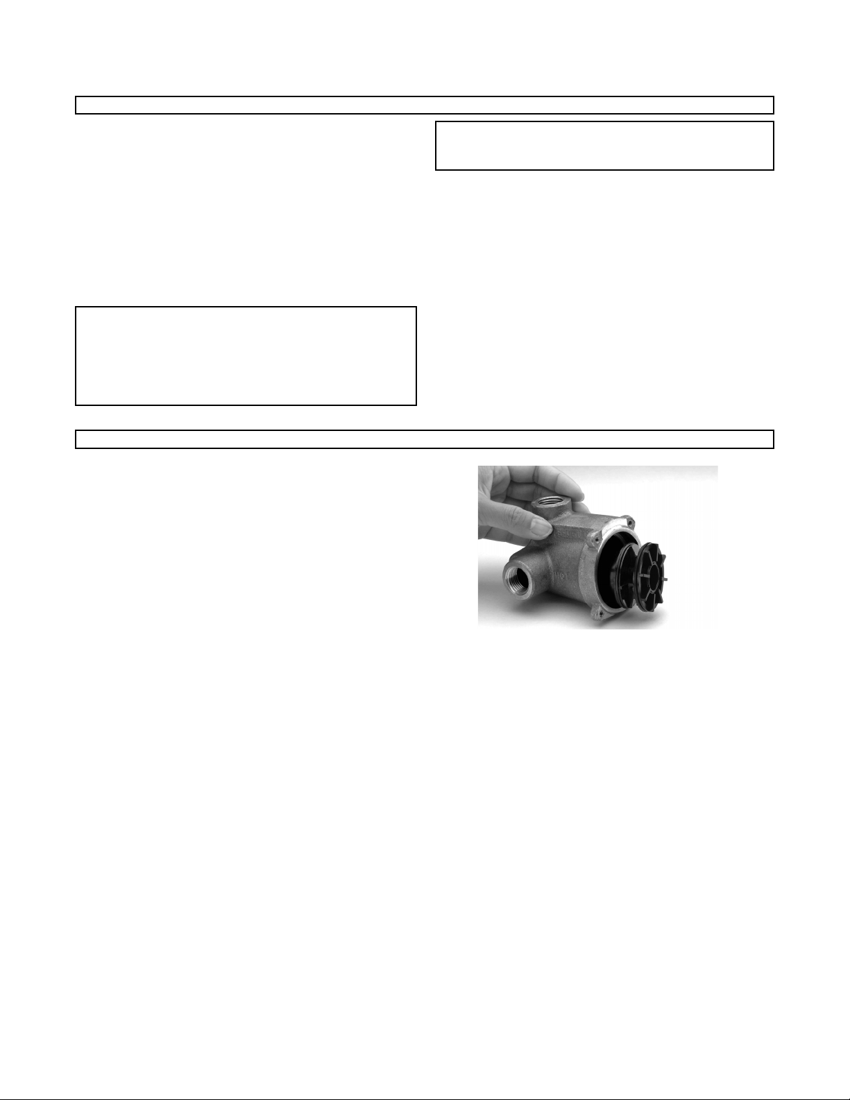
1. Mount the rough-in guide, Powers Part #420-202, to
the mixing valve.
A
B
Hot and cold water enter respective ports in the valve
and mix in a chamber containing an advanced thermal
actuator (refer to cutaway view). This actuator controls
the valve assembly.
Rotating the adjustment handle repositions the shuttle in
the cartridge assembly to produce the desired temperature. The mixed water passes over the shut-off disc to
the outlet. If the hot or cold supply water temperature or
pressure changes, the thermal actuator will contract or
expand. This movement repositions the shuttle to maintain the desired temperature. With the adjustment handle
in full clockwise (OFF) position, the shut-off disc closes
the mixing chamber from the outlet.
A handle rotation stop limits the movement of the control
handle. The standard HydroGuard e420 valve is factory
set to deliver tempered water up to 110°F [43°C] with
equal supply pressures, with hot water temperature
14O°F [60°C], cold water temperature 6O°F [15.6°C].
Note: The handle rotation stop must be adjusted by
the installer.
OPERATION
MODEL IDENTIFICATION
INSTALLATION
Hot Water Supply
Shuttle
Cartridge
Cold Water Supply
Shutoff Disc
Advanced
Thermal
Actuator
Handle Stop
Adjustment
Stem
Page 3
TI 420 v5 0515 Page 3
2. Use rough-in guide to position valve 2-3/4"± l/4"
[7.0 cm ± 0.6 cm] from center line of inlets to face of
finished wall (see Dimensional Data section).
3. Facing front of mixer, connect hot water to left side
(marked HOT) and cold water to right side (marked
COLD). Inlet and outlet connections must be piped correctly for proper operation of valve. Be certain connections are made exactly as described above. If hot and
cold inlets are reversed, valve will not function properly.
Solder Piping
Excessive heat from soldering can damage the internal
parts of the valve. If you use copper tubing, flare fittings
must be installed within 12" (30.5 cm) of the valve or
triple duty checkstops) to protect the valve. If flared fittings cannot be installed, remove the internal parts of the
valve and checkstops before soldering.
Finish Rough-In
4. After finished wall is complete, remove rough-in guide
to allow installation of the dial handle.
5. Peel off backing of dial gasket and attach it to inside
top edge of dial plate. Allow approximately 1/8" [0.3
cm] of gasket to protrude past dial edge.
6. Install dial and handle and secure with screws provided.
Test the System
Before final assembly, test the system and check the
maximum temperature setting.
7. Verify that the valve is in the OFF position (fully clockwise position).
8. Turn on water supply, and then rotate the valve handle
counterclockwise. Water should come through the
spout/showerhead.
Maximum T
emperature Setting/Handle Rotation Stop
The handle rotation setting must be adjusted to limit the
distance the user can rotate the handle towards the full
hot water position.
CAUTION: Any repair or modification of the valve may
affect the high temperature setting. The maximum
temperature setting must be checked by the installer
before use.
9. Remove the valve handle and both splined stops.
10. Adjust the valve to the desired maximum outlet temperature. Install the splined limit stop with its tab against
the bottom of the bonnet stop.
11. Turn the stem clockwise until the water stops. Install
the second splined limit stop with the tab against the
top of the bonnet stop.
12. Replace handle. Repeat steps 8 through 14 until
desired maximum outlet temperature is reached.
Remove handle before final assembly.
CAUTION: Resetting of the splined stop can result in
temperatures higher than 110°F [43°C].
After Rough-In and Testing of System:
Maximum Temperature Setting (Handle Rotation Stop)
CALIFORNIA PROPOSITION 65 WARNING
WARNING: This product contains chemicals
known to the State of California to cause cancer
and birth defects or other reproductive harm.
(California law requires this warning to be given
to customers in the State of California.)
For more information: www.wattsind.com/prop65
INSTALLATION (continued)
Splined
Limit Stop
Stem
Bonnet Stop
Page 4
Final Assembly
13. Place the graphic insert [9] into the dial plate [11], snap
the retaining ring [8] into place in the valve hole.
14. For tri-handle: slide the brass collar over the stem.
Place the tri-handle on stem [22], and secure with
retaining washer [3b] and screw [3c] using the 3/32"
wrench (included). Snap the plug button into place.
15. For lever handle: fit handle (with sleeve) [1] onto stem
and secure in place with screw [2] (provided).
16. For acrylic knob: install insert [7] into knob [6a]. Install
knob onto valve and secure with screw and washers
provided [4 & 51]. Install plug button [3].
EVERY 12 MONTHS:
● Open up the checkstops and check for free movement
of the poppet. To access the checkstops, remove the
valve handle assembly and dial plate.
● Before servicing the valve, turn off the water supply
upstream OR close the optional check-stops. To close
the checkstops, turn the adjustment screw fully clockwise on each checkstop.
● Remove the valve bonnet and rinse all grit and impuri-
ties from the internal components.
● Winterize valves that are used outdoors. Remove and
store the internal components and drain all water from
the valve.
EVERY 3 MONTHS:
● Every three months, check the maximum temperature
setting (handle rotation setting). Refer to steps 8-14 of
the Installation section.
NOTE: Before servicing checkstops or piping, always turn
off the upstream water supply.
Note: When used together, Powers lever handle and handshower meet
ADA compliance standards. For complete ADA-required heights and
other information on installing an ADA-compliant bathing system, refer
to the ADAAG (Americans with Disabilities Act Accessibility
Guidelines).
TI 420 v5 0515 Page 4
INSTALLATION (continued)
PREVENTIVE MAINTENANCE
Page 5
TI 420 v5 0515 Page 5
1. Thermostatic water mixing valves are control devices
which must be cleaned and maintained on a regular
basis. Powers specifies periodic maintenance at least
once a year or immediately after any changes are made
to the plumbing system. Annual cleaning is recommended, however, frequency of cleaning depends on
quality of local water conditions. Refer to the Preventive
Maintenance section for recommended cleaning procedure.
2.
Warning: To prevent injury to the user, it is important
to periodically check the maximum temperature
adjustment on the valve for (1) any sign of motor wear
or (2) motor failure (refer to the Thermostatic Motor
Testing section). The above conditions in the thermostatic motor can cause the valve to pass full hot water.
3. Note: The handle rotation setting must be adjusted to
limit the distance the user can rotate the handle
towards the full hot water position.
4. Quick closing valves may cause damage to the mixing
valve by creating shock waves. When the HydroGuard
supplies tempered water to self-closing and/or solenoid
valves, Powers recommends installing a shock
absorber (Powers Part #460-353) on the discharge line,
which will protect the HydroGuard thermostatic motor
from damage.
5. Position the 420 valve as close as possible to outlet fixture to avoid waste of energy and water (except in
applications where the valve is used as a primary mixing valve).
Adherence to these guidelines and recommendations promotes safe product use and ensures proper
valve performance.
To Disassemble:
1. Turn off hot & cold water supply-stops (required for this retrofit)
2. Remove the handle and trim plate
3. Remove 4 bonnet screws and bonnet assembly
4. Remove all internal components from valve body
5. At this point you should have an empty valve body.
IMPORTANT: After completing any maintenance/repairs,
reset the maximum discharge temperature by resetting the
handle rotation stop as necessary (refer to Maximum
Temperature Setting section).
To Reassemble:
1. Ensure the inside of the valve body is free of deposits
and debris. Clean as necessary.
2. Push the cartridge into the body without the “O” rings
installed. The cartridge should slide in easily, and
bottom out with its large fins just inside the front
surface of the casting. If the cartridge is difficult to
install, or does not go in all the way, remove the
cartridge and clean the the body or remove any
obstructions. Repeat this step until the cartridge
installs easily.
3. Remove the cartridge and install the 2 “O” rings. One is
slightly larger than the other. The larger one goes closest
to the front (fins). Lubricate the “O” rings with silicon
lubricant.
4. Install the cartridge back into the body. The cartridge
should go in until the large fins are just inside the
front surface of the casting (same position as in step 2).
If you cannot push it in all the way due to O-rings, use
bonnet and two (2) screws to force in.
5. Place the wax element into the stem assembly, stem
side first, and place this bonnet-stem-motor assembly
into/onto the valve body. Rotate the bonnet assembly to
line up the bonnet screw holes and reinstall and tighten
the four bonnet screws.
6. With handle, rotate the stem assembly clock-wise, until it
bottoms out on the cartridge. At this point your valve is
in the off position.
7. Turn the hot and cold water supplies back on and verify
there is no leakage.
8. Your valve should now be set properly. Verify proper
operation by rotating the stem from the off position,
counter-clockwise, to the high temperature position.
Verify the temperature does not exceed your desired
maximum temperature. Rotate stem back to the off
position.
9. Replace trim plate and handle.
SAFETY GUIDELINES - ALL MODELS
SERVICING
Page 6
TI 420 v5 0515 Page 6
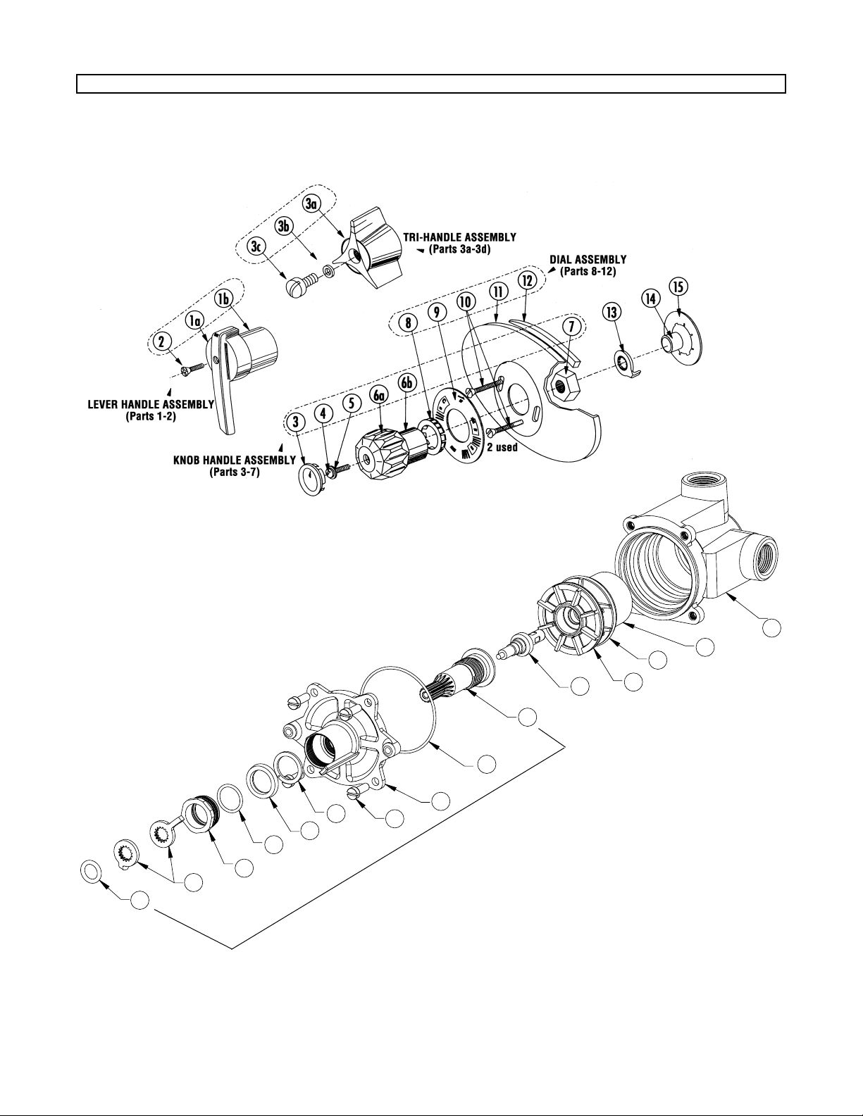
● This parts list is for the E420 Model 1 only.
To be certain you are installing the correct parts, refer to Model Identification on page 2.
● Select Individual Parts from “Part#” column. Select Kits from “Kit#” column.
Item Part Description Part # Qty. Kit # Qty. Individual Parts Material
1-2 Lever Handle Assembly 420-336 1
(Models 8 &9)
1a Lever Handle -- -- 420-336 1 C.P. Zinc
1b Sleeve -- -- 420-336 1 C.P. Brass
2 Lever Handle Screw 410-365 10 1 C.P. Brass
3a-3d Tri-Handle Assembly (All Models 1-9) 410-565 1
3a Tri-Handle 410-191 1 410-565 1 C.P. Brass
3b Washer 046-008K 1 410-565 1 C.R. Steel
3c Screw 030-070 1 410-565 1 Stainless Steel
3d Plug Button (NS) 410-195 1 410-565 1
3-7 Acrylic Handle Assembly 420-337 1
3 Plug Button and Insert 420-314 1 420-337 1 C.P. Brass
4 Handle Screw 8-32 x 3/4” 034-515K 1 420-337 1 C.P. Brass
5 Washer 227-197 1 420-337 1 Neoprene
6a Acrylic Handle Knob -- -- 420-337 1 Acrylic
6b Sleeve 227-196 1 420-337 1 Brass
7 Knob Insert 420-213 2 420-337 1
8-12 Dial Assembly (Models 8 & 9) 420-335 1
8 Retaining Ring 227-166 1 420-335 1 C.P. Brass
9 Dial Graphic Insert (F°) 420-308 1 420-335 1 Aluminum
10 Dial Plate Screws:
(Concealed) 8-32 x 1-1/2” (2) 080-013 2 420-335 1 Brass
11 Dial Plate (Oval)420-166 1 420-335 1 Stainless Steel
12 Dial Gasket 410-284 1 420-335 1 Buna-N
13 Temp. Stop 420-212 2 420-451 -- Stainless Steel
14 O Ring 084-014 1 420-451 -- Buna-N
15 O Ring 047-010 1 420-451 -- Buna-N
16 Packing Gland 420-578 1 420-451 -- Brass
17 Huva Cup 225-404 1 420-451 -- Buna-N
18 Packing Stop Ring 420-508 1 420-451 -- Brass
19 Bonnet Screws 030-887 4 420-451 -- Stainless Steel
20 Bonnet 420-210 1 420-451 -- Brass
21 O-Ring 047-128 1 420-451 -- Buna-N
22 Adjustment Stem 420-139 1 420-451 -- Brass
23 Thermal Actuator -- 1 420-451/453-- Brass/Stainless Steel/EPPM
24 Cartridge Assembly -- 1 420-451/452-- Noryl/Stainless Steel
25 O Ring 047-029 1 420-451 -- Buna-N
26 O Ring 047-129 1 420-451 -- Buna-N
27 Valve Body N/A 1 N/A -- Brass
(Part of 22) Shutoff Disc 420-130 1 420-451 -- EPPM
Bonnet Stem Assembly -- -- 420-454
Soft Part Kit -- -- 420-102
-- Item not available as individual commercial part OR item not available as a commercial kit.
What to look for if:
The maximum temperature cannot be obtained...
a. Lime deposits may have accumulated in the hot water
pipes, restricting the hot water supply.
b. The hot water supply temperature may be too low.
c. The handle rotation setting may be too low. Remove valve
handle, and readjust the handle rotation stop (see Setting
the Handle Rotation Stop).
Flow of water is less than desired…
a. The upstream supply valves may not be fully open.
b. The inlet supply pressure(s) may be low.
c. Lime deposits may have accumulated in cartridge,
restricting water flow.
d. The showerhead may be clogged. Remove and clean.
e. The checkstops may be clogged. Refer to Preventive
Maintenance section and Form #129-028.
The valve opens with hot water flow rather than cold
water flow...
a. The inlet water supplies are connected to the wrong
ports. Remove the valve and reinstall.
The tempered water is too cold, although motor has
been replaced, 0R the hot water temperature is below
115°F...
a. Raise the temperature of the hot water supply.
Flow of water is completely shut off...
a. The upstream supply valves may be completely closed.
b. The hot or cold water supply pressure may have failed.
The HydroGuard 420 valve is designed to close down
upon cold water failure.
c. The checkstops may be closed. Access the checkstops
and open by turning the adjustment screw fully counterclockwise.
TROUBLESHOOTING
PARTS LIST - E420 Model 1
Page 7
TI 420 v5 0515 Page 7
15
13
16
14
17
18
19
20
21
22
23
25
26
24
27
This illustration is for e420 Model 1.
To be certain you install the correct parts, refer to the Model Identification section on page 2.
INCLUDED IN BONNET ASSEMBLY
EXPLODED VIEW - e420 Model 1
Page 8

TI 420 v5 0515 Page 8
© 2005 Powers, a division of Watts Water Technologies, Inc.
USA Phone: 1.800.669.5430 • Fax 1.847.824.0627
Canada Phone: 1.888.208.8927 • Fax 1.888.882.1979
www.powerscontrols.com
Form TI 420 v5 0515 EDP# 6512225 Printed in U.S.A.
CHECKSTOPS
DIMENSIONAL DATA
 Loading...