

Page 1
INSTALLATION, OPERATION AND MAINTENANCE MANUAL
Warning
Please read carefully before proceeding with installation. Failure to follow attached
instructions or operating parameters may lead to the product’s failure.
******************************************************************************************
Save manual for future reference.
Model ZRO-4
ZERO WASTE REVERSE OSMOSIS SYSTEM
System Tested and certified by NSF
International against NSF/ANSI Standard
58 for the reduction of the claims specied
on the performance data sheet.
Watts Premier, Inc. 8716 W Ludlow Drive Suite #1 Peoria, AZ 85381
Phone: 800-752-5582 www.wattspremier.com Fax: 623-866-5666
#199229 Manual Date: 10/26/11
System Tested and certified by WQA
against NSF/ANSI Standard 58 for the
reduction of the claims specied on the
performance data sheet.
Page 2

Thank you for your purchase of a state of the art Watts Premier Zero Waste Reverse Osmosis (RO) water treatment
system. Water quality concerns are quickly becoming more of a focus for the public. Lately you may have heard about
contaminants in the drinking water, such as arsenic, perchlorate, chromium, cryptosporidium or Giardia. There may also
be some local water issues in your area such as high levels of lead, radium and copper. This Watts Premier water treatment
system has been designed and tested to provide you with high quality water for years to come. The following is a brief
overview of the system.
Your Zero Waste Reverse Osmosis System:
Osmosis is the process of water passing through a semi permeable membrane in order to balance the concentration of
contaminants on each side of the membrane. A semi permeable membrane is a barrier that will pass some particles like clean
water, but not other particles like arsenic and lead.
Reverse osmosis uses a semi permeable membrane; however, by applying pressure across the membrane, it concentrates
contaminants (like a strainer) on one side of the membrane, producing crystal clear water on the other. This is why RO
systems produce both clean drinking water and waste water that is ushed from the system. In an effort to provide high
quality drinking water while meeting the water supply challenges across the country, Watts Premier has patented this Zero
Waste RO system. This Zero Waste RO is 100% effective in providing high quality reverse osmosis drinking water while
not wasting any water down the drain.
This Zero Waste reverse osmosis system also utilizes carbon block ltration technology, and can therefore provide a higher
quality drinking water than carbon ltration systems alone.
Your system is a four stage RO which is based upon separate treatment segments within the one complete water ltration
system. These stages are as follows:
Stage 1 – Sediment lter, recommended change 6 months.
The rst stage of your RO system is a ve micron sediment lter that traps sediment and other particulate matter
like dirt, silt and rust which affect the taste and appearance of your water.
Stage 2 – Carbon lters, recommended change 6 months.
The second stage contains a 5 micron carbon block lter. This helps ensure that chlorine and other materials that
cause bad taste and odor are greatly reduced.
Stage 3- Membrane, recommended change 2-5 years.
Stage three is the heart of the reverse osmosis system, the RO membrane. This semi permeable membrane will
effectively take out TDS, Sodium and heavy metals such as arsenic, copper, and lead, as well as Cysts, such as
Giardia and cryptosporidium. Because the process of making this high quality drinking water takes time, your RO
water treatment system is equipped with a storage tank.
Stage 4- Carbon inline lter, recommend change 6 - 12 months.
The nal stage is an inline granular activated carbon (GAC) lter. This lter is used after the water storage tank,
and is used as a nal polishing lter.
System Maintenance
Just because you can not taste it, does not mean that it is not there. Contaminants such as lead, chromium and arsenic (to
name a few) are undetectable to the taste. Additionally, over time if you do not replace the lter elements, other bad tastes
and odors will be apparent in your drinking water.
This is why it is important to change out your lters at the recommended intervals as indicated in this system manual. When
replacing the lter elements, pay special attention to any cleaning instructions. Should you have any further questions please
refer to our website at www.wattspremier.com or call our customer service dept. at 1-800-752-5582.
Page 3

** Before installation, please take a moment to ll out the warranty card on page 21-22.
Thank you for your purchase of a Watts Zero Waste Reverse Osmosis system. With proper installation
and maintenance, this system will provide you with high quality water for years to come. All of Watts
water enhancement products are rigorously tested by independent laboratories for safety and reliability.
If you have any questions or concerns, please contact our customer service department at
1-800-752-5582 (outside USA 480-675-7995).
Table of Contents
Operational Parameters ........................................................................................................................ 4
Contents of Reverse Osmosis System .................................................................................................. 4
Tools Recommended For Installation .................................................................................................... 4
Important Notice .................................................................................................................................... 5
Drill a Hole for the Faucet in a Porcelain Sink ....................................................................................... 5
Punch a Hole for the Faucet in a Stainless Steel Sink .......................................................................... 5
Installation of Faucet ............................................................................................................................. 6
Connect Blue Tube from the RO to the Fuacet ..................................................................................... 6
Adapt-a-Valve Installation ...................................................................................................................... 7
Connect the Green and Black Tubing.................................................................................................... 7
Mounting the RO Module....................................................................................................................... 7
Tank Ball Valve Installation ................................................................................................................... 7
Blue Tube Connection (From the RO Module to TANK) ........................................................................ 8
Start up Instructions............................................................................................................................... 8
6 Month System Maintenance ............................................................................................................... 9
Annual Maintenance ............................................................................................................................ 10
Membrane Maintenance .......................................................................................................................11
Check Air Pressure in the Tank ........................................................................................................... 12
Trouble Shooting ................................................................................................................................ 12
Faucet Adjustment ............................................................................................................................... 13
Performance Data Sheet ..................................................................................................................... 14
Arsenic Fact Sheet .............................................................................................................................. 15
Flow Chart ........................................................................................................................................... 16
Parts List.............................................................................................................................................. 17
Other Products by Watts Premier ................................................................................................... 18-20
Warranty Registration ..................................................................................................................... 21-22
Service Record .................................................................................................................................... 23
Warranty .............................................................................................................................................. 24
3
Page 4
Operational Parameters
Installation must comply with State and local plumbing regulations. This system is to be installed
to treat cold water only.
Operating Temperatures: Maximum 100°F (37.8°C) Minimum 40°F (4.4°C)
2
Operating Pressure: Maximum 85 psi (6.0 kg/cm
) Minimum 40 psi (2.80 kg/cm
pH Parameters: Maximum 11 Minimum 2
Iron: Maximum 0.2 ppm
TDS (Total Dissolved Solids) < 1800 ppm
Turbidity < 5 NTU
Hardness: Recommended hardness not to exceed 10 grains per gallon, or 170ppm. System will
operate with hardness over 10 grains but the membrane life may be shortened. Addition of a water
softener may lengthen the membrane life.
Water Pressure: The operating water pressure in your home should be tested over a 24 hour period
to attain the maximum pressure. If the incoming water pressure is above 85 psi a pressure regulator
is recommended and if over 100 psi then a pressure regulator is required.
Copper Tubing: Reverse Osmosis water should not be run through copper tubing as the purity
of the water will leach copper causing an objectional taste in water and pin holes may form in the
tubing. Watts Premier supplies speciality lters (part number 107008) that can be used if copper
tubing follows the Reverse Osmosis unit. Be sure to follow any state or local regulations during
installation.
2
)
* Note: RO unit must be installed a minimum of 25 Pipe feet from water heater *
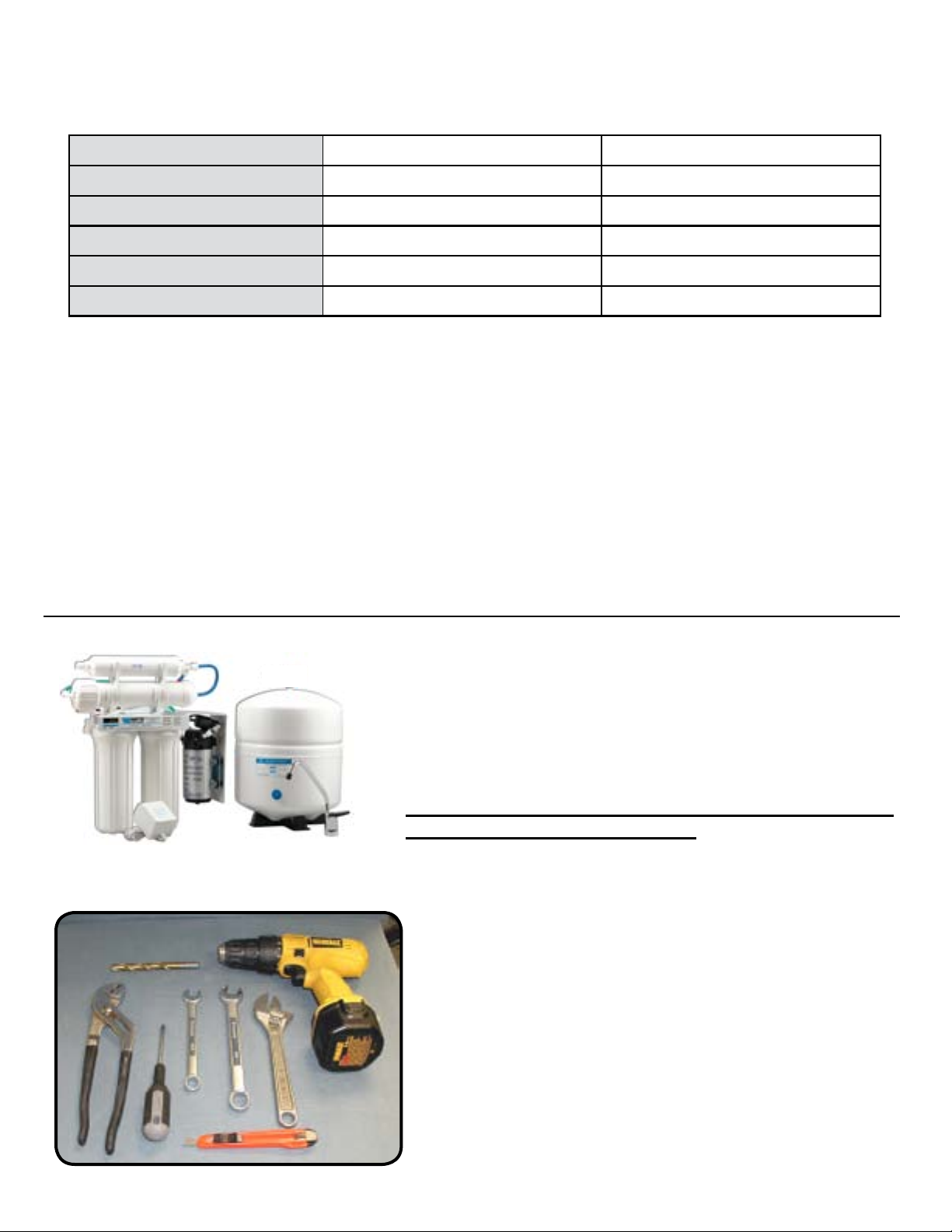
System includes:
RO module, 24 volt Pump, 3 gal Storage tank, Long
reach faucet, Manual, Warranty Card, Parts Bag (2 Water
line tting valves, 2 Washers,Transformer, 2 Mounting
screws, 1 Teon tape roll, 2 Brass inserts, 2 Plastic
sleeves, 1 Ball valve)
If any of the items are missing please contact Watts at
1-800-752-5582 prior to installing
Tools recommended for installation
7/16” Drill bit for faucet
Channel lock pliers
Phillips Screw Driver
1/2” - 5/8” Open End Wrench
Adjustable Wrench
Sharp knife
Electric Drill
4
Page 5
***IMPORTANT NOTICE***
Not recommended for use on homes equipped with tankless water heaters. Contact Watts Premier for
specic details regarding this unit and tankless water heaters.
System was tested in a laboratory setting utilizing a hot water heater of 40 gallons set at 120º F.
Performance may vary if your heater is smaller than 40 gallons or set above 120º F, contact the
manufacturer for additional details.
System should not be used on homes equipped with a backow prevention on the hot water heater.
This device is 100% efcient, as no water is lost to drain in the production of the RO water.
Drill a Hole for the Faucet in a Porcelain Sink
Note:
Step 1
Step 2
Step 3
Step 4
Most sinks are pre drilled with 1 ½” or 1 ¼” diameter hole that you can use for your
RO faucet. (If you are already using it for a sprayer or soap dispenser, see step 1)
Porcelain sinks are extremely hard and can crack or chip easily.
Use extreme caution when drilling. Premier accepts no responsibility for
damage resulting from the installation of faucet.
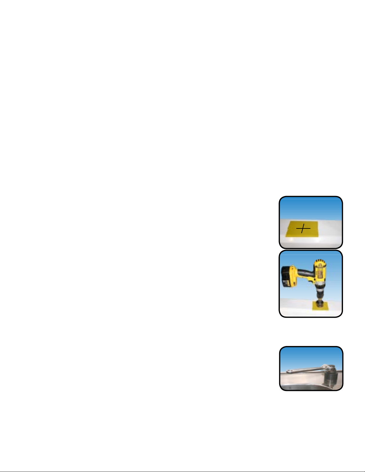
Determine desired location for the RO faucet on your sink and place
a piece of masking tape on over where the hole is to be drilled. Mark
the center of the hole on the tape.
Using a variable speed drill set on the slowest speed, drill a
hole through both porcelain and metal casing of sink at the marked
center of the desired location. Use lubricating oil or liquid soap to keep
the drill bit cool (If drill bit gets hot it may cause the porcelain to crack
or chip).
Using a 1/2” hole saw, proceed to drill the large hole. Keep drill speed
on the slowest speed and use lubricating oil or liquid soap to keep the
hole saw cool during cutting.
Make sure the surroundings of the sink are cooled before mounting the
faucet to the sink after drilling and remove all sharp edges.
1
/8“ pilot
Punch a Hole for the Faucet in a Stainless Steel Sink
Note:
Step 5
If mounting faucet to a Stainless Steel Sink you will need a 1/2”
minimum hole punch. The faucet opening should be centered
between the back splash and the edge of the sink, ideally on the
same side as the vertical drain pipe.
Drill a ¼” pilot hole. Use a 1/2” Hole Punch and an adjustable wrench
to punch the hole in the sink.
The faucet can now be installed.
5
Page 6
Installation of Faucet
Step 6
Step 7
Step 8
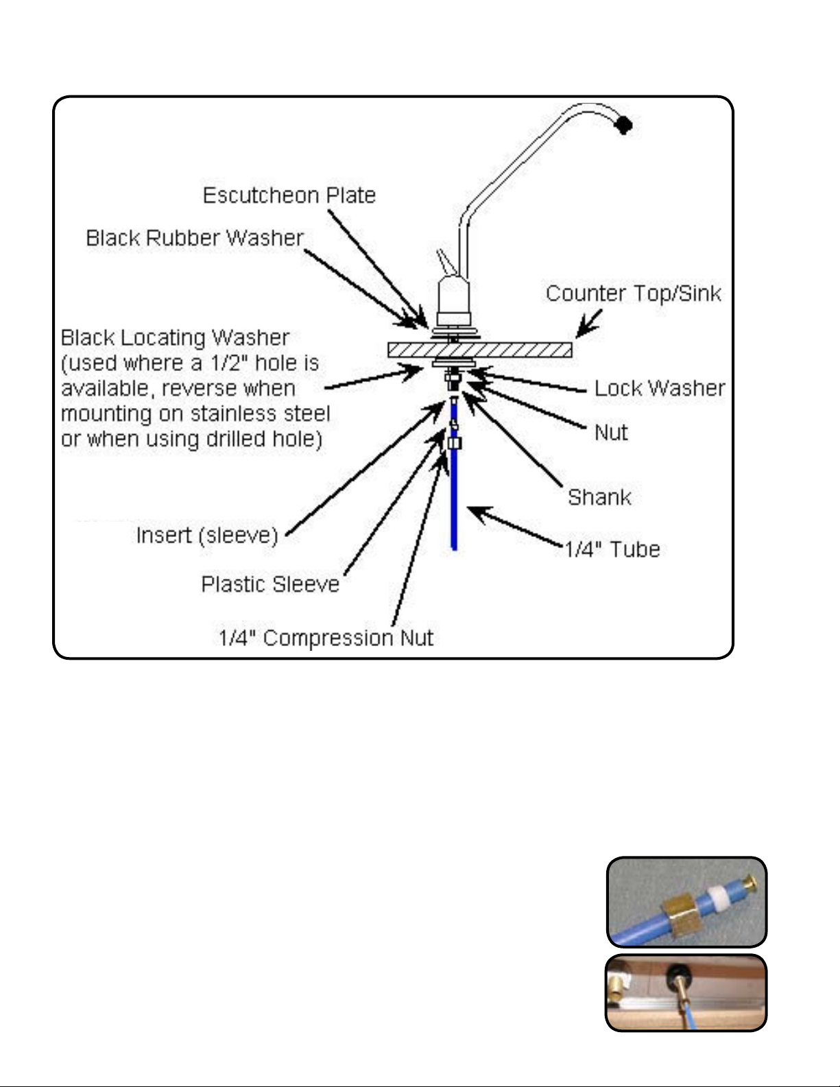
Place the escutcheon chrome plate and the black rubber washer on the faucet shank.
(Parts found in faucet parts bag).
Insert the faucet shank through the hole in sink and let it rest on the sink top.
From the underside of the sink, slide on the locating washer, lock washer and brass
nut onto the shank. Check orientation of faucet then tighten brass nut securely.
Connect Blue Tube from the RO to the Faucet
Step 9
Step 10
Locate the blue 1/4” tube attached to the RO module labeled
“Faucet”. Remove a brass nut, plastic sleeve and brass insert from
the parts bag. To assemble, place the brass nut on the blue tube
rst, then the sleeve (small tapered end of sleeve must point to the
end of tube) and then push the brass insert all the way into the end
of the tube. (See Picture)
Insert the blue tube into the end of the faucet shank and use a
wrench to tighten the brass nut securely.
6
Page 7
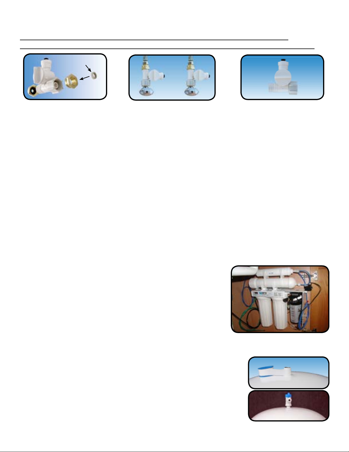
Adapt-a-Valve Installation
Water supply line to the system must be from the cold water supply line only. Hot water
connection is used for rinse water return and must be connected for system to function correctly.
* Washer
Conguration for 3/8”
(With Brass Fittings)
* Insert White Washer
Step 11
Step 12
Turn off the cold and hot water supply to the faucet by turning the angle stop valve completely
off.
Attach the Adapt-a-Valves as illustrated in the three photos above, choosing the
conguration that ts your plumbing.
Do not use teon tape with the Watts Adapt-a-Valve.WARNING:
Hot
(Return)
Cold
(Supply)
Conguration for 1/2”
(Without Brass Fittings)
Connect the Green and Black Tubing
Step 13 Locate the 1/4” green tubing attached to the RO system. Insert the open end of the green
1/4” tube into the open 1/4” quick connect tting on the COLD water feed adapta-a-valve
making sure the tube is pushed in all the way to the tube stop. Repeat the procedure to
connect black tubing from the RO module to the hot water, return adapt-a-valve.
Mounting the RO Module
Step 14
Determine the best location for the RO Module to be
mounted and allow for future system maintenance. Use
a Phillips screwdriver and secure the screws 5 3/4” apart
and 16” from the bottom of the cabinet.
Tank Ball Valve Installation - Part#: 134018
Step 15
Step 16
Teon tape must be applied in a clockwise direction. Wrap
(7 to 12 turns) around the male pipe threads (MPT) on the
stainless steel tting on top of the tank.
Thread the quick connect ball valve (supplied in the parts bag)
onto the stainless steel connector on the tank.
Note: Do not over-tighten plastic connections.
7
Page 8

Blue Tube Connection (From The RO Module To TANK)
Step 17
Note: Set the blue ball valve knob in-line with the blue tube, this is the “open” position.
Position tank in desired location. Stand it upright or lay it on
its side (using the black plastic stand). Measure the blue tube
(marked “TANK”) from the RO module to the tank and cut it to
length leaving a straight, square edge. Insert the tube into the
quick connect tting on the tank ball valve. Make sure the tube
is pushed in all the way to the tube stop.
Start up Instructions
Warning: To prevent the possibility of electrical shock, clean up any water on
cabinetooranddryallwaterfromoutsideofROunit.
Step 1 Turn on the incoming hot and cold water angle stop valves.
Turn on the water adapt-a-valves.
Check the system for leaks and tighten ttings as
necessary.
Note: Check daily over the next week to ensure no leaks are present.
Step 2 Plug the (24 volt) transformer power cord connector into the RO
system wire harness connector (labeled transformer.)
Step 3 Plug the transformer into the electrical outlet under the sink.
Step 4 Ensure ball valve on tank is open.
Step 5 Open the RO faucet and leave it open until water begins to drip. Then close the faucet.
The tank will take approximately 4 hours to ll.
Note: If no water comes out of the RO faucet after a few minutes check the power
outlet. It is possible that the power outlet you used for the RO unit is controlled
by the garbage disposal switch. To test - Unplug the garbage disposal and ip
the garbage disposal switch to “on” . If the RO pump turns on and water starts to
drip out of the RO faucet you will need to connect the system to a different power
outlet socket.
Note: Water may be cloudy or milky due to air in the system and carbon particles ushing out
of the nal polishing lter. This condition will resolve itself after ushing a couple of
tanks of water.
Step 6
Thisushingprocedureisonlynecessaryaftertheinitialinstallationandafter
replacing the RO membrane.
After the Tank has lled, open the RO Faucet to ush the tank completely. You will know
that the tank is empty when the ow rate from the RO faucet is down to a trickle. Repeat
this step two more times. The fourth tank can be used for drinking. This process should
take approximately 24 hours to complete.
8
Page 9

6 Month System Maintenance - Filter Kit #560038
*Order lters by calling 1-800-752-5582 or buy online at www.wattspremier.com.
Items needed:
√ Stage 1 - Sediment Filter (part #: 104017)
√ Stage 2 - Carbon Block Filter (part #: 101009-White End Caps)
Note:
Step 1
Step 2
Step 4
Step 5
Caution:
The lter wrench pictured (Part # 164003) may be purchased from Watts Premier to aid with
twisting off lter housings but is not required.
Close the ball valve on the RO storage tank and open the RO Faucet.
Turn off the incoming cold water supply to the RO at the adapt-a-valve and unplug the power
transformer from the electrical outlet.
For more leverage you may leave the RO module attached to wall of
cabinet. If you are unable to access the module while it is mounted,
remove it prior to changing lters. Starting with the closest housing
(Stage 1), remove it by turning it clockwise (left), empty water, then
nd
discard lter and repeat for the 2
Clean the lter housings (bowls) with a mild soap solution and rinse
housing (Stage 2).
Loosen
with water. Check O-rings and lubricate with water soluble lubricant.
KY Jelly® or other water based lubricants may be used. Petroleum
sediment
based lubricants (such as Vaseline®) must not be used.
Before re-installing the lter bowls back on to the system, check
O-rings to make sure they are still in place. *
carbon block
Step 6
Insert a new sediment lter (cloth like appearance) into the 1st lter
housing which is the one on the water inlet side (green tubing from
Step 7
the adapt-a-valve) of the RO system and re-install housing.
Insert the new Carbon Block lter (White end caps & plastic netting)
*
into the second lter bowl and re-install housing.
Warning: To prevent the possibility of electrical shock, clean
upanywateroncabinetooranddryallwaterfromoutsideofROunit.
Step 8
Plug the power transformer back into the electric outlet and turn cold water supply on to
the unit at the adapt-a-valve.
Step 9 Close the RO faucet and open the ball valve on the RO storage tank. Your system is ready
for use.
9
Page 10

Annual Maintenance - Filter Kit #560032
Items needed:
√ Stage 1 - Sediment Filter (part #: 104017)
√ Stage 2 - Carbon Block Filter (part #: 101009-White end caps)
√ Stage 4 - 10” Final Polishing lter (part # 560010)
√ 1/2 Cup of hydrogen peroxide or common household bleach - not included in lter kit.
Note:
Step 1
Note:
Step 2
Step 3
Step 4
Step 5
Step 6
Sanitizing of unit is recommended.
Perform steps 1 through 5 in the Six Month System Maintenance (Page 9).
If not sanitizing the system skip to step 8.
Remove the RO membrane from its housing and rest in a clean sanitary place. (Refer to
“Membrane Replacement” section on page 11 for directions on removing the membrane).
Replace cap onto empty membrane housing and re-connect green tubing.
Leaving the lters out, replace stage 2 empty lter housing (hand tight) onto unit. Measure
& pour either 1/2 cup of hydrogen peroxide or common household bleach into the 1st lter
housing (Stage 1) and hand tighten onto unit. Ball valve on RO tank should be open.
With the RO faucet in the closed position turn on the incoming water supply to the system
by turning the adapt-a-valve counter clockwise. Plug in the power transformer back into the
electrical outlet. Wait 1 minute for the unit to pressurize. Turn on the RO faucet and let the
water run for 30 seconds. Turn off the RO faucet and let the unit rest for 2 minutes. Finally,
open the RO faucet and let the water run for 5 more minutes.
Unplug the Power Transformer. Turn off the incoming water supply to the system by turning
the adapt-a-valve clockwise until it stops. Keep the RO faucet open until the storage tank
is completely drained.
Open the membrane housing and re-install the RO membrane while making sure not to kink
the O-rings. (Refer to “Membrane Replacement” section on page 11 for directions on
installing the membrane). Tighten the cap back on the housing and reconnect green tubing.
Step 7
Caution:
Remove lter housings Stage 1 and 2 and empty of water.
Before re-installing the lter bowls back on to the system , check O-rings to make sure
they are still in place and lubricate with water soluble lubricant.
st
Step 8
Insert the new sediment lter (cloth like appearance) into the 1
lter housing which is the one
on the water inlet side (green tubing from the adapt-a-valve) of the RO system and
re-install housing.
Step 9
Insert the new Carbon Block lter (White End Caps) into the 2nd housing and re-install
housing.
Step 10
Remove the nal lter from the two clips. Remove the white nuts from both ends of the lter.
Remove the connectors from both ends (keep and reuse). Discard the old nal lter and
replace with new lter reusing the connectors .
Note: Flow arrow on nal lter must be pointing in the direction of water ow to the RO faucet.
Tip:
This is a good time to check the air pressure in your storage tank. For instructions
please see page 12.
Step 11 Follow Start Up procedure on page 8.Youwillneedtoushahalfagallonofwater
before using the RO water .
10
Page 11

Your reverse osmosis system contains replaceable treatment components that are critical for effective
contaminant reduction. Periodic inspection and following proper system maintenance is critical for
continued performance.
Membrane Maintenance
RO Membranes have a life expectancy between 2 and 5 years, depending on the incoming water
conditions and the amount the RO system is used. This reverse osmosis membrane is critical for
effective reduction of total dissolved solids (TDS). The product water should be tested periodically to
verify that the system is performing satisfactorily.
Normally, a membrane would be replaced during a semiannual or annual lter change. However, if at
any time you notice a reduction in water production or an unpleasant taste in the reverse osmosis
water, it could be time to replace the membrane. Watts Premier recommends replacing the
membrane when TDS reduction falls below 75%.
A water sample may be sent to Watts Premier for a free diagnosis of your membrane
performance.Tosendawatersample,usetwo(2)cleancontainersandll½cupoftapwaterin
onecontainerand½cupofreverseosmosiswaterin2ndcontainer.Clearlylabeleachsample.
Send the samples to the address listed on the cover of this manual attention “Water Samples”.
Watts Premier will test the water and mail or call you with the results.
Step 1
Step 2
Removing the membrane:
Step 1
Step 2
Note:
Step 3
Installing the membrane:
Step 4
Turn off the incoming cold water supply to the RO at the adapt-avalves and unplug the power transformer..
Open the RO Faucet and allow water to drain from the tank until it
is completely empty.
Use a 5/8” wrench to remove the Green Tube tting on the left side
of the horizontal membrane housing (end with one elbow).
Remove the cap from the membrane housing by turning it counter
clockwise to loosen.
A double sided wrench may be purchased from Premier to aid with
loosening the cap / lter housings. (Part # 164003)
Remove membrane housing from the holding clips. Using a pair of
pliers, grip the PVC tube of the RO membrane and pull rmly on the
membrane to remove from the housing and discard.
Lubricate the O-rings on the new membrane with a water soluble
lubricant such as KY Jelly ®. Insert the end with the two black
O-rings rst into the housing.
Loosen
Step 5
Step 6
Step 7
Once membrane has been inserted into the housing you must take
your thumbs and give a rm push to properly seat the membrane.
Replace membrane housing cap and tighten.
After replacing membrane housing into clips, attach the green tube
to the elbow on cap using 5/8” wrench.
Follow the Start Up Instructions on page 8.
11
Page 12

Check Air Pressure in the Tank
Important:
Check air pressure only when tank is empty of water!
Check air pressure in the storage tank when you notice a decrease in available water from
the RO system. Air can be added with a bicycle pump using the schrader valve that is
located on the lower side of the tank behind a blue plastic cap.
Step 1
Turn off the incoming cold water supply to the RO at the adapt-a-valve
clockwise until it stops. (Follow the green tube away from the RO
system to nd the adapt-a-valve.)
Step 2
Open the RO Faucet and allow water to drain from the tank until it is
completely empty.
Tip:
When water from the RO faucet slows to a trickle, with the faucet still in the open
position, you may add air to the tank to purge any left over water, this will ensure that
the tank is completely empty.
Step 3
Once all water in the tank is purged, check air pressure using an air pressure gauge, it
should read between 5 - 7 PSI. (Digital air pressure gauge is recommended)
Trouble shooting
Problem Cause Solution
Low/slow production Excessive air pressure in tank Relieve pressure at schrader valve on tank (set
to 7 psi with the tank empty)
Pump not operating Wiring connection broken (plug 110 AC wall
plug back in at wall and/or reconnect the 24
VAC wire harness connectors)
Replace pump if needed
Fouled membrane Replace membrane
Plugged pre-lters Replace lters
Crimped tubing Check tubes to make sure they are not kinked
Angle stop or water line valve Ensure valves are opened by turning valve
not fully opened handle counter clockwise until it stops
Milky colored water Air in the system Air in the system is a normal occurrence with
initial start up of the RO system. This milky look
will disappear during normal use within 1-2
weeks. If condition reoccurs after lter changes,
drain tank 1 to 2 times.
Faucet Dripping Needs adjustment see page 12
Pump short cycles Ball valve on tank closed Open the ball valve on the top of the tank
Blue tube blocked between Remove kinked/damaged section and replace if
the tank and RO system necessary
Faulty pressure switch Call for technical support
Bowl leaks at the top after Damaged/Dry O-ring Lubricate with water soluble lubricant or replace
changing the lters O-ring as necessary (Do not use Vaseline or
other petroleum based lubricants)
Pump constantly running Electrical fault Call for technical support
Faucet left on Close faucet and let tank ll for 2 to 3 hours
Plugged pre-lters Replace lters
12
Page 13

Adjust Faucet
If the faucet has developed a drip it can be corrected by following the steps outlined below.
Step 1 Remove faucet Spout rst. Position both thumbs on the
back edge of the lever and push forward.
Step 2 Lever will slide forward and completely off of the faucet base.
Step 3 Small brass tee can be turned 1/2 turn, counterclockwise, to adjust
the tension on the black lever. This adjustment may be necessary
to stop slow drips from tip of faucet. You may need to repeat the
process until the faucet does not drip. Brass tee must always end
up facing across body of faucet in order to slide black lever on.
13
Page 14

Performance Data Sheet
ZRO-4 Zero Waste RO
Watts Premier Inc.
8716 W Ludlow Drive Suite #1
Peoria, AZ 85381
480) 675-7995 wpmail@wattsind.com
GENERAL USE CONDITIONS:
1. System to be used with municipal or well water sources treated and tested on regular basis to insure bacteriological safe quality. Do not use
with water that is microbiologically unsafe or unknown quality without adequate disinfection before and after the system. Systems certied for cyst
reduction may be used on disinfected water that may contain lterable cysts.
2. Operating Temperature: Maximum: 100°F (40.5°C) Minimum: 40° (4.4°)
3. Operating Water Pressure: Maximum: 100 psi (7.0kg/cm2) Minimum: 40 psi (2.8kg/cm2)
4. pH 2 to 11
5. Hardness of more than 10 grains per gallon (170 ppm) may reduce TFM membrane life expectancy.
6. Recommend TDS (Total Dissolved Solids) not to exceed 1800 ppm.
RECOMMENDED REPLACEMENT PARTS AND CHANGE INTERVALS:
Depending on incoming feed water conditions replacement time frame may vary.
Change Time Description
6 months: Sediment Pre-lter (104017); Carbon Pre-lters (101009)
12 months Final Carbon lter (100017)
3 to 5 years R.O. Membrane (110009)
This system has been tested according to NSF/ANSI 58 for reduction of the substances below. The concentration of the indicated substances in
water entering the system was reduced to a concentration less than or equal to the permissible limit for water leaving the system as specied in
NSF/ANSI 58. This system has been tested for the treatment of water containing pentavalent arsenic (also known as As (V), As (+5), or arsenate)
at concentrations of 0.30 mg/L or less. This system reduces pentavalent arsenic, but may not remove other forms of arsenic. This system is to
be used on water supplies containing a detectable free chlorine residual at the system inlet or on water supplies that have been demonstrated to
contain only pentavalent arsenic. Treatment with chloramine (combined chlorine) is not sufcient to ensure complete conversion of trivalent arsenic
to pentavalent arsenic. Please see the Arsenic Facts section of the installation manual for further information.
Avg. In. Avg. Eff. % Reduction pH Pressure Max Eff. Inf. challenge Max Allowable
concentration concentration
mg/L mg/L
Arsenic (Pentavalent) 334.615 ug/L 5.0385 ug/L 98.4% 50psi 19 ug/L 0.30±10% 0.010
Barium Reduction 10.2 mg/L 0.207 mg/L 97.9% 7.24 50psi 0.3 mg/L 10.0±10% 2.0
Cadmium Reduction 0.036 mg/L 0.0005 mg/L 98.6% 7.49 50psi 0.0007 0.3±10% 0005
Chromium (Hexavalent) 0.15 mg/L 0.013 mg/L 91.3% 7.24 50psi 0.03 0.3±10% 0.1
Chromium (Trivalent) 0.17 mg/L .01 mg/L 94.1% 7.24 50psi 0.01 0.03±10% 0.1
Copper Reduction 3.1 mg/L 0.03 mg/L 99.0% 7.64 50psi 0.04 3.0±10% 1.3
Cysts 222,077#/ml 10 #/ml 99.99% 58 minimum 50,000/mL
Fluoride Reduction 8.0 mg/L 0.5 mg/L 93.9% 7.49 50psi 0.7 8.0±10% 1.5
Lead Reduction 0.15 mg/L 0.002 mg/L 98.6% 7.49 50psi 0.003 0.15±10% 0.010
Perchlorate 0.10 mg/L 0.003 mg/L 96.5% 7.39 50 psi 0.005 mg/L 0.10±10% 0.006
Radium 226/228 25 pCi/L 5 pCi/L 80.0% 7.24 50psi 5 pCi/L 25pCiL±10% 5 pCi/L
Selenium 0.10 0.008 92.0% 50psi 0.011 0.10±10% 0.05
TDS 752 27 96.4% 7.84 50psi 34 mg/L 750±40mg/L 187
Turbidity 10.2 mg/L 0.26 mg/L 97.5% 0.83 11±1 NTU 0.5 NTU
RECOVERY - 16.75% GALLONS - 24.8 GPD EFFICIENCY - 12.0%
Efciency rating means the percentage of the inuent water to the system that is available to the user as reverse osmosis treated water under operating
conditions that approximate typical daily usage. Recovery rating means the percentage of the inuent water to the membrane portion of the system that
is available to the user as reverse osmosis treated water when the system is operated without a storage tank or when the storage tank is bypassed.
There is an average of 4 gallons of reject water for every 1 gallon of product water produced. Testing performed under standard laboratory conditions,
actual performance may vary. Refer to owners manual for further maintenance requirements and warranty information.
Phone: (480) 675-7995 Fax: (623) 866-5666 Email: wpmail@watts.com
14
Page 15

Arsenic Fact Sheet
Arsenic (As) is a naturally occurring contaminant found in many ground waters. Arsenic
in water has no color, taste or odor. It must be measured by an arsenic test kit or lab test.
Public water utilities must have their water tested for arsenic. You can obtain the results
from your water utility contained with in your consumer condence report. If you have
your own well, you will need to have the water evaluated. The local health department
or the state environmental health agency can provide a list of test kits or certied labs.
There are two forms of arsenic: pentavalent arsenic (also called As (V), As (+5))and
trivalent arsenic (also called As (III), As (+3)). In non chlorinated well water, arsenic may
be pentavalent, trivalent, or a combination of both.
RO systems are very effective at removing pentavalent arsenic. A free chlorine residual
will rapidly convert trivalent arsenic to pentavalent arsenic. Other water treatment
chemicals such as ozone and potassium permanganate will also change trivalent arsenic
to pentavalent arsenic. A combined chlorine residual (also called chloramine) may not
convert all the trivalent arsenic. If you get your water from a public water utility, contact
the utility to nd out if free chlorine or combined chlorine is used in the water system.
This Watts Premier reverse osmosis system is designed to remove pentavalent arsenic. It
will not convert trivalent arsenic to pentavalent arsenic. Under laboratory standard testing
conditions, this system reduced 0.30 mg/L (ppm) pentavalent arsenic to under 0.010
mg/L (ppm) (the USEPA standard for drinking water). Actual performance of the system
may vary depending on specic water quality conditions at the consumer’s installation.
The RO component of this Watts Premier reverse osmosis system must be maintained
in order to ensure proper contaminant removal from your water. As detailed out on Page
2 of this manual, prelters should be replaced every six months, the post lter once a
year, and the RO element with in two to ve years. Specic component identication
and ordering information can be found in the installation/operation manual maintenance
section, by phone at 1-800-752-5582 or on-line www.wattspremier.com.
California Proposition 65 Warning
WARNING: this product contains chemicals known to the State of California to cause
cancer and birth defects or other reproductive harm. (Installer: California law requires
that this warning be given to the consumer). For more information: www.wattsind.com/
prop65.
15
Page 16

16
Page 17

Item # Part # Description
Item # Part # Description
1 116023 FAUCET-AG-CHROME
2 134018 VALVE-BALL-PLAS-ELB
4 119007 TANK PRESS 3 GAL WHITE
5 119028 TANK STAND
6 125017 CON-PL-1/4C X 1/4M
7 100017 GAC-IL-10” 1/4F
8 125064 TEE MALE RUN 1/4 X 1/4 M
9 152032 SWITCH PRESSURE 60 PSI TSO
10 164010 CLIP-DOUBLE-MEM TO IL
11 610019 VALVE-CHECK QUICK CON
14 125031 ELB-PL-1/4CX1/8M-90
15 125038 O-RING SET FOR VESSEL
16 110005 MEM-TFM-25 GPD-DRY
17 113038 O-RING SET FOR VESSEL
18 113032 VESSEL-MEM-HOUSING-RES
19 134011 VALVE-CHECK-PLA-ELBOW1/4CX1/8M
20 146032 NUT- 8/32 STEEL
21 131012 DELRIN SLEEVE - PLASTIC
22 131017 INSERT
23 146025 ADAPTA VALVE WASHER
24 134007 VALVE-ADAPTA VALVE
25 125034 ELB-PL-1/4C X 1/4M-90
17
26 137013 BRACKET-4SV-STEEL WHITE
27 146001 SCREW- #10-3/4” PHIL PAN HEAD
28 146004 SCREW- #10-1” PHIL PAN HEAD
29 164006 CLIP-MTG-MEM-VESSEL
30 337002 BRACKET 16 GAUGE CRS
31 113007 LID-WHITE 1/4” FPT UNA
32 131021 HEX NIPPLE-BR-1/4 HEAVY DTY
33 125088 ELB-90 - 1/4 X 1/8 M - WHITE
34 152035 SOLENOID VALVE ELEC
35 125089 ELB-90- 1/4 X 1/4 INSERT
36 152008 PUMP BOOSTER
37 152044 WIRE HARNESS FOR ESO
38 113029 O-RING FILTER HOUSING
39 104017 SED-SPUN 10” CTG
40 101009 CARBON BLOCK 10” 5 MIC
41 113024 HOUSING FILTER 10” WHITE
42 252004 TRANSFORMER
43 146024 SCREW 8/32 X 1/4 PAN HEAD
44 610115 BLACK TUBING 1/4 X 3-1/2
45 610117 BLACK TUBING 1/4 X 4”
46 610113 BLUE TUBING 1/4 X 4”
47 610109 GREEN TUBING 1/4 X 4”
Page 18

Other Products from Watts Premier
Watts Premier has other ne water ltration products and accessories to enhance your water and to
compliment your existing RO System. Listed on the next several pages are only a few of the items we
offer. Visit our web site at www.wattspremier.com or call our Customer Service Representatives at
1-800-752-5582 (inside USA) 1-480-675-7995 (outside USA) for more products.
Watts Premier offers a lter change kit which includes all replacement lters needed.
Call 1-800-752-5582 or buy on-line at www.wattspremier.com.
Top Mount Faucets by Watts Premier
These attractively designed faucets feature a long reach spout to compliment
all styles of kitchen decor. The unique top mount design allows for easy above
counter installation. The Monitored version of this faucet has an LED light that
turns red to notify you for lter replacement.
Part No. 116091 - Chrome (Non-Monitored) *$47.95 each
116095 - Brushed Nickel (Non-Monitored) *$52.95 each
116094 - Chrome (Monitored) *$57.95 each
116093 - Brushed Nickel (Monitored) *$62.95 each
Ice Maker Installation Kit
1/4 inch connection kit includes 30 feet of 3/8” tubing, ball valve, and ttings.
Part No. 500010 *$16.95/ea
Watts Premier Hot Water Recirculation System
Bring convenience and saving to your home, giving you hot water instantly at
every faucet, when you need it. This unique product is easy to install and not
only provides you with the convenience of hot water when you need it, but
saves an average of over 15,000 gallons per year.
Part No. 500800 *$229.99 each
Tank Ball Valve
Eliminates the need to drain the tank during normal lter changes. This
easy to install valve attaches to the top of your water tank. The tank
should always be drained after the membrane is changed.
Part No. 134023 *$ 6.75/ea
*All prices subject to change without notice.
18
Page 19

Replacement Filter Kit
Compatible with Watts Premier Zero Waste Reverse Osmosis system. These
lters provide an extra level of ltration by allowing for more contact between
the carbon media and your water. Includes a 10” Final in-line Filter, Sediment
Filter and a Carbon Block Filter.
Part No. 560032 *$24.95 each
PERMEATE PUMP KIT - For Standard RO Systems (Non Zero Waste)
Using only the available energy from the brine water (otherwise lost to the
drain), the pump forces product water into the storage tank. This process
effectively reduces membrane back pressure to less than 5 psi and allows the
membrane to maximize its use of the available feed pressure.
· Fills product tank up to 4 times more rapidly · Reduces waste water by as much as 80%
· Lowers “TDS creep” · NSF approved (Standard 58)
Part No. 560041 *$65.95/ea
Pocket Total Dissolved Solids (TDS) Monitor
Test water electronically to verify reverse osmosis membrane effectiveness.
Carrying case included.
Part No. 273001 *$39.95/ea
Water Pressure Gauge
This gauge mounts onto your outside hose connection to accurately show your
home’s water pressure up to 300 psi. A red needle shows peak overnight
pressure, which may exceed readings during the day. High pressure readings may
indicate the need for pressure regulator to prevent damage to appliances.
Part No. 261003 *$14.95 each
Whole House Filter
Great for sediment problems such as in well water supply or areas where dirt
and rust particles are a problem. Includes three 50 micron sediment lters and
wrench (3/4” ports)
Part No. 500223 *$42.95/ea
Replacementlter
Part No. 304007 *$ 4.50/ea
Whole House High Performance Water Pressure Regulator
Provides water pressure control solutions for residential, commercial, and industrial applications. Offers durability and years of continuous trouble free operation.
Part No. 107001 *$69.95/ea
*All prices subject to change without notice.
19
Page 20

Removing chlorine from your shower
Special Chlorgon & KDF media – More effective then carbon medias with
hot water applications in the removal of the following.
√ Free Chlorine (CL-)
√ Combined Chlorine (Sodium Hypochlorite)
√ Hydrogen Sulde (Rotten egg smell)
√ Plus, its pH balanced.
Deluxe Shower Handle with Built in Filter Replacementlters2PK
5-Way Massaging Spray
72” Reinforced Hose
High Strength Bracket
Triple Plated Finish
Reversible Filter Cartridge (Model HHC)
Cartridge Life Rating: 3 months
Part No. 107070 WHITE *$38.95
Part No. 107091 CHROME *$44.95
Part No. 107092 GOLD *$44.95
Shower Falls Deluxe Shower Handle with Built in Filter
Curved Ergonomic Shower Handle Replacementlters2PK
Filter Handle Extension
Dual Swivel Adjustment
Ultra Deluxe 5 Way Massaging Spray
72” Reinforced Hose
Chrome Plated Brass Bracket & Swivel Ball Extension
Triple Plated Finish
Reversible Filter Cartridge (Model HHC)
Cartridge Life Rating: 3 months
Part No. 107095 CHROME *$55.95
√ Iron oxide (rust water)
√ Dirt, sediment
√ Odors
Part No. 107075 *$15.95/pk
Part No. 107075 *$15.95/pk
All-In-OnereversibleHigh-FlowFilter Replacementlter
Deluxe 5-Way Massaging Spray
Soft-Touch Adjustment Pads
Anti-Scaling Spray Nozzle
High Strength Housing
Triple Plated Finish
Cartridge Life Rating: 6 months
Part No. 107098 White/Chrome *$39.95 Part No. 107080 *$13.95/ea
*All prices subject to change without notice.
20
Page 21

WARRANTY REGISTRATION
Thank you for selecting Watts Premier for your water ltration needs.
4 Ways to Register
1. On-line at www.wattspremier.com
Register your product on-line and receive a 5% discount on your next on-line order, Plus receive reduced shipping.
2. Call in your information 1-800-752-5582
Call and we will enter your information.
3. Fax in your information 623-866-5666
Fax this form directly to us.
4. Mail in the information.
Please complete the form below. Mail to: Watts Premier
8716 W Ludlow Drive Suite #1
Peoria, AZ 85381
Watts Premier Inc. is concerned for the safety of your personal information. Watts Premier collects personal information when you register with
Watts Premier. This information is stored in our data base and we do not rent, sell, or share personal information with other people or nonafliated
companies. We reserve the right to send you certain types of communications such as direct mail, email, or by telephone relating to our products
or products that you have purchased. We limit access to your personal information to those employees who will directly provide you with services
or products in order to do their jobs. We want to offer you four ways to communicate with us. 1.Online, 2.Fax, 3.Telephone, and 4. Mail the form
below. By registering your product you will receive the full benet of our warranty. Watts Premier will also send you a semiannual lter change
reminder beginning six months from date of installation. To insure the highest quality of your water, lters should be replaced every 6 months. If
you have any questions or comments please give us a call at 1-800-752-5582 M-F 8:00am -5:00pm MST.
First Name:_________________________ Last Name:____________________________
Address: ________________________________________ City: ____________________
Registering will
insure you
receive Watts
FREE
Filter
Reminder
Service
State: _______________________________________ Zip Code: ___________________
Country: USA CANADA MEXICO OTHER ____________
Phone # ______-__________ -__________ Email Address: ______________________
Date of Purchase: ___________________ Date of Install: _______________________
Installed By: SELF Plumbing Professional Where Purchased: ____________
Model Number: _______________________ Serial Number: ____ - __________
Watts Premier, Inc. 8716 W Ludlow Drive Suite #1 Peoria, AZ 85381
Phone: 800-752-5582 www.wattspremier.com Fax: 623-866-5666
21
XXXXX
XXXXXX
-
Page 22

WARRANTY REGISTRATION
Please Fill out and keep for your Records
First Name:_________________________ Last Name:____________________________
Address: ________________________________________ City: ____________________
State: _______________________________________ Zip Code: ___________________
Country: USA CANADA MEXICO OTHER ____________
Phone # ______-__________ -__________ Email Address: ______________________
Date of Purchase: ___________________ Date of Install: _______________________
Installed By: SELF Plumbing Professional Where Purchased: ____________
Model Number: _______________________ Serial Number: ____ - __________
XXXXXX
XXXXX
-
Iowa Department of Public Health - Sales in Iowa require this to be completed, signed and returned.
These signatures will be retained on le for two years.
Insert into envelope and return to Watts Premier
Watts Premier
8716 W Ludlow Drive Suite #1
Peoria, AZ 85381
22
Page 23

SERVICE RECORD
DATE OF PURCHASE DATE OF INSTALL INSTALLED BY SERIAL NO.
/ / / / NAME: #
Date of (6 mos.) (6 mos.) (1 yr.) (2-5 yrs.) OTHER
Maintenance 1st stage 2nd stage Final Filter TFM Memb.
Sediment Carbon Block Carbon
NOTES:
23
Page 24

Limited Warranty
What your Warranty Covers:
If any part of your WATTS PREMIER Zero Waste Reverse Osmosis System is defective in workmanship (excluding
replaceable lters and membranes), return unit after obtaining a return authorization (see below), less tank, within
1 year of original retail purchase, WATTS PREMIER will repair or, at WATTS PREMIER’S option, replace the system at
no charge.
How to obtain Warranty Service:
For warranty service, call 1-800-752-5582 for a return authorization number and write your RA number on the
outside of the box. Then, ship your Zero Waste unit (less tank) to our factory, freight and insurance prepaid, with
proof of date of original purchase. Please include a note stating the problem. Premier will repair it, or replace it,
and ship it back to you prepaid.
What this warranty does not cover:
This warranty does not cover defects resulting from improper installation, (contrary to WATTS PREMIER’s printed
instructions), from abuse, misuse, misapplication, improper maintenance, neglect, alteration, accidents, casualties,
re, ood, freezing, environmental factors, water pressure spikes or other such acts of God.
This warranty will be void if defects occur due to failure to observe the following conditions:
1. The Zero Waste System must be hooked up to a potable municipal or well cold water supply.
2. The hardness of the water should not exceed 7 grains per gallon, or 120 ppm.
3. Maximum incoming iron must be less than 0.2 ppm.
4. The pH of the water must not be lower than 2 or higher than 11.
5. The incoming water pressure must be between 40 and 100 pounds per square inch.
6. Incoming water to the RO cannot exceed 105 degrees F (40 degrees C.)
7. Incoming TDS/Total Dissolved Solids not to exceed 1800 ppm.
8. Do not use with water that is microbiologically unsafe or of unknown quality without
adequate disinfection before or after the system.
This warranty does not cover any equipment that is relocated from the site of its original installation.
This warranty does not cover any equipment that is installed or used outside the United States of America and Canada.
LIMITATIONS AND EXCLUSIONS:
WATTS PREMIER WILL NOT BE RESPONSIBLE FOR ANY IMPLIED WARRANTIES, INCLUDING THOSE OF MERCHANTABILITY
AND FITNESS FOR A PARTICULAR PURPOSE. PREMIER WILL NOT BE RESPONSIBLE FOR ANY INCIDENTAL OR
CONSEQUENTIAL DAMAGES, INCLUDING TRAVEL EXPENSE, TELEPHONE CHARGES, LOSS OF REVENUE, LOSS OF
TIME, INCONVENIENCE, LOSS OF USE OF THE EQUIPMENT, AND DAMAGE CAUSED BY THIS EQUIPMENT AND ITS
FAILURE TO FUNCTION PROPERLY. THIS WARRANTY SETS FORTH ALL OF PREMIER’S RESPONSIBILITIES REGARDING
THIS EQUIPMENT.
OTHER CONDITIONS:
If PREMIER chooses to replace the equipment, WATTS PREMIER may replace it with reconditioned equipment. Parts
used in repairing or replacing the equipment will be warranted for 90 days from the date the equipment is returned
to you or for the remainder of the original warranty period, whichever is longer. This warranty is not assignable or
transferable.
YOUR RIGHTS UNDER STATE LAW:
Some states do not allow limitations on how long an implied warranty lasts, and some states do not allow the
exclusion or limitation of incidental or consequential damages, so the above limitations or exclusions may not apply.
This warranty gives you specic legal rights, and you may have other legal rights which vary from state to state.
 Loading...