

Page 1
INSTALLATION, OPERATION AND MAINTENANCE MANUAL
Save manual for future reference
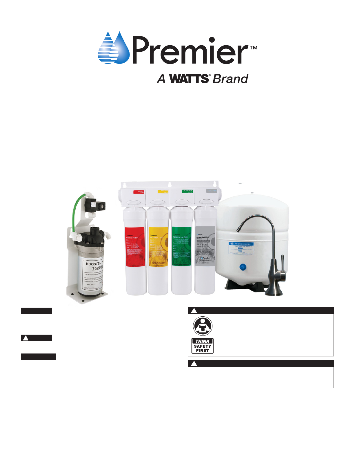
ZeroWaste® Reverse Osmosis Unit
Model: Zero Pure Plus
!
IMPORTANT
If you are unsure about installing your WATTS water filter, contact
a WATTS representative or consult a professional plumber.
!
CAUTION
Discard small parts remaining after the installation.
NOTICE
Failure to install the system correctly voids the warranty.
Handle all components of the system with care. Do not drop,
drag or turn components upside down.
Be sure the floor under the water filter system is clean, level
and strong enough to support the unit.
WARNING
Please read carefully before proceeding with
installation. Your failure to follow any attached
instructions or operating parameters may lead to the
product’s failure.
Keep this Manual for future reference.
!
WARNING
Do not use with water that is microbiologically unsafe or of
unknown quality without adequate disinfection before or
after the system.
Refer to enclosed warranty for operating parameters to ensure proper use with your water supply.
Watts Premier
www.premierh2o.com
P/N WP199520
8716 W Ludlow Drive Suite #1
Peoria, AZ 85381
Canada: Tel. (905) 332-4090
Manual Edition: 09/20/2016
USA: Tel. (800) 752-5582
Page 2

Table of Contents
BEFORE INSTALLATION
Overview ...............................................................................................................................................................................................................1
Using Quick-Connect Fittings .................................................................................................................................................................................2
System Maintenance .............................................................................................................................................................................................2
Installation Notes ...................................................................................................................................................................................................2
Operational Parameters .........................................................................................................................................................................................3
Contents of the Reverse Osmosis (RO) System ......................................................................................................................................................3
Tools Recommended For Installation .....................................................................................................................................................................3
INSTALLATION
System Diagram ....................................................................................................................................................................................................4
Drill a Hole for the Faucet in a Porcelain Sink ........................................................................................................................................................5
Top Mount Twist Faucet Installation ......................................................................................................................................................................6
Adapt-a-Valve Installation ......................................................................................................................................................................................7
Green Tube Connection (Cold Supply) ....................................................................................................................................................................8
Connections at Pump Assembly .............................................................................................................................................................................8
Blue Tube Connection at Pressure Switch ..............................................................................................................................................................8
Electrical Connections ...........................................................................................................................................................................................8
Red Tube Connection (Return Line) ........................................................................................................................................................................8
Tank Ball Valve Installation ....................................................................................................................................................................................9
Reverse Osmosis Module & Pump Assembly Mounting ..........................................................................................................................................9
Tank Valve Connection ..........................................................................................................................................................................................9
OPERATION
Startup Instructions .............................................................................................................................................................................................10
MAINTENANCE
Changing the Filter Cartridges .............................................................................................................................................................................11
RO Membrane Replacement (2 - 5 Years) ............................................................................................................................................................12
Annual Sanitization .............................................................................................................................................................................................12
Check Air Pressure in the Tank ............................................................................................................................................................................13
Replacing the Faucet Battery ...............................................................................................................................................................................14
Procedure for Extended Non-Use (More than 2 months) ......................................................................................................................................14
TECHNICAL & WARRANTY INFORMATION
Troubleshooting ...................................................................................................................................................................................................15
Performance Data Sheet ......................................................................................................................................................................................17
VOC Performance Data Sheet ..............................................................................................................................................................................18
Arsenic Fact Sheet ...............................................................................................................................................................................................19
Service Record ....................................................................................................................................................................................................20
Limited Warranty .................................................................................................................................................................................................22
Page 3

BEFORE INSTALLATION
BEFORE INSTALLATION
Overview
Thank you for your purchase of a state of the art Premier ZeroWaste® Reverse Osmosis Water Treatment System. Water
quality concerns are becoming more of a focus for the public. You may have heard about contaminants in the drinking
water such as Arsenic, Chromium, Cryptosporidium or Giardia. There may also be some local water issues such as high
levels of Lead and Copper. This Premier water treatment system has been designed and tested to provide you with high
quality drinking water for years to come. The following is a brief overview of the system.
About Reverse Osmosis
Osmosis is the process of water passing through a semi permeable membrane in order to balance the concentration of
contaminants on each side of the membrane. A semi permeable membrane is a barrier that will pass only certain particles like clean drinking water, but not other particles like arsenic and lead.
Reverse osmosis uses a semi permeable membrane; however, by applying pressure across the membrane, it concentrates contaminants (like a strainer) on one side of the membrane, producing crystal clear water on the other. This is
why RO systems produce both clean drinking water and rinse water that is flushed from the system. This reverse osmosis system also utilizes carbon block filtration technology, and can therefore provide a higher quality drinking water than
carbon filtration systems alone
What Makes This Unit ZeroWaste
Normally, reverse osmosis sends more water to the drain than what ends up as drinking water. This flushing is necessary for reverse osmosis to work. This unit features a ZeroWaste
be sent to the drain and redirects it into your hot water connection where it can be re-used.
®
®
component that takes the water that would normally
The Stages of Filtration
Your system is a four stage RO which is based upon separate treatment segments within the one complete water filtration system. These stages are as follows:
Stage 1 – Sediment filter, recommended change 6 months.
The first stage of your RO system is a five micron sediment filter that traps sediment and other particulate matter like
dirt, silt and rust which affect the taste and appearance of your water.
Stage 2 – Carbon filter, recommended change 6 months.
The second stage contains a 5 micron carbon block filter. This helps ensure that chlorine and other materials that
cause bad taste and odor are greatly reduced.
Stage 3- Membrane, recommended change 2-5 years.
Stage three is the heart of the reverse osmosis system, the 50GPD (Gallons Per Day) RO membrane. This semi permeable membrane will effectively remove Total Dissolved Solids (TDS), Sodium and a wide range of contaminants such
as Chromium, Arsenic, Copper, Lead as well as Cysts, such as Giardia and Cryptosporidium. Because the process of
extracting this high quality drinking water takes time, your RO water treatment system is equipped with a storage tank.
Stage 4- VOC Block filter, recommend change 12 months.
Through the specialty (VOC) like MTBE’s, Atrazine, Benzene, 2,4-D,Lindane and others from your drinking water. It is
estimated that VOC’s are present in one-fifth of the nation’s water supplies. These water contaminants can enter ground
water from a variety of sources including localized use of herbicides and pesticides, gasoline or oil spills, leaking
underground fuel tanks, septic system cleaners, and chemicals used in the dry-cleaning industry. See performance data
sheet for individual contaminants and reduction performance.
Note: Filter & Membrane life may vary based upon local water conditions and/or use patterns.
Page 1
Page 4
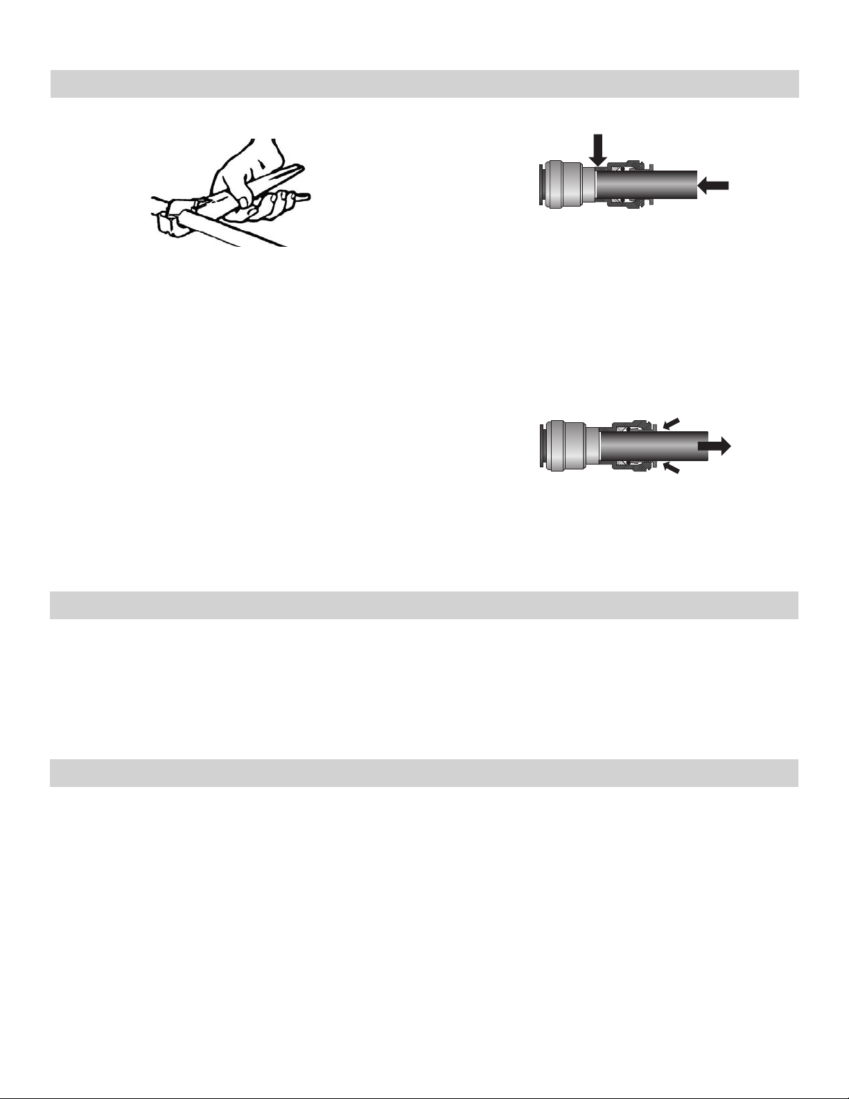
Using Quick-Connect Fittings
Cutting Connecting
Make certain to push the tubing completely into the connector until it comes into contact with the internal tubing
stop. The collet (gripper) has stainless steel teeth which
Cut the tube square. It is essential that the outside diameter be free of score marks and that burrs and sharp edges
be removed before inserting into fitting.
hold the tube firmly in position while the O-ring provides a
permanent leak proof seal.
Pull on the tube to check that it is secure. It is good practice to test the system prior to leaving the site and/or
before use.
Disconnecting
BEFORE INSTALLATION
To disconnect, ensure the system is depressurized before
removing the tube. Push in collet squarely against the face
of the fitting. With the collet held in this position, the tube
can be removed. The fitting can then be reused.
System Maintenance
Just because you cannot taste it, does not mean that it is not there. Contaminants such as Lead, Chromium and Arsenic
are undetectable to the taste. Additionally, over time if you do not replace the filter elements, other bad tastes and
odors will be apparent in your drinking water.
It is important to change out your filters at the recommended intervals as indicated in this system manual. When
replacing the filter elements, pay special attention to any cleaning instructions. Should you have any further questions
please refer to our web site at www.premierH2o.com or call our customer service department at 1-800-752-5582.
Installation Notes
• Not recommended for use on homes equipped with tankless water heaters. Contact Watts Premier for specific
details regarding this unit and tankless water heaters.
• System was tested in a laboratory setting utilizing a hot water heater of 40 gallons set at 120º F. Performance may
vary if your heater is smaller than 40 gallons or set above 120º F, contact the manufacturer for additional details.
• System should not be used on homes equipped with a backflow prevention device on the hot water heater.
• RO unit must be installed a minimum of 25 Pipe feet from water heater
• A non-switched outlet is needed to provide power to the pump.
Page 2
Page 5
Operational Parameters
NOTICE
Installation must comply with state and local plumbing regulations.
BEFORE INSTALLATION
NOTICE
* Hardness: Recommended hardness not to exceed 10 grains per gallon, or 170 parts per million. System will operate
with hardness over 10 grains but the membrane life may be shortened. Addition of a water softener may lengthen the
membrane life.
Water Pressure: The operating water pressure in your home should be tested over a 24 hour period to attain the maximum pressure. If the incoming water pressure is above 100 psi then a water pressure regulator is required. A booster
pump is needed for incoming water pressure under 40psi.
Copper Tube: Reverse Osmosis water should not be run through copper tube as the purity of the water will leach copper causing an undesired taste in water and pin holes may form in the tube.
Do not use with water that is microbiologically unsafe or of unknown quality, without adequate
disinfection before or after the system.
Maximum Minimum
Operating Temperature: 100°F (37.8°C) 40° F (4.4°C)
Operating Pressure: 100 psi (5.98 g/cm²) 40 psi (1.40 kg/cm²)
pH Parameters: 10 5
Iron 0.2 ppm
TDS (Total Dissolved Solids) < 1800 ppm
Turbidity < 5 NTU
Hardness Maximum 10 Grains Per
Gallon (gpg)*
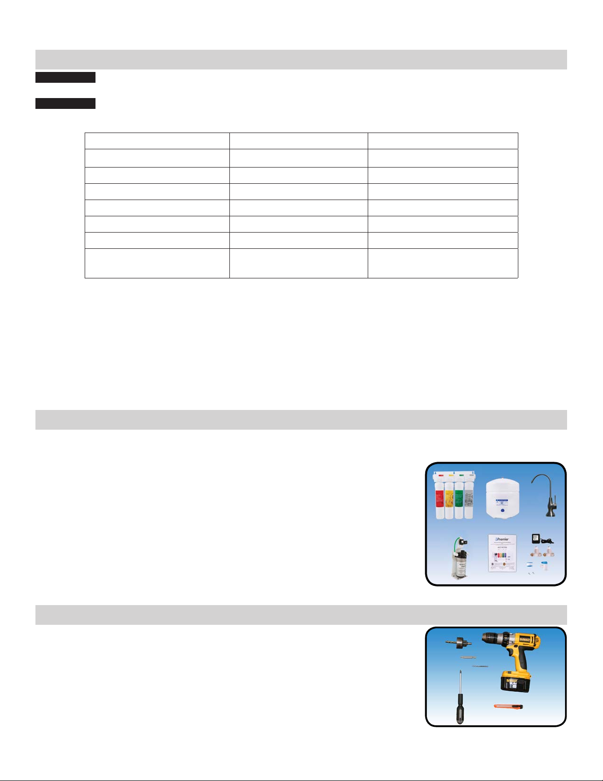
Contents of the Reverse Osmosis (RO) System
Please make sure all of the items listed below are contained in the box. If any of the items are missing please
contact Watts Premier at 800-752-5582 prior to installing.
Tank - White
RO Module (complete with filters)
Pump Assembly
Transformer (Power Plug)
Parts Bag
Faucet
Manual
Tools Recommended For Installation
Small knife
Variable speed drill with Phillips bit
1/8” (3mm) drill bit
Phillips screwdriver
1 1/4” Diamond Tipped Hole Saw bit for faucet opening
Page 3
Page 6
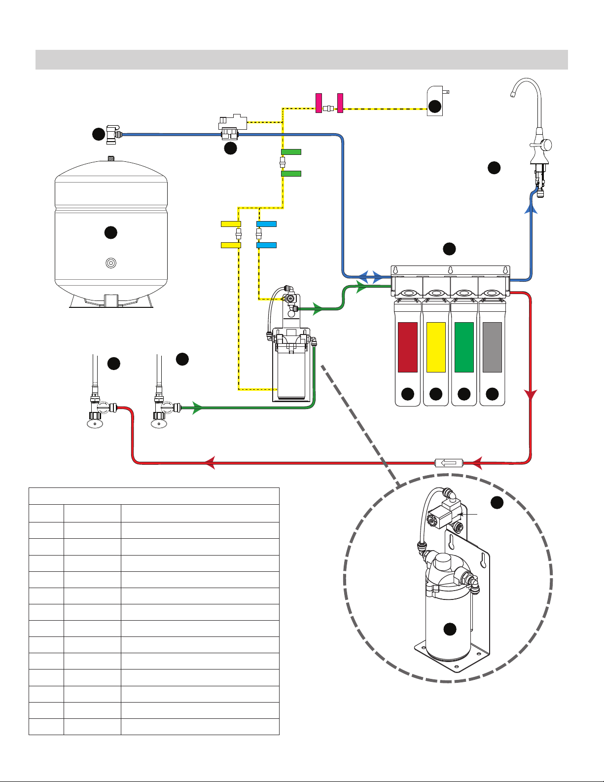
System Diagram
INSTALLATION
INSTALLATION
K
H
TANK
ADAPT
VALVE
BLUE - 1/4” TUBE
F
I
-A-
TANK
I
ADAPT
-A-
VALVE
M
PRESSURE
SWITCH
GREEN- 1/4” TUBE
FEED
TRANSFORMER
FILTER LID
B C
A
D E
G
FAUCET
FAUCET
BLUE - 1/4” TUBE
BRINE - RETURN
RED - 1/4” TUBE
HOT WATER
ANGLE-STOP
(RETURN)
COLD WATER
ANGLE-STOP
(SUPPLY)
RED- 1/4” TUBE
BRINE - RETURN
Parts List
Item Part# Description
A 115304 FILTER LID
B 105311 SEDIMENT FILTER
C 105351 CARBON PRE-FILTER
D 105331 REVERSE OSMOSIS MEMBRANE
E 105381 POST-CARBON VOC FILTER
F 119007 3 GALLON METAL TANK
G 116187 BRUSHED NICKEL TMT FAUCET
H 134018 TANK VALVE
I 560080 ADAPT-A-VALVE
J 152012 BOOSTER PUMP
K 152018 TRANSFORMER
L 152035 SOLENOID (W/O ELBOWS)
M 152032 PRESSURE SWITCH
DOUBLE-CHECK VALVE
L
SOLENOID
PUMP
J
Page 4
Page 7
Drill a Hole for the Faucet in a Porcelain Sink
INSTALLATION
NOTICE
For Marble Counter-tops, we recommend contacting a qualified contractor for drilling a hole in a
marble counter-top.
Note: Most sinks are predrilled with 1½” or 1¼” diameter hole that you can use for your Drinking Water faucet.
(If you are already using it for a sprayer or soap dispenser, see Step 1).
NOTICE
Porcelain sinks are extremely hard and can crack or chip easily. Use extreme caution when
drilling. Watts accepts no responsibility for damage resulting from the installation of faucet.
Diamond tip bit recommended.
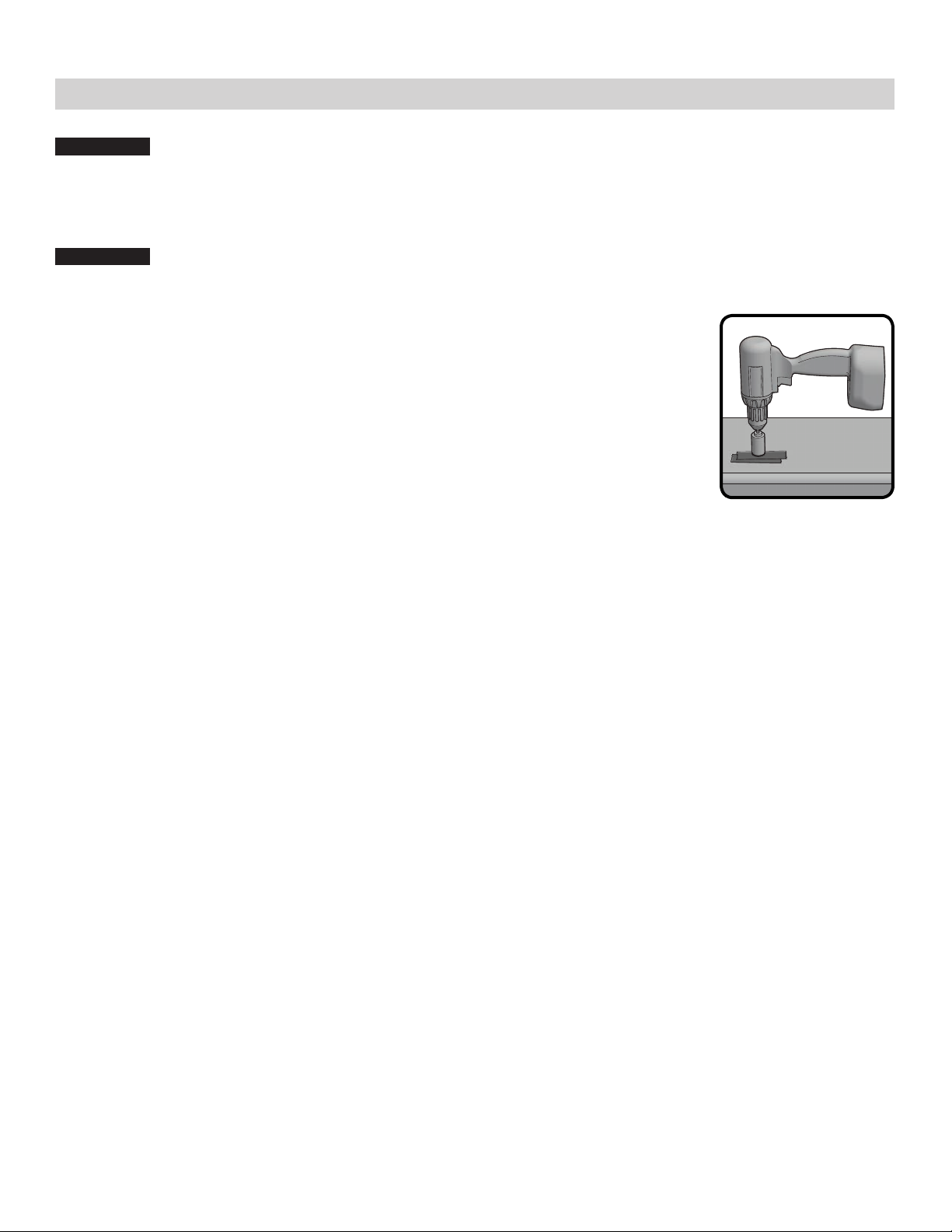
Step 1: Determine desired location for the RO faucet on your sink and place a
piece of masking tape over where the hole is to be drilled. Mark the center
of the hole on the tape.
Step 2 : Using a variable speed drill set on the slowest speed, drill a 1/8“ pilot hole
through both porcelain and metal casing of sink at the marked center of
the desired location. Use lubricating oil or liquid soap to keep the drill bit
cool (If drill bit gets hot it may cause the porcelain to crack or chip).
Step 3: Using a 1.25” diamond tip hole saw, proceed to drill the large hole. Keep
drill speed on the slowest speed and use lubricating oil or liquid soap to
keep the hole saw cool during cutting.
Step 4: After drilling, remove all sharp edges and make sure the surroundings of the sink are cooled before
mounting the faucet.
Page 5
Page 8
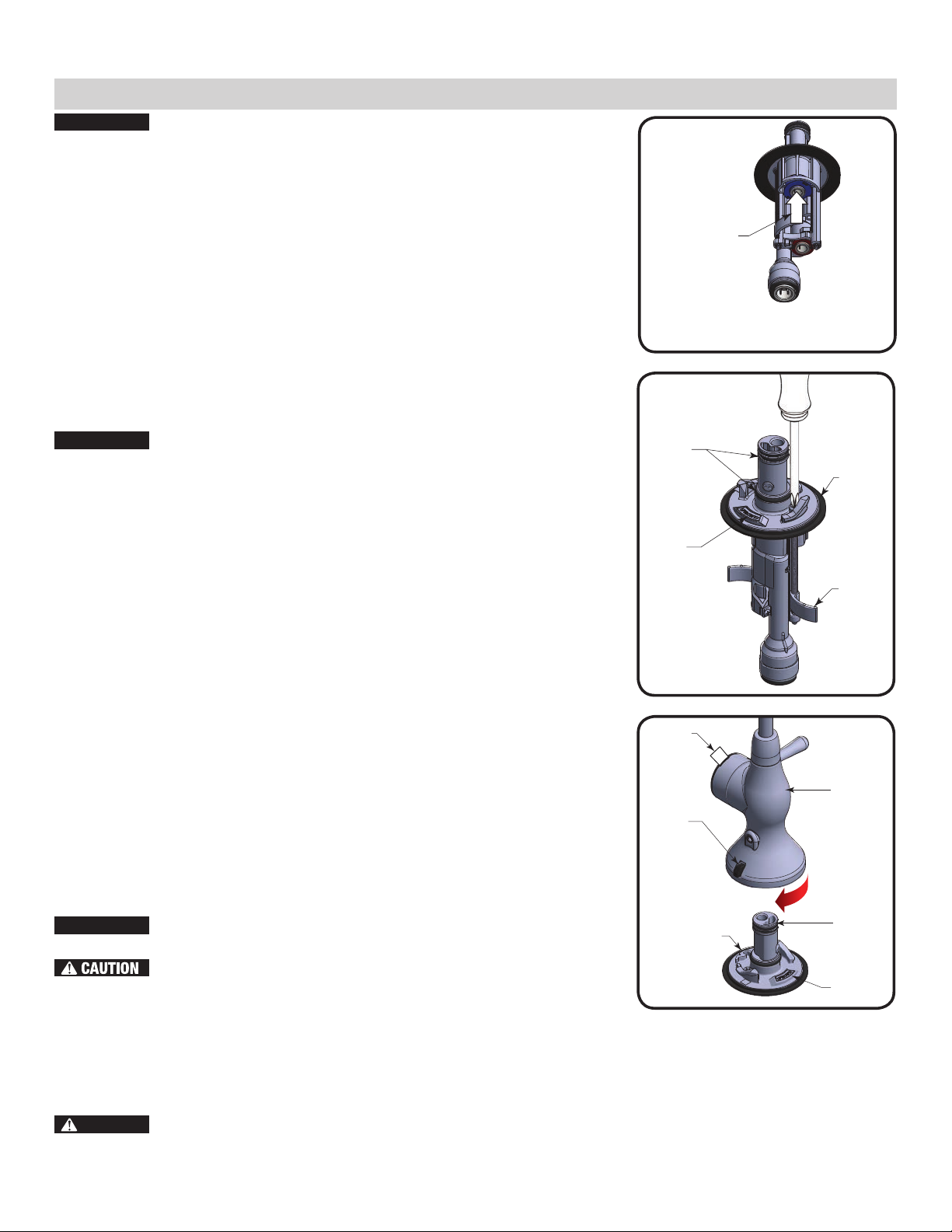
Top Mount Twist Faucet Installation
INSERT
INTO BLUE
PORT ONLY
FRONT
LOWER
FAUCET
ASSEMBLY
UPPER
FAUCET
ASSEMBLY
BACK
TWIST UPPER
ASSEMBLY 45°
ONTO BASE
FAUCET
RELEASE
BUTTON
BATTERY
TAB
O-RINGS
FRONT
RUBBER
WASHER
LOCKING
TABS
NOTICE
This RO Faucet is equipped with quick-connect fittings for easy tube installation. Refer to the guide on Page 2 for more information on how to use
these type of fittings.
Connect the Tubing
Step 5 Locate the 1/4” tube that is already connected to the filter lid,
Mount the faucet
NOTICE
Step 6 Make sure the Locking Tabs are “tucked”. Feed the tubes and
The faucet being used is an air-gap faucet, but is being used
for this non air-gap installation. The red and black color
coded ports on the faucet will remain unused. ONLY the blue
port will be used.
labeled “Faucet”) and connect to the 1/4” blue quick-connect
fitting at the bottom of the faucet. Make sure the tube is inserted
the full 3/4” into the fitting.
A 1.25” mounting hole is required for faucet installation
the lower faucet assembly through the mounting hole in the sink.
Test fit faucet placement.
INSTALLATION
Figure A
Step 7 Make sure the lower faucet assembly is seated properly inside of
the rubber washer groove
NOTE: Arrow on base indicates FRONT of faucet.
Step 8 Using a Phillips screwdriver, tighten the two screws until snug.
Then, tighten each screw alternately until faucet is secure. Do
not overtighten!
Figure B
Step 9 Inspect O-rings on lower faucet assembly. Lubricate with water-
soluble lubricant if needed.
Assemble the faucet
Step 10 Align the release button on the back of the upper faucet assembly
approximately 45° left off the back of the lower faucet assembly.
Step 11 Press the upper faucet assembly firmly on-to the lower faucet
assembly and twist clockwise until locked into place. Remove
battery cover on faucet handle, pull battery tab and replace
battery cover.
NOTICE
NOTE: This faucet is equipped with a filter change indicator. The indicator light will flash BLUE while the water is being
dispensed. After approximately six months or 2000 gallons of filtered water used the light will change to RED, indicating that filters should be changed. After filter change you must reset the monitor (Follow the Faucet Indicator Battery
Replacement procedure on page 13).
DANGER
To Remove Upper Assembly press in the release button and
twist upper faucet assembly counter- clockwise.
Do not remove upper faucet assembly until all water has
been drained from the system and system has been fully
depressurized.
This product contains a button cell battery. If swallowed, it could cause severe injury or death in
just 2 hours. Seek medical attention immediately.
Page 6
Figure C
Page 9

D
B
Line from
Angle Stop
Valve
Faucet
Connection
Faucet Line
Angle Stop
Valve
C
B
A
Adapt-a-Valve Installation
INSTALLATION
NOTICE
Do not use Teflon tape with the Adapt-A-Valve™.
Parts List for Adapt-A-Valve
Item Description
Faucet
Connection
B
Line from
Angle Stop
Valve
A Brass Adapter with black washer
B Plastic Adapt-A-Valve & black collet
C White Rubber Washer
D Brass Adapter with no washer
For 3/8” Configuration
Step 12: Turn off the hot and cold water valves to the faucet by turning the angle stop valve completely off.
For 1/2” Configuration
Step 13: Open sink faucet to relieve pressure from both the hot and cold water side.
Step 14: Choosing the configuration that fits your plumbing, attach the Adapt-A-Valve™ as illustrated in the
diagrams above for both the hot and cold valves.
NOTICE
Make sure that the black collet is installed in to the 1/4” opening on the Adapt-a-valve. Don’t
forget to install the white compression washer with the 3/8” configuration. The Brass Adapters
do not need to be tightened with a wrench, only finger tight.
Page 7
Page 10

INSTALLATION
STEP 16 - GREEN TUBE
ADAPT-A-VALVE
TO PUMP
STEP 17 - GREEN TUBE
FILTER LID
TO SOLENOID
Green Tube Connection (Cold Supply)
Step 15: Location the 1/4” Green tube in the parts bag. Insert one end of the green tube into the plastic adapt-a-
valve that is attached to the cold water supply.
Connections at Pump Assembly
NOTICE
Green Tube - Adapt-A-Valve to Pump
Step 16: Insert the open end of the 1/4” green tube from the
Green Tube - Filter Lid to Solenoid
Step 17: Insert the 1/4” green tube from the RO Module
Make sure all tubes are pushed in all the way to the
tube stop
Cold Water Adapt-a-valve into the quick-connect fitting
on the inlet (right) side of the booster pump. (see
diagram)
(Labeled “Cold”) into the Open quick-connect fitting on
the solenoid (see diagram)
Blue Tube Connection at Pressure Switch
Blue Tube - Filter Lid to Pressure Switch
Step 18: Insert the 1/4” blue tube from the RO System (Labeled “Tank”) into the quick-connect fitting on the
pressure switch
Blue Tube - Tank to Pressure Switch
Step 19: In the parts bag, locate the 1/4” blue tube and Insert one end into the quick-connect fitting on the
pressure switch.
NOTICE
The pressure switch can be installed in either direction.
Electrical Connections
Step 20: Locate the wire harness in the parts bag and connect the wires between the transformer to pressure
NOTICE
Red Tube Connection (Return Line)
Step 21: Locate the 1/4” red tube that is already connected to the back of the filter lid and connect the open end
switch, pressure switch to wire harness and wire harness to pump and solenoid. You will connect the
wires so the color of the stickers on the wires match up.
Do not plug in the transformer (plug) into the outlet yet.
into the HOT water return adapt-a-valve. Make sure the tube is pushed in all the way to the tube stop.
Page 8
Page 11

Tank Ball Valve Installation
Step 22: Teflon tape must be applied in a clockwise direction. Wrap (7 to 12
turns) around the male pipe threads (MPT) on the stainless steel fitting
on top of the tank.
Step 23: Thread the quick connect ball valve (supplied in the parts bag) onto
the stainless steel connector on the tank.
Note: Do not over-tighten plastic connections.
Reverse Osmosis Module & Pump Assembly Mounting
INSTALLATION
Step 24 : The parts bag has 4 self-tapping screws. The first two are for mount-
ing the RO Module and the last two are for mounting the pump
assembly. Using an electric drill with a phillips bit, screw the first
two screws into the cabinet wall approximately 7-7/8” apart and 16”
from the bottom of the cabinet. This will be for the RO Module. The
pump assembly can either be hung on the cabinet wall or it can be
left standing on the cabinet floor. If you hang the pump bracket, place
another two screws into the cabinet wall approximately 3” apart and
10” from the bottom of the cabinet. Make sure that the hoses will reach between the pump and RO
Module
Tank Valve Connection
Step 25: Position tank in desired location. Stand it upright or lay it on its
side (using the black plastic stand). Measure the blue tube (marked
“TANK”) from the pump assembly to the tank and cut it to length
leaving a straight, square edge. Insert the tube into the quick connect
fitting on the tank ball valve. Make sure the tube is pushed in all the
way to the tube stop (see page 2 for quick connect fitting use directions).
Page 9
Page 12

Startup Instructions
ON
OFF
!
WARNING
To prevent the possibility of electrical shock, clean up any water on cabinet floor and dry all
water from outside of RO unit.
OPERATION
OPERATION
Congratulations!
You have completed the installation of your new Reverse Osmosis system. Please
Follow the Startup Instructions.
Step 1: Turn on the incoming hot and cold water angle stop valves.
Step 2: Turn both of the adapt-a-valves on and check the system for leaks
and tighten fittings as necessary.
NOTICE
If you have connected your RO system to a refrigerator / ice
maker, make sure the ice maker is off (do not allow water to
flow to the ice maker) until flushing (Step 9) is complete and
the tank has been allowed to fill completely. Connection from
the RO to the ice maker system should have an in-line valve
installed before the ice maker so it can easily be closed to prevent water flowing to the ice maker during start up and periodic maintenance. Your storage tank must be allowed to fill up
fully in order for the ice maker system to work properly.
Step 3: Plug the transformer into the electrical outlet under the sink.
Step 4: Make sure the ball valve on the tank is open
Step 5: Open the RO faucet and leave it open until water begins to drip. Then close the faucet. The tank will
take between 2 - 4 hours to fill.
NOTICE
If the pump doesn’t start, make sure there is power at the electrical outlet and that it is not con-
trolled by the garbage disposal switch.
Step 6: After the tank has filled once, open the RO faucet and drain the tank.
NOTICE
Water may be cloudy or milky due to air in the system and carbon particles flushing out of the
final polishing filter. This condition will resolve itself after flushing a couple of tanks of water.
Step 7: Complete step #6 two more times. The process of flushing the system first three times should take
about one day to complete. The fourth tank can be used for drinking water.
NOTICE
NOTICE
Check daily over the next week to ensure no leaks are present.
Flushing of the tank 3 times is only necessary during the initial startup and after replacing the
membrane.
Page 10
Page 13

MAINTENANCE
MAINTENANCE
Changing the Filter Cartridges
Your RO module is equipped with valve heads which will automatically turn off the water supply to each filter when the
filter is released, thus you do not need to turn off the incoming water supply at the Adapt-a-Valve. The RO faucet must
be off when filters are replaced. To make the removal of the filter cartridges easier, the heads & cartridges may be
swiveled up to 90 degrees as shown in the pictures below.
6 Month System Maintenance
Replace: Sediment Filter (Red Label PN# 105311)
Carbon Pre-Filter (Yellow Label PN# 105351)
Annual Maintenance
Replace: Sediment Filter (Red Label PN# 105311)
Carbon Pre-Filter (Yellow Label PN# 105351)
VOC Carbon Post-Filter (Silver Label PN# 105381)
Tip: This is a good time to check the air pressure in your storage tank. For instructions please see page 12.
Step 1: Unplug the transformer from the electrical outlet
Step 2: Place a towel under the filters to catch any excess water that may drip
PRESS
out from the filters during the changeover.
Step 3: To remove a filter cartridge: Push & hold the button on the valve head
above the filter. Pull cartridge downward (from the head) to remove.
Release button and discard old filter.
Step 4: To install a filter cartridge: Remove the seal cap and insert the cartridge
into the valve head until you hear an audible “click” (the button does
PULL
not need to be pressed to install new filters).
Step 5: If performing the annual maintenance, flush the first tank full after
completing the annual maintenance.
TIP: If the new filter cartridge won’t snap in easily or pops off, relieve
pressure to the system by turning off the water supply using the
adapt-a-valve and then install the cartridge. Once the cartridge is
seated, turn the water supply back on to your RO unit.
!
WARNING
To prevent the possibility of electrical shock, clean up any water on cabinet floor and dry all
water from outside of the RO unit before plugging in the transformer.
Step 6: Plug the transformer back into the electrical outlet.
This reverse osmosis system contains a replaceable component (the RO membrane) which is critical to the efficiency of the system. Replacement of this reverse osmosis membrane should be with one of identical specifications as defined by Premier to assure the same efficiency and contaminant reduction performance.
Page 11
Page 14

MAINTENANCE
POINT HOSE
ENDS AWAY
FROM FACE
DOSING SYRINGE
WITH NO NEEDLE
RO Membrane Replacement (2 - 5 Years)
Replace: RO Membrane - 50 GPD (Green Label PN# 105331)
Membranes have a life expectancy between 2 and 5 years, depending on the incoming water conditions and the amount
the RO system is used. This reverse osmosis membrane is critical for effective reduction of total dissolved solids (TDS).
The product water should be tested periodically to verify that the system is performing satisfactorily.
Normally, a membrane would be replaced during a semiannual or annual filter change. However, if at any time you
notice a reduction in water production or an unpleasant taste in the reverse osmosis water, it could be time to replace
the membrane. Premier recommends replacing the membrane when TDS reduction falls below 75%.
A water sample may be sent to Premier for a free diagnosis of your membranes performance. To send a water sample,
use 2 clean containers and fill 1/2 cup of tap water in one container and 1/2 cup of RO water in 2nd container. Clearly
label each sample. Send the samples to the address listed on the cover of this manual attention “Water Samples”.
Premier will test the water and mail or call you with the results.
Annual Sanitization
NOTICE
Do not change your post-carbon filter until the sanitization has
been completed. The pre-filters and membrane can be changed
before the sanitization
Step 1: Turn off the water supply to your RO system at the adapt-a-valve and
open the RO faucet to drain the storage tank.
NOTICE
If you have connected your RO system to a refrigerator/ice
maker, make sure the connection has been turned off. Do not reopen the connection until the sanitization process is complete.
Step 2: Locate the tube that runs between your filter module and the storage
tank and disconnect at both ends.
Step 3: Drain any remaining water in the tube
Step 4: Hold both ends of the tube together with the ends pointed away from
your face. Using a dosing syringe (see figure) slowly insert 1 teaspoon
(5 mL) of common household bleach into the tube.
!
WARNING
!
DANGER
Do not use needle syringe
IF BLEACH GETS IN EYES: Hold eye open and rinse slowly and
gently with water for 15 - 20 minutes. Remove contact lenses if
present, after the first 5 minutes, then continue rinsing eye. Call
a poison control center or doctor for treatment advice.
Step 5: While covering one end of the tube with your finger, insert the other
into the tank. Then insert the open end into the filter module.
Step 6: Turn the incoming water back on and let the system fill for
approximately 10 minutes
Step 7: Turn off the incoming water and let the system sit for 1 minute.
Page 12
Page 15

MAINTENANCE
TO REMOVE
SCHRADER VALVE
Step 8: Drain the system completely and then follow the startup procedure - filling then draining two full tanks
of water.
Step 9: Replace the post-carbon filter once complete.
Check Air Pressure in the Tank
NOTICE
Check air pressure in the storage tank when you notice a decrease in available water
from the RO system. Air can be added with a bicycle pump using the schrader valve
that is located on the lower side of the tank behind the blue plastic cap.
Step 1: Turn off the incoming water supply to the RO.
Step 2: Open the RO Faucet and allow water to drain from the tank until it is
TIP: When water from the RO faucet slows to a trickle, with the faucet
Step 3: Once all water in the tank is purged, check air pressure using an air pressure gauge, it should read
Check air pressure only when tank is empty of water!
completely empty.
still in the open position, you may add air to the tank to purge
any left over water, this will ensure that the tank is completely
empty.
between 5 - 7 PSI. (Digital air pressure gauge is recommended)
Step 4: Follow startup procedure on page 10.
Page 13
Page 16

MAINTENANCE
COVER
CR2032 BATTERY
(PN# 116080)
ALIGNMENT TAB
ALIGNMENT NOTCH
Replacing the Faucet Battery
Step 1: Turn the handle on the storage tank ball valve to the “off” position
and lower faucet handle to “on” position.
Step 2. Remove the faucet handle cover at the slot - (A). Note: Water will
dribble out of the spout, use caution when handling the electronic
components.
Step 3. Slide the old battery out and replace with new battery. Once the
battery is pushed into the clip a red and blue light will flash indicating proper installation.
Step 4. Replace cover assembly onto the faucet handle while aligning the
tab on the cover with the notch on the faucets handle.
Procedure for Extended Non-Use (More than 2 months)
Step 1: Unplug transformer from electrical outlet
Step 2: Turn off the hot and cold water valves to your RO system and open the RO faucet to drain the storage
tank.
Step 3: Once the storage tank is empty, remove all filter cartridges (order not important),
Step 4: Place filters into a sealed plastic bag and store in your refrigerator.
To Restart System:
Step 1: Reinstall all filters on to the RO unit. Filters are color coded to match the filter heads they snap in to.
Refer to page 11 step three for cartridge installation procedure. If you choose to Sanitize your system
now, refer to page 12.
Step 2: Turn on the incoming hot and cold water angle stop valves.
Step 2: Turn both of the adapt-a-valves on and check the system for leaks and tighten fittings as necessary.
NOTICE
Step 4: Plug in the transformer into the electrical outlet
NOTICE
Step 3: Open the RO faucet and leave it open until water begins to trickle out (it will come out slowly).
Check daily over the next week to ensure no leaks are present.
NOTE: If you have connected your RO system to a refrigerator / ice maker, make sure the ice
maker is off (do not allow water to flow to the ice maker) until the tank has been allowed to
completely fill.
Step 4: Close the RO faucet allowing the storage tank to fill with water. It may take 2 to 4 hours to fill the tank
completely depending on the production capability of the membrane, local water temperature and water
pressure.
Step 5: After the Tank has filled, open the RO Faucet to flush the tank completely. You will know that the tank
is empty when the flow rate from the RO faucet is down to a trickle. The second tank can be used for
drinking.
Page 14
Page 17

TECHNICAL & WARRANTY INFORMATION
Troubleshooting
TECHNICAL & WARRANTY INFORMATION
NOTICE
Problem Possible Causes Solution
1. Low/Slow Production Low Water pressure Incoming water pressure to unit must be at
2. Milky colored water Air in system Air in the system is a normal occurance with
3. System is constantly running or
pump won’t turn off
Before disconnecting any tubes, make sure to unplug the power then turn off the water valves
and depressurize the system
least 40 psi.
Old adapt-a-valve If you have recently installed the system,
make sure any old adapt-a-valves, from previous systems, have been replaced
Crimps in tubing Check tubing and straighten or replace as
necessary
Clogged pre-filters Replace pre-filters
Fouled Membrane Replace Membrane. Make sure hot water
return has been turned on
Clogged Post-Carbon Filter Replace Post-Carbon filter
the initial start-up after RO installation or
filter replacement. This will disappear during
normal use within 1-2 weeks. If it continues,
check incoming water.
Crimps in tubing Check tubing and straighten or replace as
necessary
Clogged pre-filters Replace prefilters
Fouled Membrane Replace Membrane. Make sure hot water
return has been turned on
Other Turn off the valve at the top of the tank and
check water production from faucet. The sys-
tem should produce at least 3-4 ounces (89-
118 mL) per minute with the tank off. If it is
producing less, check for clogged pre-filters
or a fouled membrane.
4. Pump won’t turn on No power at outlet Make sure the outlet is not controlled by the
garbage disposal switch. Switch to a different outlet.
Electronic Connections are
loose
Transformer is burned out Make sure filters aren’t clogged which can
Make sure connections at controller and wire
harness are secure.
cause the pump to draw extra amperage and
burn out the transformer. Replace transformer.
Page 15
Page 18

TECHNICAL & WARRANTY INFORMATION
5. Noise from pump Pump is vibrating against adja-
cent object
Make sure the pump is attached to the
bracket and standing on the rubber feet at the
bottom of the bracket. If pump is hanging on
wall, add padding (such as foam) between
bracket and wall to dampen vibration.
Pump is damaged Replace pump
6. Small amount of water in storage
tank
System is starting up Normally it takes 4-6 hours to fill tank. Note:
low storage tank incoming water pressure
and/or temperature can drastically reduce
production rate.
Low water pressure See Item 1
Air pressure in tank is too high Repressurize Tank - See Page 12
Low air pressure in tank Repressurize Tank - See Page 12
7. Low flow from faucet. Low air pressure in tank Repressurize Tank - See Page 12
8. Hot water from RO system System is too close to the hot
water heater
Make sure the system is at least 25 feet away
from the hot water heater.
9. Leak at Fitting Damaged Tubing Disconnect the tube (See Section “Using
Quick-Connect Fittings” at beginning of
manual) then cut about 1” from the tube or
replace tube and then re-insert. Replace tubing if necessary.
Damaged Fitting Replace fitting
10. Unpleasant taste from water Tank needs to be sanitized Sanitize your system
Filters are Fouled Replace Filters
Filters weren’t removed prior to
Replace filters and Sanitize your system
an extended period of non-use
11. Leaking at faucet Faulty o-rings on lower faucet
assembly
12. TDS Levels are high Bad membrane or connection
to hot water outlet is off
Check o-rings. Lubricate o-rings or replace
lower faucet assembly if damaged.
The system flushes out the waste/brine water
to the hot water connection under the sink. If
this connection is turned off, that can foul an
RO Membrane and clog or cause higher TDS
levels.
Page 16
Page 19

TECHNICAL & WARRANTY INFORMATION
Performance Data Sheet
Watts Premier
8716 W Ludlow Drive Suite #1
Peoria, AZ 8538
Model: Zero Pure Plus
GENERAL USE CONDITIONS:
1. Do not use with water that is microbiologically unsafe or of unknown quality without adequate disinfection before or after the system.
Systems certied for cyst reduction may be used on disinfected waters that may contain lterable cysts.
2. Operating Temperature: Maximum 100° F (38° C) Minimum 40° F (4.4° C)
3. Operating Water Pressure: Maximum 85 psi (5.98 kg/cm²) Minimum 20 psi (1.41 kg/cm²)
3. Maximum ow Rate: 0.50 gpm (1.89 lpm)
RECOMMENDED REPLACEMENT PARTS AND CHANGE INTERVAL:
Note: Depending on incoming feed water conditions replacement time frame may vary.
Description Part Number Change Time Frame
Stage 1: Sediment 105311 6 Months
Stage 2: Pre-Carbon 105351 6 Months
Stage 3: RO Membrane 105331 2 to 5 years
Stage 4: VOC Post-Carbon 105381 12 Months
This membrane has been tested by an independent laboratory for the reduction of the substances listed below. The concentration of the indicated substances in water entering the system was reduced to a concentration less than or equal to the permissible limit for water leaving the system. Testing
performed under standard laboratory conditions, actual performance may vary.
SUBSTANCE
Arsenic (Pentavalent) 0.310 0.001 99.6% 7.24 50 psi 0.002 0.30 ± 10% 0.010
Barium Reduction 9.2 0.08 99.0 7.64 50 psi 0.12 10.0 ± 10% 2.0
Cadmium Reduction 0.031 0.0004 98.0 7.49 50 psi 0.0008 0.03 ± 10% 0.005
Chromium (Hexavalent) 0.030 0.002 99.0 7.24 50 psi 0.004 0.03 ± 10% 0.1
Chromium (Trivalent) 0.030 0.001 99.0 7.64 50 psi 0.002 0.03 ± 10% 1.3
Copper Reduction 3.2 0.02 99.0 7.40 50 psi 0.04 3.0 ± 10% 1.3
Cysts 92,000#/mL 3#/mL 99.99 7.44 50 psi 18 minimum 50,000#/mL N/A
Fluoride Reduction 8.7 0.19 97.0 7.24 50 psi 0.3 8.0 ± 10% 1.5
Lead Reduction 0.15 0.002 98.8 7.39 50 psi 0.3 0.15 ± 10% 0.0107
Radium 226/228 25 pCi/L 5 pCi/L 80 7.24 50 psi 0.005 25pCi/L ± 10% 5 pCi/L
Selenium 94.85 <0.2 97.0 7.24 50 psi 5 pCi/L 0.10 ± 10% 0.05
TDS 770 35 95.0 7.28 50 psi 26.0 750 ± 40mg/L 187
Turbidity 11.3 0.1 99.0
Avg In.
(mg/L)
Avg. Eff.
(mg/L)
% Reduction pH Pressure
7.43 50 psi 0-1 11 ± 1mg/L 0.5 NTU
Max. Eff.
(mg/L)
Inf. Challenge
concentration
(mg/L)
Max. Allowable
concentration
(mg/L)
Depending on water chemistry, water temperature, and water pressure Premier’s R.O. Systems production and performance will vary.
REFER TO OWNER’S INSTALLATION/SERVICE MANUAL FOR FURTHER MAINTENANCE REQUIREMENTS AND WARRANTY INFORMATION.
Page 17
Page 20

VOC Performance Data Sheet
TECHNICAL & WARRANTY INFORMATION
SUBSTANCE PERCENT REDUCTION
ALACHLOR >98% 0.05 0.001
ATRAZINE >97% 0.1 0.003
BENZENE >99% 0.081 0.001
BROMODICHLOROMETHANE (TTHM) >99.8% 0.300 +/- 0.30 0.015
BROMOFORM (TTHM) >99.8% 0.300 +/- 0.30 0.015
CARBOFURAN (Furadan) >99% 0.19 0.001
CARBON TETRACHLORIDE 98% 0.078 0.002
CHLOROBENZENE (Monochlorobenzene) >99% 0.077 0.001
CHLOROPICRIN 99% 0.015 0.000
CHLOROFORM (TTHM) >99.8% 0.300 +/- 0.30 0.015
2, 4-D 98% 0.11 0.002
DBCP (see Dibromochloropropane) >99% 0.052 0.000
1,2-DCA (see 1,2-DICHLOROETHANE) 95% 0.088 0.005
1,1-DCE (see 1,1-DICHLOROETHYLENE) >99% 0.083 0.001
DIBROMOCHLOROMETHANE (TTHM;
Chlorodibromomethane) >99.8% 0.300 +/- 0.30 0.015
DIBROMOCHLOROPROPANE (DBCP) >99% 0.052 0.000
o-DICHLOROBENZENE (1,2 Dichlorobenzene) >99% 0.08 0.001
p-DICHLOROBENZENE (para-Dichlorobenzene) >98% 0.04 0.001
1,2-DICHLOROETHANE (1,2-DCA) 95% 0.088 0.005
1,1-DICHLOROETHYLENE (1,1-DCE) >99% 0.083 0.001
CIS-1,2-DICHLOROETHYLENE >99% 0.17 0.001
TRANS-1,2- DICHLOROETHYLENE >99% 0.086 0.001
1,2-DICHLOROPROPANE (Propylene Dichloride) >99% 0.08 0.001
CIS-1,3- DICHLOROPROPYLENE >99% 0.079 0.001
DINOSEB 99% 0.17 0.000
EDB (see ETHYLENE DIBROMIDE) >99% 0.044 0.000
ENDRIN 99% 0.053 0.001
ETHYLBENZENE >99% 0.088 0.001
ETHYLENE DIBROMIDE (EDB) >99% 0.044 0.000
Furadan (see CARBOFURAN) >99% 0.19 0.001
HALOACETONITRILES (HAN)
BROMOCHLOROACETONITRILE 98% 0.022 0.001
DIBROMOACETONITRILE
DICHLOROACETONITRILE 98% 0.010 0.000
TRICHLOROACETONITRILE 98% 0.015 0.000
HALOKETONES (HK):
1,1-DICHLORO-2-PROPANONE 99% 0.007 0.000
1,1,1-TRICHLORO-2-PROPANONE 96% 0.008 0.000
HEPTACHLOR >99% 0.25 0.000
HEPTACHLOR EPOXIDE 98% 0.011 0.000
HEXACHLOROBUTADIENE (Perchlorobutadiene) >98% 0.044 0.001
HEXACHLOROCYCLOPENTADIENE >99% 0.06 0.000
LINDANE >99% 0.055 0.000
METHOXYCHLOR >99% 0.05 0.000
Methylbenzene (see TOLUENE) >99% 0.078 0.001
Monochlorobenzene (see CHLOROBENZENE) >99% 0.077 0.001
PCE (see TETRACHLOROETHYLENE) >99% 0.081 0.001
PENTACHLOROPHENOL >99% 0.096 0.001
Perchlorobutadiene (see HEXACHLOROBUTADIENE) >98% 0.044 0.001
Propylene Dichloride (see 1,2 -DICHLOROPROPANE) >99% 0.08 0.001
SIMAZINE >97% 0.12 0.004
Silvex (see 2,4,5-TP) 99% 0.27 0.002
STYRENE (Vinylbenzene) >99% 0.15 0.001
1,1,1-TCA (see 1,1,1 - TRICHLOROETHANE) 95% 0.084 0.005
TCE (see TRICHLOROETHYLENE) >99% 0.18 0.001
1,1,2,2- TETRACHLOROETHANE >99% 0.081 0.001
TETRACHLOROETHYLENE >99% 0.081 0.001
TOLUENE (Methylbenzene) >99% 0.078 0.001
2,4,5-TP (Silvex) 99% 0.27 0.002
TRIBROMOACETIC ACID 0.042 0.001
1,2,4 TRICHLOROBENZENE (Unsymtrichlorobenzene) >99% 0.16 0.001
1,1,1-TRICHLOROETHANE (1,1,1-TCA) 95% 0.084 0.005
1,1,2-TRICHLOROETHANE >99% 0.15 0.001
TRICHLOROETHYLENE (TCE) >99% 0.18 0.001
TRIHALOMETHANES (TTHM) (Chloroform; Bromoform;
Bromodichloromethane; Dibromochloromethane) >99.8% 0.300 +/- 0.30 0.015
Unsym-Trichlorobenzene (see 1,2,4-
TRICHLOROBENZENE)
Vinylbenzene (see STYRENE)
XYLENES (TOTAL) >99% 0.07 0.001
98% 0.024 0.001
>99%
0.16 0.001
>99% 0.15 0.001
INFLUENT CHALLENGE
CONCENTRATION
(MG/L UNLESS NOTED)
MAXIMUM PERMISSIBLE IN
PRODUCT WATER
Page 18
Page 21

TECHNICAL & WARRANTY INFORMATION
Arsenic Fact Sheet
Arsenic (As) is a naturally occurring contaminant found in many ground waters. Arsenic in water has no color, taste or
odor. It must be measured by an arsenic test kit or lab test.
Public water utilities must have their water tested for arsenic. You can obtain the results from your water utility contained within your consumer confidence report. If you have your own well, you will need to have the water evaluated.
The local health department or the state environmental health agency can provide a list of test kits or certified labs.
There are two forms of arsenic: pentavalent arsenic (also called As (V), As (+5)) and trivalent arsenic (also called As (III),
As (+3)). In well water, arsenic may be pentavalent, trivalent, or a combination of both. Although both forms of arsenic
are potentially hazardous to your health, trivalent arsenic is considered more harmful than pentavalent arsenic.
RO systems are very effective at removing pentavalent arsenic. A free chlorine residual will rapidly convert trivalent
arsenic to pentavalent arsenic. Other water treatment chemicals such as ozone and potassium permanganate will also
change trivalent arsenic to pentavalent arsenic. A combined chlorine residual (also called chloramine) where it does convert trivalent arsenic to pentavalent arsenic, may not convert all the trivalent arsenic in to pentavalent arsenic. If you get
your water from a public water utility, contact the utility to find out if free chlorine or combined chlorine is used in the
water system.
This Watts Premier reverse osmosis system is designed to remove up to 98% of pentavalent arsenic. It will not convert
trivalent arsenic to pentavalent arsenic. Under laboratory standard testing conditions, this system reduced 0.30 mg/L
(ppm) pentavalent arsenic to under 0.010 mg/L (ppm) (the USEPA standard for drinking water). Actual performance of
the system may vary depending on specific water quality conditions at the consumer’s installation. In addition to the
independent laboratory standard testing conditions, Watts Premier has conducted additional field testing on our reverse
osmosis units to determine trivalent arsenic reduction capabilities. Based upon Watts Premier field testing, it has been
determined that the RO units are capable of reducing up to 67% of trivalent arsenic from the drinking water.
This reverse osmosis system contains a replaceable component critical to the efficiency of the system. Replacement of
the reverse osmosis component should be with one of identical specifications, as defined by the manufacturer, to ensure
the same efficiency and contaminant reduction performance. Specific component identification and ordering information
can be found in the maintenance section of this manual, by phone at 1-800-752-5582 or online at www.premierH2o.
com
Page 19
Page 22

Service Record
Date of Purchase: _______________ Model Number: ZERO PURE PLUS Serial Number: _______________
Date of Install: _________________ Installed by: __________________
Date Changed: Sediment Pre-Filter
(6 Months)
Carbon Pre-Filter
(6 Months)
Membrane
(2-5 Years)
VOC Post-Filter
(12 Months)
Page 20
Page 23

THIS PAGE INTENTIONALLY LEFT BLANK
Page 24

Limited Warranty
What your Warranty Covers:
If any part of your ZERO PURE PLUS is defective in workmanship (excluding replaceable filters ), return unit after obtaining a return authorization (see
below), within 1 year of the original retail purchase, Watts Premier will repair or, at Watts Premier’s option, replace the system at no charge.
How to obtain Warranty Service:
For warranty service, call 800-752-5582 for a return authorization number. Then, ship your unit to our factory, freight and insurance prepaid, with proof
of date of original purchase. Please include a note stating the problem. Watts Premier will repair it, or replace it, and ship it back to you prepaid.
What this warranty does not cover:
This warranty does not cover defects resulting from improper installation, (contrary to Watts Premier printed instructions), from abuse, misuse, misapplication, improper maintenance, neglect, alteration, accidents, casualties, fire, flood, freezing, environmental factors, water pressure spikes or other such
acts of God.
This warranty will be void if defects occur due to failure to observe the following conditions:
1. The System must be hooked up to a potable municipal or well cold water supply.
2. The pH of the water must not be lower than 5 or higher than 10.
3. The incoming water pressure must be between 20 and 85 pounds per square inch.
4. Incoming water to the system cannot exceed 100 degrees F (38 degrees C.)
This warranty does not cover any equipment that is relocated from the site of its original installation.
This warranty does not cover any charges incurred due to professional installation.
LIMITATIONS AND EXCLUSIONS:
WATTS PREMIER WILL NOT BE RESPONSIBLE FOR ANY IMPLIED WARRANTIES, INCLUDING THOSE OF MERCHANTABILITY AND FITNESS FOR A
PARTICULAR PURPOSE. WATTS WILL NOT BE RESPONSIBLE FOR ANY INCIDENTAL OR CONSEQUENTIAL DAMAGES, INCLUDING TRAVEL EXPENSE,
TELEPHONE CHARGES, LOSS OF REVENUE, LOSS OF TIME, INCONVENIENCE, LOSS OF USE OF THE EQUIPMENT, AND DAMAGE CAUSED BY THIS
EQUIPMENT AND ITS FAILURE TO FUNCTION PROPERLY. THIS WARRANTY SETS FORTH ALL OF WATTS PREMIER’S RESPONSIBILITIES REGARDING THIS
EQUIPMENT.
Other Conditions:
If Watts Premier chooses to replace the equipment, Watts Premier may replace it with reconditioned equipment. Parts used in repairing or replacing the
equipment will be warranted for 90 days from the date the equipment is returned to you or for the remainder of the original warranty period, whichever
is longer. This warranty is not assignable or transferable.
Your Rights Under State Law:
Some states do not allow limitations on how long an implied warranty lasts, and some states do not allow the exclusion or limitation of incidental or
consequential damages, so the above limitations or exclusions may not apply. This warranty gives you specific legal rights, and you may have other
legal rights which vary from state to state.
WARNING: This product contains chemicals known to the State of California to cause cancer and birth defects or other reproductive harm.
For more information: www.watts.com/prop65
Page 22
 Loading...