

Page 1
Installation, Operation, and
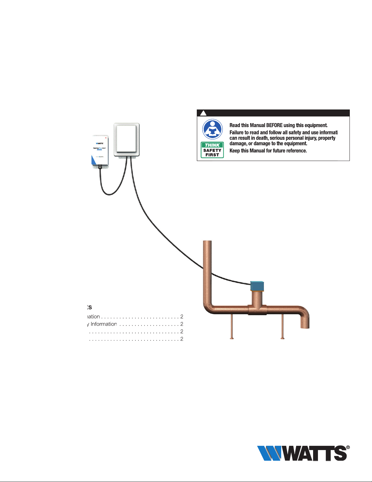
Read this Manual BEFORE using this equipment.
Failure to read and follow all safety and use information
can result in death, serious personal injury, property
damage, or damage to the equipment.
Keep this Manual for future reference.
. . . . . . . . . . . . . . . . . . . .
Maintenance Manual
SentryPlus™ Alert
Universal Upgrade Kit
!
WARNING
Read this Manual BEFORE using this equipment.
Failure to read and follow all safety and use information
can result in death, serious personal injury, property
damage, or damage to the equipment.
Keep this Manual for future reference.
IOM-UPGRADEKIT-SentryPlusAlert
Table of Contents
Important Safety Information . . . . . . . . . . . . . . . . . . . . . . . . . . 2
Understanding Safety Information . . . . . . . . . . . . . . . . . . . . 2
Description . . . . . . . . . . . . . . . . . . . . . . . . . . . . . . . . . . . . . . . 2
List of Parts. . . . . . . . . . . . . . . . . . . . . . . . . . . . . . . . . . . . . . . 2
Required Tools and Materials for Installation . . . . . . . . . . . . . . 2
Installation and Operation . . . . . . . . . . . . . . . . . . . . . . . . . . . . 3
ISolenoid Operation
(For Existing LFF113RFP Installations Only) . . . . . . . . . . . . . 3
Installing the Flow Sensor (Backflow Upgrade Kit Only) . . . . 3
Wiring/Retrofitting the junction box . . . . . . . . . . . . . . . . . . . 4
Installing the Wireless Node . . . . . . . . . . . . . . . . . . . . . . . . . 6
Registering Your Device and Alert Configuration . . . . . . . . . . . 7
Start-up Instructions . . . . . . . . . . . . . . . . . . . . . . . . . . . . . . . . 8
Warranty . . . . . . . . . . . . . . . . . . . . . . . . . . . . . . . . . . . . . . . . . 8
Page 2
Important Safety Information
Description
!
WARNING
To avoid death, serious personal injury, property damage,
or damage to the equipment:
• Learn how to properly and safely use the equipment
BEFORE installing, setting up, using, or servicing.
• Keep the manual available for easy access and future
reference.
• Replace missing, damaged, or illegible manual and
product labels.
• Read the manual and all product labels and follow all
safety and other information.
• Replacement manuals available at Watts.com.
Understanding Safety Information
This safety-alert symbol is
shown alone or used with
!
a signal word (DANGER,
WARNING, or CAUTION). A
pictorial and/or safety message to identify hazards and
alert you to the potential for
death or serious personal
injury.
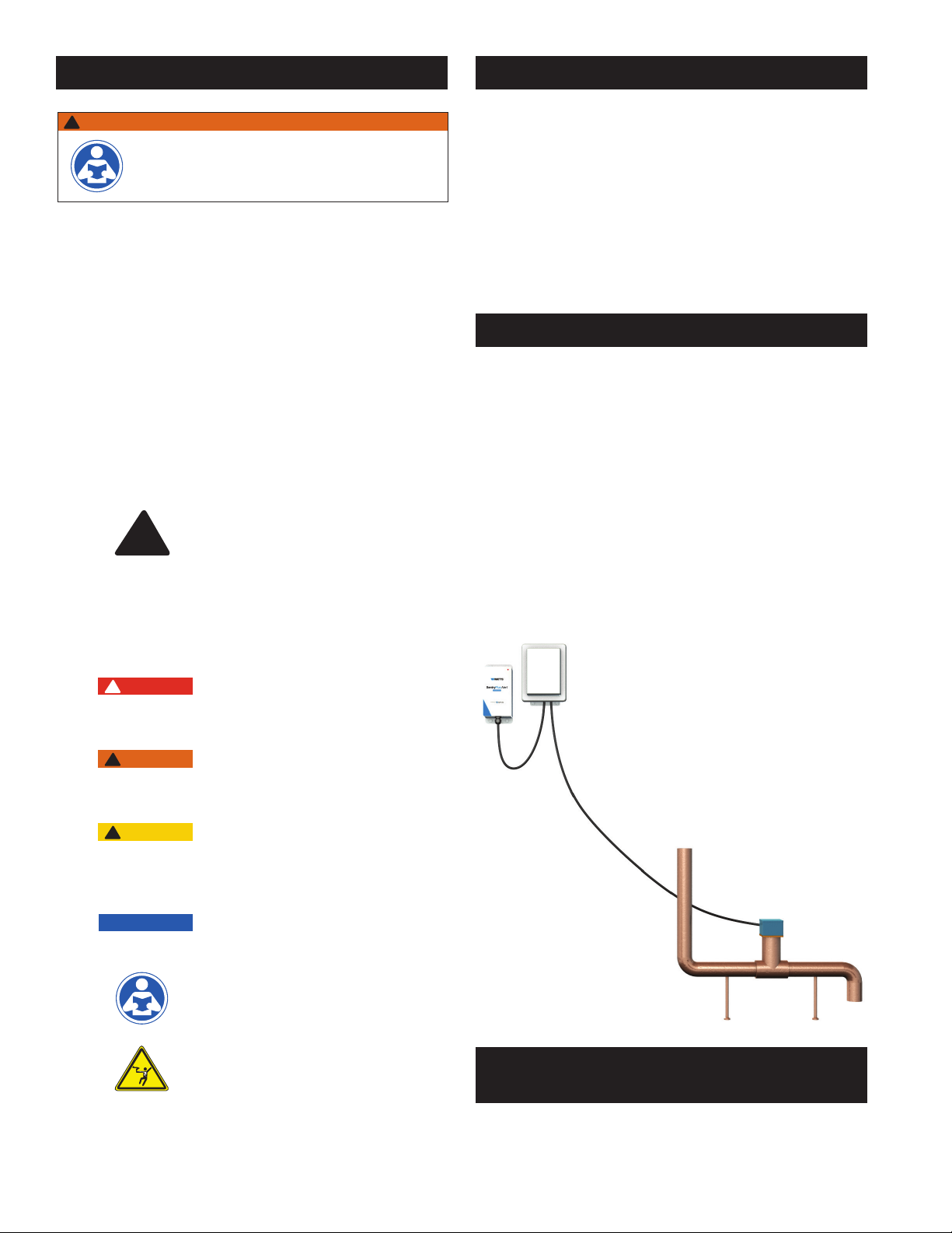
• SentryPlus™ Alert Technology Universal Upgrade Kit detects
catastrophic discharge from the relief valve of an RPZ
(Reduced Pressure Zone) backflow preventer that can cause
flooding due to excessive discharge and/or a blocked/undersized floor drain
• Wirelessly issues multi-channel alerts (call, text, email)
• Can be installed without taking equipment offline
• Can be installed with any existing RPZ backflow preventer
• Can be used to upgrade an existing Watts LFF113RFP ACV to
support SentryPlus Alert Technology
List of Parts
There are two types of SentryPlus Alert Technology Universal
Upgrade Kits.
For existing 113RFP Flood Protection ACV upgrades, the kit
consists of following:
• Smart Electronics Junction Box (JB113)
• Wireless Node (WN113)
For existing Backflow RPZ upgrades, the kit consists of
following:
• Smart Electronics Junction Box (JB113)
• Wireless Node (WN113)
• Flow Sensor (FS99)
• 2" Tee (PVC) with NPTF threaded end connections to mount
FS99 Flow Sensor
DANGER
!
!
WARNING
!
CAUTION
NOTICE
2
Identifies hazards which, if not
avoided, will result in death or
serious injury.
Identifies hazards which, if not
avoided, could result in death
or serious injury.
Identifies hazards which, if not
avoided, could result in minor
or moderate injury.
Identifies practices, actions,
or failure to act which could
result in property damage or
damage to the equipment.
This pictorial alerts you to the
need to read the manual.
This pictorial alerts you to
electricity, electrocution, and
shock hazards.
Required Tools and
Materials for Installation
❏ Small Phillips head screwdriver
❏ Screws to mount Wireless Node; holes are 0.27" diameter.
Select screws based on your application conditions.
Page 3
Installation and Operation
Solenoid Operation
(For Existing LFF113RFP Installations Only)
The Solenoid is prewired to the existing Junction Box, and must
be rewired by a certified electrician. The solenoid is equipped
with a Solenoid Bypass valve (normally closed) which manually
closes the Main Valve when engaged.
Opening the Solenoid Bypass Valve pressurizes the Main Valve
cover as indicated by Pressure Gauge, closing the Main Valve.
Closing Solenoid Bypass Valve and opening the Manual Reset
Ball Valve returns the Main Valve to the full open position.
Pressure Gauge returns to zero when the Main Valve is fully
open.
NOTE: Manual Reset Ball Valve must be closed for normal
operation.
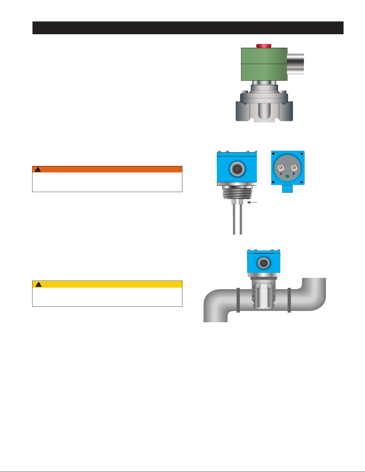
Installing the Flow Sensor
(Backfl ow Upgrade Kit Only)
!
WARNING
Certified electrician to connect main power and Flow Sensor to
Junction Box.
Front View
Top View with
Cover Removed
The Flow Sensor is installed in the discharge piping from the
RPZ relief valve. If the Flow Sensor senses water in the discharge piping, it will signal the Junction Box to close the valve.
Installation Notes
1. Install the supplied tee for the Flow Sensor in the RPZ discharge line in the HORIZONTAL position as shown below.
2. Cut Sensor Probes to length. The ends of the Sensor Probes
should be located between
eter from the pipe bottom. The probes MUST NOT BE less
than ¼" from the pipe wall.
3. Install Flow Sensor in tee, again ensuring that it is in the
HORIZONTAL position as shown below.
!
CAUTION
Ensure Sensor Probes do not contact pipe bottom or sides.
1
⁄3 and 1⁄2 of the pipe’s inner diam-
To Floor Drain
2" NPT
From RPZ Relief
Valve (with Air Gap)
Sensor Probes
Installed
3
Page 4

Installation and Operation
Wiring/Retrofi tting the junction box
Wireless Node
Cellular
Connection
to Internet
Wired to
Terminals
7 & 8
AC Power
Adapter
PROG
CN2
POWER
CELLULAR
loT
1
FLOOD
2
TESTRESET
FLOOD
FLOOD
GND
+12Vdc
Junction Box
Relay with Red
LED Indicator
11
N 65
L1
Incoming
Power
120V/1PH
1 2
Flow
Sensor
Probes
15
10 20
5 25
0 30
SEC
223344556677
3 4
Solenoid
Remote
Valve
Trip
Indication
Power
Remote
Trip
Indication
Wired to
Terminals
3 & 4
UP
88
87
Wired to
Terminals
1 & 2
120Vac
Power
BMS
The Junction Box is valve-mounted, but includes brackets for wall mounting.
!
CAUTION
When retrofitting an existing Model 113RFP Flood Protection ACV,
disconnect the electrical power before retrofitting the old Junction
Box to the new one.
NOTICE
During the retrofitting process on the 113RFP, the system
will not be monitoring for flood detection or protection..
Wiring the Junction Box
!
WARNING
Ensure that all power supply to the Junction Box is turned
off before making any connections to the Junction Box.
Failure to do so may result in electrocution, personal
injury, and /or death.
For Existing LFF113RFP Installations Only
• After removal of power from the circuit, disengage the
wiring from:
o Main terminals inside Junction Box
o Terminals 1 and 2 (Flow Sensor)
o Terminals 3 and 4 (Solenoid)
o Terminals 5 and 6 (remote trip indicator, if wired)
• Remove the Junction Box from the ACV or wall mount
• Replace the Junction Box with the new, upgraded Junction
Box. The physical dimensions of the new Junction Box are
identical to older units and can be mounted at the same
location.
• The solenoid valve must be rewired into the new junction box
using terminals 3 and 4. If needed, the connection can be
extended by using similar gauge extension wire and a terminal
box. The solenoid must be rewired by a certified electrician.
4
For All Installations
• Connect the Flow Sensor to the Junction Box using terminals
1 and 2.
• Connect to a Building Management System or alarm for
remote indications of a continuous water discharge using terminals 5 and 6.
• Connect to the Wireless Node using terminals 7 and 8.
NOTICE
• The terminal block accepts 10-22 AWG.
• Terminals 5 and 6 have 120V, 10A maximum.
• The Junction Box voltage is 120V.
• The Sensor Probe voltage is 120VAC, 1.5mA.
• The terminal block has a less than 1 amp draw.
Page 5

Installation and Operation
Adjusting the Time Delay
• Adjust the time delay to avoid alert / valve closure due to intermittent or nuisance relief valve discharge. The delay is adjustable from 0 seconds to over 1 hour.
• Adjust the time delay by using the delay adjustment dial in the
Junction Box.
• Use a small Phillips head screwdriver to adjust either the range
selector (0-6, 0-12, 0-30, 0-60) on the left side or the unit
selector (0.1 sec, sec, min, hr) on the right side.
• Increase the time delay by adjusting the dial clockwise;
decrease the time delay by adjusting the time delay counterclockwise.
• Recommended adjustment delay is 30-60 seconds. However,
the ideal set point can vary widely depending on the product
application, including drain size, location, backflow preventer,
water pressure, and tolerance for discharge.
Range selector
(0-6, 0-12, 0-30, 0-60)
RANGE SELECTION UNIT SELECTION
0.1 sec Sec Min Hrs
0-6 0.05-0.6s 0.5-6s 0.5-6min 0.5-6hr
0-12 0.1-1.2s 1-12s 1-12min 1-12hr
0-30 0.25-3s 2.5-30s 2.5-30min 2.5-30hr
0-60 0.5-6s 5-60s 5-60min 5-60hr
Unit selector
(0.1s, sec, min, hrs)
5
Page 6

Installation and Operation
Installing the Wireless Node
!
WARNING
Ensure all power supply to the Wireless Node is turned
off before making any connections to the Wireless Node.
Failure to do so may result in electrocution, personal
injury, and/or death.
1. Identify preferred location for mounting Wireless Node. The
Wireless Node must be located away from large metal components and structures that may block the cellular signal. In
addition, the cellular antenna is located on the inner sidewall
of the enclosure (11). When mounting, ensure that this side
of the device is away from any walls, wires, pipes, or other
obstructions, especially anything metallic.
2. Before mounting, plug in the Wireless Node to ensure that
a connection can be made in the preferred location. Once
plugged in, the device will automatically go through a startup process. A cellular connection has been made if, after the
start-up process, the Cellular LED (8) is a steady blue. If it is
blinking, there is a poor connection, and if it is off, there is
no connection. If there is a poor or no connection, identify a
new location for mounting.
3. Unplug the Wireless Node from the power supply.
4. Mount the Wireless Node in the identified location using the
four 0.27" diameter mounting holes (13). Screws are not
included.
5. Route wires from terminals 7 and 8 of the Junction Box
through the wiring gland (12) and connect to the Wireless
Node at the "Flood" screw terminal (2). Polarity does not
matter. Six feet of wire is supplied with the unit, but the
Wireless Node can be located up to 100 feet away from
the Junction Box. If additional wire is used. it must meet the
required rating for the Junction Box (300V, 16-24 AWG).
6. Route wires for included 12VDC power supply through the
wiring gland (12) and connect to the Wireless Node at the
appropriate screw terminal (1). Polarity must be correct or
the Wireless Node will not operate.
7
8
9
10
11
6
5
4
3
2
1
13
13
12
!
CAUTION
Use only the provided power supply as other power supplies may not
meet the rating and specifications for this device.
7. Tighten the wiring gland (12) to prevent water or dust from
entering the Wireless Node.
8. Connect the power supply to the Wireless Node and
Junction Box.
6
Page 7

Installation and Operation
Wireless Node Operation
1. Start-Up – Upon start-up, the Power LED (7) will light up
a steady green to indicate power is supplied. The Wireless
Node will automatically go into its start-up sequence. During
the start-up sequence, the light over the Program button
(5) will begin as solid white and then change to a blinking
green, indicating the Wireless Node is searching for a cellular connection. Once a cellular connection is established, the
Program button light will start blinking cyan, indicating that
the Wireless Node is connecting to the Cloud. Once a Cloud
connection is established, the Program button light will blink
rapidly for a few seconds, and then shut off. The Cellular
LED (8) and IoT LED (9) should both be a solid blue.
2. Cellular Connection – Once the start-up sequence is
completed, the Cellular LED will be a steady blue if there is
a good connection. It will blink if there is a poor connection.
There will be no color if there is no connection.
3. IoT Connection – If there is a Cloud connection, the IoT
LED will be a steady blue. There will be no color if it is off.
NOTICE
If there is no Cloud connection, then notifications will not be
sent to the user via Syncta.
4. Flood LED – If a flood event occurs, the Flood LED (10)
will be a steady orange. It will remain on so long as there
is a flood condition.
5. Test Button – When Cellular and Cloud connections
have been made, a test message can be sent through the
Syncta app by pressing the Test Button (3).
6. Reset Button – You can reset the Wireless Node and
restart the start-up sequence by pressing the Reset button (4). This will cause all on-going operations to cease.
7. Program Button – The Program button (5) should not be
pressed and is for factory use only.
Registering Your Device and Alert Confi guration
1. Using a smart phone or tablet,
scan the QR code on the side
on the Wireless Node, or go to
https://connected.syncta.com.
2. When prompted, enter the
Device ID. The Device ID is a
15-digit number found beneath
the QR code on the side of the
Wireless Node.
3. Follow onscreen prompts to
create a Syncta account, or
if you are an existing Syncta
user, log in to your account.
The device can be registered
to multiple accounts.
4. Once the device is registered to your account, follow
prompts to add notifications.
To manage alerts, login to your
account on Syncta.com.
7
Page 8

Start-up Instructions
1. Open Junction Box. Apply power and observe the Electric
Relay Control.
2. Pour adequate amount of water into RPZ Relief Valve Air
Gap until the red LED indicator light on the Electrical Relay
illuminates / flashes. This indicates the Flow Sensor is properly installed and is sensing water in the discharge piping.
3. Trap water in discharge piping and observe red LED on
Electrical Relay. A message will be sent via Syncta when
the duration of the time delay elapses, observe Flood LED
(10) to ensure activation after the time delay. Adjust time
delay to customer/project specifications. When connected to a LFF113RFP ACV, solenoid will energize and valve
will go closed after time delay elapses. To manually reset
valve, refer to step four in the Start-Up Instructions of the
LFF113FP Installation, Operation, and Maintenance Manual,
available on watts.com
4. For final test simulate actual RPZ Relief Valve discharge
and observe floor drain for excessive pooling or flooding.
Re-adjust time delay and Adjustable Closing Speed (when
used with a LFF113RFP ACV) control as needed to achieve
desired alert/valve closure time.
Valve Travel
VALVE SIZE - INCHES 1 1/4 1 1/2 2 2 1/2 3 4 6 8 10
Travel - Inches
3
⁄8
3
⁄8
3
⁄8
5
⁄8
3
⁄4 1 11⁄2 2 21⁄2
Valve Cover Chamber Capacity
VALVE SIZE - INCHES 1 1/4 1 1/2 2 2 1/2 3 4 6 8 10
fl.oz. 4 4 4 10 10 22 70
U.S. Gal 1
Limited Warranty: Watts (the “Company”) warrants each product to be free from defects in material and workmanship under normal usage for a period of one year from the date of original shipment.
In the event of such defects within the warranty period, the Company will, at its option, replace or recondition the product without charge.
THE WARRANTY SET FORTH HEREIN IS GIVEN EXPRESSLY AND IS THE ONLY WARRANTY GIVEN BY THE COMPANY WITH RESPECT TO THE PRODUCT. THE COMPANY MAKES NO OTHER
WARRANTIES, EXPRESS OR IMPLIED. THE COMPANY HEREBY SPECIFICALLY DISCLAIMS ALL OTHER WARRANTIES, EXPRESS OR IMPLIED, INCLUDING BUT NOT LIMITED TO THE IMPLIED
WARRANTIES OF MERCHANTABILITY AND FITNESS FOR A PARTICULAR PURPOSE.
The remedy described in the first paragraph of this warranty shall constitute the sole and exclusive remedy for breach of warranty, and the Company shall not be responsible for any incidental, special
or consequential damages, including without limitation, lost profits or the cost of repairing or replacing other property which is damaged if this product does not work properly, other costs resulting
from labor charges, delays, vandalism, negligence, fouling caused by foreign material, damage from adverse water conditions, chemical, or any other circumstances over which the Company has no
control. This warranty shall be invalidated by any abuse, misuse, misapplication, improper installation or improper maintenance or alteration of the product.
Some States do not allow limitations on how long an implied warranty lasts, and some States do not allow the exclusion or limitation of incidental or consequential damages. Therefore the above
limitations may not apply to you. This Limited Warranty gives you specific legal rights, and you may have other rights that vary from State to State. You should consult applicable state laws to
determine your rights. SO FAR AS IS CONSISTENT WITH APPLICABLE STATE LAW, ANY IMPLIED WARRANTIES THAT MAY NOT BE DISCLAIMED, INCLUDING THE IMPLIED WARRANTIES OF
MERCHANTABILITY AND FITNESS FOR A PARTICULAR PURPOSE, ARE LIMITED IN DURATION TO ONE YEAR FROM THE DATE OF ORIGINAL SHIPMENT.
1
⁄4 21⁄2
USA: T: (978) 689-6066 • F: (978) 975-8350 • Watts.com
Canada: T: (905) 332-4090 • F: (905) 332-7068 • Watts.ca
Latin America: T: (52) 81-1001-8600 • Watts.com
IOM-UPGRADEKIT-SentryPlusAlert 1905 EDP# 1915433 © 2019 Watts
 Loading...