

Page 1
Instructions for Installing
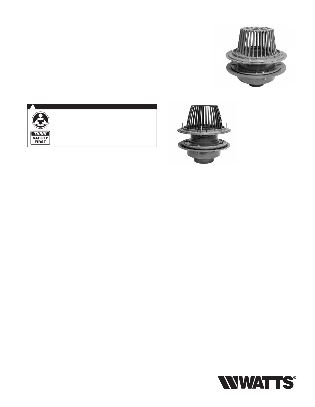
RD‑300‑AC/RD‑300‑AE
RD-300-AC Adjustable Extension
Compression Seal Roof Drain And
RD-300-AE Adjustable Extension
Threaded Seal Roof Drain
!
WARNING
Read this Manual BEFORE using this equipment.
Failure to read and follow all safety and use information
can result in death, serious personal injury, property
damage, or damage to the equipment.
Keep this Manual for future reference.
IS-WD-RD-300-AC/AE-CAN
RD-300-AC
Installation Guidelines
RD-300-AE
General Note: Please consult all local plumbing codes before installing
Watts roof drains.
Introduction
Building roofs are effected by all types of weather and changes in the atmosphere.
Roof expansion and contraction are caused by both freezing and thawing of standing
water in and on roof areas. Thorough and effective roof drainage systems can
eliminate damage to both the roof and substructure of a building.
Watts has an extensive line of roof drains and accessories engineered and designed to
meet the needs and concerns of our customers.
Watts RD-300-AC/RD-300-AE allow the contractor to adjust the roof drain to the
desired height during installation and after installation. They offer both a compression
seal and a threaded seal option.
Concerns When Selecting the Proper Roof Drain
Style and Type of Roof Construction
Overall Size and Pitch of Roof
Efcient Location of Drains
Roof Load & Safety Requirements
Rate of Drainage Needed
Page 2
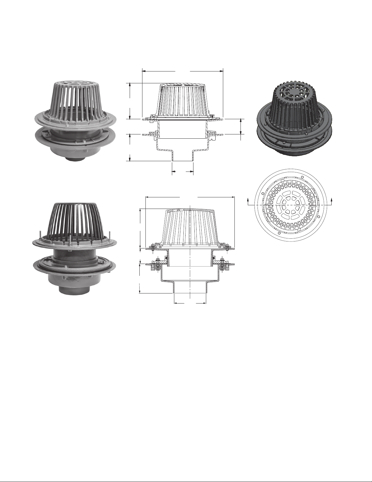
7 1/4"
Size
" (79) Max.
1" (25) Min.
16 5/8"(422)
(187)
RD-300-AC
16 5/8"
(422)
5 1/2"
(140)
Pipe
3 1/8
RD-300-AE
A
8"
(203)
4"(102) Max.
2"(51) Min.
5 1/2"
(140)
A
Pipe Size
Note: The RD-300-AC & RD-300-AE offer several options that change the installation
process.
The -F Deck Flange/Adjustable Extension option is a metal ange that installs directly into the
roof with screws . It has metal rods that extend upward and hold the lower body of the drain in
place. This creates an extension in instances where materials such as insulation or gravel create
a barrier between the roof and drain. Once installed, the drain may require a rubber membrane to
direct the ow of the water into the drain.
Drains ordered with the -B Sump Receiver allow lower body ange to set ush against the roof.
The sump receiver is installed into the lower part of the roof with a thin metal ange that screws into
the top of the roof. The metal ange is tapered to a hole in the center that allows the lower body of
the drain to fully recess into the roof. The lower body ange is equipped with screw holes that allow
the drain to sit ush against the roof when tightened.
The "F" ange option allows for adjustable extension and no need for reinforcement, while the "B"
sump receiver allows for installation ush with the roof. Make sure you have ordered correctly before
preparing for installation.
Page 3

The -D Underdeck Clamp option creates an extension that lowers into the roof with clamps that
hold the drains lower body.
The -GSS Stainless Steel Ballast Guard is a 2" inch stainless steel band that sits on top of the
lower body ange. It has holes that allow the water to ow into the lower body while holding debris
out.
The -R 2" External Water Dam option is a 2" stainless steel band with holes that sits on the top of
the dome ange. It also holds debris out while allowing the water to ow through the holes.
-GSS Stainless Steel Ballast Guard
-R 2" External Water Dam
Parts are the same, but install
differently.
The -W Adjustable Internal Water Dam option is a pipe inserted in the middle of the roof drain
that holds water back until it reaches a certain height on the roof.
Insulation
Slab Or Deck
Dome
Flashing Clamp
Adjustable Extension
Flashing
Compression Flange
Compression Gasket
B15 Body
Page 4

Typical Installation
Create an opening in the roof to accommodate the drain assembly
RD-300-AC
With Sump Receiver 18"(457)
Incorrect installation occurs when the circular hole is cut off center of the leader .
pipe extending upwards in the roof.
Step 1:
Place gasket on drain body and align holes.
Step 2:
Place clamps onto gasket, align holes and
insert (4) 5/16-18 screws, do not tighten at
this point
"F" Deck Flange Installation Instructions
Step 4:
Place dome onto top
collar and turn slightly
to lock in place.
Step 3:
Insert adjustable top collar and adjust to
desired height. (Wood blocks, plastic pipes
etc... cut to the correct height on each side
will ease the installation process.)
Tighten (4) screws.
The use of a 10 ga. zinc plated steel ange helps to reduce the risk of a crooked or
off-set of the leader pipe. It enables the roof drain to be adjusted to insulation
height and is recessed in the center to accept the roof drain body and eliminate
the pooling of water in and around the drain. The ange eliminates the need for
reinforcement of the roof drain.
Place the ange over the opening. Flange may be fastened to the roof deck if desired.
Line the ashing clamp on the body of the roof drain up with holes in the ange and
secure with screws. (provided)
Page 5

Adjust the roof drain to the height needed with the threaded rods included in the
hardware kit. Tighten the drain at desired height.
The ductile iron dome is impact resistant and nished with standard grey epoxy
coating.
Place the ductile iron dome over the drain body and align the holes for the screws
on both the ashing clamp and the dome.
Place the screws into the holes and tighten until snug.
Sump Receiver Installation Instructions
Place the sump receiver over the roof opening making sure that the recessed area
will accommodate the roof drain body while aligning with the leader pipe.
Lower the drain body into the opening and screw the deck ange into the sump
receiver and roof.
Insert the adjustable top collar to the desired height.
Position the roof dome over the drain and align the holes with the ashing clamp on
the drain body.
Place screws into the holes and tighten until dome ts snug against the drain body.
RD-300-AE Adjustable Threaded Extension
The RD-300-AE installs like the RD-300-AC except that the adjustable top collar
is threaded instead of having a compression seal. A bead of petroleum jelly will need
to be applied before screwing the top collar into the lower body. The threads are used
to adjust top to desired height. Place dome onto top collar and turn slightly to lock in
place.
"F" Deck Flange Installations and Sump Receiver instructions will also be the same.
Use petroleum jelly for threading the top collar to the desired height.
Options for the RD-300-AE are the same.
Limited Warranty: Watts Regulator Co. (the “Company”) warrants each product to be free from defects in material and workmanship under normal usage for a period of one year from the date of
original shipment. In the event of such defects within the warranty period, the Company will, at its option, replace or recondition the product without charge.
THE WARRANTY SET FORTH HEREIN IS GIVEN EXPRESSLY AND IS THE ONLY WARRANTY GIVEN BY THE COMPANY WITH RESPECT TO THE PRODUCT. THE COMPANY MAKES NO OTHER
WARRANTIES, EXPRESS OR IMPLIED. THE COMPANY HEREBY SPECIFICALLY DISCLAIMS ALL OTHER WARRANTIES, EXPRESS OR IMPLIED, INCLUDING BUT NOT LIMITED TO THE IMPLIED
WARRANTIES OF MERCHANTABILITY AND FITNESS FOR A PARTICULAR PURPOSE.
The remedy described in the first paragraph of this warranty shall constitute the sole and exclusive remedy for breach of warranty, and the Company shall not be responsible for any incidental, special
or consequential damages, including without limitation, lost profits or the cost of repairing or replacing other property which is damaged if this product does not work properly, other costs resulting
from labor charges, delays, vandalism, negligence, fouling caused by foreign material, damage from adverse water conditions, chemical, or any other circumstances over which the Company has no
control. This warranty shall be invalidated by any abuse, misuse, misapplication, improper installation or improper maintenance or alteration of the product.
Some States do not allow limitations on how long an implied warranty lasts, and some States do not allow the exclusion or limitation of incidental or consequential damages. Therefore the above
limitations may not apply to you. This Limited Warranty gives you specific legal rights, and you may have other rights that vary from State to State. You should consult applicable state laws to
determine your rights. SO FAR AS IS CONSISTENT WITH APPLICABLE STATE LAW, ANY IMPLIED WARRANTIES THAT MAY NOT BE DISCLAIMED, INCLUDING THE IMPLIED WARRANTIES OF
MERCHANTABILITY AND FITNESS FOR A PARTICULAR PURPOSE, ARE LIMITED IN DURATION TO ONE YEAR FROM THE DATE OF ORIGINAL SHIPMENT.
USA: Tel: (800) 338-2581 • Fax: (828) 248-3929 • Watts.com
Canada: Tel: (905) 332-4090 • Fax: (905) 332-7068 • Watts.ca
Latin America: Tel: (52) 81-1001-8600 • Watts.com
IS-WD-RD-300-AC/AE-CAN 1848 EDP# 1915427 © 2018 Watts
Page 6

Instructions pour
l’installation du
RD‑300‑AC/RD‑300‑AE
RD-300-AC Égout de toit à extension
ajustable avec joint de compression
et RD-300-AE Égout de toit à
extension ajustable avec letage
!
AVERTISSEMENT
Lisez ce manuel AVANT d’utiliser cet équipement.
Le non-respect de toutes les instructions de sécurité
et d’utilisation de ce produit peut endommager ce
LA SÉCURITÉ
AVANT
TOUT
produit ou entraîner d’autres dommages matériels,
desblessures graves ou la mort.
Conservez ce manuel pour référence ultérieure.
IS-WD-RD-300-AC/AE-CAN
RD-300-AC
Directives d’installation
RD-300-AE
Remarque générale: veuillez consulter tous les codes locaux de
plomberie avant l’installation des égouts de toit de Watts.
Introduction
Les toits des bâtiments sont affectés par tous les types de météos et les changements
atmosphériques. L’expansion et la contraction du toit sont causées par le gel et le dégel
de l’eau dormante sur et dans les zones des toits. Des systèmes de drainage complets
et efcaces peuvent éliminer le dommage au toit et à la sous-structure d’un bâtiment.
Watts a une vaste gamme d’égouts de toit et d’accessoires spécialement conçus
pour répondre aux besoins et préoccupations de nos clients.
Watts RD-300-AC/RD-300-AE permet à l’entrepreneur de régler l’égout de toit à la
hauteur désirée, lors de l’installation et après. Les deux offrent une option par joint de
compression et par joint leté.
Préoccupations lors de la sélection de l’égout de toit approprié
Style et type de construction du toit
Taille globale et pente du toit
Emplacement efcace des égouts
Charge du toit et exigences en matière de sécurité
Taux de drainage exigé
Page 7

7 1/4"
Size
16 5/8"(422)
71/4po
(187)
(187mm)
51/2po
5 1/2"
(140mm)
(140)
8po
8"
(203mm)
(203)
RD-300-AC
165/8po
16 5/8"
(422mm)
(422)
Pipe
Taille du
tuyau
RD-300-AE
165/8po (422mm)
31/8po (79mm) max.
3 1/8" (79) Max.
1po (25mm) min.
1" (25) Min.
A
A
5po (102mm) MAX.
4"(102) Max.
2"(51) Min.
2po (51mm) MIN.
51/2po
5 1/2"
(140mm)
(140)
Taille du tuyau
Pipe Size
Remarque: le RD-300-AC et le RD-300-AE offrent plusieurs options qui changent le
processus d’installation.
L’option de bride de fixation/d’extension ajustable-F est une bride en métal qui s’installe
directement dans le toit avec des vis. Il a des tiges de métal qui s’étirent vers le haut et tiennent la
partie inférieure de l’égout en place. Cela crée une extension pour les cas où les matériaux, comme
l’isolation ou le gravier, créent une barrière entre le toit et l’égout. Une fois installé, l’égout pourrait
nécessiter une membrane en caoutchouc pour diriger le débit d’eau dans l’égout.
Les égouts commandés avec un récepteur de puisard -B permettent de régler la partie inférieure
de la bride à plat contre le toit. Le récepteur de puisard est installé sur la partie inférieure du toit
à l’aide d’une bride mince en métal qui se visse dans le dessus du toit. La bride en métal est en
forme conique vers un trou dans le centre qui permet à la partie inférieure de l’égout de se loger
entièrement dans le toit. La bride de la partie inférieure est munie de trous de vis qui permettent à
l’égout d’être placé à plat contre le toit lorsqu’elles sont serrées.
L’option de bride «F» permet une extension ajustable, sans nécessiter un renforcement, alors
que le récepteur de puisard «B» permet une installation au ras de la surface du toit. Assurez-vous
d’avoir commandé correctement avant de préparer l’installation.
Page 8

L’option de collier-D pour la surface inférieure crée une extension qui s’abaisse dans le toit avec
des colliers qui tiennent la partie inférieure de l’égout.
Le protège-ballast en acier inoxydable -GSS est une bande en acier inoxydable de 2po
(51mm) qui est placée sur le dessus de la bride de la partie inférieure. Il comprend des trous qui
permettent à l’eau de couler dans la partie inférieure, tout en empêchant l’entrée de débris.
L’option de seuil filtre externe de 2po (51mm) -R est une bande en acier inoxydable de 2po
(51mm) avec des trous qui est placée sur le dessus de la bride du dôme. Il empêche aussi l’entrée
des débris tout en permettant la circulation de l’eau par les trous.
Protège-ballast en acier inoxydable -GSS
Seuil filtre externe de 2po (51mm) -R
Les pièces sont les mêmes, mais s’installent
différemment.
L’option de seuil filtre interne réglable -W est un tuyau inséré dans le milieu de l’égout de toit qui
retient l’eau jusqu’à ce qu’il atteigne une hauteur précise sur le toit.
Collier de la bande de recouvrement
Bande de recouvrement
Insulation
Isolation
Slab Or Deck
Dalle ou surface
Joint d’étanchéité de compression
Flashing Clamp
Adjustable Extension
Extension ajustable
Flashing
Compression Flange
Bride de compression
Compression Gasket
Dome
Dôme
B15 Body
Partie B15
Page 9

Installation typique
Créer une ouverture dans le toit pour recevoir l’ensemble de l’égout
RD-300-AC
Avec récepteur de puisard de 18po (457mm)
Une installation inappropriée se produit lorsque le trou circulaire n’est pas coupé au
centre du tuyau principal qui se prolonge dans le toit.
Étape 1:
Placer le joint d’étanchéité sur le corps de
l’égout et aligner les trous.
Étape 2:
Placer les colliers sur le joint d’étanchéité,
aligner les trous et insérer les (4)vis5/1618; ne pas les serrer à ce point.
Étape3:
Insérer le collier supérieur ajustable et
l’ajuster à la hauteur désirée. (Des blocs de
bois, des tuyaux en plastique, etc., coupés
à la hauteur appropriée de chaque côté
faciliteront le processus d’installation.)
Serrer les (4)vis.
Étape4:
Placer le dôme sur le
collier supérieur et le
tourner légèrement
pour le verrouiller.
Instructions d’installation avec bride de fixation «F»
L’utilisation de bride en acier zingué de calibre10 aide à réduire le risque d’un tuyau
principal croche ou décalé. Cela permet d’ajuster l’égout de toit à la hauteur de
l’isolation, et est encastré au centre an d’accepter le corps de l’égout de toit et
éliminer l’accumulation de l’eau dans le drain et autour. La bride élimine la nécessité
de renforcer l’égout de toit.
Placer la bride par-dessus l’ouverture. La bride peut être serrée à la surface du toit, si
désiré. Aligner le collier de la bande de recouvrement sur le corps de l’égout de toit
avec les trous dans la bride et xer avec des vis (fournies).
Page 10

Ajuster l’égout de toit à la hauteur nécessaire à l’aide des tiges letées incluses dans
la trousse de quincaillerie. Serrer l’égout à la hauteur désirée.
Le dôme en fer ductile est résistant aux chocs et ni d’un revêtement en époxy
grisstandard.
Placer le dôme en fer ductile par-dessus le corps de l’égout, aligner les trous pour les
vis sur le collier de la bande de recouvrement et le dôme.
Placer les vis dans les trous et les serrer.
Instructions d’installation du récepteur du puisard
Placer le récepteur du puisard par-dessus l’ouverture du toit en s’assurant que la zone
encastrée acceptera le corps de l’égout de toit en l’alignant avec le tuyau principal.
Abaisser le corps de l’égout dans l’ouverture et visser la bride de xation dans le
récepteur du puisard et le toit.
Insérer le collier réglable à la hauteur voulue.
Placer le dôme de toit par-dessus l’égout et aligner les trous au collier de la bande de
recouvrement sur le corps de l’égout.
Placer les vis dans les trous et les serrer jusqu’à ce que le dôme soit bien serré contre
le corps de l’égout.
RD-300-AE Extension ajustable avec filetage
Le RD-300-AE s’installe comme le RD-300-AC, à l’exception du collier supérieur
ajustable qui est leté plutôt que muni d’un joint de compression. L’application d’un
ruban de gelée de pétrole sera nécessaire avant de visser le collier supérieur dans la
partie inférieure. Les letages sont utilisés pour ajuster le haut à la hauteur désirée.
Placer le dôme sur le collier supérieur et le tourner légèrement pour le verrouiller.
Les instructions pour installation de bride de surface «F» et récepteur de puisard
seront aussi les mêmes. Utiliser la gelée de pétrole pour le letage du collier supérieur
à la hauteur désirée.
Les options pour le RD-300-AE sont les mêmes.
Garantie limitée: Watts Regulator Co. (la «Société») garantit que chacun de ses produits est exempt de vice de matériau et de fabrication dans des conditions normales d’utilisation, pour une période
d’un an à compter de la date d’expédition d’origine. Si une telle défaillance devait se produire au cours de la période sous garantie, la Société aura à sa discrétion l’alternative suivante: le remplacement ou bien la remise en état du produit, sans frais pour le demandeur.
LA PRÉSENTE GARANTIE EXPRESSE EST LA SEULE ET UNIQUE GARANTIE, RELATIVE AU PRODUIT, FOURNIE PAR LA SOCIÉTÉ. LA SOCIÉTÉ NE FORMULE AUCUNE AUTRE GARANTIE, EXPRESSE
OU IMPLICITE. LA SOCIÉTÉ REJETTE AUSSI FORMELLEMENT PAR LA PRÉSENTE TOUTE AUTRE GARANTIE, EXPRESSE OU IMPLICITE, Y COMPRIS (SANS S’Y LIMITER) LES GARANTIES
IMPLICITES DE QUALITÉ MARCHANDE ET D’APTITUDE À UN USAGE PARTICULIER.
Le dédommagement précisé dans le premier paragraphe de cette garantie constitue la seule et unique alternative en cas de service demandé sous cette garantie. La Société ne pourra être tenue
responsable de dommages spéciaux ou indirects, incluant, sans s’y limiter: pertes de profit, coûts de réparation ou de remplacement des autres biens ayant été endommagés si ce produit ne fonctionne
pas correctement, autres coûts afférents aux frais de main-d’œuvre, de retards, de vandalisme, de négligence, d’engorgement causés par des corps étrangers, dommages causés par des propriétés
de l’eau défavorables, des produits chimiques, ou toute autre circonstance indépendante de la volonté de la Société. La présente garantie est déclarée nulle et non avenue en cas d’usage abusif ou
incorrect, d’application, d’installation ou d’entretien incorrects ou de modification du produit.
Certains États n’autorisent pas les limitations de durée d’une garantie tacite ni l’exclusion ou la limitation des dommages accessoires ou indirects. En conséquence, ces limitations pourraient ne pas
s’appliquer à votre cas. Cette garantie limitée vous confère des droits spécifiques, reconnus par la loi; vous pourriez également avoir d’autres droits, lesquels varient selon la loi en vigueur. Vous devez
donc prendre connaissance des lois applicables pour votre cas particulier. LA DURÉE DE TOUTE GARANTIE IMPLICITE PRÉVUE PAR LA LOI EN APPLICATION ET DEVANT DONC ÊTRE ASSUMÉE,
Y COMPRIS LES GARANTIES IMPLICITES DE QUALITÉ MARCHANDE ET D’APTITUDE À UN USAGE PARTICULIER, SERA LIMITÉE À UN AN À PARTIR DE LA DATE DE L’EXPÉDITION D’ORIGINE.
É.-U.: Tél.: (800) 338-2581 • Téléc.: (828) 248-3929 • Watts.com
Canada: Téléph.: (905) 332-4090 • Téléc.: (905)332-7068 • Watts.ca
Amérique latine: Tél.: (52)81-1001-8600 • Watts.com
IS-WD-RD-300-AC/AE-CAN 1848 EDP nº1915427 © 2018 Watts
 Loading...