

Page 1
Model
Number
Fittings
&
Valves
GPD Pump
(H.P.)
Recovery
(Adjustable)
Membrane
Size
Membranes
Feed Water
Required*
(GPM)
Typical
Rejection
Dimensions
Ship
Wt.
(Lbs.)
R14-01-1WM SS 1800 1 15%-75% 4" x 40" 1 2.5 98%
41"x51"x18"
200
R14-01-BWM Brass 1800 1 15%-75% 4" x 40" 1 2.5 98%
41"x51"x18"
200
R14-02-1WM SS 3600 1 25%-75% 4" x 40" 2 5 98%
41"x51"x18"
250
R14-02-BWM Brass 3600 1 25%-75% 4" x 40" 2 5 98%
41"x51"x18"
250
R14-03-1WM SS 5400 1.5 35%-75% 4" x 40" 3 7.5 98%
41"x51"x18"
300
R14-03-BWM Brass 5400 1.5 35%-75% 4" x 40" 3 7.5 98%
41"x51"x18"
300
*At 50% recovery.
Feed water connection 1" FNPT
Product water connection (1800 & 3600 GPD) 1/2" tube
Product water connection (5400 GPD) 5/8" tube
Reject water connection (all R14 models) 1/2" tube
Feed water pressure requirement (minimum) 10 PSIG
Drain requirement (maximum) 10 GPM
Electrical requirement 230v/60hz
Amps (1800 & 3600 GPD) 6
Amps (5400 GPD) 9
Part Number Description
R2353-SD Product water float switch
R2288 Whole house option*
*Includes 300 gallon tank, productwater float switch and repressurization
pump with built-in controls.
Specificati ons
Options
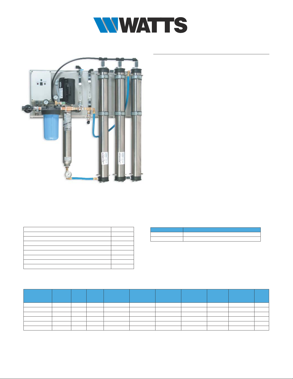
Models
R-14 wall-mounted systems
Three models for flow rates to 5400 GPD,
available with brass and stainless steel fittings.
Fully assembled and ready for installation.
Standard features
•
Stainless steel frame
•
Stainless steel pressure vessels
•
Pre-filter housing and cartridge, 10" Full-Flow
•
Webtrol®multi-stage centrifugal pump
•
Automatic inlet valve
•
Low-pressure shut-off with automatic restart
•
Tank level input
•
Pretreatment interlock input
•
Adjustable recycle line
•
Pre-filter pressure gauges
•
Pump discharge pressure gauge (liquid filled)
•
Flow meter for product water
•
Flow meter for reject water
•
Check valve for product water
•
Sample valve for product water
•
On / off switch
R14-03-BWM System
Notes: Performance specifications are based on 77°F feed water, 3 SDI or less, TDS below 1000 and pH of 8. Please see water temperature
conversion charts to determine actual production rate for each installation. Chlorine reduction and other pretreatment may be required.
Membrane rejection rates are based on membrane manufacturer's specifications. Pre-filter is Flow-Pro
®
FPMB-BB5-10 melt blown cartridge.
Systems are designed for use with municipal and well water.
WATER QUALITY & CONDITIONING PRODUCTS
®
Page 2
®
WATER QUALITY & CONDITIONING PRODUCTS
Introduction
Watts Reverse Osmosis (R/O) Systems are designed to provide the commercial
and industrial user with the most trouble free, cost effective and reliable form of
water treatment available, by providing every option necessary for a successful
installation.
Principles of Reverse Osmosis
Watts R/O systems employ thin film composite spiral wound membrane
elements for superior performance. To simply describe the process, pump
pressure is used to supply source water to reverse osmosis membranes. These
special membranes allow only high quality water to permeate them. In turn, they
reject metals, salts, ionic and organic impurities that are processed to waste.
Suspended solids are removed by pre-filters, which are standard components
on all Watts RO systems
.
Water temperature
Product water quality and production of any RO system is dependent on
pressure and temperature. Watts™ RO systems are rated at standard
conditions of 77˚F (25˚C), 60 psi (4.2 bar) inlet pressure and 1,000 TDS feed
water quality. Higher temperatures will result in more water passing through the
membranes and increased water production. As a rule, at given pressures and
TDS levels, for each one-degree change in water temperature the change in
water production is approximately 2%.
Water temperature Production Factor*
°F °C (Using thin film membranes)
40 4 0.48
50 10 0.60
60 16 0.73
70 21 0.88
77 25 1.00
80 27 1.06
90 32 1.26
*Percent of rated production.
Water pressure
Watts® commercial RO systems require a minimum of 10 psi feed pressure to
function properly. The maximum pressure is 90 psi, and a pressure regulator
must be utilized over 90 psi to reduce feed water pressure.
Feed / source water inlet requirements
The source water requirements shown below are essential for proper operation:
Note:
Pretreatment may be required if the above parameters are not met.
Failure to meet feed water requirements may foul membranes, void the warranty
and possibly make it necessary to down-rate performance.
All specifications listed are based on an average of 1,000 TDS feed water, 77°F
(25°C) temperature and 60 psi (4.2 bar) pressure. Typically, higher-pressure
differentials and higher temperatures increase water production and water
quality. Maximum pressure and temperature limits must be observed.
Factor Requirement
Hardness <1 grain per gallon
Free chlorine 0 ppm
T.D.S. <1,000 ppm
S.D.I. <5
pH 3-11
Iron <0.01 ppm
Silica <25 ppm
Manganese <0.05 ppm
Turbidity <1 NTU
Temperature 40°F - 95°F (4°C - 32°C)
Pressure 10 - 90 psi (2.8 - 5.6 bar)
Inlet feed water requirements
Distributed by:
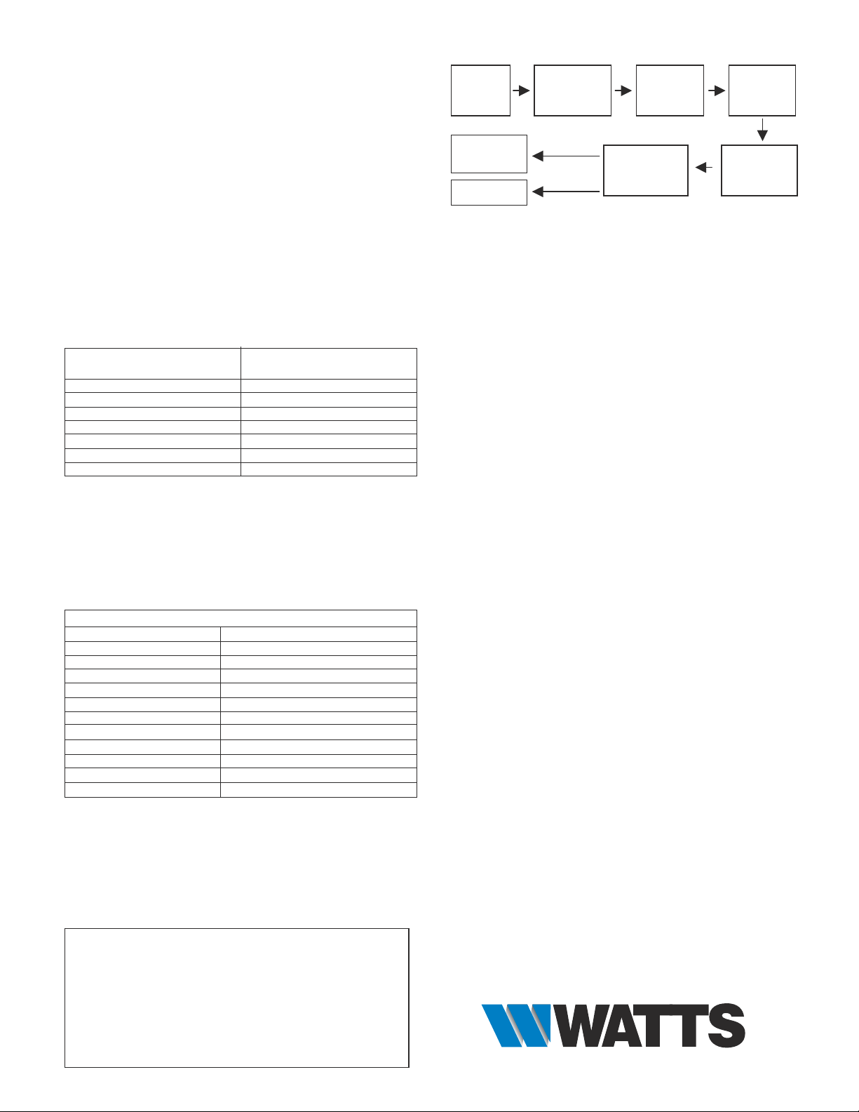
Feed
Water
Scale
Prevention
(Softener)
Chlorine
Removal
(Carbon)
Cartridge
Pre-Filter
High
Pressure
Pump
R/O
Membranes
Waste
Product
Water
General RO Process Diagram
1. System location
The RO system should be located on a level surface in an area sheltered from
sun, wind and rain. The temperature in this area should be maintained, and
should not fall below 35°F, nor greater than 95°F. If these limits are exceeded,
damage to components may result and the warranty may be considered void. It
is important to allow sufficient space around the unit so maintenance can easily
be performed.
2. Plumbing
The high-pressure pumps used require a continuous flow of water to the
system. Minimum feed pressure is 10 psi. Please see table, below for minimum
flow rates.
3. Feed water
Piping for feed water to the RO system should be either copper or plastic. Iron
and carbon steel pipe will increase the iron content of the raw feed water and
adversely affect the RO system's performance. Temperature of the feed water
must not exceed 95°F.
4. Product water (permeate) line connection
Connect the product water (permeate) line to the manifold on the back side of
the system. This line should not have valves and should run as directly as
possible to the storage tank.
5. Concentrate (waste) line connection
Connect the waste line (concentrate) to the manifold on the back side of the
system. The waste from the system should not have valves and should have an
air break between it and the building drain system. The tubing or piping used for
discharge of the concentrate should be run to an open drain in a free and
unrestricted manner.
6. Electrical
The customer must provide a properly sized electrical service.
Level controls
In most installations it is necessary to use the level switch connector wire to
install a level control or an electrical switch to turn the RO system on and off
based on the water level in the storage tank.
Pumps
Never let pumps run dry. Operating pumps without sufficient feed water will
cause damage. Feed pumps with filtered water only.
Pre-filtration
All Watts® RO systems come with particulate pre-filters to remove suspended
particles down to five (5) micron in size. Change pre-filter cartridges at least
every month or when there pressure differential of 10% or more that start-up
pressure differential with clean cartridges.
Limited warranty
Watts® Commercial Reverse Osmosis systems are warranted to the original
purchaser to be free of defects in material and workmanship for a period of one
year from date of shipment. Should defects occur, Watts will repair or replace
parts, which are defective. Shipping and labor costs are excluded for this limited
warranty, and these costs are the customer's responsibility. Normal wear,
accident, abuse, misuse, unauthorized alteration or repairs are also excluded.
Watts will not be responsible for any incidental or consequential damages,
losses or expenses arising from the installation or use of a Watts system. For
warranty issues please call your dealer or Watts Water Quality & Conditioning
Products at 800-659-8400.
 Loading...