

Watts QTCBMX-1L-1M, QTCBMX-2S-1M, QTCBMX-2L-1M, QTCBMX-3L-1M, QTCBMX-4L-1M Installation, Operation And Maintenance Manual
...Page 1
IOM-HS-QTCubeMax
Installation, Operation and Maintenance Manual
QTTM Cube MaxTM Models:
QTCBMX-1S-1M, QTCBMX-2S-1M,
QTCBMX-3S-1M, QTCBMX-4S-1M,
QTCBMX-1L-1M, QTCBMX-2L-1M,
QTCBMX-3L-1M, QTCBMX-4L-1M,
QTCBMX-5L-1M, QTCBMX-1L-.5M,
QTCBMX-2L-.5M, QTCBMX-3L-.5M
Tested and certified by WQA against NSF/ANSI Standard
42 for the reduction of claims specified on the performance
data sheet & NSF/ANSI 372 for "lead free" compliance.
Cube Max Models QTCBMX-1L-.5M, QTCBMX-2L-.5M
and QTCBMX-3L-.5M are tested and certified by WQA
against NSF/ANSI Standard 42 for Material Safety and
Structural Integrity, and NSF/ANSI Standard 372 for "lead
free" compliance.
!
WARNING
Read this Manual BEFORE using this equipment.
Failure to read and follow all safety and use information
can result in death, serious personal injury, property
damage, or damage to the equipment.
Keep this Manual for future reference.
!
WARNING
You are required to consult the local building and plumbing
codes prior to installation. If the information in this manual
is not consistent with local building or plumbing codes,
the local codes should be followed. Inquire with governing
authorities for additional local requirements.
QTCBMX-4L-1M
Table of Contents
System Specications .................................2
Replacement Filters ...................................2
Notice to Installers ....................................2
Installation Precautions ................................3
Operation ..........................................3
Installation ..........................................3
Maintenance ........................................3
Filter Cartridge Replacement Procedure ...................3
Replacement Parts List ................................4
System Drawings ....................................4
Limited Warranty .....................................8
!
WARNING
Do not use with water that is microbiologically unsafe or of
unknown quality without adequate disinfection before or after the
system.
Page 2
System Specications
Maximum Pressure:
All Systems - 100psi (6.8 bar)
Minimum Pressure:
All Systems - 20psi (1.4 bar)
Maximum Temperature: 100°F (38°C)
Minimum Temperature: 40°F (4.4°C)
Feed Water Quality: pH 6.5 to 8.5
Chlorine < 2ppm
Iron (maximum) 0.3 mg/l
Manganese (maximum) 0.05 mg/l
Oil & H2S- None allowed
For all other feed water quality requirements abide by the current
USEPA Safe Drinking Water Act standards.
Inlet/Outlet Connections:
QTCBMX-1S-1M, QTCBMX-1L-1M, and QTCBMX-1L-.5M.
All other systems have 1/2" (15mm) NPT connections
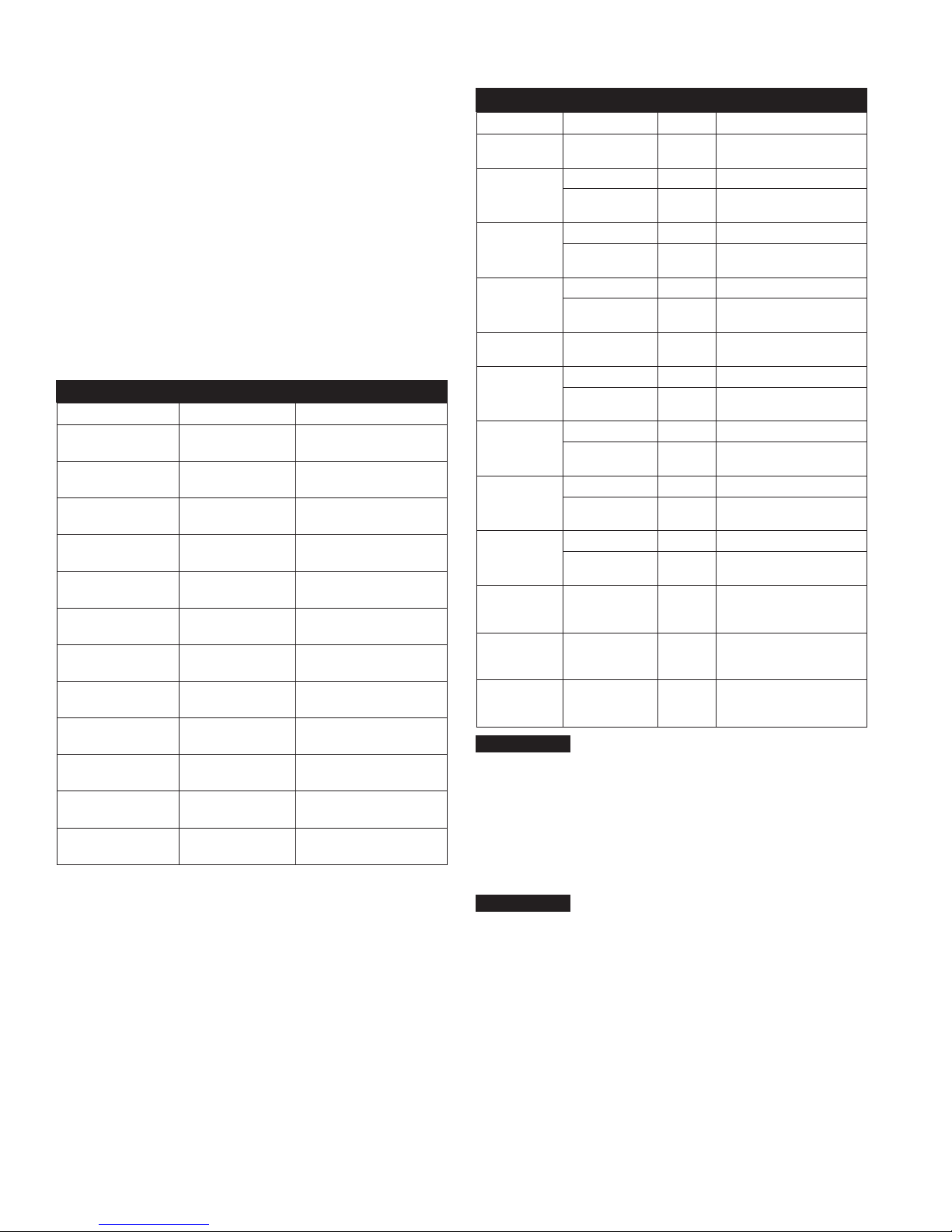
Maximum Flow Rate:
System Model Flow Rate Chlorine Capacity
QTCBMX-1S-1M 1.5 GPM
QTCBMX-2S-1M 1.5 GPM
QTCBMX-3S-1M 3 GPM
QTCBMX-4S-1M 4.5 GPM
QTCBMX-1L-1M 1.5 GPM
QTCBMX-2L-1M 1.5 GPM
QTCBMX-3L-1M 3 GPM
QTCBMX-4L-1M 4.5 GPM
QTCBMX-5L-1M 6 GPM
QTCBMX-1L-.5M 1.5 GPM
QTCBMX-2L-.5M 3 GPM
QTCBMX-3L-.5M 4.5 GPM
QT Cube Max line is available in different congurations depending
upon ltration and ow requirements.
3
⁄8" (10mm) NPT for models
System Flow Rate and Capacity
(5.7 LPM)
(5.7 LPM)
(11.4 LPM)
(17.1 LPM)
(5.7 LPM)
(5.7 LPM)
(11.4 LPM)
(17.1 LPM)
(22.8 LPM)
(5.7 LPM)
(11.4 LPM)
(17.1 LPM)
20,000 Gallons
20,000 Gallons
40,000 Gallons
60,000 Gallons
22,000 Gallons
22,000 Gallons
44,000 Gallons
66,000 Gallons
88,000 Gallons
NA
NA
NA
Replacement Filters
System Replacement Filters
System Model Filter Ordering Code Frequency Description
QTCBMX-1S-1M QTCM15S* 6 Months
HSR-L-SED-5M 6 Months 20" 5 Micron Sediment Pre Filter
QTCBMX-2S-1M
QTCBMX-3S-1M
QTCBMX-4S-1M
QTCBMX-1L-1M QTCM20S* 6 Months
QTCBMX-2L-1M
QTCBMX-3L-1M
QTCBMX-4L-1M
QTCBMX-5L-1M
QTCBMX-1L-.5M
QTCBMX-2L-.5M
QTCBMX-3L-.5M
QTCM15 6 Months
HSR-L-SED-5M 6 Months 20" 5 Micron Sediment Pre Filter
QTCM15 6 Months
HSR-L-SED-5M 6 Months 20" 5 Micron Sediment Pre Filter
QTCM15 6 Months
HSR-L-SED-5M 6 Months 20" 5 Micron Sediment Pre Filter
QTCM20 6 Months
HSR-L-SED-5M 6 Months 20" 5 Micron Sediment Pre Filter
QTCM20 6 Months
HSR-L-SED-5M 6 Months 20" 5 Micron Sediment Pre Filter
QTCM20 6 Months
HSR-L-SED-5M 6 Months 20" 5 Micron Sediment Pre Filter
QTCM20 6 Months
QTCMX20S* 6 Months
QTCMX20 6 Months
QTCMX20 6 Months
NOTICE
Filter cartridges should be changed at end of filter life, due to lack of
filtering performance, or whenever a 15 psi pressure drop or greater
is experienced during normal operation, whichever comes first.
For all replacement filters and components contact your authorized
Hydro-Safe Foodservice representative.
*The QTCM15S, QTCM20S and QTCMX20S are the same filters as the
QTCM15, QTCM20 and QTCMX20 respectively. Only the label position has
been changed so that the label faces forward on single cartridge systems.
NOTICE
Cartridge capacities are estimates and may be less depending on
incoming water quality.
15" QT 0.5 Micron Carbon Block
with Phosphate Scale Control
15" QT 0.5 Micron Carbon Block
with Phosphate Scale Control
15" QT 0.5 Micron Carbon Block
with Phosphate Scale Control (2)
15" QT 0.5 Micron Carbon Block
with Phosphate Scale Control (3)
20" QT 0.5 Micron Carbon Block
with Phosphate Scale Control
20" QT 0.5 Micron Carbon Block
with Phosphate Scale Control
20" QT 0.5 Micron Carbon Block
with Phosphate Scale Control (2)
20" QT 0.5 Micron Carbon Block
with Phosphate Scale Control (3)
20" QT 0.5 Micron Carbon Block
with Phosphate Scale Control (4)
20" QT 0.5 Micron Ultra Filtration
Membrane with Phosphate Scale
Control
20" QT 0.5 Micron Ultra Filtration
Membrane with Phosphate Scale
Control (2)
20" QT 0.5 Micron Ultra Filtration
Membrane with Phosphate Scale
Control (3)
Notice to Installer
• Do not discard this manual after installation. This manual contains
important operation, maintenance and precautionary information.
Please present this manual to the user/owner/operator after
installation.
• It is strongly suggested that you read this manual before installing
system to ensure the best possible installation.
• Installation must comply with all local and state plumbing codes
and regulations.
• Connect the system to cold water supply only. Water Temperature
cannot exceed 100°F (38°C).
2
Page 3

• System must be installed in a vertical, upright and level position.
• Do not use with water that is microbiologically unsafe or of
unknown water quality.
Installation Precautions
• Do not install system on line pressure above the rated pressure as
noted in System Specications above.
• Do not install the system on a hot water line. Failure to limit the
water temperature to 100°F (38°C) can result in housing failure and
property damage.
• Do not connect the system backwards with the feed water line
connected to the outlet.
• Do not use liquid pipe thread compounds for threaded
connections. Use Teon
• Do not solder plumbing connections that are attached to the
housings or inlet/outlet ttings. System damage may occur due to
high temperature.
• Do not allow the system to freeze. Turn off water supply and drain
the system if temperature falls below 32°F (0°C).
• Do not install system in direct sunlight or where the system will be
exposed to harsh chemicals or may be subjected to being hit by
moving equipment, carts, mops, or any other item that may cause
damage.
• Allow 3" (76mm) minimum clearance under the housings for lter
replacement.
• If water hammer is evident, install water hammer arrestors before
the system.
• Do not over tighten tting connections.
• Always back up valves and ttings with a wrench when installing
ttings to avoid over tightening or loosening existing ttings.
• Do not install the unit behind equipment where it may be difcult to
access the system for future lter replacements.
Position the system in a suitable location. The direction of ow
through the system is left to right. Keep this in mind when determining installation locations. Do not mount the system near any source
of heat. Also do not mount this system over anything that may be
adversely affected by water.
®
tape only.
Operation
With sufcient pressure, operation of this system is completely automatic. Dependable operation involves only monitoring system pressure differential, periodic lter changes, and service documentation.
Installation
NOTICE
There is some light eld assembly required for this system.
Before beginning the installation of this system, please make
sure all components are present. Compare the contents of this
box to the system drawings located at the end of this manual.
As illustrated by the drawings, not all systems utilize pressure
gauges. These drawings will be referenced in the installation
instruction steps.
1. Turn off all equipment to be fed by the system, locate the water
supply shutoff valve and turn it off.
2. Apply Teflon tape to the threads of the inlet and outlet valve assemblies
and pressure gauges (if supplied for your model). DO NOT USE PASTE
TYPE THREAD SEALANT. Thread the inlet and outlet valve assemblies
into the inlet and outlet ports of the system as shown on the system
drawings in this manual. Install the pressure gauges, if applicable, into
the gauge ports as indicated by the system drawings in this manual.
NOTICE
DO NOT OVER TIGHTEN THESE FITTINGS INTO THE FILTER HEADS.
When installing fittings onto this system, back any existing receiving fittings
with a wrench to prevent fitting movement. Use a wrench to tighten gauges
into their connection ports. Do not twist on gauge case.
3.
Install the filters into the filter manifold. Make sure all plastic wrapping
and protective plastic caps have been removed from the filters prior to
their installation. Insert the prefilter into its blue canister. Make sure the
blue canister's oring is properly inserted into its oring groove. Thread the
housing onto the head with standard clockwise rotation (when viewed
from below). Hand tighten the blue housing (Not all systems will have
a blue prefilter. See the system drawings in this manual for proper filter
placement). Then install the QT style filter cartridges. To install these
filters, push them into the heads and give them a quarter twist (clockwise
when viewed from below). When the filter is completely inserted, the
cartridge label will be front centered.
4. Anchor the system on a wall stud or suitable mounting material
spanning wall studs. System must be vertical, upright and
level. The mounting hardware used must be selected and
installed so that the system is rmly pressed against the
mounting surface. The system mounting hardware must keep
the system from moving during routine service and operation.
5. Run a suitable line from the tap water source to the inlet ball
valve on the left side of the system. Brace the inlet ball valve on
the system with a wrench when connecting the feed water line.
NOTICE
DO NOT OVERTIGHTEN CONNECTION FITTING INTO
BALL VALVE.
6. Select the appropriate size tubing for the equipment being fed,
and connect it to the outlet ball valve of the system.
NOTICE
DO NOT OVERTIGHTEN CONNECTION FITTING INTO BALL
VALVE.
7. Install the ¼" (8mm) tubing into the Quick-Connect tting on the
outlet of the system and hold it over a drain. Open the
drain valve.
8. Once all inlet and outlet piping has been completed, check and
make sure all lter housing(s) are tight, slowly open the inlet valve
and allow all air to purge from the system through the 1/4"
tubing. Slowly close the
to reach operating pressure, and check for leaks.
9. If no leaks are present, open the
allow it to run to drain for 5 minutes to ush the system. Then
close the valve.
10. Open the outlet water valve and check for leaks.
11. Record the start up date and pressure gauge values in system
maintenance log.
NOTICE
Overtightening components can damage the system causing
water damage and/or system failure.
1
⁄4" (8mm)
1
⁄4" (8mm) drain valve, allow the system
1
⁄4" (8mm) drain line again and
Maintenance
Routine maintenance of this system involves periodic lter changes.
Filter cartridges should be changed at end of lter life, due to lack of
ltering performance, or whenever a 15 psi pressure drop or greater
is experienced during normal operation, whichever comes rst.
Filter Cartridge Replacement Procedure
!
WARNING
Determine whether all equipment connected to the system must
be turned off prior to shutting off water supply from lters.
1. If required, turn off downstream equipment.
2. Turn OFF water to the system by closing the inlet and outlet ball
valves.
3. Open the ¼" drain valve on the outlet of the system to relieve
pressure in the housings.
Remove all filters. The blue prefilter housing unscrews to the left when
4.
viewed from underneath. It has a standard right hand thread. The QT
style filters are removed by rotating them 1/4 turn to the left and then
gently pulling down.
3
Page 4
5. Clean inside of blue housing sump with warm water. If desired,
disinfect housing using a teaspoon of household bleach. Add
to lter bowl and ll with water. Let stand 5 minutes and then
discard and rinse.
6. Insert new QT style lters into the manifold assembly. Push up
and twist each QT cartridge 1/4 turn to the right to properly
install it into the manifold assembly. When making the 1/4 turn,
the cartridge label should come to a stop facing you.
Insert a new prefilter cartridge into the blue prefilter housing. Check
7.
O-ring for damage and replace if damaged or distorted. Make certain
the O-ring is properly positioned and reinstall the filter housing. Tighten
housings hand tight.
Do not overtighten lter housing, overtightening may damage
O-ring(s), cause water leaks, or affect system performance.
8. Slightly open the inlet ball valve and fully open the ¼" drain
valve. Once full ow of water ows from the drain port, slowly
open the inlet valve to the full open position. Allow water to ush
to drain for 5 minutes.
9. Slowly close the drain valve and check the system for leaks.
10. Slowly open the outlet valve to restore water ow to downstream
equipment.
11. Record lter change date in system maintenance log.
Teflon® is a registered trademark of E.I. DuPont de Nemours & Company.
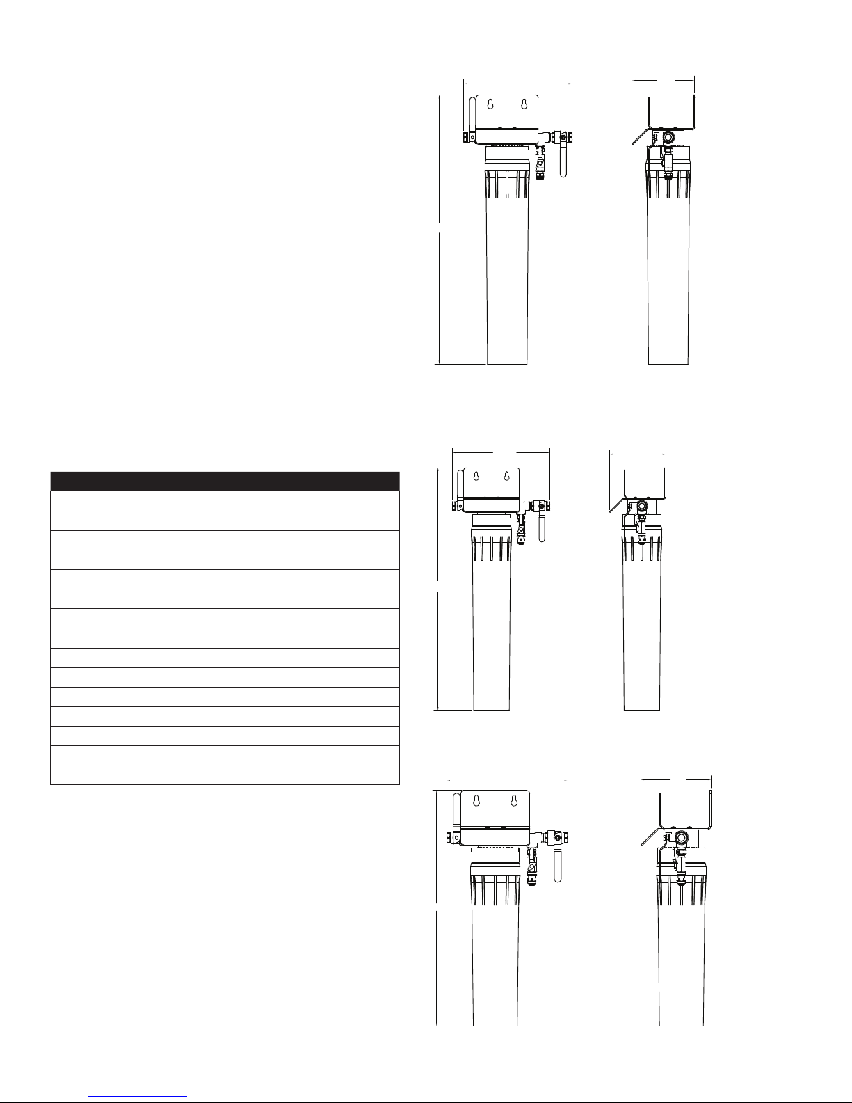
QTCBMX-1L-.5M
10.03
23.87
QTCBMX-1L-1M
5.56
Replacement Parts
Description Ordering Code
Filter Head 3/8" Top In/Out Quick Connect HSR-QTHD-QC38
Filter Head 3/8" Side In/Out FNPT HSR-QTHD-TT38
Manifold Head First Stage With NPT Inlet HSR-QTMHF-NPT
Manifold Head First Stage With Oring Inlet HSR-QTMHF-OR
Manifold Head Middle Stage HSR-QTMHM
Manifold Head Last Stage HSR-QTMHL
Manifold Head Only Stage With Oring Inlet HSR-QTMHS-OR
Ball Valve 3/8 NPT Brass HSR-BV3/8
Ball Valve 1/4 NPT Plastic HSR-BV1/4P
Ball Valve 1/4 NPT Brass HSR-BV1/4LH
Ball Valve 1/2 NPT Brass HSR-BV1/2
Inlet Bottom Mount Pressure Gauge HSR-GAUGE
Outlet Back Mount Pressure Gauge HSR-GAUGE-BKM
20" Slimline Prefilter Housing With Gauge Port HSR-20HSPF-12
Slimline O-Ring HSR-RING-S
10.03
23.87
QTCBMX-1S-1M
10.03
5.56
5.56
18.75
4
Page 5
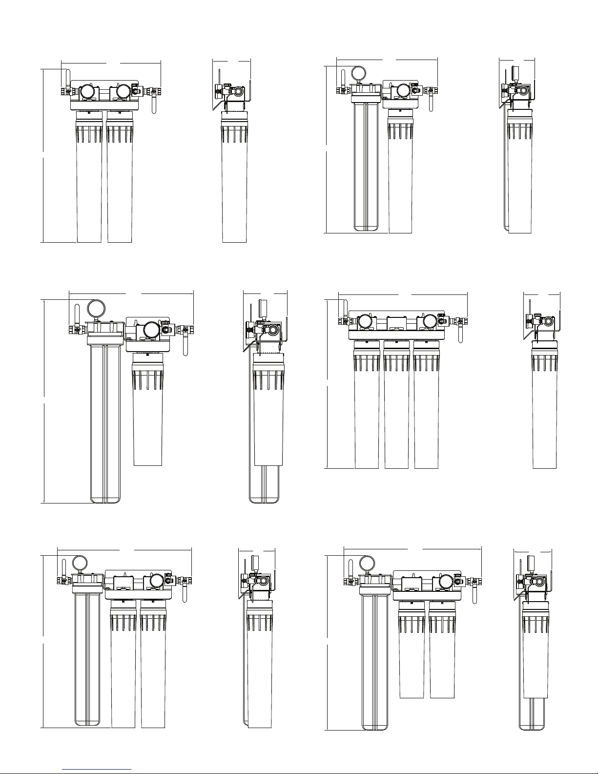
QTCBMX-2L-.5M
QTCBMX-2L-1M
25.51
QTCBMX-2S-1M
14.69
15.73
5.56
5.56
15.73
26.08
QTCBMX-3L-.5M
19.44
5.56
5.56
25.70
26.08
20.30
5.56
25.51
QTCBMX-3S-1M QTCBMX-3L-1M
25.70
20.30
5.56
5
Page 6

QTCBMX-4S-1M QTCBMX-4L-1M
24.73
26.08
QTCBMX-5L-1M
29.23
5.56
5.56
25.70
24.73
5.56
26.08
NOTICE
Allow 3" (76mm) of clearance at bottom of system for removal of filter
bowls for filter cartridge replacement
6
Page 7

Notes
7
Page 8
WARNING: This product contains chemicals known to the
State of California to cause cancer and birth defects or
other reproductive harm.
For more information: www.watts.com/prop65
LIMITED WARRANTY: Watts Regulator Co. (the “Company”) warrants each QT Cube Max water ltration line system, excluding lters and water treatment cartridges, to be free from defects in material and
workmanship under normal usage for a period of ve years from the date of original shipment. The Company warrants all lters and water treatment cartridges to be free from defects in material and
workmanship under normal usage for a period of one year from the date of original shipment. In the event of such defects within the warranty period, the Company will, at its option, replace or recondition
the product without charge.
THE WARRANTY SET FORTH HEREIN IS GIVEN EXPRESSLY AND IS THE ONLY WARRANTY GIVEN BY THE COMPANY WITH RESPECT TO THE PRODUCT. THE COMPANY MAKES NO OTHER WARRANTIES, EXPRESS OR IMPLIED.
THE COMPANY HEREBY SPECIFICALLY DISCLAIMS ALL OTHER WARRANTIES, EXPRESS OR IMPLIED, INCLUDING BUT NOT LIMITED TO THE IMPLIED WARRANTIES OF MERCHANTABILITY AND FITNESS FOR A PARTICULAR PURPOSE.
The remedy described in the first paragraph of this Limited Warranty shall constitute the sole and exclusive remedy for breach of warranty, and the Company shall not be responsible for any incidental, special or consequential
damages, including without limitation, lost profits or the cost of repairing or replacing other property which is damaged if this product does not work properly, other costs resulting from labor charges, delays, vandalism,
negligence, fouling caused by foreign material, damage from adverse water conditions, chemical, or any other circumstances over which the Company has no control. This warranty shall be invalidated by any abuse, misuse,
misapplication, improper installation or improper maintenance or alteration of the product. Some States do not allow limitations on how long an implied warranty lasts, and some States do not allow the exclusion or
limitation of incidental or consequential damages. Therefore the above limitations may not apply to you. This Limited Warranty gives you specific legal rights, and you may have other rights that vary from State to State.
You should consult applicable state laws to determine your rights. SO FAR AS IS CONSISTENT WITH APPLICABLE STATE LAW, ANY IMPLIED WARRANTIES THAT MAY NOT BE DISCLAIMED, INCLUDING THE IMPLIED
WARRANTIES OF MERCHANTABILITY AND FITNESS FOR A PARTICULAR PURPOSE, ARE LIMITED IN DURATION TO ONE YEAR FROM THE DATE OF ORIGINAL SHIPMENT.
A Watts Water Technologies Company
IOM-HS-QTCubeMax 1335 X0FHSQTCMIOM © 2013 Watts
Tel: (800) 264-1183 • Fax: (724) 733-4808 • foodservice.watts.com
 Loading...