

Page 1
For Residential and Commercial Applications
ES-LFU5B
Job Name
Job Location
Engineer
Approval
LEAD FREE
–––––––––––––––––––––––––––––––––––––––––––
–––––––––––––––––––––––––––––––––––––––––
–––––––––––––––––––––––––––––––––––––––––––––
–––––––––––––––––––––––––––––––––––––––––––––
*
Series LFU5B
Water Pressure Reducing Valves**
Sizes: 1⁄2" – 2" (15 – 50mm)
Series LFU5B Water Pressure Reducing Valves are designed to reduce
incoming water pressure to a sensible level to protect plumbing system
components and reduce water consumption. The LFU5B features Lead Free*
construction to comply with Lead Free* installation requirements. This series
is suitable for water supply pressures up to 300psi (20.7 bar) and may be
adjusted from 25 – 75psi (172 – 517 kPa). The standard setting is 50psi
(345 kPa). All parts are quickly and easily serviceable without removing
the valve from the line. The LFU5B’s standard bypass feature permits the
flow of water back through the valve into the main when pressures, due to
thermal expansion on the outlet side of the valve, exceed the pressure in the
main supply.
Features
• Standard construction includes Z3 sealed spring cage and stainless steel
corrosion resistant adjusting cage screws for accessible outdoor
pit installations
or
• Integral stainless steel strainer
• Replaceable seat module
• Lead Free* cast copper silicon alloy body construction
• Serviceable in line
• Bypass feature controls thermal expansion pressure (LFU5B-Z3)***
• High temperature resistant reinforced diaphragm for hot water
Models
LFU5B-Z3 NPT threaded female union inlet x NPT female outlet w/built in
LFU5B-S-Z3 Solder union inlet x NPT female outlet w/built in thermal
LF5M3-Z6 Water meter threaded connections and 7
LFU5B-QC-Z3 Quick-Connect Single-Union – Inlet end
thermal expansion bypass
expansion bypass
length for new or existing meter box installations. For
5
(16mm),
setters or resetters
⁄8" x 3⁄4" (16 x 20mm) or 3⁄4" (20mm) meter
1
⁄2" (190mm) lay
5
⁄8"
Contractor
Approval
––––––––––––––––––––––––––––––––––––––––––––
–––––––––––––––––––––––––––––––––––––––––––––
Contractor’s P.O. No.
Representative
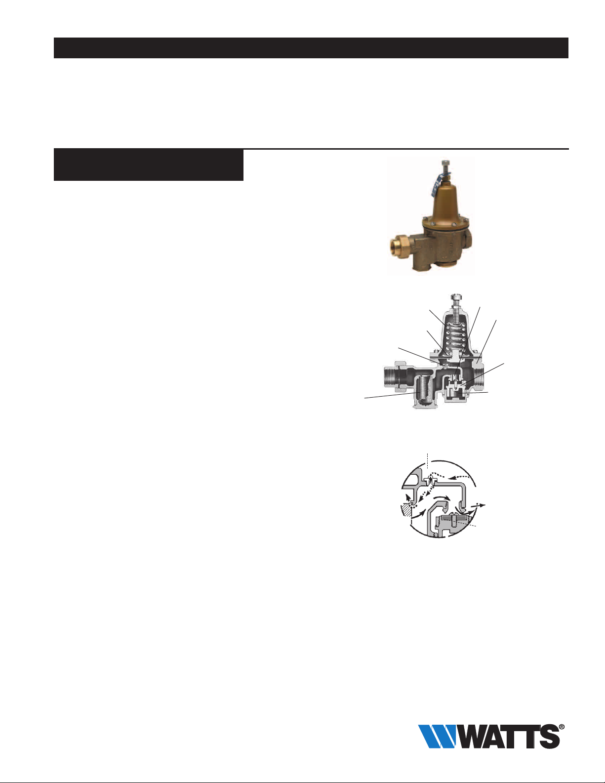
Sensitive spring and large diaphragm
area provide for accurate pressure
control and wide range of adjustment.
High temperature resisting diaphragm for hot or cold water.
Suffix B Bypass feature
Large integral
stainless steel
strainer screen
easily removed
for cleaning.
Thermal Expansion Bypass Check Valve Feature
––––––––––––––––––––––––––––––––––––––––
LFU5B-Z3
Expanded
Pressure
Initial
Pressure
––––––––––––––––––––––––––––––––––
Stainless steel seat
Lead Free* copper
silicon alloy body
construction
Disc holder removable
for replacement of disc
without dismantling
the valve - no special
tools required.
Spring (not shown)
“LP” Model only
Suffix B
Reduced
Pressure
Inlet Seat and Disc
Specifications
Standard Specifications: A Water Pressure Reducing Valve with integral
strainer shall be installed in the water service pipe near its entrance to the
building where supply main pressure exceeds 60psi (413 kPa) to reduce
it to 50psi (345 kPa) or lower. The water pressure reducing valve shall be
constructed using Lead Free* materials. Lead Free* regulators shall comply
with state codes and standards, where applicable, requiring reduced lead
content. The valve shall feature a Lead Free* cast copper silicon alloy body
suitable for water supply pressures up to 300psi (20.7 bar). Provision shall
be made to permit the bypass flow of water back through the valve into the
main when pressures, due to thermal expansion on the outlet side of the
valve, exceed the pressure in the main supply. Water Pressure Reducing
Valve with built-in bypass check valves will be acceptable. Approved valve
shall be listed to ASSE 1003 and IAPMO and certified to CSA B356. Valve
shall be a Watts Series LFU5B-Z3.
Watts product specifications in U.S. customary units and metric are approximate and are provided for reference only. For precise measurements,
please contact Watts Technical Service. Watts reserves the right to change or modify product design, construction, specifications, or materials without prior notice and without incurring any obligation to make such changes and modifications on Watts products previously or subsequently sold.
* The wetted surface of this product contacted by consumable
water contains less than 0.25% of lead by weight.
** A water saving test program concluded that reducing the supply
pressure from 80-50psi (551-345 kPa) resulted in a water savings of
30%.
*** The bypass feature will not prevent the pressure relief valve from
opening on the hot water supply system with pressure above 150psi
(10.3 bar).
Page 2
Materials
Body: Lead Free* cast copper silicon alloy
Seat: Replaceable stainless steel
Integral Strainer: Stainless steel
Diaphragm: Reinforced EPDM
Valve Disc: EPDM
Yoke: Lead Free* cast copper silicon alloy
LF5M3-Z6 model provided with cast iron spring cage
Pressure – Temperature
Temperature Range: 33°F – 160°F (0.5°C – 71°C)
Maximum Working Pressure: 300psi (20.7 bar)
Adjustable Reduced Pressure Range: 25 – 75psi (172 – 517 kPa)
Standard Reduced Pressure Setting: 50psi (345 kPa)
Options
Add Suffix
G Gauge tapping
GG Gauge tapping and 160psi (11.0 bar) gauge
HP High pressure range 75 – 100psi (5.2 – 6.9 bar)
LP Low pressure range 10 – 35psi (69 – 241 kPa)
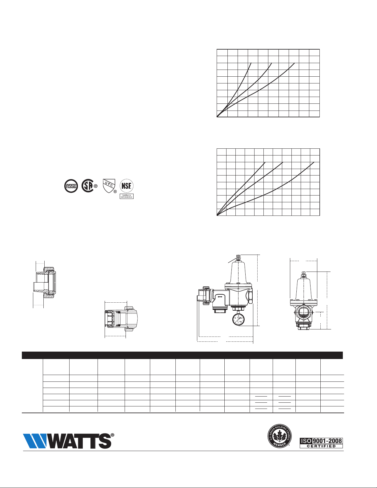
Capacity
kPa psi
172 25
138 20
103 15
69 10
34 5
0 0
Reduced Pressure Fall-off
kPa psi
172 25
138 20
103 15
Sizes 1⁄2", 3⁄4", 1" (15, 20, 25mm)
0 10 20 30 40 50 gpm
0 38 76 114 152 190 lpm
Sizes 11⁄4", 11⁄2", 2" (32, 40, 50mm)
1
⁄2"
11⁄4"
3
⁄4"
11⁄2"
1"
2"
Standards
Meets requirements of ASSE Standard 1003; (ANSI A112.26.2); CSA
69 10
34 5
Standard B356; Southern Standard Plumbing Code and listed by IAPMO.
0 0
Reduced Pressure Fall-off
10 30 50 70 90 110 gpm
38 114 190 266 342 418 lpm
Dimensions - Weights
Et
Es
MODEL SIZE (DN) DIMENSIONS WEIGHT
A A1 C D G Et Es EQC FQC F
in. mm in. mm in. mm in. mm in. mm in. mm in. mm in. mm in. mm in. mm in. mm lbs. kgs.
LFU5B-Z3 1⁄2 15 55⁄8 142.8 51⁄2 139.7 57⁄8 149.2 15⁄8 41.2 31⁄16 77.7 7⁄16 11.1 1⁄2 12.7 17⁄16 36 11⁄2 38 101⁄4 260.3 4 1.8
=
Dimension includes optional gauge
3
⁄4 20 63⁄16 157.1 61⁄4 158.7 67⁄8 174.6 17⁄8 47.6 31⁄2 88.9 1⁄2 12.7 3⁄4 19 19⁄16 40 111⁄16 42 111⁄2 292.1 5 2.3
1 25 65⁄8 168.2 63⁄4 171.4 73⁄8 187.3 2 50.8 4 101.6 9⁄16 14.2 7⁄8 22.2 111⁄16 43 13⁄4 45 121⁄8 307.9 6 2.7
11⁄4 32 715⁄16 190.5 711⁄16 195.2 83⁄8 212.7 21⁄4 57.1 41⁄2 113.3 5⁄8 15.8 1 25.4 133⁄8 339.7 9.4 4.3
11⁄2 40 97⁄16 239.7 93⁄4 247.6 93⁄8 238.1 27⁄8 73 43⁄4 120.6 5⁄8 15.8 11⁄8 28.5 15 381.0 14.4 6.5
2 50 107⁄8 276.2 111⁄2 292.1 121⁄4 311.1 31⁄4 82.5 6 152.4 5⁄8 15.8 13⁄8 34.9 181⁄4 463.5 23 10.4
A - LFU5B-Z3
A1 - LFU5B-S-Z3
ET - NPT Engagement for tight joint
ES - Female sweat socket depth
EQC - Quick-Connect
FQC
EQC
G
F* (Max)
C (Max)
D
A
A1
=
A Watts Water Technologies Company
ES-LFU5B 1323 © 2013 Watts
USA: Tel: (978) 688-1811 • Fax: (978) 794-1848 • www.watts.com
Canada: Tel: (905) 332-4090 • Fax: (905) 332-7068 • www.watts.ca
 Loading...