

Page 1
Installation, Maintenance, & Repair
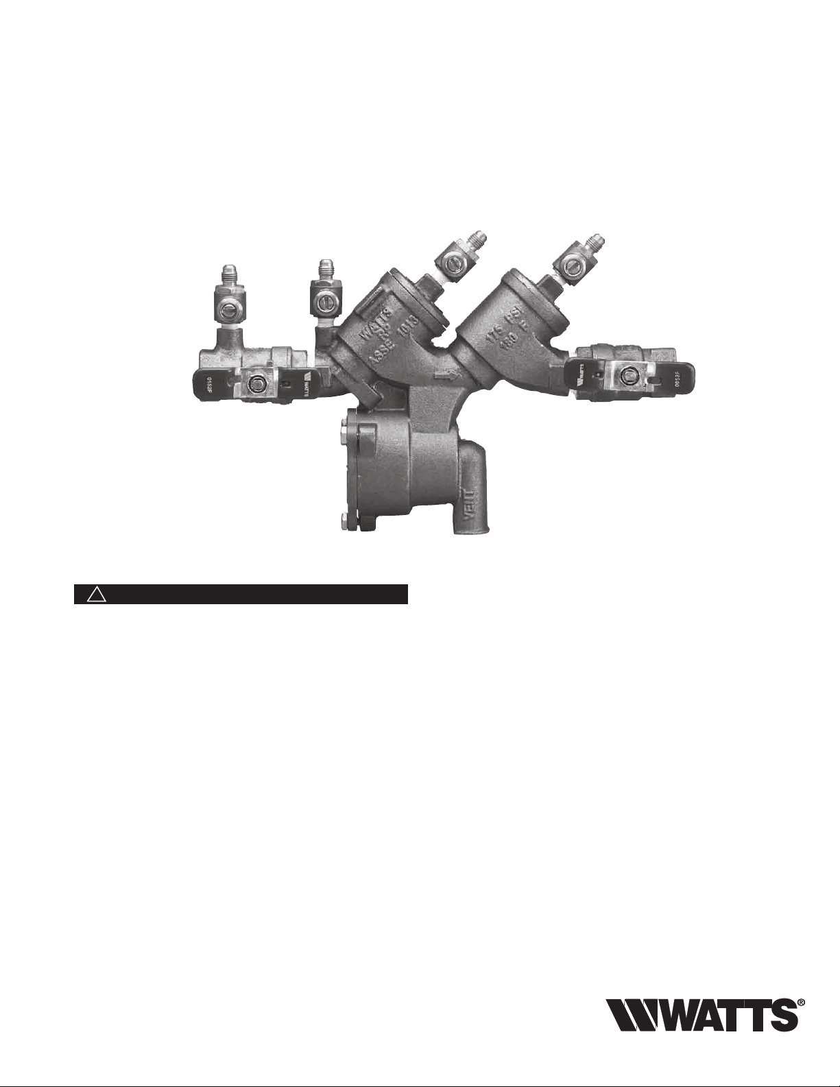
Series 919 and LF919
Reduced Pressure Zone Assemblies
Sizes: 1⁄4" – 2" (8 – 50mm)
RP/IS-919
919QT
WARNING
!
You are required to thoroughly read all installation instructions
and product safety information before beginning the installation of this product. FAILURE TO COMPLY WITH PROPER
INSTALLATION AND MAINTENANCE INSTRUCTIONS
COULD RESULT IN PRODUCT FAILURE WHICH CAN
CAUSE PROPERTY DAMAGE, PERSONAL INJURY AND/
OR DEATH. Watts is not responsible for damages resulting
from improper installation and/or maintenance.
Local building or plumbing codes may require modifications to
the information provided. You are required to consult the local
building and plumbing codes prior to installation. If this information is not consistent with local building or plumbing codes, the
local codes should be followed.
Need for Periodic Inspection/Maintenance: This product
must be tested periodically in compliance with local codes, but
at least once per year or more as service conditions warrant.
Corrosive water conditions, and/or unauthorized adjustments
or repair could render the product ineffective for the service intended. Regular checking and cleaning of the product’s internal
components helps assure maximum life and proper product
function.
NOTE: For Australia and New Zealand, line strainers should be
installed between the upstream shutoff valve and the inlet of the
backflow preventer.
Its important that this assembly be tested periodically in compliance with local codes, but at least once per year or more as
service conditions warrant. If installed on a fire sprinkler system, all
mechanical checks, such as alarm checks and backflow preventers, should be flow tested and inspected internally in accordance
with NFPA 13 and NFPA 25.
Testing
For field testing procedure, send for IS-TK-DL, IS-TK-7,
IS-TK-9A, IS-TK-99E AND IS-TK-99D.
For other repair kits and service parts, send for PL-RP-BPD.
For technical assistance, contact your local Watts
representative.
Page 2
Installation Instructions
Series 919 and LF919
1
⁄4" – 2" (8 – 50mm)
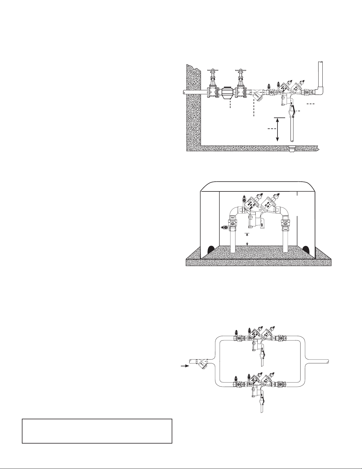
Indoor Installation
Reduced Pressure Zone Assemblies
Indoor Installation
For indoor installations, make sure the Series 919 and LF919 is
easily accessible to facilitate testing and servicing. Do not install in
concealed locations. If the location of the Series 919 and LF919
is parallel and close to the wall, make sure the test cocks are easily accessible, and the drain line can adequately drain if required.
An air gap and drain line (see literature ES-AG/EL/TC) are piped
from the relief valve connection as shown, allowing evidence of
discharge to be clearly visible and preventing the occurrence of
water damage.
Outdoor, Above Ground Installation
For outdoor installations, it is recommended that you install the
Series 919 and LF919 where there are no freezing conditions and
above ground whenever possible.
You must install the Series 919 and LF919 in an accessible location to facilitate testing and servicing. The installation must also
allow for adequate drainage from the air gap and the discharge
line if needed.
WARNING:
1. Do not allow the drain line to empty directly into a drainage
ditch, sewer system, or sump.
2. Do not install the Series 919 and LF919 in any location where
any part of the unit could become submerged in standing
water.
Watts
1
⁄4" – 2" (8 – 50mm) 919
Meter
Strainer
12" (300mm) Minimum
(refer to local codes)
Outdoor Installation
FIBERGLASS WattsBox
1
(8 – 50mm)
919AQT
Min. 12" (300mm)
Min. 12"
Now available, Wa ttsBox Insulated Enclosures,
for more information, send for literature ES-WB.
Air Gap
Watts
⁄4" – 2"
Parallel Installation
For parallel installations, you can install two or more small sized
Series 919's and LF919's (when approved) to serve a large supply
pipe main. You can use this type of installation in an application
where increased capacity beyond that provided by a single valve
is required. Additionally, this type of installation permits testing
and/or servicing of a single valve without shutting down the complete line.
The number of Series 919 and LF919 units installed in parallel
should be determined by the engineer's judgement, based on the
operating conditions of a specific application.
NOTE: The total capacity of all the units installed in the application
should equal or exceed that required by the system.
Annual inspection of all water system safety and control valves
is required and necessary. Regular inspection, testing and
cleaning assures maximum life and proper product function.
2
Parallel Installation
Watts
1
⁄4" – 2" 919
(8 – 50mm)
Page 3
Installation Instructions
1/2"
3/4" M2
1" M2
Series 919 and LF919
1
⁄4" – 2" (8 – 50mm)
A. Shutoff Valves: If you remove the shutoff valves from the Series 919 and LF919, reassemble
the shutoff valve with the test cock mounted on the inlet side of the unit.
B. Always install the Series 919 and LF919 in an accessible location to facilitate testing and
servicing (See Page 2). *Check the state and local codes to ensure that you install
the backflow preventer in compliance with those codes, such as the proper height
above the ground.
C. It is recommended that you install a strainer ahead of the Series 919 assemblies to protect
the internal components from unnecessary fouling.
CAUTION:
Do not install a Series 919 and LF919 with a strainer in rarely used water lines, such as a fire
sprinkler system which is only used during emergencies.
Start Up: Close the downstream shutoff. Open the upstream slowly and fill the valve. When the
valve is filled, open the downstream shutoff slowly, and fill the water supply system. This is necessary to avoid water hammer and/or shock damage.
D. Vent the air gap and drain line from the relief valve in accordance with code requirements.
Terminate discharge approximately 12" (300mm) above the ground or through an air gap
piped to a floor drain.
WARNING:
Do not allow the drain line to empty directly into a drainage ditch, sewer system, or sump.
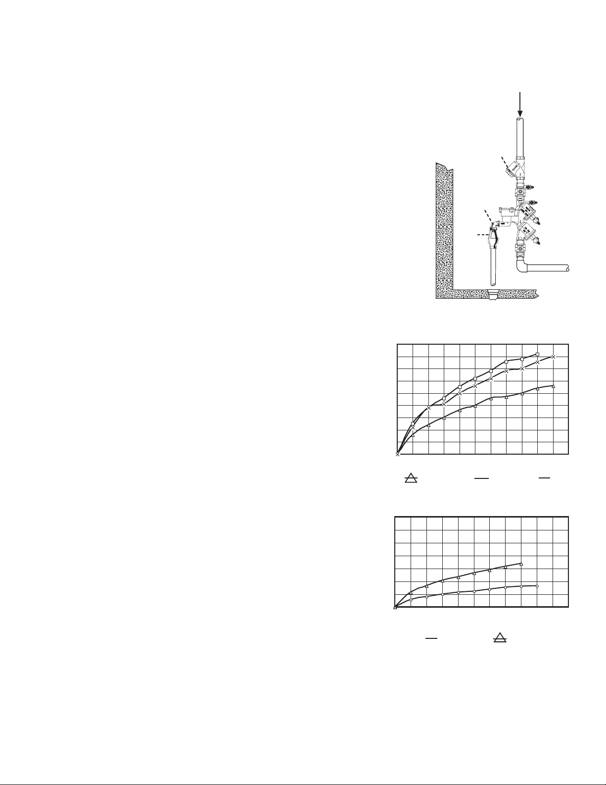
NOTE: Relief Valve Discharge Rates
The Series 919 and LF919 air gap and drain line terminating above a floor drain
can accommodate any moderate discharge or nuisance spitting through the
relief valve. However, to prevent water damage in the case of a catastrophic failure, you may need to design the floor drain size to accommodate the increased
discharge. Refer to Figure 1 for maximum relief valve discharge rates, size, and
capacity of typical floor drains.
NOTE: DO NOT reduce the size of the drain line from the air gap fitting. The drain
line must remain at full line size.
E. After initial installation of the Series 919 and LF919, a discharge from the relief
valve may occur due to dirt and pipe compounds. This may be due to inadequate initial flushing of the pipe lines. If flushing the valve does not clear the
unit, remove the first check valve and clean thoroughly, using the procedures
in "Servicing First & Second Check Valves" on page 6.
NOTE: Periodic relief valve discharge may occur on dead end service applications,
such as boiler feed lines or cooling tower makeup lines. This may be due to fluctuating
supply pressure during a static or no flow condition. To avoid this discharge, install a
spring-loaded, rubber seated check valve ahead of the backflow assembly.
F. It is recommended that you not place the Series 919 and LF919 in a pit or at
a depth below the ground level, unless absolutely necessary. If an installation
requires below ground level installation, a modified pit installation is recommended, as well as the approval of local codes. In such cases, provision
should be made to always vent the drain line above the flood level. In the
case of a pit drain, ensure an adequate air gap exists between the bottom of
the drain line and the bottom of the pit.
G. It is recommended that periodic inspection of the Series 919 and LF919 be
done to check for any discharge from the relief valve. This discharge is a
visual indication that the valve needs cleaning or repair. In addition, it is recommended that periodic testing of the valve be done in compliance with local
codes to ensure its proper operation.
The relief vent discharges water during no-flow periods when:
(1) the first check valve is fouled; or
(2) the inlet pressure to the check valve drops sufficiently due to upstream pres-
sure fluctuations. This affects the required operating differential between the
inlet pressure and the reduced pressure zone; or
(3) the second check is fouled during emergency backflow or resulting from a
water hammer condition.
For troubleshooting guide send for literature S-TSG.
NOTE: When installing the Series 919 and LF919 on fire prevention systems,
special considerations are required.
Fire Protection System Installations: The National Fire Protection Agency (NFPA)
Guidelines require a confirming flow test be conducted by a certified tester whenever a “main line” valve is installed, such as a shutoff valve or a backflow preventer.
45
40
35
30
25
20
15
Flow Rate gpm
10
5
0
0 10 20 30 40 50 60 70 80 90 100 110
(8 – 15mm) (20mm) (25mm)
350
300
250
200
150
100
Flow Rate gpm
50
0
0 10 20 30 40 50 60 70 80 90 100 110
Typical Flow Rates as sized by floor drain manufacturers:
2" 55 GPM 5" 350 GPM
3" 112 GPM 6" 450 GPM
4" 170 GPM 8" 760 GPM
Figure 1
1
⁄4" – 2" 919
Watts
*Vertical Flow Down
Strainer
Elbow
Air
Gap
Floor Drain
1
⁄4" – 1" (8 – 25mm) 919 and LF919
1
⁄4"–1⁄2" c 3⁄4" X 1"
1
1
Zone Pressure psi
⁄4" – 2" (32 – 50mm) 919 and LF919
Zone Pressure psi
0 11⁄4"–11⁄2" 2"
(32 – 40mm) (50mm)
3
Page 4

Servicing the Relief Valve
Series 919 and LF919
1
⁄4" – 2" (8 – 50mm)
NOTES: 1. No special tools are required to service the Series 919 and LF919
2. Before servicing, make sure the water is turned off or shutoff valves are closed.
The following procedures provide information for replacing the diaphragm, the relief valve disc, and the relief valve seat.
It is recommended that you visually inspect these parts to determine if a replacement or cleaning is required.
1
⁄4" - 2".
Disassembling the Relief Valve
1. Remove the relief valve cover bolts while holding the cover down.
2. Turn the cover counterclockwise for
while still applying pressure to the cover with your hand.
WARNING:
Make sure you apply pressure to the cover as you lift it straight off. Due to the release
of pressure when removing the cover, the relief valve spring may eject quickly.
3. Remove the relief valve assembly (includes cover O-ring, stem and diaphragm assembly).
4. Remove the relief valve spring.
5. Remove the pressed in relief valve seat and seat O-ring.
1
⁄4 turn, and lift it straight off
Replacing the Diaphragm
6. Using a wrench, loosen the diaphragm assembly by turning
the hex bolt counterclockwise.
7. Remove the diaphragm and replace with a new diaphragm
if required, or clean the existing diaphragm.The molded step
of the diaphragm should point down towards the relief valve stem.
8. Using a wrench, reassemble the diaphragm assembly
by turning the hex bolt clockwise to tighten.
Relief Valve Seat
Relief
Valve
Spring
Body
Replacing the Relief Valve Disc and Seat
9. Using a phillips screwdriver, remove the screw in the relief valve
disc and replace the disc if required, or clean the existing disc.
10. Place the screw back into the relief valve disc and tighten.
11. Replace the relief valve seat with a new seat if required, or
clean the existing seat.
Reassembling the Relief Valve
12. Place the relief valve seat back into the chamber bore.
13. Slide the diaphragm assembly into the relief valve seat.
14. Place the spring on to the diaphragm assembly.
15. Place the cover O-ring on the diaphragm assembly.
16. Line up the grooves on the relief valve cover with the grooves in the
relief valve body, and turn the cover clockwise
17. Using a wrench, place the bolts back into the cover and tighten.
CAUTION:
If the cover does not lie flat against the relief valve body, the diaphragm assembly is not installed properly and damage can
result. Remove the bolts and cover, realign the diaphragm assembly, and place the cover back on the relief valve body.
18. Open the shutoff valves.
1
⁄4 turn to seat the cover.
Cover
Bolts
Relief
Valve
Cover
Relief Valve Seat O-ring
Relief Valve Disc
Relief Valve Stem
Relief Valve Diaphragm
Diaphragm Nut
Relief Valve Cover O-ring
Quad-Ring
Relief Valve
Disc Screw
4
Page 5

Servicing the Relief Valve
Series 919 and LF919
1
⁄4" – 2" (8 – 50mm)
Relief Valve Seat
Relief
Valve
Spring
Body
Relief
Relief Valve Seat O-ring
Valve
Cover
Cover
Bolts
Relief Valve Cover O-ring
Quad-Ring
Repair Kits
1
⁄4" – 2" (8 – 50mm)
When ordering, specify Ordering Code Number, Kit Number and Valve Size.
ORDERING CODE KIT NO. SIZE
in. mm
Total Repair Kits:
*
0888167 RK 919-T
1
⁄4 – 1⁄2 8 – 15
0888168 RK 919-T 3⁄4 20
0888169 RK 919-T 1 25
0888170 RK 919-T 11⁄4 – 11⁄2 32 – 40
0888171 RK 919-T 2 50
LEAD FREE
Kit consists of: Relief Valve Repair Kit, First Check Repair Kit, Second Check Repair Kit
Total Relief Valve Kits:
*
0888130 RK 919 VT
1
⁄4 – 1⁄2 8 – 15
0888131 RK 919 VT 3⁄4 – 1 20 – 25
0888132 RK 919 VT 11⁄4 – 2 32 – 50
LEAD FREE
Kit consists of: Relief Valve Assembly, RV Spring, and RV Cover O-ring
Relief Valve Rubber Parts Kits:
*
0888135 RK 919 RV
0888136 RK 919 RV
0888137 RK 919 RV 11⁄4 – 2 32 – 50
LEAD FREE
1
⁄4 – 1⁄2 8 – 15
3
⁄4 – 1 20 – 25
Kit consists of: Relief Valve Disc, RV Diaphragm, RV Seat O-ring and Cover O-ring
ORDERING CODE KIT NO. SIZE
in. mm
Relief Valve Seat Kits:
*
0888150 RK 919 SV
0888151 RK 919 SV 3⁄4 – 1 20 – 25
0888153 RK 919 SV 11⁄4 – 2 32 – 50
LEAD FREE
Kit consists of: Relief Valve Seat, RV Seat O-ring and RV Cover O-ring
Relief Valve Cover Kits:
0888155 RK 919 VC
0888156 RK 919 VC
0888158 RK 919 VC 11⁄4 – 2 32 – 50
*
0794142 LFRK 919 VC
LEAD
FREE
0794143 LFRK 919 VC 11⁄4 – 2 32 – 50
Kit consists of: Relief Valve Cover and Cover O-ring
Air Gaps
0881575 919 AGA
0881576 919 AGC
0881577 919 AGF 11⁄4 – 2 32 – 50
Relief Valve Disc
Relief Valve Stem
Relief Valve Diaphragm
Diaphragm Nut
Relief Valve
Disc Screw
1
⁄4 – 1⁄2 8 – 15
1
⁄4 – 1⁄2 8 – 15
3
⁄4 – 1 20 – 25
3
⁄4 – 1 20 – 25
1
⁄4 – 1⁄2 8 – 15
3
⁄4 – 1 20 – 25
*The wetted surface of this product contacted by consumable
water contains less than 0.25% of lead by weight.
5
Page 6

Servicing First & Second Check Valves
Series 919 and LF919
1
⁄4" – 2" (8 – 50mm)
NOTES: 1. No special tools are required to service the Series 919 and LF919
2. Before servicing, make sure the water is turned off or
1. Close shutoff valves up and downstream of the valve.
2. Using an appropriate sized wrench, loosen the check valve
cover. Unscrew the check valve cover and lift it off.
3. Remove the spring.
4. Lift out the disc holder assembly from the body of the valve.
5. To reverse the seat disc, unscrew the disc screw and disassemble
the disc washer and disc rubber from the disc holder assembly.
Reverse the disc rubber so the opposite face is showing.
6. Assemble the disc screw through the disc washer and
disc rubber, and screw it into the disc holder.
7. To replace the seat module, pull the seat module
out of the body by gripping at the reinforcement
ring. Replace the seat module with the new seat
by placing it into the body seat bore.
NOTE: When you tighten the cover in Step 12, the
cover will engage the seat module properly.
8. Insert the disc holder assembly back into the seat module.
9. Replace the spring ensuring that it seats properly on the
disc holder.
WARNING:
The first check valve has a heavy weight spring. The second check valve
has a lighter weight spring. When reassembling the check valves, make
sure you install the correct spring into the correct check valve.
10. Place the cover onto the spring with the internal guide on the cover
positioned inside the end coil.
11. Screw the cover onto the valve body.
12. Tighten the cover using the appropriate sized wrench.
13. Service the second check valve using Steps 2 through 12.
14. Slowly open shutoff valves.
1
⁄4" - 2" (8 – 50mm).
shutoff valves are closed.
Check Seat
Check Seat
O-ring
Check Disc Holder
Check Disc Rubber
Check Disc Washer
Check Disc Screw
Check Assembly
Cover
Cover O-ring
Check Spring
6
Page 7

Servicing First & Second Check Valves
Series 919 and LF919
1
⁄4" – 2" (8 – 50mm)
Check Disc Holder
Check Disc Rubber
Check Disc Washer
Check Disc Screw
Check Seat
Check Seat
O-ring
Check Valve Kits
1
⁄4" – 2" (8 – 50mm)
When ordering, specify Ordering Code Number, Kit Number and
Valve Size.
ORDERING CODE KIT NO. SIZE
in. mm
1st Check Kits:
*
0888110 RK 919 CK1
0888111 RK 919 CK1 3⁄4 20
0888112 RK 919 CK1 1 25
0888113 RK 919 CK1 11⁄4 – 11⁄2 32 – 40
0888114 RK 919 CK1 2 50
LEAD FREE
Kit consists of: Check Assembly, Spring and Cover O-ring
2nd Check Kits:
*
0888115 RK 919 CK2
0888116 RK 919 CK2 3⁄4 20
0888117 RK 919 CK2 1 25
0888118 RK 919 CK2 11⁄4 – 11⁄2 32 – 40
LEAD FREE
0888119 RK 919 CK2 2 50
Kit consists of: Check Assembly, Spring and Cover O-ring
1st or 2nd Check Rubber Parts Kits:
*
0888120 RK 919 RC4
0888121 RK 919 RC4 3⁄4 20
0888122 RK 919 RC4 1 25
0888123 RK 919 RC4 11⁄4 –11⁄2 32 – 40
0888124 RK 919 RC4 2 50
LEAD FREE
Kit consists of: Disc, Seat O-ring and Cover O-ring
*The wetted surface of this product contacted by consumable
water contains less than 0.25% of lead by weight.
1
⁄4 – 1⁄2 8 – 15
1
⁄4 – 1⁄2 8 – 15
1
⁄4 – 1⁄2 8 – 15
Check Assembly
Cover
Cover O-ring
Check Spring
ORDERING CODE KIT NO. SIZE
in. mm
Check Seat Kits:
*
0888125 RK 919 S
1
⁄4 – 1⁄2 8 – 15
0888126 RK 919 S 3⁄4 20
0888127 RK 919 S 1 25
0888128 RK 919 S 11⁄4 – 11⁄2 32 – 40
LEAD FREE
0888129 RK 919 S 2 50
Kit consists of: Seat, Seat O-ring and Cover O-ring
Complete Valve Rubber Parts Kits:
*
0888140 RK 919 RT
1
⁄4 – 1⁄2 8 – 15
0888141 RK 919 RT 3⁄4 20
0888142 RK 919 RT 1 25
0888143 RK 919 RT 11⁄4 – 11⁄2 32 – 40
0888144 RK 919 RT 2 50
LEAD FREE
Kit consists of: 2 Check Discs, 2 Check Seat O-rings, 1 RV Disc
Check Cover Kits:
0888145 RK 919 C
0888146 RK 919 C 3⁄4 20
0888147 RK 919 C 1 25
0888148 RK 919 C 11⁄4 – 11⁄2 32 – 40
0888149 RK 919 C 2 50
*
0794144 LFRK 919 C
0794145 LFRK 919 C 3⁄4 20
0794146 LFRK 919 C 1 25
0794147 LFRK 919 C 11⁄4 – 11⁄2 32 – 40
0794148 LFRK 919 C 2 50
LEAD FREE
Kit consists of: Cover and Cover O-ring
Note: For 1/2" and 3/4" 919R10 models use 1" repair kits.
1
⁄4 – 1⁄2 8 – 15
1
⁄4 – 1⁄2 8 – 15
7
Page 8

Troubleshooting Guide
Series 919 and LF919
Symptom Cause Solution
1. Check valve fails to hold a. Debris on check disc Disassemble and clean
1.0 PSID minimum sealing surface
b. Leaking gate valve Disassemble and clean or repair
c. Damaged seat disc or Disassemble and replace
seat o-ring
d. Damaged guide holding Disassemble clean or replace
check open
e. Weak or broken spring Disassemble and replace spring
2. Chatter during flow a. Worn, damaged or Disassemble and repair or
conditions defective guide replace guide
3. Low flows passing a. Mainline check fouled Disassemble and clean
through mainline
valve b. Meter strainer plugged Disassemble and clean
c. Damaged mainline seat Disassemble and replace
disc or seat
d. Broken mainline spring Disassemble and replace
For additional cross-connection control information, send for F-50 brochure.
Limited Warranty: Watts Regulator Co. (the “Company”) warrants each product to be free from defects in material and workmanship under normal usage for a period of one year from the date of
original shipment. In the event of such defects within the warranty period, the Company will, at its option, replace or recondition the product without charge.
THE WARRANTY SET FORTH HEREIN IS GIVEN EXPRESSLY AND IS THE ONLY WARRANTY GIVEN BY THE COMPANY WITH RESPECT TO THE PRODUCT. THE COMPANY MAKES NO OTHER
WARRANTIES, EXPRESS OR IMPLIED. THE COMPANY HEREBY SPECIFICALLY DISCLAIMS ALL OTHER WARRANTIES, EXPRESS OR IMPLIED, INCLUDING BUT NOT LIMITED TO THE IMPLIED
WARRANTIES OF MERCHANTABILITY AND FITNESS FOR A PARTICULAR PURPOSE.
The remedy described in the first paragraph of this warranty shall constitute the sole and exclusive remedy for breach of warranty, and the Company shall not be responsible for any incidental, special
or consequential damages, including without limitation, lost profits or the cost of repairing or replacing other property which is damaged if this product does not work properly, other costs resulting
from labor charges, delays, vandalism, negligence, fouling caused by foreign material, damage from adverse water conditions, chemical, or any other circumstances over which the Company has no
control. This warranty shall be invalidated by any abuse, misuse, misapplication, improper installation or improper maintenance or alteration of the product.
Some States do not allow limitations on how long an implied warranty lasts, and some States do not allow the exclusion or limitation of incidental or consequential damages. Therefore the above
limitations may not apply to you. This Limited Warranty gives you specific legal rights, and you may have other rights that vary from State to State. You should consult applicable state laws to
determine your rights. SO FAR AS IS CONSISTENT WITH APPLICABLE STATE LAW, ANY IMPLIED WARRANTIES THAT MAY NOT BE DISCLAIMED, INCLUDING THE IMPLIED WARRANTIES OF
MERCHANTABILITY AND FITNESS FOR A PARTICULAR PURPOSE, ARE LIMITED IN DURATION TO ONE YEAR FROM THE DATE OF ORIGINAL SHIPMENT.
A Watts Water Technologies Company
RP/IS-919 1145 EDP# 1915346 © 2012 Watts
USA: Tel: (978) 688-1811 • Fax: (978) 794-1848 • www.watts.com
Canada: Tel: (905) 332-4090 • Fax: (905) 332-7068 • www.wattscanada.ca
 Loading...