

Page 1
Installation Instructions
Residential Reverse Osmosis System
Model FMRO5-MT-AG
Page 2

Installation Instructions
Residential Reverse Osmosis
Drinking Water System
Your Reverse Osmosis System has been tested to
ensure it will operate correctly. The following
periodic maintenance is recommended so your
system will provide years of trouble-free service:
Replacement parts Replacement
Pre-filter (sediment) Every 6 mos.
Pre-filters (activated carbon) Every 6 mos.
R/O membrane Every 2-3 years
Post filter (carbon) Every 6 mos.
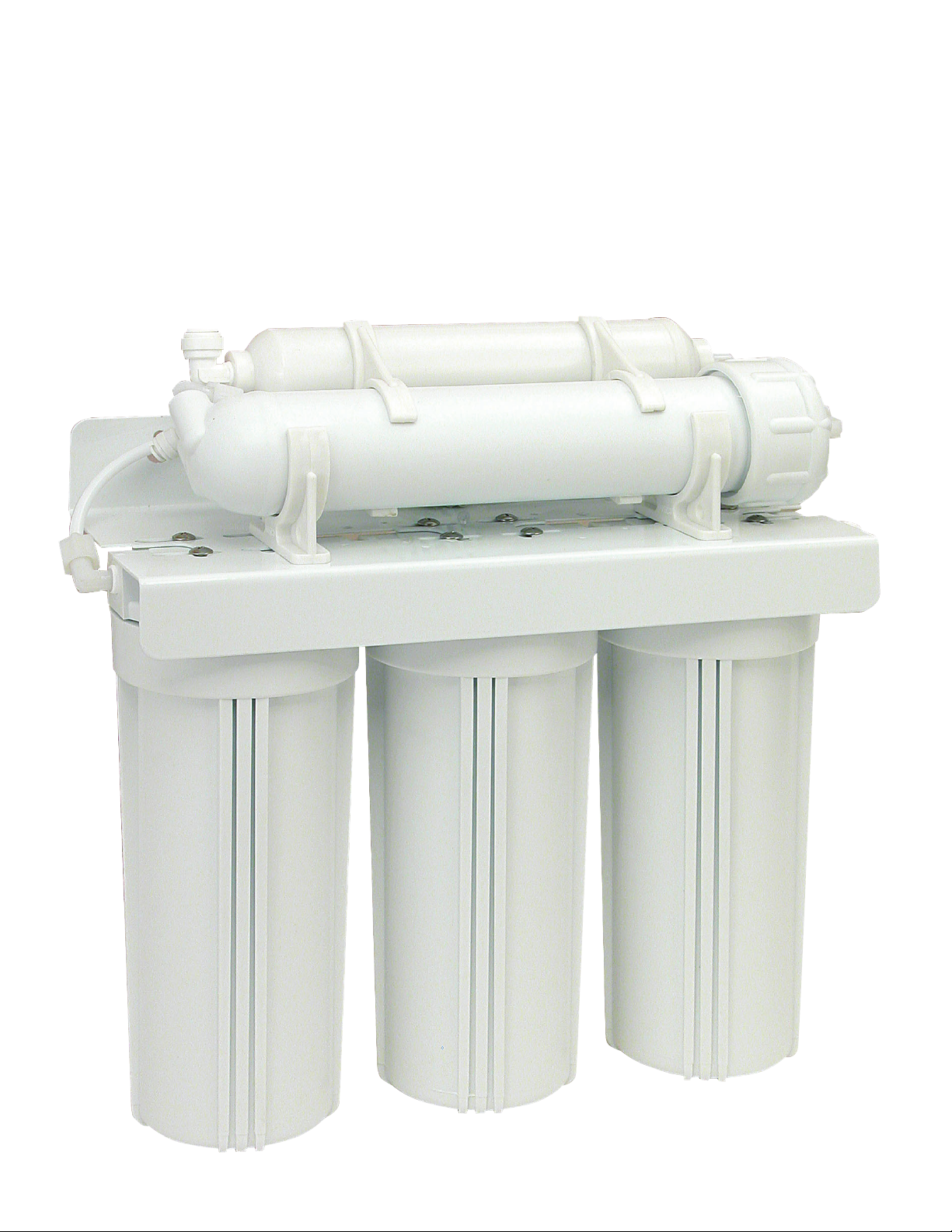
Components
Thefollowing components make up your Reverse
Osmosis DrinkingWaterSystem:
Pre-filter (sediment) removes larger particles such
as sand, silt, rust and scale.
Pre-filters (activated carbon) remove chlorine in the
feed water to protect the reverse osmosis
membrane.
Reverse Osmosis Membrane reduces dissolved
minerals, metals and salts. During the process,
harmful compounds are separated by the
membrane and the reject water goes to waste
(drain).
Filter housings and R/O module hold pre-filters
and membranes. A bracket is provided so they
maybemounted, typically below sink.
Storage tank holds filtered water, ready for use.
Automatic shut-off valve senses when the
storage tank is full and closes the water supply to
conserve water.
The dedicated faucet is used to dispense RO
produced water when needed.
Feed water saddle valve is connected to the cold
water line to supply water to the R/O system.
Waste water saddle valve is connected to the
drain to remove reject water from the R/O system.
Tubing supplies feed and reject water.
Fittings are used for necessary hose connections.
Tools
The following tools may be necessary, depending
on each particular installation:
Center punch and hammer
Concrete drill bits
Phillips head and flat blade screwdrivers
Adjustable wrench
Crescent wrench
Teflon tape
Plastic tube cutter
Air pressure gauge (low pressure)
Air pump (hand)
System location
Your R/O system may be installed under a sink, in a
basement or other location, depending on available
space. Do not install unit where temperatures fall
below freezing; otherwise, damage will result.
Connection to an icemaker should also be
considered for optimum performance.
Guidelines for component placement are as follows:
Faucet should be placed near the sink where
drinking / cooking
water is normally required. A 2"
flat surface is required to mount the faucet if an
existing hole for a second faucet is not available.
The thickness of the mounting thickness should not
exceed 1-1/4".
Storage tank may be placed where it is convenient,
within ten feet of the faucet. Under the sink or in a
nearby cabinet are excellent choices. If tank is
located further than 10 feet from the faucet, use 1/2"
tubing to reduce pressure drop. Full tanks may
weight more than thirty pounds, so a sturdy shelf is
required.
R/O unit may be mounted on either side of the sink,
in a cabinet or heated basement, with nearby
access to a potable, cold water line.
Feed water connection is accomplished with a
self-piercing feed water saddle valve. Locate this
assembly as close to the R/O unit as possible.
Connect to a potable, cold water supply line only.
Note: Softened water is preferred since it will
extend the life of your R/O membrane.
Drain connection is accomplished using a waste
water saddle valve which is designed to fit around a
standard 1-
1/2" OD drain pipe. The drain saddle
valve should always be installed above (before) the
tap and on the vertical or horizontal tailpiece.
An activated carbon post-filter is provided for a
final "polish" and to remove foul tastes, odors and to
provide great tasting drinking water.
3/8" variable speed electric drill, 1/8" & 1/2" bits
1-1/4" porcelain hole cutter (if hole for second
faucet is not provided
1-1/4" wood bit
Page 3
Page 4

3
Procedures:
A. Center punch small indent for hole.
B. Drill the required pilot hole.
C. Set-up the chassis punch per instructions and
tighten nut to cut the desired hole size.
D. Clean up sharp edges with file.
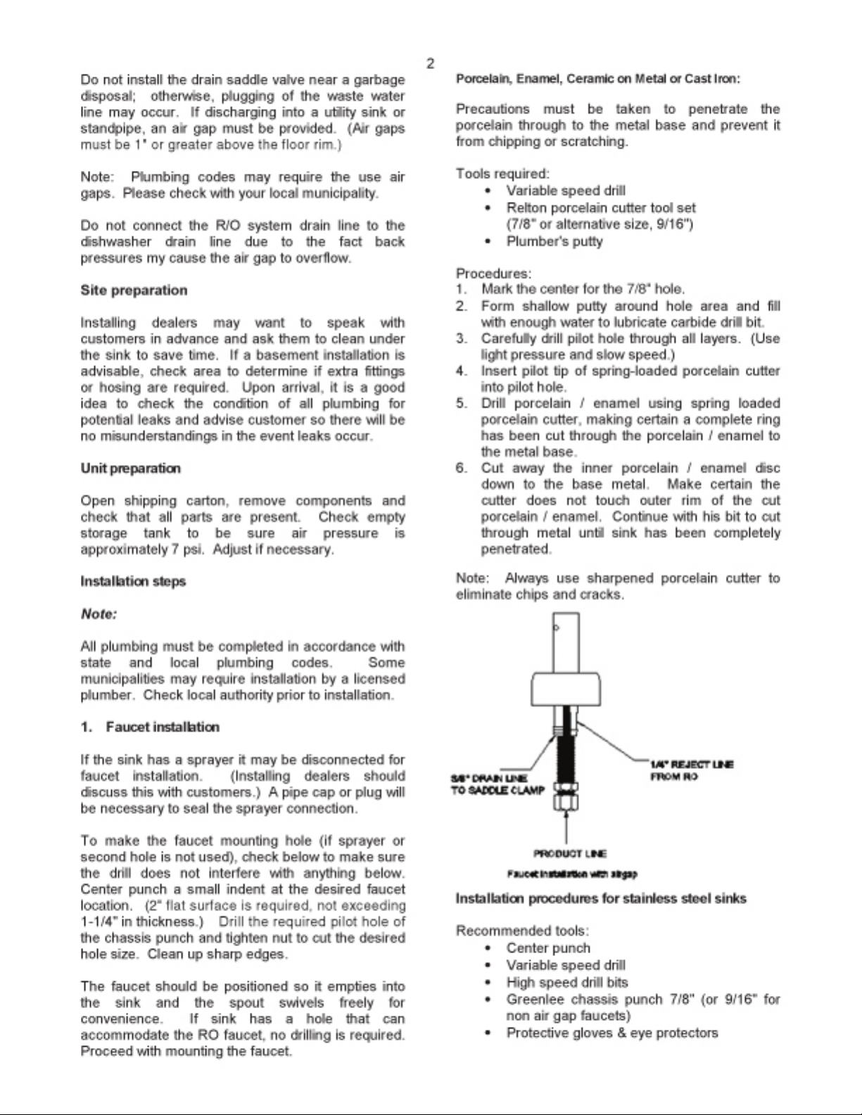
2. Mounting the faucet
Disassemble hardware from the threaded nipple,
except for chrome base plates and rubber washers.
(Rubber washers may be replaced with bead of
plumber's putty for neater appearance.)
Feed the threaded nipple through sink or counter
mounting hole and orient the faucet. From below
sink or counter, assemble the white spacer flat
washer and hex nut on threaded nipple and tighten
by hand. (Open end up; open side toward air gap).
After checking faucet orientation, tighten with a
wrench until secure.
3. Feed water valve and tubing installation
Thesaddle tapping valve which is supplied is
designed for use with 3/8" to 1/2" OD soft copper
supply tubing (plain or chromed) and rigid metal
pipe. Do not use with flexible ribbed supply tubing
which is too thin and requires special hardware.
Self-tapping feed water saddle valve installation
Installation procedures using soft copper tubing:
1. Turn off cold water valve from under sink or
main water line valve for whole house.
2. Before installing saddle tapping valve, make
sure piercing lance does not protrude beyond
rubber gasket.
3. Assemble saddle valve on copper tubing.
4. Turn handle clockwise to pierce soft copper
tube until valve is firmly seated. (Valve is
closed in this position.)
5. Turn on water supply to pressure cold water
line.
6. Snug nut/seal with wrench around valve stem.
7. Connect tubing to feed water valve using brass
compression nut,insert and plastic sleeve.
Saddle valve installations with metal pipe:
1. Turn off cold water supply.
2. Drill 3/16" hole at desired location.
3. At this point, make sure piercing lance does not
protrude beyond rubber gasket.
4. Assemble saddle on to pipe, aligning with hole.
5. Turn saddle valve handle clockwise to close
valve.
6. Tighten nut/seal around valve stem with
wrench.
7. Connect tubing to feed water valve using brass
compression nut,insert and plastic sleeve.
8. Turn on cold water supply.
9. To open valve, turn handle counterclockwise
and check for leaks.
4. Drain saddle valve installation
Prior to proceeding it is important to inspect the
condition of drain pipes to make sure they are not
thin and frail.
Drain saddle valves are designed to be installed on
standard 1-1/2" OD drain pipe. Install drain saddle
valve above (and before) the trap and on the
vertical or horizontal tailpiece. Never install a drain
saddle valve close to the outlet of a garbage
disposal or plugging of the RO drain line may result.
Drain saddle valve installation
Procedures
1. Position threaded half of drain saddle valve at
selected location and mark for the opening.
2. Drill 1/4" hole at mark through one side of pipe.
3. Position both halves of drain saddle on drain
pipe so threaded opening lines with hole.
4. Secure drain saddle clamp on valve with bolts
and nuts provided. (Do not over tighten and
make sure there isequal space between saddle
halves on each side.)
Valve handle
Reversible
backplate
Tightening
screw
Tubing to
RO inlet
Compression
nut
Brass
insert
Plastic ferrule
Brass
insert
1/4" Screw 1/4" Nut
Drain pipe
1/4" Drilled hole
Drain clamp
front plate
Page 5

4
5. Initial tubing connections
Forconvenience on under counter installations it
maybeadvisable to complete under counter hose
connections at this time.
6. RO component installation
Install RO membrane, carbon pre filer and sediment
pre filter in modules of RO unit. (Refer to RO
installation diagram.)
7. RO unit installation
The RO unit is normally mounted to the right or left
sink cabinet sidewall, depending on where supply
tank is to be located. Generally the unit is installed
at the front of the cabinet and the tank at the rear.
To mount the unit, elevate it at least 2" off the floor,
level it and mark the location of mounting holes
needed. Drill holes for mounting screws and install
screws, allowing the mounting bracket slots to slip
over them.
Note: If the cabinet sidewalls are not solid, unit
maysit on the floor with screws to keep it against
the cabinet in a vertical position.
8. Pre-fill, sanitizing and supply tank placement
Prefilling the storage tank is always recommended
so there is sufficient pressure to check for leaks and
sufficient water to flush the carbon post filter.
It is important to use a sanitizer (such as Clorox) so
tubing, fittings, tank and the faucet will be safe to
use upon start-up.
To pre-fill storage tank follow these directions:
1. Connect storage tank to feed water line.
2. Open feed water valve and valve on tank.
3. Allow to fill for approximately three minutes.
4. Turn off feed water valve and tank valve.
5. Do not flush tank for approximately 15 minutes.
Thesupply tank should be placed under the counter
or within 10 feet of the RO unit.
Note: Tanks are pre-pressurized at 7 psi. Prior to
installation, check, add or release as required.
9. Final tubingconnections
With all components in place, complete final tubing
connections using these guidelines:
Tubing should follow contour of the cabinets.
Cut tubing to desired length using square cuts
and proper cutting devise.
Make no sharp bends.
Keep tubing from the RO unit to the tank and
faucet as short as practical for good flow.
Under sink installations following installation
diagram and the following procedures:
1. Connect tubing from faucet to RO unit.
2. Connect tubing from tank to RO unit.
3. Connect tubing from supply valve to RO unit.
4. Connect tubing from drain valve to RO unit.
Icemaker hookup (optional)
The RO drinking water device can be connected to
any standard refrigerator ice maker or ice maker /
water dispenser. (Do not connect to a commercial
type bar ice maker.)
To complete this operation, connect a tee with shutoff valve into the faucet tubing and route tubing to
the refrigerator. (Hooking up to an existing copper
line is not recommended unless it is new
installation.) Shut off ice maker by lifting lever prior
to turning off the existing tap water supply line to
the refrigerator. Turn on ice maker after the RO
system has been drained several times and the
tank has a full supply of water.
Note: Before any service is preformed on the RO
system, turn off ice maker valve and ice maker unit.
Turn back only after RO tank is full.
System start-up
Prior to start-up
1. Check all connections be sure they are secure.
2. Turn on feed water valve and check for leaks.
(Turn off and correct leaks if leaks occur.)
3. Open valve on storage tank and open faucet
until a steady stream of water flows.
4. Close faucet and wait five minutes to see if
leaks result.
Note: When the system is first turned on, water
may intermittently"spurt" from the air gap opening
on the side of air gap faucets. This is common and
should correct itself after an initial period of time.
Flushing system and checking operation
To make sure RO system is operating correctly,
following these simple procedures:
1. Open faucet handle and allow tank to
completely drain of sanitizing solution.
Do not use this water.
Page 6

5
Note: When tank is empty, faucet will steadily
drip. This is the rate the RO system processes
water.
2. With faucet handle in "open" position, measure
the rate of the steady drip from spout. Use a
graduated cylinder and watch with a second
hand to calculate approximate production in
gallons per day.
Note:
Milliliters per minute X 0.38 = GPD.
Ounces per minute X 11.2 = GPD
3. Proceed to check reject flow rate by
disconnecting tubing at drain connection and
measure flow as described above.
Note: Proper ratio should be 3 reject water to
1 part of product water, on average.
4. Close faucet and re-inspect system for leaks.
5. Allow system to process water for
approximately four hours, at which point tank
will be practically full.
6. Open faucet again and allow tank to empty for a
second time.
Do not use this water.
7. Wait another four hours to allow tank to re-fill.
Note: If no objectionable tastes are noticed after
second tank draining, RO processed water is ready
for use. Otherwise, drain tank and re-fill for a third
time.
8. At this point supply line to ice maker connection
(optional) may be opened.
Maintenance
Your RO system contains filters and membranes
which must be replaced periodically for proper
operation. (Please see page 1 for general changeout recommendations.)
Note: Change-out procedures may be amended,
depending on source water conditions.
To change filters and membranes follow these
procedures:
1. Close feed water valve by turning it clockwise.
2. Open faucet to allow holding tank to drain.
3. Loosen and remove filter housings using
wrench provided and discard cartridges and or
membrane.
4. Wash the inside of the housings using mild
detergent and soft cloth. Thoroughly rinse all
soap before reassembly.
5. Replace filter cartridges and membrane before
sanitizing system.
Note: The system should besanitized before
installing the activated carbon post filter cartridge.
Sanitizing instructions
To sanitize system follow these procedures with the
feed watervalveclosed:
1. Remove pre-filters and membrane from
housings.
2. Use 5-1/4% unscented bleach such as Clorox.
3. Add one cap full (2 tsp or 10 ml) of bleach to
each pre-filter housing and membrane module.
4. Carefully refill housings with tap water and
temporarily replace without carbon cartridge,
sediment cartridge or membrane installed.
5. Slowly open the feed water line at faucet.
6. Close faucet as soon as water begins to drip
out of spout.
7. Let system stand for approximately 15 minutes.
8. After fifteen minutes do the following in order:
Close feed water valve.
Close holding tank valve while faucet is
open to release pressure.
9. Remove housings and empty them.
10. Remove any protective wrap from pre-filters
and membrane and install them in the
appropriate filter housings. Tighten with wrench.
11. Replace post carbon filter if necessary.
Note:
Be sure to check o-rings are in place when
installing cartridges in filter housings.
12. Disconnect product water tubing from the
holding tank and put 50 drops of bleach into the
tubing. Reconnect tubing.
13. Slowly open feed water saddle valve. When
water begins to drip from faucet, close faucet
and open holding tank valve.
14. Do not open faucet for at least eight (8) hours.
15. Discard the first two tanks of water produced,
as they contain chlorine. Do not use this
water.
16. When faucet is first opened, air and black
carbon powder may be noticed. This is normal.
Page 7

6
Water quality
Water quality from an RO system is normally
determined with a TDS Meter,
which measures total
dissolved solids in water, measuring conductivity.
The results are normally m eas ured in parts per
million or milligrams per liter. Fewer dissolved
solids results in higher quality water.
RO membranes are rated by the amount of
dissolved solids they reject, expressed as "rejection"
percentage". For example if feed water contains
100 ppm of dissolved solids and the product water
after th e membrane has 10 ppm
of dissolved solids
the rejection r ate is 90%. The formula is as f ollows:
Perc ent rejecti o n =
Feed water TDS– Product water TDS X 100%
Feed water TDS
Water production
Product water rate
Usable water producti on f rom an RO syste m is
designated product water rate, produced on a daily
basis. The rate is normally described in gallons per
day (gpd) or milliliters per minute (ml/min.).
Reject water rate
The flow of water to drain is designated as reject
water rate, as measured in gallons per day (gpd) or
milliliters per minute (ml/min.).
Using a graduated cylinder the formulas are:
Milliliters per minute X 0.38 = gallons per day
Ounces per minute X 11.2 =gallonsper day
Reject ratio
The reject ratio is the amount of water produced
compared to th e amount of water flowing to drain.
The form ula is as f ollows:
Rejec t rate
Rejec t rati o =
Pro duct rate
Percent recovery
The percent recovery is another way to m eas ure
the amount of water produced c ompared to the
amount of water which is actually used.
Theformula to determined percent recovery is as
follows:
Product water r ate X 100%
Perc ent recovery =
Feed water r ate
Note: Produc t water rate is th e sum of the f eed
water flow rate and reject water flow rate.
Exam ple:
Pro duct water rate =10 gpd
Rejec t water rate = 40 gpd
Feed water = 10 gp d + 40 gpdor50gpd
Perc ent recovery = 20%
Water pressure and temperature
Pro duct water quality and production of RO
systems is dependent on pressure and
tem peratu r e. Typically, RO mem branes are treated
at standard conditions of 77˚ F (25˚ C) and 60 ps i
(4 bar) discharging to atmosphere. In general, th e
higher the pressure differential and temperature,
increased quality and quantity of water is produced.
These facto rs sho uld be cons idered when sizing
RO systems for a particular application.
John Guest
®
brand fittings
Many RO systems utilize John Guest b rand fitt ings.
These user - friendly fittings provide superior
performance and may be provided with this system.
Pro per use of
these push-in fittings is shown below
Along with these fittings, all tubing selected must be
of high quality and must be cut with a plastic tube
cutter or sharp razor with a clean, square cut.
Should a leak occ ur at a fitting, the cause is
generally defective tubing. T
o fix a leak, relieve
pressure, release tubing, cut off at least 1/4" from
the end (square cut), reattach the tubing and
confirm the connection is leak free. Each time a
new connection is made, it is advisable to cut off
1/4" from th e end of th e tu bin g
using these fittings.
Conventional compression fittings
If John Guest f itt ings are not used, it is essential to
install inserts at th e ends of all tube connections
when conventional fittings are used.
To attach Tubing
Cut the tube square and push into the tube stop. For
metal tube, remove burrs and chamfer tube end to
prevent the "O" ring seal from being damaged. For soft
or thin walled plastic tubing we recommend the use
of a tube insert.
Pull the tube to check that it is secure. It is good
pratice to check the system before use.
Page 8

 Loading...