

Page 1
Instructions for Installing
FD-190-PR/190-PR-60 &
IS-WD-FD-190/290-PR
FD-290-PR/290-PR-60
Pronto!™ Adjustable Cast Iron and PVC
Floor Drains
!
WARNING
Read this Manual BEFORE using this equipment.
Failure to read and follow all safety and use information
can result in death, serious personal injury, property
damage, or damage to the equipment.
Keep this Manual for future reference.
WARNING
!
Local building or plumbing codes may require modifications to the information provided. You are required to
consult the local building and plumbing codes prior
to installation. If the information provided here is not
consistent with local building or plumbing codes, the
local codes should be followed. This product must be
installed by a licensed contractor in accordance with
local codes and ordinances.
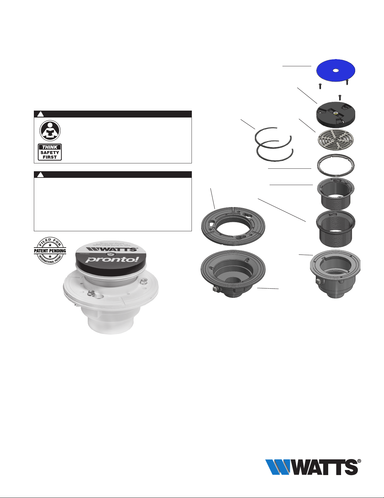
Shims for Leveling
PVC/CI Clamp
Collar
Label Protection for Top of Cap
Plastic Cap with Bubble Level
Nickel Bronze Grate
Nickel Bronze
Grate Ring
PVC/CI Strainer
Shank
PVC/CI Shank
Housing
PVC/CI
B4-34 Body
PVC/CI
B3-Body
FD-190
Body
FD-290
Body
Installation Guidelines
General Note: Please consult all local plumbing codes before installing
Watts Pronto!™ floor drains.
Watts Pronto!™ floor drains are designed for pre- and post-pour adjustment with flexibility in mind.
Pronto!™ delivers an integrated built-in bubble level for ease of installation and is pre-packaged with
shims for tilt correction.
Pronto!™ is designed for light to medium commercial and residential applications and comes in
both cast iron and PVC. PVC drains offer the unique ability for easy installation while giving durability
for the long haul. Cast iron is durable and designed with ease of installation in mind. Both drains are
adjustable and meet the requirements of a durable adjustable floor drain.
Page 2
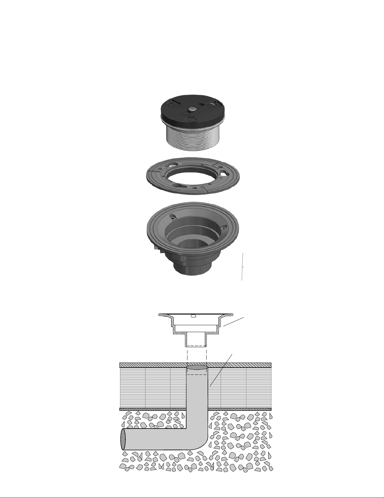
Typical Installation
Note:
Pronto!™ floor drains arrive assembled and must be partially
disassembled before installation.
Plastic top assembly with bubble level should remain on the drain until drain is securely installed
and concrete cured. The plastic top assembly is designed to keep the nickel bronze grate from
being damaged during installation and keeps concrete from entering the drain.
Note:
Make sure cover is snug
Plastic Top Assembly
w/Grate & Shank
but do not over tighten
Clamping Collar
Drain Body
1. Leader Pipe
Leader pipe should be cut so that the height of the finished drain is at or just below the height of
the finished floor. The leader pipe should be cut evenly with no burrs or debris attached.
Drain Body
Leader Pipe
2
Page 3
2. Drain Body
Attach the drain body securely to the leader pipe. Use the bubble level on top of the plastic
cap to level the drain body evenly before concrete is poured. Check local code requirements
before pressure testing the connection. Plastic drain body should be solvent welded to the
pipe. Cast iron body will be no hub or push on (specify).
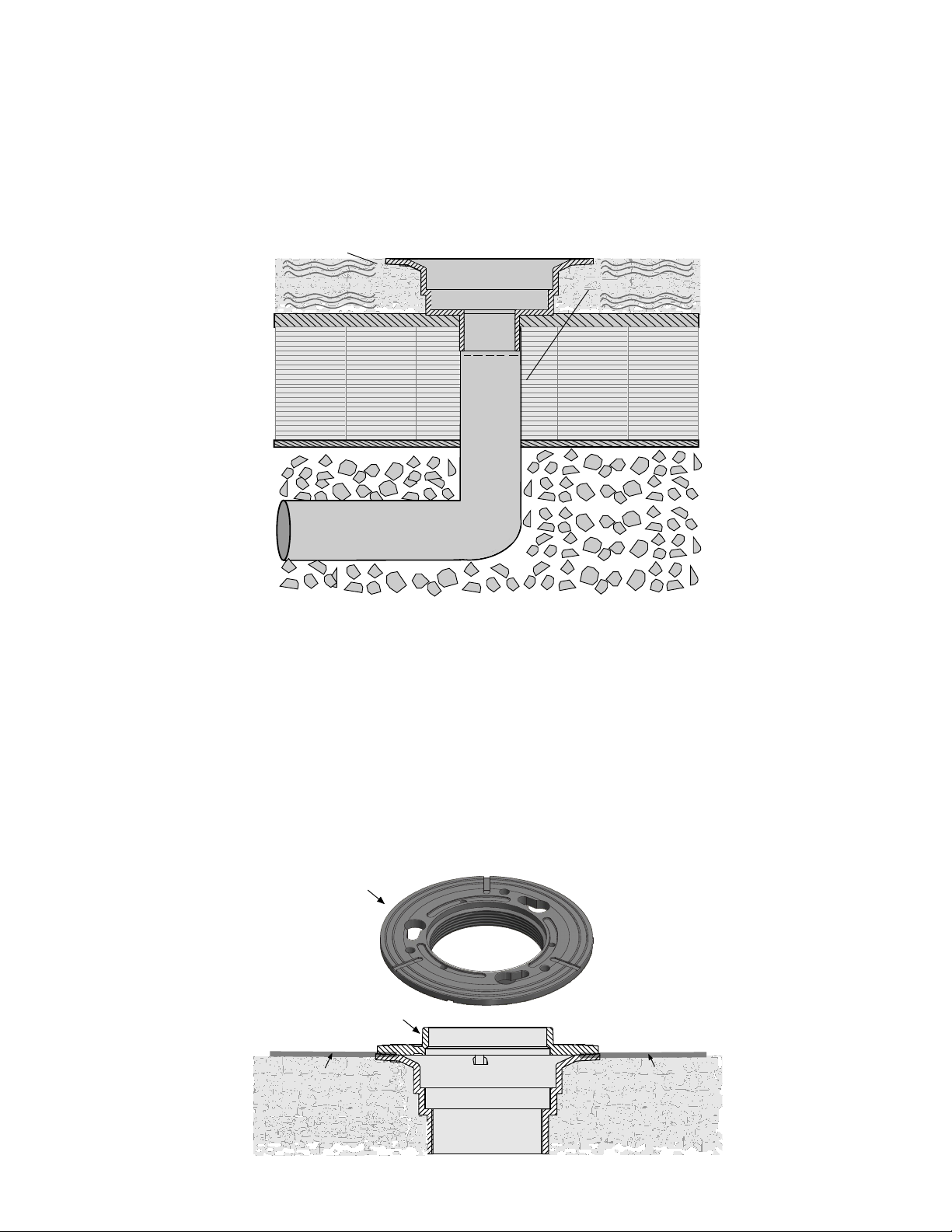
3. Concrete
Concrete floor should be poured flush with the top of the drain body.
Drain Body
Concrete Concrete
Leader Pipe
4. Waterproofing Membrane
Waterproofing membrane is used per the manufacturers instructions.
Clamping collar must be removed while installing waterproofing membrane.
Waterproofing membrane sits on top of the drain body. Clamp collar attaches to the
drain body clamping the waterproofing membrane between the two. Small grooves
in the clamp collar allow water to flow off the membrane, through the slits and into
the drain. Clamp collar is secured with screws (provided). Screws should be
inserted with a maximum torque of 8 ft-lbs.
Note: Clamp collar inverts for a lower rough-in height.
Clamping Collar
Clamping Collar
Waterproong
Membrane
Waterproong
Membrane
3
Page 4
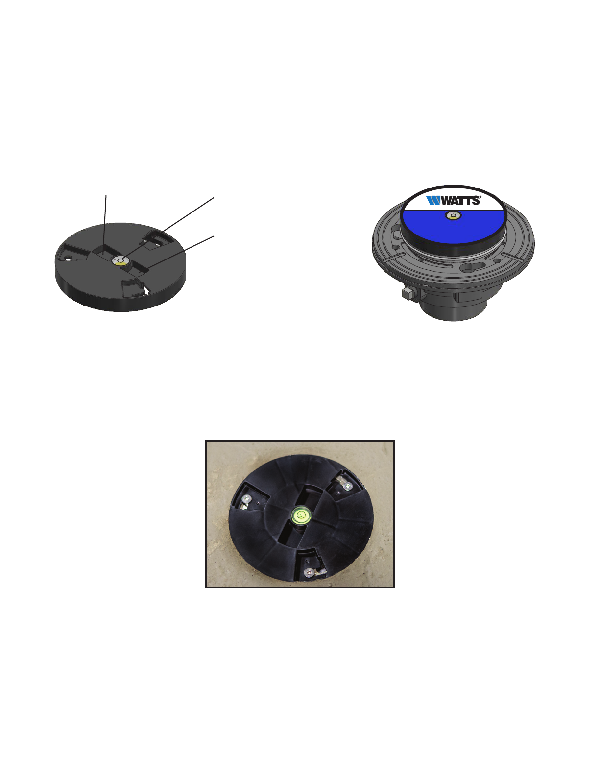
5. Plastic Top Assembly
Adjust the top of the drain with the plastic cover in place by screwing it into the drain body until
the top of the cover is flush with finish floor grade.
Plastic top assembly should sit tight against the clamping collar ensuring that no concrete seeps
into the drain assembly. Make sure cover is snug but do not over tighten.
Removable Top
Assembly With
Bubble Level
Recessed Slot
Bubble Level
Recessed Slot
Pronto
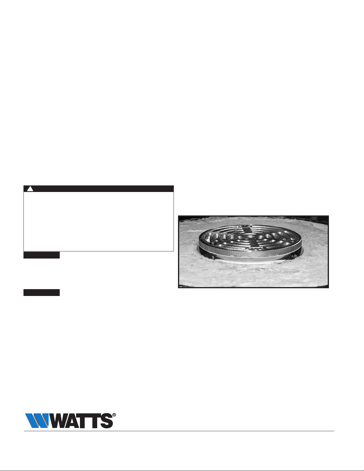
6. Finish Floor
Finished floor slab should be poured flush with the top of the plastic leveling cap.
The floor surface may require hand finishing the concrete if the drain is above the
floor surface.
View After Concrete
Is Poured & Label
Is Removed
7. Removing Protective Label & Plastic Cap
• Once concrete is cured, remove the protective label on top of the plastic top
assembly to expose the two recessed slots on each side to the bubble level.
• Loosen the three 10-24 screws.
• Adjustable pliers may be needed to break the plastic top assembly loose from
the concrete seal.
• Use the back of the pliers, or a hammer to tap against the plastic top assembly.
4
Page 5
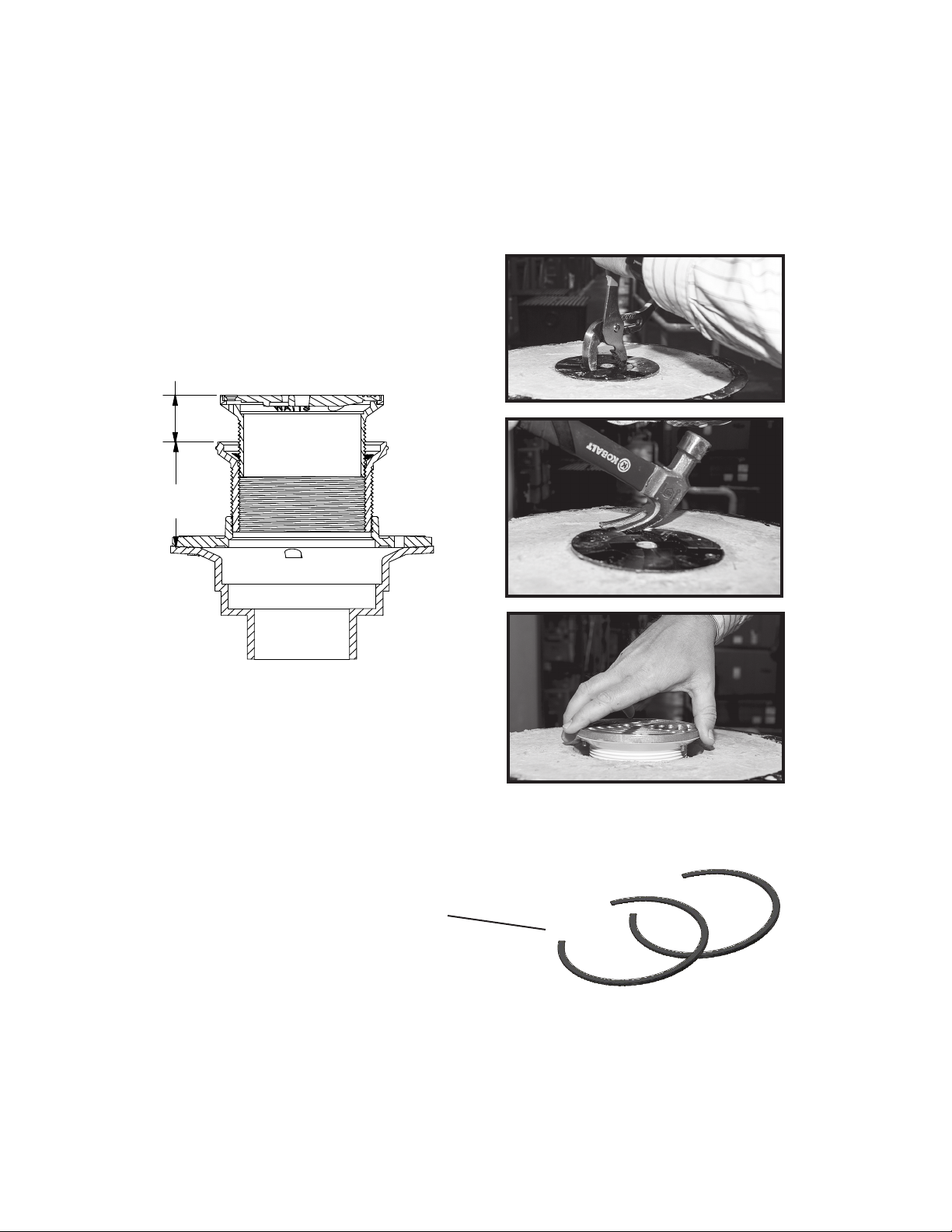
0-7/8" Adj.
After Pour
3 3/8"
(85)
• Continue tapping until a visible crack forms around the edge of the top assembly.
• The top should loosen and separate from the concrete by using the pliers to
grasp the edge tabs around the recessed screw holes and popping the top up.
(A straight edge screwdriver may also be used to pry the top up)
Do not use excessive force when tapping against the cover. Excessive
force may cause pliers to slip and cause damage to the concrete floor.
Adjust After
Concrete Pour
8. Shims
The Pronto!™ floor drain comes equipped with two plastic leveling shims. These
may be used when the finished drain assembly is slightly tilted.
Leveling Shims
On-Grade Slab Installation
It is recommended to use a bead of silicone around the last thread of the top
assembly.
Screw the top assemby down until the bottom of the frame is flush with the
concrete.
Use a bead of silicone around the perimeter of the strainer frame.
Gently turn the head clockwise until the top of the strainer sits flush with the finish
floor.
5
Page 6
Cleaning & Maintaining Pronto!™ Floor Drain
Pronto!™ floor drains should be inspected periodically to ensure maximum
performance. If drain becomes clogged with dirt and debris, it will significantly lower
the amount of water that flows into and through the drain.
Maintenance
First remove the three screws that hold the strainer in place.
Lift strainer off and lay aside.
Grip the top adjustable strainer shank and screw it up and out of the drain. Lay
aside. The shank may need to be wiped down if the sides come in contact with
dirt and debris.
Use gloved hands or tools to remove any dirt and debris that may have entered or
clogged the drain body.
Flush drain with water to make sure that is working properly.
Screw the strainer shank back into the drain body and adjust to correct height.
Petroleum jelly may be used around the shank for easing the process.
Apply the top strainer and insert screws.
!
WARNING
Need for Periodic Inspection/Maintenance: This product
must be tested periodically in compliance with local codes,
but at least once per year or more as service conditions
warrant. All products must be retested once maintenance
has been performed. Corrosive water conditions and/or
unauthorized adjustments or repair could render the product
ineffective for the service intended. Regular checking and
cleaning of the product’s internal and external components
helps assure maximum life and proper product function.
NOTICE
The information contained herein is not intended to replace the full
product installation and safety information available or the experience of
a trained product installer. You are required to thoroughly read all installation instructions and product safety information before beginning the
installation of this product.
NOTICE
Inquire with governing authorities for local installation
requirements
Limited Warranty: Watts Regulator CO. (the “Company”) warrants each product to be free from defects in material and workmanship under normal usage for a period of one year from the date of
original shipment. In the event of such defects within the warranty period, the Company will, at its option, replace or recondition the product without charge.
THE WARRANTY SET FORTH HEREIN IS GIVEN EXPRESSLY AND IS THE ONLY WARRANTY GIVEN BY THE COMPANY WITH RESPECT TO THE PRODUCT. THE COMPANY MAKES NO OTHER
WARRANTIES, EXPRESS OR IMPLIED. THE COMPANY HEREBY SPECIFICALLY DISCLAIMS ALL OTHER WARRANTIES, EXPRESS OR IMPLIED, INCLUDING BUT NOT LIMITED TO THE IMPLIED
WARRANTIES OF MERCHANTABILITY AND FITNESS FOR A PARTICULAR PURPOSE.
The remedy described in the first paragraph of this warranty shall constitute the sole and exclusive remedy for breach of warranty, and the Company shall not be responsible for any incidental, special
or consequential damages, including without limitation, lost profits or the cost of repairing or replacing other property which is damaged if this product does not work properly, other costs resulting
from labor charges, delays, vandalism, negligence, fouling caused by foreign material, damage from adverse water conditions, chemical, or any other circumstances over which the Company has no
control. This warranty shall be invalidated by any abuse, misuse, misapplication, improper installation or improper maintenance or alteration of the product.
Some States do not allow limitations on how long an implied warranty lasts, and some States do not allow the exclusion or limitation of incidental or consequential damages. Therefore the above
limitations may not apply to you. This Limited Warranty gives you specific legal rights, and you may have other rights that vary from State to State. You should consult applicable state laws to
determine your rights. SO FAR AS IS CONSISTENT WITH APPLICABLE STATE LAW, ANY IMPLIED WARRANTIES THAT MAY NOT BE DISCLAIMED, INCLUDING THE IMPLIED WARRANTIES OF
MERCHANTABILITY AND FITNESS FOR A PARTICULAR PURPOSE, ARE LIMITED IN DURATION TO ONE YEAR FROM THE DATE OF ORIGINAL SHIPMENT.
USA: Tel: (800) 338-2581 • Fax: (828) 248-3929 • Watts.com
Canada: Tel: (905) 332-4090 • Fax: (905) 332-7068 • Watts.ca
Latin America: Tel: (52) 81-1001-8600 • Watts.com
IS-WD-FD-190/290-PR 1916 EDP#1915442 © 2019 Watts
Page 7

Instrucciones para
instalar FD-190-PR/190-
IS-WD-FD-190/290-PR
PR-60 y FD-290-PR/290PR-60
Drenajes de piso de hierro fundido y PVC
ajustables Pronto!™
!
ADVERTENCIA
Lea este manual ANTES de utilizar este equipo.
El no leer y no seguir toda la información de seguridad
y uso puede causar muerte, lesiones personales graves,
PIENSE
PRIMERO EN
LA SEGURIDAD
ADVERTENCIA
!
La información proporcionada podría requerir de
modificaciones con base en las normativas locales de
construcción o plomería. Es necesario que consulte las
normativas locales de construcción y plomería antes de realizar
la instalación. Si la información que aquí se proporciona no
es consistente con las normativas locales de construcción o
plomería, debe seguir las normativas locales. Un contratista
autorizado debe instalar este producto de acuerdo con las
normativas y ordenanzas locales.
daños a la propiedad o daños al equipo.
Conserve este manual para referencia futura.
Cuñas para nivelación
Collar de jación
de PVC/CI
Carcasa de vástago
Protección de etiqueta para
la parte superior de la tapa
Tapa de plástico con nivel de burbuja
Rejilla de bronce de níquel
Anillo de rejilla de
bronce de níquel
Vástago del ltro de
PVC/hierro fundido
(cast iron, CI)
de PVC/CI
Cuerpo de
PVC/CI B4-34
Cuerpo de
PVC/CI B3
Cuerpo de
FD-190
Cuerpo de
FD-290
Lineamientos de instalación
Nota general: Consulte todas las normativas locales de plomería antes de
instalar los drenajes de piso Pronto de Watts.
Los drenajes de piso Pronto!™ de Watts están diseñados para el ajuste previo y posterior al vertido tomando
en cuenta la flexibilidad. Pronto!™ proporciona un nivel con burbuja integrado para facilitar la instalación y se
empaca previamente con cuñas para corregir la inclinación.
Pronto!™ está diseñado para aplicaciones comerciales y residenciales ligeras a medianas y se maneja en
hierro fundido así como en PVC. Los drenajes de PVC ofrecen la capacidad única de una instalación sencilla
al mismo tiempo que ofrecen durabilidad a largo plazo. El hierro fundido es duradero y está diseñado teniendo
en cuenta la facilidad de instalación. Ambos drenajes son ajustables y cumplen los requisitos de un drenaje de
piso ajustable y duradero.
Page 8

Instalación típica
Nota:
Los drenajes de piso Pronto!™ llegan ensamblados y deben desensamblarse
parcialmente antes de la instalación.
El ensamble superior de plástico con nivel de burbuja debe permanecer en el drenaje hasta que el drenaje
esté bien instalado y el concreto haya curado. El ensamble superior de plástico está diseñado para evitar
que la rejilla de bronce de níquel se dañe durante la instalación y evita que el concreto entre en el drenaje.
Nota:
Asegúrese de que
Ensamble superior de plástico
con rejilla y vástago
la cubierta esté bien
ajustada pero no apriete
demasiado
Collar de fijación
Cuerpo del drenaje
1. Tubo guía
El tubo guía debe cortarse de manera que la altura del drenaje terminado esté a la altura del piso
terminado o justo por debajo. El tubo guía debe cortarse de forma uniforme sin que contenga rebabas ni
desechos.
Cuerpo del drenaje
Tubo guía
2
Page 9

2. Cuerpo del drenaje
Fije el cuerpo del drenaje de forma segura al tubo guía. Utilice el nivel de burbuja sobre la tapa de plástico
para nivelar el cuerpo del drenaje de forma uniforme antes de verter el concreto. Compruebe los requisitos
de la normativa local antes de comprobar la presión de la conexión. El cuerpo del drenaje de plástico
se debe unir con solvente a la tubería. El cuerpo de hierro fundido será drenaje para residuos
indirectos o de botón (especifique).
3. Concreto
El piso de concreto debe vaciarse de manera que quede nivelado con la parte superior
del cuerpo del drenaje.
Cuerpo del drenaje
Concreto Concreto
Tubo guía
4. Membrana impermeabilizante
La membrana impermeabilizante se usa de acuerdo con las instrucciones del fabricante.
El collar de fijación se debe retirar mientras se instala la membrana impermeabilizante.
La membrana impermeabilizante se asienta en la parte superior del cuerpo del
drenaje. El collar de fijación se coloca en el cuerpo del drenaje que sujeta la membrana
impermeabilizante entre las dos. Las ranuras pequeñas del collar de fijación permiten que
el agua fluya de la membrana, a través de las ranuras y en el drenaje. El collar de fijación
está sujeto con tornillos (provistos). Los tornillos deben insertarse con una torsión máxima
de 8 pies-lb (10.85Nm).
Nota: El collar de fijación se invierte para obtener una altura de esbozo más baja.
Collar de jación
Collar de jación
Membrana
impermeabilizante
Membrana
impermeabilizante
3
Page 10

5. Ensamble superior de plástico
Ajuste la parte superior del drenaje con la cubierta de plástico en su lugar atornillándola en el cuerpo del
drenaje hasta que la parte superior de la cubierta quede nivelada con el piso terminado.
El ensamble superior de plástico debe quedar ajustado contra el collar de fijación, asegurándose de que no
ingrese concreto en el ensamble del drenaje. Asegúrese de que la cubierta esté ajustada pero no
apriete demasiado.
Ensamble superior
extraíble con
nivel de burbuja
Ranura ahuecada
Nivel de burbuja
Ranura ahuecada
Pronto
6. Piso de acabado
La losa del piso acabado debe quedar nivelada con la parte superior de la tapa de
nivelación de plástico. La superficie del piso puede requerir que el concreto se termine a
mano si el drenaje está por encima de la superficie del piso.
Vista después de que el
concreto se vierte y se
haya retirado la etiqueta
7. Eliminación de la etiqueta protectora y de la tapa de plástico
• Una vez que el concreto esté curado, retire la etiqueta protectora en la parte superior
del ensamble superior de plástico para exponer las dos ranuras ahuecadas a cada lado
del nivel de burbuja.
• Afloje los tres tornillos 10-24.
• Es posible que se necesiten pinzas ajustables para desprender el ensamble superior de
plástico del sello de concreto.
• Utilice la parte posterior de las pinzas, o un martillo, para golpear contra el ensamble
superior de plástico.
4
Page 11

0-7/8" (0-22 mm)
de ajuste después
del vaciado
3 3/8"
(85 mm)
• Siga golpeando hasta que se forme una grieta visible alrededor del borde del ensamble
superior.
• Utilice las pinzas para aflojar y separar la parte superior del concreto para sujetar las
lengüetas del borde alrededor de los orificios ahuecados de los tornillos y hacer que
se bote la parte superior. (También puede utilizar un destornillador plano para hacer
palanca en la parte superior)
No aplique demasiada fuerza al golpear contra la cubierta. El uso de fuerza
excesiva puede provocar que las pinzas se resbalen y puede causar daños en el
piso de concreto.
Ajustar después
de vaciar el
concreto
8. Cuñas
El drenaje de piso Pronto!™ viene equipado con dos cuñas de nivelación de plástico.
Instalación de placa con ángulo
Se recomienda aplicar una gota de silicón alrededor de la última rosca del ensamble
Atornille el ensamble de la parte superior hacia abajo hasta que la parte inferior del marco
Utilice una gota de silicón alrededor del perímetro del marco del filtro.
Gire suavemente la cabeza en el sentido de las manecillas del reloj hasta que la parte
Estas pueden utilizarse cuando el ensamble del drenaje terminado esté ligeramente
inclinado.
Cuñas de nivelación
superior.
quede nivelada con el concreto.
superior del filtro quede nivelada con el piso terminado.
5
Page 12

Limpieza y mantenimiento de un drenaje de piso Pronto!™
Los drenajes de piso Pronto!™ deben inspeccionarse periódicamente para asegurar el
máximo rendimiento. Si el drenaje se obstruye con suciedad y residuos, esto reducirá
significativamente la cantidad de agua que fluye hacia dentro y por el drenaje.
Mantenimiento
Primero retire los tres tornillos que sujetan el filtro en su sitio.
Levante el filtro y colóquelo a un lado.
Sujete el vástago del filtro ajustable superior y desatorníllelo para sacarlo del drenaje.
Colóquelo a un lado. Es posible que deba limpiar el vástago si los lados entran en
contacto con suciedad y residuos.
Utilice guantes o herramientas para eliminar cualquier suciedad y residuos que puedan
haber ingresado al cuerpo del drenaje o lo hayan obstruido.
Enjuague el drenaje con agua para asegurarse de que funciona correctamente.
Vuelva a atornillar el vástago del filtro en el cuerpo del drenaje y ajústelo a la altura
correcta.
Puede utilizar vaselina alrededor del vástago para facilitar el proceso.
Coloque el filtro superior e inserte los tornillos.
!
ADVERTENCIA
Necesidad de inspección/mantenimiento periódicos: Se
debe probar periódicamente este producto para verificar el
cumplimiento con las normativas locales, pero por lo menos
una vez al año o con más frecuencia según lo requieran las
condiciones de servicio. Se deben volver a probar todos los
productos después de realizar un servicio de mantenimiento.
Condiciones de agua corrosiva o ajustes o reparaciones no
autorizados pueden provocar que el producto no sea efectivo
para el servicio previsto. La verificación y limpieza periódicas
de los componentes internos y externos del producto ayudan
a garantizar la máxima vida útil y el funcionamiento adecuado
del producto.
AVISO
La información aquí contenida no tiene como objetivo sustituir la
información completa disponible sobre la instalación y seguridad del
producto o la experiencia de un instalador capacitado en el producto.
Usted está obligado a leer con atención todas las instrucciones de
instalación y la información de seguridad del producto antes de instalar
este producto.
AVISO
Consulte con las autoridades competentes para conocer los
requisitos de instalación local
Garantía limitada: Watts Regulator CO. (la “Compañía”) garantiza que cada producto estará libre de defectos en el material y mano de obra cuando se usen de forma normal durante un periodo de un
año a partir de la fecha de envío original. En caso de que se presenten tales defectos dentro del período de garantía, la Compañía, a su discreción, reemplazará o reacondicionará el producto sin cargo.
LA GARANTÍA QUE AQUÍ SE ESTABLECE SE BRINDA EXPRESAMENTE Y ES LA ÚNICA GARANTÍA QUE OTORGA LA COMPAÑÍA CON RESPECTO AL PRODUCTO. LA COMPAÑÍA NO OTORGA NINGUNA
OTRA GARANTÍA, EXPRESA O IMPLÍCITA. POR MEDIO DE LA PRESENTE, LA COMPAÑÍA ESPECÍFICAMENTE SE DESLINDA DE CUALQUIER OTRA GARANTÍA, EXPRESA O IMPLÍCITA, ENTRE OTRAS,
LAS GARANTÍAS IMPLÍCITAS DE COMERCIABILIDAD E IDONEIDAD PARA UN FIN PARTICULAR.
El recurso que se describe en el primer párrafo de esta garantía conformará el único y exclusivo recurso en caso de incumplimiento de la garantía, y la Compañía no asume responsabilidad por ningún
daño incidental, especial o consecuencial, entre otras sin limitación, ganancias pérdidas o el costo de reparar o reemplazar otra propiedad dañada si este producto no funciona de manera adecuada,
otros costos que resulten de cargos laborales, retrasos, vandalismo, negligencia, mal olor ocasionado por materia extraña, daño por condiciones adversas del agua, sustancias químicas o cualquier
otra circunstancia de la cual la Compañía no tiene control. Cualquier abuso, mal uso, aplicación errónea, instalación o mantenimiento inadecuados o alteración del producto anulan esta garantía.
Algunos estados no permiten limitaciones en la duración de una garantía implícita, y algunos estados no permiten la exclusión o la limitación de daños incidentales o consecuentes. Por lo tanto, es
posible que las limitaciones anteriores no correspondan a usted. Esta garantía limitada le otorga derechos legales específicos, y es posible que usted tenga otros derechos que varían según el estado.
Debe consultar las leyes estatales correspondientes para determinar sus derechos. HASTA AHORA, SEGÚN LEYES ESTATALES CORRESPONDIENTES, CUALQUIER GARANTÍA IMPLÍCITA QUE NO
PUEDA RENUNCIARSE, INCLUIDAS LAS GARANTÍAS IMPLÍCITAS DE COMERCIABILIDAD E IDONEIDAD PARA UN FIN PARTICULAR, ESTÁN LIMITADAS EN DURACIÓN A UN AÑO A PARTIR DE LA
FECHA DE EMBARQUE ORIGINAL.
EE.UU.: Tel.: (800) 338-2581 • Fax: (828) 248-3929 • Watts.com
Canadá: Tel.: (905) 332-4090 • Fax: (905) 332-7068 • Watts.ca
América Latina: Tel.: (52) 81-1001-8600 • Watts.com
IS-WD-FD-190/290-PR 1916 EDP#1915442 © 2019 Watts
Page 13

Instructions pour l’installation
du FD-190-PR/190-PR-60 et du
IS-WD-FD-190/290-PR
FD-290-PR/290-PR-60
Drains de plancher réglables en fonte
et en PVC Pronto!™
!
AVERTISSEMENT
Lisez ce manuel AVANT d’utiliser cet équipement.
Le non-respect de toutes les instructions de sécurité
et d’utilisation de ce produit peut endommager ce
LA SÉCURITÉ
AVANT
TOUT
AVERTISSEMENT
!
Les codes du bâtiment ou de plomberie locaux peuvent
nécessiter des modifications à l’information fournie. Vous
êtes tenu de consulter les codes du bâtiment et de plomberie
locaux avant l’installation. Si les informations fournies ne sont
pas compatibles avec les codes du bâtiment ou de plomberie
locaux, les codes locaux prévalent. Ce produit doit être
installé par un entrepreneur certifié et respecter les codes et
ordonnances locaux.
produit ou entraîner d’autres dommages matériels, des
blessures graves ou la mort.
Conservez ce manuel pour référence ultérieure.
Cales pour nivellement
Collier de serrage
en PVC/CI
Protection des étiquettes pour le
Bouchon en plastique avec niveau à bulle
dessus du bouchon
Grille en bronze au nickel
Anneau de grille en
bronze au nickel
Tige de la crépine
en PVC/CI
Boîtier à tige en
PVC/CI
Corps en
PVC/CI B4-34
Corps en
PVC/CI B3
FD-190
Corps
FD-290
Corps
Directives d’installation
Remarque générale: veuillez consulter tous les codes locaux de
plomberie avant l’installation des drains de plancher Pronto!™ de Watts.
Les drains de plancher Pronto!™ de Watts sont conçus pour un ajustement avant et après le versement, en
gardant la flexibilité à l’esprit. Pronto!™ offre un niveau à bulle intégré pour faciliter l’installation et est préemballé avec des cales pour la correction de l’inclinaison.
Pronto!™ est conçu pour les applications commerciales et résidentielles légères à moyennes, et est disponible
en fonte et en PVC. Les drains en PVC offrent la capacité unique d’une installation facile tout en offrant une
durabilité à long terme. La fonte est durable et conçue pour la facilité d’installation. Les deux drains sont
réglables et répondent aux exigences d’un drain de plancher réglable et durable.
Page 14

Installation typique
Remarque:
Les drains de plancher Pronto!™ sont livrés assemblés et doivent être partiellement
démontés avant l’installation.
L’ensemble supérieur en plastique avec le niveau à bulle doit rester sur le drain jusqu’à ce que le drain soit
solidement installé et que le béton soit durci. L’ensemble supérieur en plastique est conçu pour empêcher
la grille en bronze de s’endommager pendant l’installation et empêche le béton de pénétrer dans le drain.
Remarque:
Assurez-vous que le
Ensemble supérieur en
plastique avec grille et tige
couvercle est bien ajusté,
mais ne serrez pas trop
Collier de serrage
Corps du drain
1. Tuyau conducteur
Le tuyau conducteur doit être coupé de façon à ce que la hauteur du drain fini soit à la hauteur du
plancher fini, ou juste en dessous de celui-ci. Le tuyau conducteur doit être coupé uniformément et
proprement, sans bavures ni débris.
Corps du drain
Tuyau conducteur
2
Page 15

2. Corps du drain
Fixez fermement le corps du drain au tuyau conducteur. Utilisez le niveau à bulle sur le dessus du bouchon en
plastique pour mettre de niveau le corps du drain avant que le béton ne soit versé. Vérifiez les exigences du
code local avant de tester la pression. Le corps du drain en plastique doit être soudé par solvant sur le
tuyau. Le corps en fonte ne sera pas un moyeu ni à pousser (préciser).
3. Béton
Le plancher en béton doit être versé égal au haut du corps du drain.
Corps du drain
Béton Béton
Tuyau conducteur
4. Membrane d’étanchéité
La membrane d’étanchéité est utilisée conformément aux instructions du fabricant. Le
collier de serrage doit être retiré lors de l’installation d’une membrane d’étanchéité. La
membrane d’étanchéité repose sur le dessus du corps du drain. Le collier de serrage
se fixe au corps du drain, serrant la membrane d’étanchéité entre les deux. Les petites
rainures du collier de serrage permettent d’évacuer l’eau de la membrane, à travers les
fentes et dans le drain. Collier de serrage fixé à l’aide de vis (fournies). Les vis doivent être
insérées avec un couple maximum de 8pi-lb.
Remarque: le collier de serrage s’invertit pour une hauteur préliminaire plus basse.
Collier de serrage
Collier de serrage
Membrane
d’étanchéité
Membrane
d’étanchéité
3
Page 16

5. Ensemble supérieur en plastique
Réglez le haut du drain avec le couvercle en plastique en place en le vissant dans le corps du drain, jusqu’à
ce que le haut du couvercle soit de niveau avec le plancher fini. L’ensemble supérieur en plastique doit
être serré contre le collier de serrage, assurant qu’aucun béton ne pénètre dans l’ensemble de drainage.
Assurez-vous que le couvercle est bien ajusté, mais ne serrez pas trop.
Ensemble supérieur
amovible avec
niveau à bulle
Fente encastrée
Niveau à bulle
Fente encastrée
Pronto
6. Plancher fini
La dalle du plancher fini doit être versée égale au haut du capuchon de mise à niveau en
plastique. La surface du plancher peut nécessiter une finition manuelle du béton si le drain
est au-dessus de la surface du plancher.
Vue après que le béton
est versé et l’étiquette
est retirée
7. Retrait de l’étiquette de protection et du capuchon en plastique
• Lorsque le béton est durci, retirez l’étiquette de protection sur le dessus de l’ensemble
supérieur en plastique pour exposer les deux fentes encastrées de chaque côté au
niveau à bulle.
• Desserrez les trois vis10-24.
• Des pinces réglables peuvent être nécessaires pour libérer l’ensemble supérieur en
plastique du joint en béton.
• Utilisez l’arrière de la pince ou un marteau pour taper contre l’ensemble supérieur en
plastique.
4
Page 17

Ajustement de
0 à 7/8 po (0 à 22 mm)
après le versement
3 3/8"
(85)
• Continuez à taper jusqu’à ce qu’une fissure visible se forme autour du bord de
l’ensemble supérieur.
• Le couvercle devrait se desserrer et se séparer du béton en utilisant la pince pour saisir
les languettes de bord autour des trous de vis encastrés et en tirant le dessus vers le
haut. (Un tournevis à bord droit peut également être utilisé pour soulever le couvercle).
N’utilisez pas de force excessive lorsque vous tapez contre le couvercle. Une
force excessive peut faire plier les pinces et endommager le plancher en béton.
Ajustez après le
versement du béton
8. Cales
Le drain de plancher Pronto!™ est équipé de deux cales de nivellement en plastique.
Celles-ci peuvent être utilisées lorsque l’ensemble de drainage complété est légèrement
incliné.
Installation de la dalle sur le plancher
On recommande d’utiliser un cordon de silicone autour du dernier filetage de l’ensemble
supérieur.
Vissez l’ensemble supérieur jusqu’à ce que le fond du cadre soit aligné avec le béton.
Utilisez un cordon de silicone autour du périmètre du cadre de la crépine.
Tournez doucement la tête dans le sens horaire jusqu’à ce que le haut de la crépine soit
égal au plancher fini.
Cales de nivellement
5
Page 18

Nettoyage et entretien du drain de plancher Pronto!™
Les drains de plancher Pronto!™ doivent être inspectés périodiquement afin d’assurer
une performance maximale. Si le drain est obstrué par de la saleté et des débris, cela
diminuera considérablement la quantité d’eau qui circule dans le drain.
Entretien
Retirez d’abord les trois vis qui tiennent la crépine en place.
Soulevez la crépine et mettez-la de côté.
Saisissez la tige de crépine réglable supérieure et sortez-la du drain. Mettez de côté. Il
faudra peut-être essuyer la tige si les côtés entrent en contact avec la saleté et les débris.
Utilisez des mains gantées ou des outils pour éliminer toute saleté et tout débris qui
auraient pu pénétrer ou obstruer le corps du drain.
Rincez le drain avec de l’eau pour s’assurer qu’il fonctionne correctement.
Revissez la tige de la crépine dans le corps du drain et ajustez-la pour corriger la hauteur.
La gelée de pétrole peut être utilisée autour de la tige pour faciliter le processus.
Appliquez la crépine supérieure et insérez les vis.
!
AVERTISSEMENT
Inspection/entretien périodique nécessaire: ce produit
doit être testé périodiquement et en conformité avec les
codes locaux, mais au moins une fois par an, ou plus selon
les conditions de service. Tous les produits doivent être testés
une fois l’entretien terminé. Un environnement avec de l’eau
corrosive, ou des réglages ou des réparations non autorisés
peuvent rendre le produit inefficace pour le service prévu. La
vérification et le nettoyage réguliers des composants internes
et externes du produit contribuent à assurer une durée de vie
maximale et un bon fonctionnement du produit.
AVIS
Ces informations ne sont pas destinées à remplacer les informations
d’installation et de sécurité complètes du produit ni l’expérience d’un
installateur professionnel. Vous êtes tenu de lire attentivement toutes
les instructions d’installation et les informations relatives à la sécurité du
produit avant de commencer l’installation de ce produit.
AVIS
Renseignez-vous auprès des autorités de réglementation pour
connaître les exigences d’installation locales
Garantie limitée: Watts Regulator Co. (la «Société») garantit que chacun de ses produits est exempt de vice de matériau et de fabrication dans des conditions normales d’utilisation, pour une période
d’un an à compter de la date d’expédition d’origine. Si une telle défaillance devait se produire au cours de la période sous garantie, la Société aura à sa discrétion les options suivantes: le remplacement
ou bien la remise en état du produit, sans frais pour le demandeur.
LA PRÉSENTE GARANTIE EXPRESSE EST LA SEULE ET UNIQUE GARANTIE, RELATIVE AU PRODUIT, FOURNIE PAR LA SOCIÉTÉ. LA SOCIÉTÉ NE FORMULE AUCUNE AUTRE GARANTIE, EXPRESSE
OU IMPLICITE. LA SOCIÉTÉ DÉCLINE AUSSI FORMELLEMENT PAR LA PRÉSENTE TOUTE AUTRE GARANTIE, EXPRESSE OU IMPLICITE, Y COMPRIS (SANS S’Y LIMITER) LES GARANTIES
IMPLICITES DE QUALITÉ MARCHANDE ET D’APTITUDE À UN USAGE PARTICULIER.
Le dédommagement précisé dans le premier paragraphe de cette garantie constitue la seule et unique alternative en cas de service demandé au titre de cette garantie, et la Société ne pourra être
tenue responsable de dommages spéciaux ou indirects, incluant, sans s’y limiter: pertes de profit, coûts de réparation ou de remplacement des autres biens ayant été endommagés si ce produit ne
fonctionne pas correctement, autres coûts afférents aux frais de main-d’œuvre, de retards, de vandalisme, de négligence, d’engorgement causés par des corps étrangers, dommages causés par des
propriétés de l’eau défavorables, des produits chimiques, ou toute autre circonstance indépendante de la volonté de la Société. La présente garantie est déclarée nulle et non avenue en cas d’usage
abusif ou incorrect, d’application, d’installation ou d’entretien incorrects ou de modification du produit.
Certains États n’autorisent pas les limitations de durée d’une garantie tacite ni l’exclusion ou la limitation des dommages accessoires ou indirects. En conséquence, les limitations susmentionnées
pourraient ne pas s’appliquer à votre cas. Cette garantie limitée vous confère des droits spécifiques, reconnus par la loi; vous pourriez également avoir d’autres droits, lesquels varient selon la loi
en vigueur. Vous devez donc prendre connaissance des lois applicables pour votre cas particulier. LA DURÉE DE TOUTE GARANTIE IMPLICITE PRÉVUE PAR LA LOI EN APPLICATION ET DEVANT
DONC ÊTRE ASSUMÉE, Y COMPRIS LES GARANTIES IMPLICITES DE QUALITÉ MARCHANDE ET D’APTITUDE À UN USAGE PARTICULIER, SERA LIMITÉE À UN AN À PARTIR DE LA DATE DE
L’EXPÉDITION D’ORIGINE.
É.-U.: Tél.: (800)338-2581 • Téléc.: (828) 248-3929 • Watts.com
Canada: Tél.: (905) 332-4090 • Fax: (905) 332-7068 • Watts.ca
Amérique latine: Tél.: (52)81-1001-8600 • Watts.com
IS-WD-FD-190/290-PR 1916 EDP#1915442 © 2019 Watts
 Loading...