

Page 1

Series DBF-03 and DBF-04
Resilient Seated Butterfl y Valves
Sizes: 2" – 12" (50 - 300mm)
Series DBF-03, DBF-04 butter y valves are designed for
use between ANSI 125 and 150 class anges of either
at or raised face type.
Note: Installation between class 150 anges does not
increase the valve 200 psig rating
IS-DBF
Installation and Repair
Instructions
1. Installation
Note: When using piping reducers, the transition area of
said reducers must be suf cient enough so as to allow
disc protrusion as the valve opens. The same consideration applies when using heavy schedule or lined pipe.
Warning: Failure to ascertain adequate clearance before
installation could damage the disc’s sealing surface.
A. Installation Between Existing Flanges
Note: To avoid forcing the valve between flanges and
subsequent distortion or damage to the valve seat, it may
be necessary to spread mating anges. See Note 1.
1. Rotate valve clockwise to position the disc sealing
edge approximately 1⁄2" from the valve sealing face.
2. Insert the valve between the flanges, loosely assemble ange bolts and align by:
A. DBF-03-Bolting the valve to the anges
B. DBF-04-By positioning the valve equidistant from
the bolt studs and aligning body O.D. with ange
raised face.
3. Turn valve to its full open position and hand tighten
ange bolts. Operate the valve to assure proper alignment and clearance.
4. Return valve to its full open position and tighten all
bolts in a sequential pattern to the proper torque
for the bolting and anged material selected.
5. Install valve handle - See Note 2.
B. Installation in New Piping Systems
1. Follow steps 1-4 as outlined in section A, how-
ever, the valve should be aligned as above and
assembled between the anges if they are to be
welded. Use the assembly for t-up and centering to the pipe.
2. Tack weld the flanges and then remove the
valve assembly.
3. Complete welding the flanges and allow them
to cool completely before reinstalling the valve.
Failure to do so could damage the valve seat.
2. Removal from Line for Rebuild
A. Removal from Line
1. Place valve approximately 20° open.
2. Loosen and remove bolting, spread flanges and
remove valve.
B. Disassembly
1. Place valve in its full open position, remove handle
or operator.
2. Remove disc pins. (Pins will have to be replaced.)
3. Remove stem from body.
4. Remove disc from seat and store in such a manner so as to not to damage its sealing surface.
(If damaged, disc and stem must be replaced.)
5. Remove seat from body.
C. Reassembly
1. Inspect and clean all parts to be used.
2. Insert disc into seat (aligning stem holes).
3. Press seat into body (aligning stem holes).
4. Insert stem taking care not to dislodge and or
damage the seat.
5. Close valve aligning stem flat parallel to
closed valve.
6. Drill and ream (per specification) thru disc and
stem. (Do not use oil when drilling)
7. Place disc pins and knock pin into place.
8. Clean valve free of shavings.
Note 1 - Valve seat also serves as ange gasket
Note 2 - Standard handle must be eld mounted.
* (See back for handle information)
Page 2
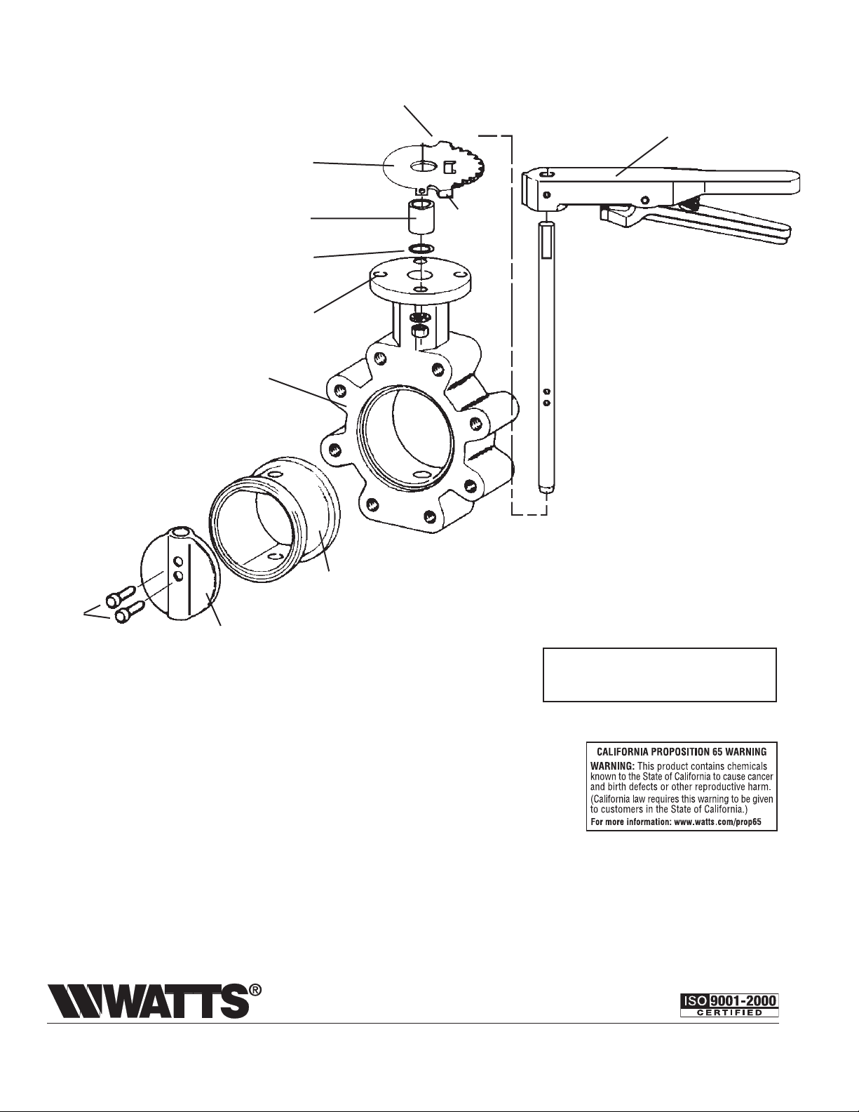
Latch Plate
See Note 2
Standard Handle
Bushing
Shaft Seal
Bonnet Slot
Body
Phenolic
Disc
Pins
2" to 4" - 1 Pin
Disc
Backed
Seat
5" and up - 2 Pins
Note 2: Standard handle must be eld mounted.
Note: Product information is subject to change without
notice and supersedes all previous publications.
Ta b
Assembled and tested in the U.S.A.
from domestic components and foreign
components produced by Watts China.
Limited Warranty: Watts Regulator Co. (the “Company”) warrants each product to be free from defects in material and workmanship under normal usage for a period of one year from the date of
original shipment. In the event of such defects within the warranty period, the Company will, at its option, replace or recondition the product without charge.
THE WARRANTY SET FORTH HEREIN IS GIVEN EXPRESSLY AND IS THE ONLY WARRANTY GIVEN BY THE COMPANY WITH RESPECT TO THE PRODUCT. THE COMPANY MAKES NO OTHER
WARRANTIES, EXPRESS OR IMPLIED. THE COMPANY HEREBY SPECIFICALLY DISCLAIMS ALL OTHER WARRANTIES, EXPRESS OR IMPLIED, INCLUDING BUT NOT LIMITED TO THE IMPLIED
WARRANTIES OF MERCHANTABILITY AND FITNESS FOR A PARTICULAR PURPOSE.
The remedy described in the first paragraph of this warranty shall constitute the sole and exclusive remedy for breach of warranty, and the Company shall not be responsible for any incidental, special
or consequential damages, including without limitation, lost profits or the cost of repairing or replacing other property which is damaged if this product does not work properly, other costs resulting
from labor charges, delays, vandalism, negligence, fouling caused by foreign material, damage from adverse water conditions, chemical, or any other circumstances over which the Company has no
control. This warranty shall be invalidated by any abuse, misuse, misapplication, improper installation or improper maintenance or alteration of the product.
Some States do not allow limitations on how long an implied warranty lasts, and some States do not allow the exclusion or limitation of incidental or consequential damages. Therefore the above
limitations may not apply to you. This Limited Warranty gives you specific legal rights, and you may have other rights that vary from State to State. You should consult applicable state laws to
determine your rights. SO FAR AS IS CONSISTENT WITH APPLICABLE STATE LAW, ANY IMPLIED WARRANTIES THAT MAY NOT BE DISCLAIMED, INCLUDING THE IMPLIED WARRANTIES OF
MERCHANTABILITY AND FITNESS FOR A PARTICULAR PURPOSE, ARE LIMITED IN DURATION TO ONE YEAR FROM THE DATE OF ORIGINAL SHIPMENT.
Water Safety & Flow Control Products
Canada: 5435 North Service Rd., Burlington, ONT. L7L 5H7; www.wattscanada.ca
USA: 815 Chestnut St., No. Andover, MA 01845-6098; www.watts.com
IS-DBF 0829 EDP#1910984 © Watts, 2008
 Loading...