

Watts Aerco BMK 750, Aerco BMK 2500, Aerco BMK 3000, Aerco BMK 5000, Aerco BMK 6000 Operation And Service Manual
...Page 1

Operation and Serv ice Manual
Other documents for this product include :
OMM-0137_D • GF-211 • 7/16/2019
Benchmark® Platinum Boilers
With Edge Controller
Natural Gas, Propane Gas and Dual Fuel
Modulating & Condensing Boilers
Models 750 through 6000
OMM-0136, GF-210 210 Installation and Startup Man ual
OMM-0138, GF-212 Reference Manual
OMM-0139, GF-213 Edge Controller Manual
TAG-0019, GF-2070 Boiler Application Guide
TAG-0022, GF-2050 Vent-Combustion Air Guide
TAG-0047, GF-2030 Benchmark Gas Guide
TAG-0048, GF-2060 Benchmark Power Guide
Applies to serial numbers:
G-19-0300 and above – B MK 750 – 3000
N-19-0100 and above – BMK 5000 & 6000
Page 2

Benchmark Platinum-Edge: Operation-Service Manual
CONTENTS
Table of Contents
FOREWORD ...................................................................................................... 5
SECTION 1: SAFETY PRECAUTIONS ................................................................... 9
1.1 WARNINGS & CAUTIONS ..................................................................................................................... 9
1.2 EMERGENC Y SHUT D OWN ................................................................................................................. 10
1.3 PROLONGED SHUTDOWN ................................................................................................................. 10
1.4 IMPORTANT – FOR MASSACHUSETTS INSTALLATIONS ............................................................... 11
SECTION 2: EDGE CONTROLLER OPERATION .................................................. 13
2.1 INTRODUCTION ................................................................................................................................... 13
2.2 LOGIN AND PASSWORD ENTRY ....................................................................................................... 14
SECTION 3: START SEQUENCE ........................................................................ 15
3.1 INTRODUCTION ................................................................................................................................... 15
3.2 START SEQUENCE ............................................................................................................................. 15
3.3 START/STOP LEVELS ......................................................................................................................... 23
3.4 START/STOP LEVELS – AIR/FUEL & ENERGY INPUT ..................................................................... 24
3.4.1 BMK 750/1000 Air/Fuel Valve Position and Energy Input .............................................................................. 24
3.4.2 BMK 1500 Air/Fuel Valve Position and Energy Input ...................................................................................... 25
3.4.3 BMK 2000 Air/Fuel Valve Position and Energy Input ...................................................................................... 26
3.4.4 BMK 2500 Air/Fuel Valve Position and Energy Input ...................................................................................... 27
3.4.5 BMK 3000 Air/Fuel Valve Position and Energy Input ...................................................................................... 28
3.4.6 Benchmark 5000 Air/Fuel Valve Position and Energy Input ........................................................................... 29
3.4.7 Benchmark 6000 Air/Fuel Valve Position and Energy Input ........................................................................... 30
SECTION 4: INITIAL START-UP ........................................................................ 31
4.1 INITIAL START-UP REQUIREMENTS ................................................................................................. 31
4.2 TOOLS & INSTRUMENTS FOR COMBUSTION CALIBRATION ........................................................ 32
4.2.1 Required Tools & Instrumentation ................................................................................................................. 32
4.2.2 Installing Gas Supply Manometer ................................................................................................................... 32
4.2.3 Accessing the Analyzer Probe Port ................................................................................................................. 35
4.3 FUEL TYPES AND COMBUSTION CALIBRATION ............................................................................. 36
4.4 COMBUSTION CALIBRATION ............................................................................................................. 36
4.4.1 NATURAL GAS Manual Combustion Calibration ............................................................................................. 37
4.4.2 PROPANE GAS COMBUSTION CALIBRATION .................................................................................................. 42
4.5 REASSEMBLY ...................................................................................................................................... 47
4.6 DUAL FUEL SWITCHOVER ................................................................................................................. 48
4.7 OVER-TEMPERATURE LIMIT SWITCHES ......................................................................................... 49
4.7.1 Adjusting the Automatic Reset Limit Switch Temperature ............................................................................ 49
4.7.2 Resetting the Manual Reset Limit Switch ....................................................................................................... 50
4.7.3 Changing the Readout Between Fahrenheit and Celsius ................................................................................ 50
SECTION 5: SAFETY DEVICE TESTING .............................................................. 51
5.1 TESTING OF SAFETY DEVICES ......................................................................................................... 51
5.2 LOW GAS PRESSURE TEST .............................................................................................................. 52
5.2.1 LOW GAS PRESSURE TEST: BMK 750 – 2500 ................................................................................................... 52
5.2.2 LOW GAS PRESSURE TEST: BMK 3000 – 6000 Only ........................................................................................ 54
5.3 HIGH GAS PRESSURE TEST ............................................................................................................. 57
5.3.1 HIGH GAS PRESSURE TEST: BMK 750 – 2500 .................................................................................................. 57
OMM-0137_D • GF-211 • 7/16/2019 Technical Support • (800) 526-0288 • Mon-Fri, 8 am - 5 pm EST Page 2 of 146
Page 3

Benchmark Platinum-Edge: Operation-Service Manual
CONTENTS
5.3.2 HIGH GAS PRESSURE TEST: BMK 3000 – 6000 Only ........................................................................................ 59
5.4 LOW WATER LEVEL FAULT TEST ..................................................................................................... 62
5.5 WATER TEMPERATURE FAULT TEST .............................................................................................. 63
5.6 INTERLOCK TESTS ............................................................................................................................. 64
5.6.1 Remote Interlock Test..................................................................................................................................... 64
5.6.2 Delayed Interlock Test .................................................................................................................................... 64
5.7 FLAME FAULT TEST ............................................................................................................................ 65
5.8 AIR FLOW FAULT TESTS - BLOWER PROOF & BLOCKED INLET SWITCHES .............................. 66
5.8.1 Blower Proof Switch Test ................................................................................................................................ 66
5.8.2 Blocked Inlet Switch Test ................................................................................................................................ 68
5.9 SSOV PROOF OF CLOSURE SWITCH CHECK ................................................................................. 69
5.10 PURGE SWITCH OPEN DURING PURGE ........................................................................................ 70
5.11 IGNITION SWITCH OPEN DURING IGNITION ................................................................................. 72
5.12 SAFETY PRESSURE RELIEF VALVE TEST ..................................................................................... 72
SECTION 6: STANDALONE MODES OF OPERATION ......................................... 73
6.1 OUTDOOR RESET MODE ................................................................................................................... 73
6.1.1 Outdoor Air Temperature Sensor Installation ................................................................................................ 73
6.1.2 Outdoor Reset Mode Startup ......................................................................................................................... 74
6.2 CONSTANT SETPOINT MODE ........................................................................................................... 75
6.3 REMOTE SETPOINT MODE ................................................................................................................ 75
6.4 DIRECT DRIVE MODES....................................................................................................................... 76
6.5 AERCO CONTROL SYSTEM (ACS) .................................................................................................... 77
6.6 COMBINATION CONTROL SYSTEM (CCS) ....................................................................................... 78
6.6.1 Combination Control System Field Wiring ...................................................................................................... 79
6.6.2 Combination Control System Setup and Startup ............................................................................................ 79
SECTION 7: BOILER SEQUENCING TECHNOLOGY ............................................ 81
7.1 INTRODUCTION ................................................................................................................................... 81
7.1.1 Installation Notes............................................................................................................................................ 82
7.2 BST QUICK START CHART ................................................................................................................ 82
7.3 BST IMPLEMENTATION INSTRUCTION ............................................................................................ 83
7.3.1 Option 1 Constant Setpoint: Direct Wired Header Sensor ............................................................................. 83
7.3.2 Option 2 Constant Setpoint: Modbus Wired Header Sensor .......................................................................... 85
7.3.3 Option 3 Outdoor Reset: Direct Wired Header Sensor & Direct Wired Outdoor Sensor ............................... 87
7.3.4 Option 4 Outdoor Reset: Modbus Header Sensor & Modbus Outdoor Sensor .............................................. 89
7.3.5 Option 5 Remote Setpoint: Direct Wired Header Sensor & 4-20ma Setpoint Drive ...................................... 91
7.3.6 Option 6 Remote Setpoint: Direct Wired Header Sensor & Modbus Setpoint Drive ..................................... 93
7.3.7 Option 7 Remote Setpoint: Modbus Header Sensor & 4-20ma Setpoint Drive ............................................. 95
7.3.8 Option 8 Remote Setpoint: MODBUS Header Sensor & MODBUS Setpoint Drive ......................................... 97
SECTION 8: MAINTENANCE ............................................................................ 99
8.1 MAINTENANCE SCHEDULE ............................................................................................................... 99
8.2 IGNITER-INJECTOR – BMK 750 - 3000 ............................................................................................ 100
8.3 PILOT IGNITION ROD – BMK 5000 & 6000 ...................................................................................... 102
8.4 FLAME DETECTOR ........................................................................................................................... 102
8.5 O2 SENSOR ........................................................................................................................................ 103
8.5.1 Air Eductor Air Pump Maintenance – BMK 5000 & 6000 ........................................................................... 104
8.6 SAFETY DEVIC E T ESTING ............................................................................................................... 105
8.7 BURNER INSPECTION ...................................................................................................................... 105
8.8 CONDENSATE DRAIN TRAP ............................................................................................................ 108
OMM-0137_D • GF-211 • 7/16/2019 Technical Support • (800) 526-0288 • Mon-Fri, 8 am - 5 pm EST Page 3 of 146
Page 4

Benchmark Platinum-Edge: Operation-Service Manual
CONTENTS
8.9 AIR FILTER CLEANING AND REPLACEMENT ................................................................................ 109
8.10 REFRACTORY REPLACEMENT – BMK 5000 & 6000 ONLY ......................................................................... 109
8.10.1 Rear Refractory Replacement .................................................................................................................... 110
8.10.2 Front Refractory Replacement .................................................................................................................. 112
8.11 SHUTTING BOILER DOWN FOR EXTENDED PERIOD ................................................................. 113
8.11.1 Benchmark 5000/6000 Long Term Blower Storage .................................................................................... 113
8.12 RETURNING THE BOILER TO SERVICE AFTER SHUTDOWN .................................................... 115
8.13 RECOMMENDED PERIODIC TESTING .......................................................................................... 116
8.14 RECOMMENDED SPARES ............................................................................................................. 118
SECTION 9: AERTRIM OPERATION ................................................................ 119
9.1 AERTRIM INTRODUCTION ............................................................................................................... 119
9.2 AERTRIM ACTI VATION ..................................................................................................................... 119
9.3 OPERATION DETAILS ....................................................................................................................... 120
9.4 AERTRIM O2 SENSOR AUTO CALIBRATION .................................................................................. 122
9.5 AERTRIM MENU VAL U ES AND DEFAULTS..................................................................................... 123
9.6 AERTRIM MAINTENANCE AND TROUBLESHOOTING ................................................................... 129
SECTION 10: TROUBLESHOOTING .................................................................. 131
10.1 INTRODUCTION ............................................................................................................................... 131
10.2 ADDITIONAL FAULTS WITHOUT SPECIFIC FAULT MESSAGES ................................................ 143
NOTES: .................................................................................................. 145
OMM-0137_D • GF-211 • 7/16/2019 Technical Support • (800) 526-0288 • Mon-Fri, 8 am - 5 pm EST Page 4 of 146
Page 5

Benchmark Platinum-Edge: Operation-Service Manual
INPUT RANGE (BTU/HR.)
OUTPUT RANGE (BTU/HR.)
FORWARD
FOREWORD
The AERCO Benchmark (BMK) 750 through 6000 natural gas and propane fueled boilers are
modulating and condensing units. They represent a true industry advance that meets the needs
of today's energy and environmental concerns. Designed for application in any closed loop
hydronic system, the Benchmark's modulating capability relates energy input directly to
fluctuating system loads. These BMK models provide extremely high efficiency operation and
are ideally suited for modern low temperature, as well as, conventional heating systems.
The Benchmark models operate within the following input and output ranges:
IMPORTANT!
Unless otherwise specified:
• All descriptions provided in this document apply to the Benchmark Platinum Series of boiler.
• All measurements apply to both natural gas and propane models, unless otherwise
specified.
Benchmark Boiler Intake and Output Ranges
MODEL
MINIMUM MAXIMUM MINIMUM MAXIMUM
BMK 750 50,000 (14.6 kW) 750,000 (220 kW) 47,750 (14 kW) 716,250 (210 kW)
BMK 1000 50,000 (14.6 kW) 1,000,000 (293 kW) 48,300 (14.15 kW) 968,000 (284 kW)
BMK 1500 75,000 (22 kW) 1,500,000 (440 kW) 64,500 (18.9 kW) 1,395,000 (409 kW)
BMK 2000 100,000 (29.3 kW) 2,000,000 (586 kW) 86,000 (25.2 kW) 1,860,000 (545 kW)
BMK 2500 167,000 (48.9 kW) 2,500,000 (732 kW) 144,000 (42.2 kW) 2,395,000 (702 kW)
BMK 3000 200,000 (58.6 kW) 3,000,000 (879 kW) 174,000 (51.0 kW) 2,874,000 (842 kW)
BMK 5000 400,000 (117 kW) 5,000,000 (1465 kW) 348,000 (102 kW) 4,750,000 (1392 kW)
BMK 6000 400,000 (117 kW) 6,000,000 (1758 kW) 348,000 (102 kW) 5,700,000 (1670 kW)
The output of the boiler is a function of the unit’s firing rate (valve position) and return water
temperature.
When installed and operated in accordance with this Instruction Manual, the BMK 750 – 2000
and 5000 & 6000 comply with the NOx emission standards outlined in: South Coast Air
Quality Management District (SCAQMD), Rule 1146.2. In addition, the BMK 2500 – 6000
comply with the Bay Area Air Quality Management District regulation 9, Rule 7.
Whether used in singular or modular arrangements, the BMK boilers offer the maximum venting
flexibility with minimum installation space requirements. These boilers are Category II and IV,
positive pressure appliances. Single and/or multiple breeched units are capable of operation in
the following vent configurations:
• Room Combustion Air:
o Vertical Discharge
o Horizontal Discharge
• Ducted Combustion Air:
o Vertical Discharge
o Horizontal Discharge
OMM-0137_D • GF-211 • 7/16/2019 Technical Support • (800) 526-0288 • Mon-Fri, 8 am - 5 pm EST Page 5 of 146
Page 6

Benchmark Platinum-Edge: Operation-Service Manual
Symbol rate, or simply the number of distinct symbol changes
British Thermal Unit. A unit of energy approximately equal to the
Double Block and Bleed, a gas trains containing 2 Safety Shutoff
A control system developed by AERCO and currently used in all
FORWARD
These boilers are capable of being vented utilizing Polypropylene and AL29-4C vent systems. In
addition, the BMK 750 & 1000 models are also approved for PVC and CPVC, vent systems
(excluding the state of Massachusetts).
The Benchmark's advanced electronics are available in several selectable modes of operation
offering the most efficient operating methods and energy management system integration.
AERCO Technical Terminology Meanings
TERMINOLOGY MEANING
A (Amp) Ampere
ACS AERCO Control System, AERCO’s boiler management systems
ADDR Address
AGND Anal og Ground
ALRM Alarm
ANSI American National Standards Institute,
ASME American Society of Mechanical Engineers
AUX Auxiliary
BAS
Baud Rate
Building Automation System, often used interchangeably with EMS
(see below)
(signaling events) transmitted per second. It is not equal to bits per
second, unless each symbol is 1 bit long.
BMK (Benchmark) AERCO’s Benchmark series boilers
BMS or BMS II AERCO Boiler Management Systems
BLDG (Bldg) Building
BST AERCO on-board Boiler Sequencing Technology
BTU
heat required to raise 1 pound (0.45 kg) of water 1°F (0.55 °C)
BTU/HR BTUs per Hour (1 BTU/hr = 0.29 W)
CCS Combination Control System
CFH Cubic Feet per Hour (1 CFH = 0.028 m3/hr)
CO Carbon Monoxide
COMM (Comm) Communication
Cal. Calibration
CNTL Control
CPU Central Processing Unit
DBB
Valves (SSOVs) and a solenoid operated vent valve.
DIP Dual In-Line Package, a type of switch
ECU Electronic Control Unit (O2 sensor)
Edge Controller
OMM-0137_D • GF-211 • 7/16/2019 Technical Support • (800) 526-0288 • Mon-Fri, 8 am - 5 pm EST Page 6 of 146
Benchmark Platinum boilers.
Page 7

Benchmark Platinum-Edge: Operation-Service Manual
EMS
Energy Management System; often used interchangeably with BAS
LN
Low Nitrogen Oxide
MA (mA)
Milliampere (1 thousandth of an ampere)
MAX (Max)
Maximum
MBH
1000 BTUs per Hour
duplex data transmission protocol developed by AEG
NO (N.O.)
Normally Open
NOx
Nitrogen Oxide
NPT
National Pipe Thread
O2
Oxygen
FORWARD
AERCO Technical Terminology Meanings
TERMINOLOGY MEANING
FM Factor y Mutual. Used to define boiler gas trains.
GF-xxxx Gas Fired (an AERCO document numbering system)
GND Ground
HDR Header
Hex Hexadecimal Number (0 – 9, A – F)
HP Horse Power
HX Heat Exchanger
Hz Hertz (Cycles Per Second)
I.D. Inside Diameter
IGN Ignition
IGST Board Ignition/Stepper Board, contained in Edge Controller
INTLK (INTL’K) Interlock
I/O Input/Output
I/O Box Input/Output (I/O) Box currently used on Benchmark boilers
IP Internet Protocol
ISO International Organization for Standardization
Lbs. Pounds (1 lb = 0.45 kg)
LED Light Emitting Diode
MIN (Min) Minimum
Modbus®
A serial, half-
Modicon
NC (N.C.) Normally Closed
O.D. Outside Diameter
OMM, O&M Operation and Maintenance Manual
onAER
AERCO’s on-line remote monitoring s y stem
PCB Printed Circuit Board
PMC Board Primary Micro-Contr oller (PMC) board, contained in the Edge
P/N Part Number
OMM-0137_D • GF-211 • 7/16/2019 Technical Support • (800) 526-0288 • Mon-Fri, 8 am - 5 pm EST Page 7 of 146
Page 8

Benchmark Platinum-Edge: Operation-Service Manual
POC
Proof of Closure
duplex (FDX) transmission of data based
SPDT
Single Pole Double Throw, a type of switch
SSOV
Safety Shut Off Valve
TEMP (Temp)
Temperature
prevent reflections that may cause invalid data in the
FORWARD
AERCO Technical Terminology Meanings
TERMINOLOGY MEANING
PPM Part s per Million
PSI Pounds per Square Inch (1 PSI = 6.89 kPa)
PTP Point-to-Point (usually over RS232 networks)
P&T Pressure and Temperature
ProtoNode Hardware interface between BAS and a boiler or water heater
PVC Poly Vinyl Chloride, a common synthetic plastic
PWM Pulse Width Modulation
REF (Ref) Reference
RES. Resistive
RS232
(or EIA-232)
RS485
(or EIA-485)
A standard for serial, full-
on the RS232 Standard
A standard for serial, half-duplex (HDX) transmission of data based
on the RS485 Standard
RTN (Rtn) Return
SETPT (Setpt) Setpoint Temperature
SHLD (Shld) Shield
A resistor placed at each end of a daisy-chain or multi-drop network
Terminating Resistor
in order to
communication
Tip-N-Tell A device that indicates if a package was tipped during shipping
UL A business that tests and validates products
VAC Volts, Alternating Current
VDC Volts, Direct Current
VFD Variable Frequency Drive
VPS Valve Proving System
W Watt
W.C. Water Column, a unit of pressure (1 W.C. = 249 Pa)
µA Micro amp (1 millionth of an ampere)
OMM-0137_D • GF-211 • 7/16/2019 Technical Support • (800) 526-0288 • Mon-Fri, 8 am - 5 pm EST Page 8 of 146
Page 9

Benchmark Platinum-Edge: Operation-Service Manual
SECTION 1: SAFETY PRECAUTIONS
SECTION 1: SAFETY PRECAUTIONS
1.1 WARNINGS & CAUTIONS
Installers and operating personnel MUST, at all times, observe all safety regulations. The
following warnings and cautions are general and must be given the same attention as specific
precautions included in these instructions. In addition to all the requirements included in this
AERCO Instruction Manual, the installation of units MUST conform with local building codes, or,
in the absence of local codes, ANSI Z223.1 (National Fuel Gas Code Publication No. NFPA-54)
for gas-fired boilers and ANSI/NFPASB for LP gas-fired boilers. W here applicable, the
equipment shall be installed in accordance with the current Installation Code for Gas Burning
Appliances and Equipment, CSA B149.1, and applicable Provincial regulations for the class;
which should be carefully followed in all cases. Authorities having jurisdiction should be
consulted before installations are made.
See section 1.4 for important information regarding installation of units within the
Commonwealth of Massachusetts.
IMPORTANT!
This manual is an integral part of the product and must be maintained in legible condition. It
must be given to the user by the installer and kept in a safe place for future reference.
WARNING!
• Do not use matches, candles, flames, or other sources of ignition to check for gas leaks.
• Fluids under pressure may cause injury to personnel or damage to equipment when
released. Be sure to shut off all incoming and outgoing water shutoff valves. Carefully
decrease all trapped pressures to zero before performing maintenance.
• Before attempting to perform any maintenance on the unit, shut off all g as and electrical
inputs to the unit.
• The exhaust vent pipe of the unit operates under a positive pressure and therefore must
be completely sealed to prevent leakage of combustion products into living spaces.
• Electrical voltages up to 120 VAC (BMK 750 – 2000) and 208 or 460 VAC (BMK
2500/3000) or 208, 460 or 575 VAC (BMK 5000 & 6000) and 24 vo lts AC may be used
in this equipment. Therefore the cover on the unit’s power box (located behind the front
panel door) must be installed at all times, except during maintenance and servicing.
• A single-pole (120 VAC units) or three-pole (220 VAC and higher units) switch must be
installed on the electrical supply line of the unit. The switch must be installed in an easily
accessible position to quickly and safely disconnect electrical service. Do not affix switch
to unit sheet metal enclosures.
CAUTION!
• Many soaps used for gas pipe leak testing are corrosive to metals. The piping must be
rinsed thoroughly with clean water after leak checks have been completed.
• DO NOT use this boiler if any part has been under water. Call a qualified service
technician to inspect and replace any part that has been under water.
OMM-0137_D • GF-211 • 7/16/2019 Technical Support • (800) 526-0288 • Mon-Fri, 8 am - 5 pm EST Page 9 of 146
Page 10
Benchmark Platinum-Edge: Operation-Service Manual
VALVE
CLOSED
SECTION 1: SAFETY PRECAUTIONS
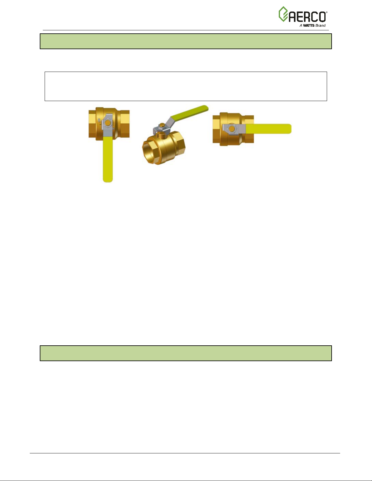
1.2 EMERGENCY SHUTDOWN
If overheating occurs or the gas supply fails to shut off, close the manual shutoff valve (Figure 1-
1) located external to the unit.
NOTE:
The Installer must identify and indicate the location of the emergency shutdown manual gas
valve to operating personnel.
VALVE
OPEN
Figure 1-1: External Manual Gas Shutoff Valve
In addition, to ensure safety an emergency shutdown procedure that addresses the following
points should be designed and implement at the site:
• For automatically operated unattended boilers located in a boiler room, provide a
manually operated remote shutdown switch or circuit breaker located just inside or
outside each boiler room door. Design the system so activation of the emergency
shutdown switch or circuit breaker will immediately shut off the fuel supply to the unit(s).
• For automatically operated unattended boilers in a location other than a boiler room,
provide a manually operated remote shutdown switch or circuit breaker marked for easy
identification at a location readily accessible in the event of boiler mis-operation.
• Design the system so activation of the emergency shutdown switch or circuit breaker will
immediately shut off the fuel.
• For boilers monitored and/or operated from a continuously occupied control room,
provide an emergency shutdown switch in the control room that is hard-wired to
immediately shut off the fuel upon activation.
1.3 PROLONGED SHUTDOWN
If there is an emergency, turn off the electrical power supply to the boiler and close the manual
gas valve located upstream from the unit. The installer must identify the emergency shut-off
device.
If the unit is being shut down for an extended period of time, such as a year or more, complete
the instructions in Section 8.11: Shutting Boiler Down For Extended Period.
When returning a unit to service after a prolonged shutdown, it is recommended that the
instructions in Section 4: Initial Startup Procedures and Section 5: Safety Device Testing be
performed to verify that all system-operating parameters are correct.
.
OMM-0137_D • GF-211 • 7/16/2019 Technical Support • (800) 526-0288 • Mon-Fri, 8 am - 5 pm EST Page 10 of 146
Page 11

Benchmark Platinum-Edge: Operation-Service Manual
Requirements For Massachusetts Installations
Boiler Installations within the Commonwealth of Massachusetts must conform to the
(a) For all side wall horizontally vented gas fueled equipment installed in every dwelling,
alled on each additional level of the dwelling,
be the responsibility of the property owner to secure the services of qualified licensed
the above requirements; provided, however, that during said thirty (30) day period, a
Each carbon monoxide detector as
accordance with the above provisions shall comply with NFPA 720 and be
VENT DIRECTLY BELOW. KEEP CLEAR OF ALL OBSTRUCTIONS". (Continued)
SECTION 1: SAFETY PRECAUTIONS
1.4 IMPORTANT – FOR MASSACHUSETTS INSTALLATIONS
following requirements:
• Boiler must be installed by a plumber or a gas fitter who is licensed within the
Commonwealth of Massachusetts.
• Prior to unit operation, the complete gas train and all connections must be leak
tested using a non-corrosive soap.
• The vent termination must be located a minimum of 4 feet above grade level. If
side-wall venting is used, the installation must conform to the following
requirements extracted from 248 CMR 5.08 (2):
building or structure used in whole or in part for residential purposes, including those owned or
operated by the Commonwealth and where the side wall exhaust vent termination is less than
seven (7) feet above finished grade in the area of the venting, including but not limited to decks
and porches, the following requirements shall be satisfied:
1. INSTALLATION OF CARBON MONOXIDE DETECTORS: At the time of installation of the
side wall horizontal vented gas fueled equipment, the installing plumber or gasfitter shall
observe that a hard wired carbon monoxide detector with an alarm and battery back-up is
installed on the floor level where the gas equipment is to be installed. In addition, the
installing plumber or gasfitter shall observe that a battery operated or hard wired carbon
monoxide detector with an alarm is inst
building or structure served by the side wall horizontal vented gas fueled equipment. It shall
professionals for the installation of hard wired carbon monoxide detectors.
a. In the event that the side wall horizontally vented gas fueled equipment is installed in a
crawl space or an attic, the hard wired carbon monoxide detector with alarm and battery
back-up may be installed on the next adjacent floor level.
b. In the event that the requirements of this subdivision can not be met at the time of
completion of installation, the owner shall have a period of thirty (30) days to comply with
battery operated carbon monoxide detector with an alarm shall be installed.
2. APPROVED CARBON MONOXIDE DETECTORS:
required in
ANSI/UL 2034 listed and IAS certified.
3. SIGNAGE: A metal or plastic identification plate shall be permanently mounted to the
exterior of the building at a minimum height of eight (8) feet above grade directly in line
with the exhaust vent terminal for the horizontally vented gas fueled heating appliance or
equipment. The sign shall read, in print size no less than one-half (1/2) inch in size, "GAS
OMM-0137_D • GF-211 • 7/16/2019 Technical Support • (800) 526-0288 • Mon-Fri, 8 am - 5 pm EST Page 11 of 146
Page 12

Benchmark Platinum-Edge: Operation-Service Manual
Requirements For Massachusetts Installations
observes carbon monoxide detectors and signage installed in accordance with the
venting system design or venting system components with the equipment, the instructions
When the manufacturer of a Product Approved side wall horizontally vented gas fueled
nd the
SECTION 1: SAFETY PRECAUTIONS
4. INSPECTION: The state or local gas inspector of the side wall horizontally vented gas
fueled equipment shall not approve the installation unless, upon inspection, the inspector
provisions of 248 CMR 5.08(2)(a)1 through 4.
(b) EXEMPTIONS: The following equipment is exempt from 248 CMR 5.08(2)(a)1 through 4:
1. The equipment listed in Section 10 entitled "Equipment Not Required To Be Vented" in
the most current edition of NFPA 54 as adopted by the Board; and
2. Product Approved side wall horizontally vented gas fueled equipment installed in a
room or structure separate from the dwelling, building or structure used in whole or in
part for residential purposes.
(c) MANUFACTURER REQUIREMENTS - GAS EQUIPMENT VENTING SYSTEM PROVIDED. When
the manufacturer of Product Approved side wall horizontally vented gas equipment provides a
provided by the manufacturer for installation of the equipment and the venting system shall
include:
1. Detailed instructions for the installation of the venting system design or the venting
system components; and
2. A complete parts list for the venting system design or venting system.
(d) MANUFACTURER REQUIREMENTS - GAS EQUIPMENT VENTING SYSTEM NOT PROVIDED.
equipment does not provide the parts for venting the flue gases, but identifies "special venting
systems", the following requirements shall be satisfied by the manufacturer:
1. The referenced "special venting system" instructions shall be included with the appliance
or equipment installation instructions; and
2. The "special venting systems" shall be Product Approved by the Board, a
instructions for that system shall include a parts list and detailed installation instructions.
(e) A copy of all installation instructions for all Product Approved side wall horizontally vented
gas fueled equipment, all venting instructions, all parts lists for venting instructions, and/or all
venting design instructions shall remain with the appliance or equipment at the completion of
the installation.
……………….[End of Extracted Information From 248 CMR 5.08 (2)]…………………
OMM-0137_D • GF-211 • 7/16/2019 Technical Support • (800) 526-0288 • Mon-Fri, 8 am - 5 pm EST Page 12 of 146
Page 13
Benchmark Platinum-Edge: Operation-Service Manual
temperature
temperature
1 2 3 6 7
10
11 4 5
9
8
SECTION 2: OPERATION
SECTION 2: EDGE CONTROLLER OPERATION
2.1 INTRODUCTION
This section provides a brief outline of how to gain access to Benchmark Boiler’s Edge
Controller functionality. Full instructions for using the Edge Controller to setup, configure and
operate a Benchmark Boiler are included in the Edge Controller Manual.
NOTE: The Edge Controller Manual is document number OMM-0139, GF-213.
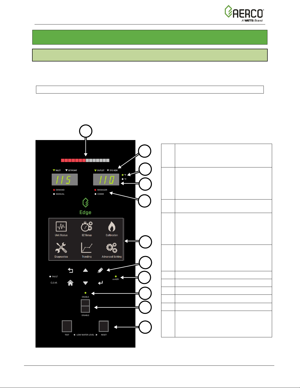
The Edge Controller is shown below. This panel contains all of the controls, indicators and
displays necessary to operate, adjust and troubleshoot the boiler.
The Edge Controller’s front panel consists of a touchscreen display along with a variety of
indicators and buttons.
Multi-Function Bar, shows either:
1
• Fire Rate
• Valve Position
Parameter Indicator for both temperature
read-outs:
2
• LEFT: Inlet or Setpoint temperature
• RIGHT: Outlet or System Header
Temperature scale indicator: Fahrenheit
3
or Celsius
Configurable temperature read-outs (2):
• LEFT: Inlet or Setpoint
4
• RIGHT: Outlet or System Header
Operation Mode Indicators (2):
• LEFT: Demand or Manual
5
• RIGHT: Manager or Client (BST
6 Edge Controller Touchscreen
7 Soft Keys
8 onAER Indicator Light
Ready Light
9
10 Enable/Disable Switch
Low Water Level Buttons (2):
• TEST: Initiates Low Water test
11
• RESET: Resets unit after Low Water
temperature
only)
test
Figure 2-1 Edge Controller Front Panel
OMM-0137_D • GF-211 • 7/16/2019 Technical Support • (800) 526-0288 • Mon-Fri, 8 am - 5 pm EST Page 13 of 146
Page 14
Benchmark Platinum-Edge: Operation-Service Manual
SECTION 2: OPERATION
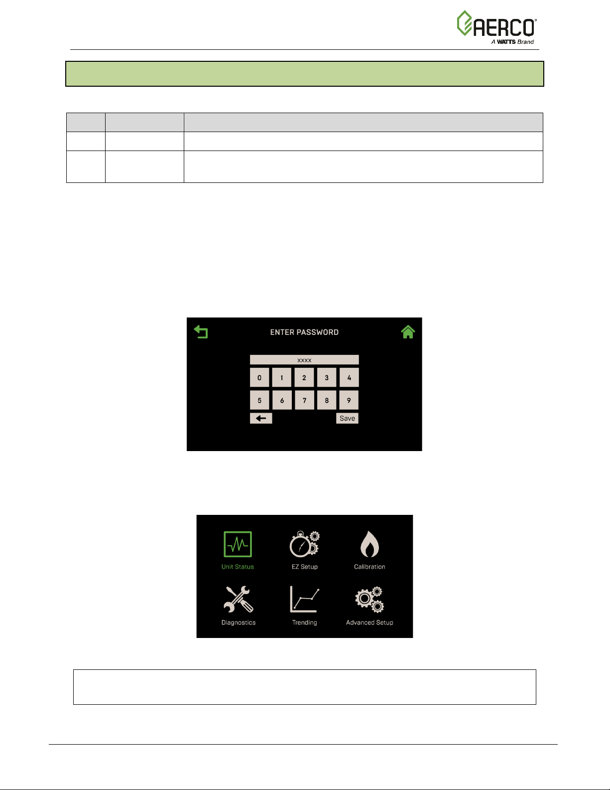
2.2 Login and Password Entry
The Edge Controller has multiple levels of password protection.
Level Password Description
1 No password The default. Many parameters are visible but “Read Only.”
2 159
A higher-level password is reserved AERCO Master Technicians (AMT). It is distributed on an
individual basis.
To enter a password:
1. On the Edge Controller, go to
Password screen appears.
2. Use the number keypad to enter the password (each number appears as a X), then pr es s
Save. You will have access to the functionality associated with the level of the password
entered.
Allows routine maintenance to be performed. Appropriate for AERCO
Trained technicians (ATT).
Main Menu Advanced Setup Access. The Enter
Figure 2.2: Enter Password Screen
3. Once you have successfully logged into the system, the Main Menu appears. All Edge
functionality is accessed through one of the six Main Menu items.
Figure 2-3: Edge Controller Main Menu
NOTE:
Full instruct ions for using the Edge Controller are in the Edge Controller Manual (GF-213).
OMM-0137_D • GF-211 • 7/16/2019 Technical Support • (800) 526-0288 • Mon-Fri, 8 am - 5 pm EST Page 14 of 146
Page 15

Benchmark Platinum-Edge: Operation-Service Manual
SECTION 3 - START SEQUENCE
SECTION 3: START SEQUENCE
3.1 INTRODUCTION
The information in this section provides a guide to starting the Benchmark Boiler using the Edge
Controller. It is imperative that the initial startup of this unit be performed by factory trained
personnel. Operation prior to initial startup by factory trained personnel may void the equipment
warranty. In addition, the following WARNINGS and CAUTIONS must be observed at all times.
WARNING!
• All of the installation procedures in Section 2: Installation of the Benchmark Platinum-
Edge: INSTALLATION Manual (GF-210) must be completed before the initial start-up of
the unit.
• Electrical voltages up to 120 VAC (BMK 750 – 2000) and 208 or 460 VAC (BMK
2500/3000) or 208, 460 or 575 VAC (BMK 5000 & 6000) and 24 vo lts AC may be used
in this equipment. It must be serviced only by factory certified service technicians.
• Do not attempt to dry fire the unit. Starting the unit without a full water level can
seriously damage the unit and may result in injury to personnel or property damage. This
situation will void any warranty.
• Initial startup of the unit must be be performed by AERCO factory trained personnel.
Operation prior to initial startup by factory trained personnel may void the equipment
warranty. In addition, the following WARNINGS and CAUTIONS must be observed at all
times.
3.2 START SEQUENCE
When the Edge Controller Enable/Disable switch is set to t he Enable position, it checks all prepurge safety switches to ensure they are closed. These switches include:
• High Water Temperature switch
• High Gas Pressure switch
• Low Gas Pressure switch
• Low Water Level switch
• Safety Shut-Off Valve (SSOV) Proof of Closure (POC) switch
NOTE:
The Blocked Inl et and downstream B lower Proof switches are not checked prior to starting
the pre-purge.
If all of the above switches are closed, the READY light (above the Enable/Disable switch) will
light when the switch is in the Enable position and the unit will be in the STANDBY mode.
NOTE:
If any of the Pre-Purge safety device switches are open, or the required conditions are not
observed throughout the start sequence, appropriate fault messages will be displayed.
When there is a demand for heat, the following events occur:
OMM-0137_D • GF-211 • 7/16/2019 Technical Support • (800) 526-0288 • Mon-Fri, 8 am - 5 pm EST Page 15 of 146
Page 16

Benchmark Platinum-Edge: Operation-Service Manual
SSOV
NATURAL
GAS INLET
NATURAL
GAS INLET
SECTION 3 - START SEQUENCE
Start Sequence
1. The Controller’s red DEMAND LED status indicator will light.
2. The unit checks all five pre-purge safety switches listed at the beginning of this section.
The Edge Controller’s ignition sequence screen walks you through the ignition screens and
demonstrates (or highlights) which switches are not met. SSOV locations are shown in
Figure 3-1a thro ugh 3-1d.
TO AIR/FUEL
VALVE
MANUAL
SHUT-OFF VALVE
LOW GAS
PRESSURE
SWITCH
Figure 3-1a: BMK 750 & 1000 SSOV Location (P/N 22322 shown)
TO
AIR/FUEL
MANUAL
SHUT-OFF
VALVE
VALVE
SSOV
HIGH GAS
PRESSURE
SWITCH
LOW GAS
PRESSURE
SWITCH
Figure 3-1b: BMK 1500 & 2000 SSOV Location (P/N 22314 shown)
OMM-0137_D • GF-211 • 7/16/2019 Technical Support • (800) 526-0288 • Mon-Fri, 8 am - 5 pm EST Page 16 of 146
Page 17

Benchmark Platinum-Edge: Operation-Service Manual
VALVE
NATURAL
GAS INLET
LOW GAS
SWITCH
NATURAL
GAS INLET
SECTION 3 - START SEQUENCE
Start Sequence
SSOV
TO
AIR/FUEL
MANUAL
SHUT-OFF
VALVE
VALVE
LOW GAS
PRESSURE
SWITCH
Figure 3-1c: BMK 2500: SSOV Location (P/N 22318 shown)
TO
AIR/FUEL
MANUAL
SHUT-OFF VALVE
HIGH GAS PRESSURE
SWITCH
Figure 3-1d: BMK 3000: SSOV L o cation (P/N 22310 shown)
SSOV
PRESSURE
OMM-0137_D • GF-211 • 7/16/2019 Technical Support • (800) 526-0288 • Mon-Fri, 8 am - 5 pm EST Page 17 of 146
Page 18

Benchmark Platinum-Edge: Operation-Service Manual
STEPPER MOT OR
100
UPSTREAM
TO AIR/FUEL
GAS INLET
MANUAL SHUT-
DOWNSTREAM
HIGH GAS
UPSTREAM LOW GAS
SECTION 3 - START SEQUENCE
Start Sequence
SSOV
SSOV WITH
VALVE
OFF VALVE
POC
- BMK 6000: 10.5” W.C., 2.6 kPa
- BMK 5000: 11.0” W.C., 2.7 kPa
PRESSURE SWITCH
PRESSURE SWITCH
- BMK 6000: 8.5” W.C., 2.1 kPa
- BMK 5000: 8.0” W.C., 2.0 kPa
Figure 3-1e: BMK 5000-6000: SSOV Location
3. The Auxiliary Delay occurs for a configurable length of time and the Delayed Interlocks are
closed.
4. Once all required safety device switches are closed, a purge cycle is initiated and the
following events occur:
a. The Blower relay energizes and turns on the blower.
b. The Air/Fuel Valve rotates to the full-open purge position and closes purge position
switch. The dial on the Air/Fuel Valve (Figure 3-2a and 3-2b) will read 100 to indicate
that it is full-open (100%).
c. The Fire Rate bargraph on the Controller’s front face shows 100%.
AIR INLET
OMM-0137_D • GF-211 • 7/16/2019 Technical Support • (800) 526-0288 • Mon-Fri, 8 am - 5 pm EST Page 18 of 146
Figure 3-2a: BMK 750 & 1000 Air/Fuel Valve in Purge Position
TO
BLOWER
Page 19

Benchmark Platinum-Edge: Operation-Service Manual
TO BLOWER
STEPPER
MOTOR
AIR IN
SECTION 3 - START SEQUENCE
Start Sequence
PURGE
VALVE POSITION
DIAL AT 100%
Figure 3-2b: BMK 1500 – 6000 Air/Fuel Valve In Purge Position
5. Next, the Blower Proof and Blocked Inlet switches close (Figure 3-4a and 3-4b). On the
Ignition Sequence screen the Purging indicator turns grey while purging is underway
(Figure 3-3) and Purge Timer displays the purge cycle’s elapsed time in seconds.
Figure 3-3: Ignition Sequence Screen – Purging
BLOWER PROOF SWITCH
BLOCKED INLET SWITCH
Figure 3-4a: BMK 750 & 1000 Blower Proof Switch
OMM-0137_D • GF-211 • 7/16/2019 Technical Support • (800) 526-0288 • Mon-Fri, 8 am - 5 pm EST Page 19 of 146
Page 20

Benchmark Platinum-Edge: Operation-Service Manual
fire (Ignition) position and closes the ignition
cycle turns on the
the Ignition
AIR/FUEL VALVE
OUTLET TO BLOWER
BLOWER
SWITCH
TRAIN
SECTION 3 - START SEQUENCE
Start Sequence
PROOF
AIR/FUEL VALVE
INLET FROM GAS
BLOCKED
INLET
SWITCH
Figure 3-4b: BMK 1500 – 6000 Blower Proof Switch
6. Upon completion of the purge cycle, the Controller initiates an ignition cycle and the
following events occur:
a) The Air/Fuel Valve rotates to the low-
switch. The Dial on the Air/Fuel Valve (Figure 3-5) will read between 25 and 35 to
indicate that the valve is in the low fire position.
b) The Spark Cleaning cycle begins (default duration = 7 sec.) and the Ignition Sequence
screen’s Spark Cleaning indicator (Figure 3-3) turns grey. This
ignition transformer to produce a spark (with no gas flowing) to remove moisture and
carbon buildup from the spark element. For the duration of this cycle, the Controller
displays the Cleaning Igniter status message.
c) Following the Spark Cleaning cycle, power is applied to the gas S afety Shut -off Val ve
(SSOV). When the SSOV indicates the Gas Valve is OPEN (POC) and
Sequence screen’s Ignition indicator (Figure 3-3) turns grey.
d) If no spark is present 3 seconds into the ignition trial, the Controller aborts th e Igni tion
Cycle and shuts down the boiler. Refer to Section 10: Troubleshooting in this g uide for
guidance if this occurs.
OMM-0137_D • GF-211 • 7/16/2019 Technical Support • (800) 526-0288 • Mon-Fri, 8 am - 5 pm EST Page 20 of 146
Page 21

Benchmark Platinum-Edge: Operation-Service Manual
TO BLOWER
AIR IN
25% to 35%
STEPPER
MOTOR
SECTION 3 - START SEQUENCE
Start Sequence
IGNITION
VALVE POSITIO N
DIAL AT
Figure 3-5: Air/Fuel Valve In Ignition Position
7. Up to 4 seconds are allowed for ignition to be detected. The ignition circuit is turned off
one second after flame is detected.
8. After 2 seconds of continuous flame, the flame strength is indicated. After 5 seconds, the
Unit Status screen appears.
9. With the unit firing properly, it will be controlled by the temperature control circuitry. The
boiler’s fire rate or valve position (depending on which was chosen in Section 6.2.2: Front
Panel Configuration of the Edge Controller Manual) will continuously display on the
Controller’s bargraph.
10. Once the demand for heat has been satisfied, the Edge Controller will turn off the SSOV
gas valve. The blower relay will be deactivated and the Air/Fuel Valve wil l be closed.
Standby is displayed.
OMM-0137_D • GF-211 • 7/16/2019 Technical Support • (800) 526-0288 • Mon-Fri, 8 am - 5 pm EST Page 21 of 146
Page 22

Benchmark Platinum-Edge: Operation-Service Manual
Operating State
Pre-purge
PFEP
MFEP
Standby
T = 0
T = 30
T = 37
T = 44
Run
Component
PFEP
MFEP
C-More Controller
Scanner Power
Ignition Power
SSOV Power
Pilot Valve Closed
Pilot Valve Open
Ignition Transformer Off
Ignition Transformer On
UV Scanner Powered
UV Scanner "Ignored"
UV Scanner In Use
Relay 1 Coil
Relay 1 C-NC
Relay 1 C-NO
Relay 2 Coil Power from R1
Relay 2 Coil Power from SKP 15 POC
Relay 2 C-NC
Relay 2 C-NO
SKP15 Power from R1 Contacts
SKP15 Power from R2 contact and POC
C-NO
SKP15 Proof of Closure C-NC
SKP15 Proof of Closure C-NO
SKP25
Power through R1
Power through R2 and AUX
Proof of Closure C-NC
Proof of Closure C-NO
SECTION 3 - START SEQUENCE
BMK 5000 & 6000 Function Timing Chart For Proved Pilot Control System
OMM-0137_D • GF-211 • 7/16/2019 Technical Support • (800) 526-0288 • Mon-Fri, 8 am - 5 pm EST Page 22 of 146
Page 23

Benchmark Platinum-Edge: Operation-Service Manual
TABLE 3-1a: Start/Stop Levels – NATURAL GAS
Level:
Level:
Position
TABLE 3-1b: Start/Stop Levels – PROPANE GAS
750
1000
1500
2000
2500
3000
5000
6000
Level:
Level:
SECTION 3 - START SEQUENCE
3.3 START/STOP LEVELS
The start and stop levels are the Air/Fuel Valve positions (% open) that start and stop the unit,
based on load. These levels are Factory preset as follows:
Start
Stop
Ignition
Start
Stop
Ignition
Position
BMK
750
22% 22% 20% 24% 24% 20% 24% 24%
18% 18% 16% 18% 16% 14% 18% 18%
35% 35% 29% 29% 29% 29% 35% 50%
BMK
22% 22% 20% 24% 26% 22% 24% 24%
18% 18% 16% 18% 18% 14% 18% 18%
35% 35% 29% 29% 29% 29% 35% 50%
BMK
1000
BMK
BMK
1500
BMK
BMK
2000
BMK
BMK
2500
BMK
BMK
3000
BMK
BMK
5000
BMK
BMK
6000
BMK
Normally, these settings do not require adjustment.
Note that the energy input of the boiler is not linearly related to the Air/Fuel Valve position.
OMM-0137_D • GF-211 • 7/16/2019 Technical Support • (800) 526-0288 • Mon-Fri, 8 am - 5 pm EST Page 23 of 146
Page 24

Benchmark Platinum-Edge: Operation-Service Manual
TABLE 3-2a: BMK 750/1000 Air/Fuel Valve Position – NATURAL GAS
CAPACITY)
BMK 750
BMK 1000
BMK 750
BMK 1000
0% 0 0
0
0
10% 0 0
0
0
18% (Stop Level)
50,000 (14.7 kW)
50,000 (14.7 kW)
6.7%
5%
20%
52,000 (15.2 kW)
54,000 (15.8 kW)
6.9%
5.4%
30%
108,000 (31.7 kW)
140,000 (41.0 kW)
14%
14%
40%
246,000 (72.1 kW)
297,000 (87.0 kW)
33%
30%
50%
369,000 (108.1 kW)
443,000 (126.9 kW)
49%
44%
60%
465,000 (136.3 kW)
564,000 (165.3 kW)
62%
56%
70%
554,000 (162.4 kW)
660,000 (193.4 kW)
74%
66%
80%
637,000 (186.7 kW)
789,000 (231.2 kW)
85%
79%
90%
733,000 (214.8 kW)
933,000 (273.4 kW)
98%
93%
100%
750,000 (219.8 kW)
1,000,000 (293.1 kW)
100%
100%
TABLE 3-2b: BMK 750/1000 Air/Fuel Valve Position – PROPANE GAS
BMK 750
BMK 1000
BMK 750
BMK 1000
0% 0 0
0
0
10% 0 0
0
0
18% (Stop Level)
50,000 (14.7 kW
50,000 (14.7 kW
6.7%
5.0%
20%
71,000 (20.8 kW)
71,000 (20.8 kW)
9.5%
7.1%
30%
128,000 (37.5 kW)
181,000 (53.0 kW)
17%
18%
40%
373,000 (109.3 kW)
400,000 (117.2 kW)
50%
40%
50%
508,000 (148.9 kW)
562,000 (164.7 kW)
68%
56%
60%
565,000 (165.6 kW)
703,000 (206.0 kW)
75%
70%
70%
621,000 (182.0 kW)
791,000 (231.8 kW)
83%
79%
80%
660,000 (193.4 kW)
865,000 (253.5 kW)
88%
87%
90%
723,000 (211.9 kW)
963,000 (282.2 kW)
96%
96%
100%
750,000 (219.8 kW)
1,000,000 (293.1 kW)
100%
100%
SECTION 3 - START SEQUENCE
3.4 START/STOP LEVELS – AIR/FUEL & ENERGY INPUT
The Tables below show the relationship between the energy input and Air/Fuel Valve position
for the BMK models covered in this document.
3.4.1 BMK 750/1000 Air/Fuel Valve Position and Energy Input
AIR/FUEL VALVE
POSITION (%
OPEN)
Air/Fuel Valve
Position (%
Open)
ENERGY INPUT
(BTU/HR)
Energy Input
(BTU/Hr)
BOILER ENERGY
INPUT (% OF FULL
Boiler Energy Input
(% of Full Capacity)
OMM-0137_D • GF-211 • 7/16/2019 Technical Support • (800) 526-0288 • Mon-Fri, 8 am - 5 pm EST Page 24 of 146
Page 25

Benchmark Platinum-Edge: Operation-Service Manual
TABLE 3-3a: BMK 1500 Air/Fuel Valve Position – NATURAL GAS
AIR/FUEL VALVE POSITION
(% OPEN)
ENERGY INPUT
(BTU/HR)
BOILER ENERGY INPUT
(% OF FULL CAPACITY)
16% (Stop Level)
75,000 (22.3 kW)
5.0%
20%
127,000 (37.2 kW)
8.5%
30%
366,000 (107.2 kW)
24.4%
40%
629,000 (184.3 kW)
41.9%
50%
822,000 (240.9 kW)
54.7%
60%
977,000 (286.2 kW)
65.0%
70%
1,119,000 (327.9 kW)
74.5%
80%
1,255,000 (367.7 kW)
83.5%
90%
1,396,000 (409.0 kW)
92.9%
100%
1,502,000 (440.1 kW)
100%
TABLE 3-3b: BMK 1500 Air/Fuel Valve Position – PROPANE GAS
AIR/FUEL VALVE POSITION
(% OPEN)
ENERGY INPUT
(BTU/HR)
BOILER ENERGY INPUT
(% OF FULL CAPACITY)
18% (Stop Level)
75,000
5.0%
20%
93,700
6.2%
30%
254,000
16.9%
40%
505,000
33.7%
50%
680,000
45.3%
60%
807,000
53.8%
70%
947,000
63.1%
80%
1,157,000
77.1%
90%
1,379,000
91.9%
100%
1,503,000
100%
SECTION 3 - START SEQUENCE
3.4.2 BMK 1500 Air/Fuel Valve Position and Energy Input
OMM-0137_D • GF-211 • 7/16/2019 Technical Support • (800) 526-0288 • Mon-Fri, 8 am - 5 pm EST Page 25 of 146
Page 26

Benchmark Platinum-Edge: Operation-Service Manual
TABLE 3-4a: BMK 2000 Air/Fuel Valve Position – NATURAL GAS
AIR/FUEL VALVE POSITION
(% OPEN)
ENERGY INPUT
(BTU/HR)
BOILER ENERGY INPUT
(% OF FULL CAPACITY)
18% (Stop Level)
100,000 (29.3 kW)
5.7%
20%
143,000 (41.9 kW)
11%
30%
388,000 (113.7 kW)
23%
40%
759,000 (222.4 kW)
37%
50%
1,069,000 (313.2 kW)
51%
60%
1,283,000 (375.9 kW)
61%
70%
1,476,000 (432.5 kW)
74%
80%
1,675,000 (490.1 kW)
83%
90%
1,833,000 (537.1 kW)
93%
100%
2,000,000 (586.0 kW)
100%
TABLE 3-4b: BMK 2000 Air/Fuel Valve Position – PROPANE GAS
AIR/FUEL VALVE POSITION
(% OPEN)
ENERGY INPUT
(BTU/HR)
BOILER ENERGY INPUT
(% OF FULL CAPACITY)
18% (Stop Level)
100,000
5.0%
20%
126,600
6.3%
30%
363,000
18.2%
40%
677,000
33.9%
50%
898,000
44.9%
60%
1,070,000
53.5%
70%
1,242,000
62.1%
80%
1,523,000
76.2%
90%
1,845,000
92.3%
100%
2,000,000
100%
SECTION 3 - START SEQUENCE
3.4.3 BMK 2000 Air/Fuel Valve Position and Energy Input
OMM-0137_D • GF-211 • 7/16/2019 Technical Support • (800) 526-0288 • Mon-Fri, 8 am - 5 pm EST Page 26 of 146
Page 27

Benchmark Platinum-Edge: Operation-Service Manual
TABLE 3-5a: BMK 2500 Air/Fuel Valve Position – NATURAL GAS, Single Fuel
AIR/FUEL VALVE POSITION
(% OPEN)
ENERGY INPUT
(BTU/HR)
BOILER ENERGY INPUT
(% OF FULL CAPACITY)
16% (Stop Level)
167,000 (48.9 kW)
6.7%
30%
430,000 (126.0 kW)
17%
40%
770,000 (225.7 kW)
31%
50%
1,070,000 (313.6 kW)
43%
60%
1,440,000 (422.0 kW)
58%
70%
1,815,000 (531.9 kW)
73%
80%
2,030,000 (594.9 kW)
81%
90%
2,300,000 (674.1 kW)
92%
100%
2,500,000 (732.7 kW)
100%
TABLE 3-5b: BMK 2500 Air/Fuel Valve Position – PROPANE GAS
AIR/FUEL VALVE POSITION
(% OPEN)
ENERGY INPUT
(BTU/HR)
BOILER ENERGY INPUT
(% OF FULL CAPACITY)
18% (Stop Level)
155,000
6.2%
30%
400,000
16%
40%
808,000
32%
50%
1,055,000
42%
60%
1,330,000
53%
70%
1,671,000
67%
80%
1,998,000
80%
90%
2,280,000
91%
100%
2,500,000
100%
SECTION 3 - START SEQUENCE
3.4.4 BMK 2500 Air/Fuel Valve Position and Energy Input
OMM-0137_D • GF-211 • 7/16/2019 Technical Support • (800) 526-0288 • Mon-Fri, 8 am - 5 pm EST Page 27 of 146
Page 28

Benchmark Platinum-Edge: Operation-Service Manual
TABLE 3-6a: BMK 3000 Air/Fuel Valve Position – NATURAL GAS
AIR/FUEL VALVE POSITION
(% OPEN)
ENERGY INPUT
(BTU/HR.)
BOILER ENERGY INPUT
(% OF FULL CAPACITY)
14% (Stop Level)
200,000 (58.6 kW)
6.7%
30%
520,000 (152 kW)
17%
40%
880,000 (258 kW)
29%
50%
1,270,000 (372 kW)
42%
60%
1,680,000 (492 kW)
56%
70%
2,100,000 (615 kW)
70%
80%
2,390,000 (700 kW)
80%
90%
2,650,000 (777 kW)
88%
100%
3,000,000 (879 kW)
100%
TABLE 3-6b: BMK 3000 Air/Fuel Valve Position – PROPANE GAS
AIR/FUEL VALVE POSITION
(% OPEN)
ENERGY INPUT
(BTU/HR)
BOILER ENERGY INPUT
(% OF FULL CAPACITY)
18% (Stop Level)
200,000
6.7%
30%
520,000
17%
40%
920,000
31%
50%
1,270,000
42%
60%
1,570,000
52%
70%
1,960,000
65%
80%
2,330,000
78%
90%
2,700,000
90%
100%
3,000,000
100%
SECTION 3 - START SEQUENCE
3.4.5 BMK 3000 Air/Fuel Valve Position and Energy Input
OMM-0137_D • GF-211 • 7/16/2019 Technical Support • (800) 526-0288 • Mon-Fri, 8 am - 5 pm EST Page 28 of 146
Page 29

Benchmark Platinum-Edge: Operation-Service Manual
BMK 5000 Air/Fuel Valve Position and Energy Input
Air Fuel Valve
Boiler Energy Input
BTU/Hr
% of Full
Capacity
0%
0
0%
10%
0
0%
18% (Stop Level)
400,000 (117 kW)
8%
30%
997,217 (292 kW)
20%
40%
1,667,848 (489 kW)
33%
50%
1,992,380 (584 kW)
40%
60%
2,486,881 (729 kW)
50%
70%
2,981,381 (874 kW)
60%
80%
3,780,230 (1108 kW)
76%
90%
4,375,500 (1282 kW)
88%
100%
5,000,000 (1465 kW)
100%
BMK 5000 Gas Pressure De-Rating Chart
Gas Pressure @ SSOV
in inches W.C. (kPa)
Inlet
Outlet
56” (13.9 kPa)
6.8” (1.70 kPa)
5,000,000 (1465 kW)
5.7
0%
14” (3.49 kPa)
6.8” (1.70 kPa)
5,000,000 (1465 kW)
5.7
0%
10” (3.23 kPa)
6.8” (1.70 kPa)
5,000,000 (1465 kW)
5.7
0%
SECTION 3 - START SEQUENCE
3.4.6 Benchmark 5000 Air/Fuel Valve Position and Energy Input
Position
(% Full Open)
Energy Input in
BTU/hr
Oxygen
(%O
)
2
DeRating
(% Full Fire)
OMM-0137_D • GF-211 • 7/16/2019 Technical Support • (800) 526-0288 • Mon-Fri, 8 am - 5 pm EST Page 29 of 146
Page 30

Benchmark Platinum-Edge: Operation-Service Manual
BMK 6000 Air/Fuel Valve Position and Energy Input
Air Fuel Valve
Boiler Energy Input
BTU/Hr
% of Full
Capacity
0%
0
0%
10%
0
0%
18% (Stop Level)
385,000 (113 kW)
6%
20%
400,000 (117 kW)
7%
30%
540,000 (158 kW)
9%
40%
770,000 (226 kW)
13%
50%
1,160,000 (340 kW)
19%
60%
1,650,000 (484 kW)
28%
70%
2,386,000 (699 kW)
40%
80%
3,515,000 (1030 kW)
59%
90%
4,650,000 (1362 kW)
78%
BMK 6000 Gas Pressure De-Rating Chart
in inches W.C. (kPa)
Inlet
Outlet
56” (13.9 kPa)
8” (1.99 kPa)
6,000,000 (1758 kW)
5.40
0%
14” (3.49 kPa)
8” (1.99 kPa)
6,000,000 (1758 kW)
5.40
0%
13” (3.23 kPa)
8” (1.99 kPa)
5,860,000 (1717 kW)
5.45
2%
SECTION 3 - START SEQUENCE
3.4.7 Benchmark 6000 Air/Fuel Valve Position and Energy Input
Position
(% Full Open)
Gas Pressure @ SSOV
Energy Input in
BTU/hr
Oxygen
(%O
)
2
DeRating
(% Full Fire)
OMM-0137_D • GF-211 • 7/16/2019 Technical Support • (800) 526-0288 • Mon-Fri, 8 am - 5 pm EST Page 30 of 146
Page 31

Benchmark Platinum-Edge: Operation-Service Manual
SECTION 4 – INITIAL START-UP
SECTION 4: INITIAL START-UP
4.1 INITIAL START-UP REQUIREMENTS
The following are the prerequisites for the initial start-up of the Benchmark boiler:
• Complete the installation per the Benchmark Platinum-Edge: INSTALLATION Manual
(GF-210), including gas supply piping, vent installation and condensate drain piping.
Starting a unit without the proper piping, venting, or electrical systems can be dangerous
and may void the product warranty.
• Set proper controls and limits (see Section 2: EZ Setup or Section 6: Advanced Setup in
the Edge Controller Manual).
Initial start-up consists of the following:
• Combustion calibration (Section 4.4: Combustion Calibration)
• Test safety devices (Section 5: Safety Device Testing)
Start-up must be successfully completed before putting the unit into service. The start-up
instructions below should be followed precisely in order to operate the unit safely and at high
thermal efficiency and low flue gas emissions.
Initial unit start-up must be performed by AERCO factory trained personnel, who are trained in
the start-up and service of Benchmark boilers.
An AERCO Gas Fired Startup Sheet, included with each Benchmark unit, must be completed
for each unit for warranty validation and a copy must be returned promptly to AERCO via e-mail
at: STARTUP@AERCO.COM.
WARNING!
DO NOT ATTEMPT TO DRY FIRE THE UNIT. Starting the unit without a full water level can
seriously damage the unit and may result in injury to personnel and/or property damage. This
situation will void any warranty.
NOTE:
AERCO recommends that the Standby Blower Voltage parameter be kept at 2. 0 0 volts (the
default set at the factory) to prevent flue gas recirculation.
To check, go to the Controller’s Main Menu Advanced Setup Performance Fire
Control Operating Control and verify that the Standby Blower Voltage parameter is set
to 2.00 V.
However, individually vented units in positive pressure boiler rooms may set Standby
Blower Voltage between 2.00 and 0 volts to compensate.
OMM-0137_D • GF-211 • 7/16/2019 Technical Support • (800) 526-0288 • Mon-Fri, 8 am - 5 pm EST Page 31 of 146
Page 32

Benchmark Platinum-Edge: Operation-Service Manual
Gas Supply Manometer Ins t alla t ion Instructions BMK 750 - 3000
Gas Supply Manometer Ins t alla t ion Instructions BMK 5000 - 6000
SECTION 4 – INITIAL START-UP
4.2 TOOLS & INSTRUMENTS FOR COMBUSTION CALIBRATION
To properly perform combustion calibration, the proper instruments and tools must be used and
correctly attached to the unit. The following sections outline the necessary tools and
instrumentation as well as their installation.
4.2.1 Required Tools & Instrumentation
The following tools and instrumentation are necessary to perform combustion calibration:
• Digital Combustion Analyzer: Oxygen accuracy to ± 0.4%; Carbon Monoxide (CO) and
Nitrogen Oxide (NO x) resolution to 1 PPM
• 0 to 16 inch W.C. (0 to 4.0 kPa) manometer or equivalent gauge and plastic tubing
• 1/4 inch NPT-to-barbed fittings for use with gas supply manometer
• Small and large flat blade screwdrivers
• Tube of silicone adhesive
4.2.2 Installing Gas Supply Manometer
A 16” W.C. (4.0 kPa) gas supply manometer (or gauge) is used in the following ways:
• Mounted on the upstream side of the SSOV to verify that the gas supply pressure is
within the required range of 4” W.C. and 14” W.C.
• Mounted on the downstream side of the SSOV to monitor the gas pressure during the
Combustion Calibration procedure, described in Sections 4.4.1 (Natural Gas) and 4.4.2
(Propane).
Figures 4-1a through 4-1e s how where the gas supply manometer is installed on both the
upstream and downstream locations.
1. Turn off the main gas supply upstream of the unit.
2. Remove the top panel and/or front panel from the boiler to access the gas train.
3. Remove the 1/4” NPT plug from the leak detection ball valve on the upstream or
downstream side of the SSOV, as needed during testing, as shown in Figure 4-1a – 4-1d.
4. Install an NPT-to-barbed fitting into the tapped plug port.
5. Attach one end of the plastic tubing to the barbed fitting and the other end to the 16” W.C.
(4.0 kPa) manometer.
1. Turn off the main gas supply upstream of the unit.
2. Remove the front panel from the boiler to access the gas train.
3. Connect the manometer directly to the Low and High Gas Pressure Switches, as shown in
Figure 4-1e.
OMM-0137_D • GF-211 • 7/16/2019 Technical Support • (800) 526-0288 • Mon-Fri, 8 am - 5 pm EST Page 32 of 146
Page 33

Benchmark Platinum-Edge: Operation-Service Manual
SSOV
1/4” NTP PLUG
calibration reading )
1/4” NTP PLUG
calibration reading )
SECTION 4 – INITIAL START-UP
TO AIR/FUEL VALVE
MANUAL SHUTOFF VALVE
(Install manometer here for
downstream combustion
(Install manometer here for
upstream combustion
LEAK DETECTION BALL VALVE
LEAK DETECTION BALL VALVE
NATURAL GAS INLET
Figure 4-1a: 1/4 Inch Gas Plug Location – BMK 750 & 1000 (P/N 22322 shown)
MANUAL
SHUT-OFF
VALVE
TO
AIR/FUEL
VALVE
NATURAL GAS INLET
SSOV
HIGH GAS
PRESSURE
SWITCH
LOW GAS
PRESSURE
SWITCH
(Install manometer here for
downstream combustion
calibration reading)
Figure 4-1b: 1/4 Inch Gas Plug Location – BMK 1500 & 2000 (P/N 22314 shown)
OMM-0137_D • GF-211 • 7/16/2019 Technical Support • (800) 526-0288 • Mon-Fri, 8 am - 5 pm EST Page 33 of 146
1/4” NPT PLUG
LEAK DETECTION
BALL VALVES
1/4” NPT PLUG
(Install manometer here for
upstream combustion
calibration reading)
Page 34

Benchmark Platinum-Edge: Operation-Service Manual
VALVE
1/4” NPT PLUG
NATURAL
GAS INLET
SECTION 4 – INITIAL START-UP
(Install manometer here
for downstream
combustion calibration
reading)
HIGH GAS PRESSURE
SWITCH
NATURAL GAS INLET
SSOV
LEAK DETECTION
BALL VALVE
MANUAL SHUT-
OFF VALVE
TO
AIR/FUEL
LOW GAS
PRESSURE SWITCH
LEAK DETECTION
BALL VALVE
1/4” NPT PLUG
(Install manometer here
for upstream combustion
calibration reading)
Figure 4-1c: BMK 2500 1/4 Inch Gas Plug Location – BMK 2500 (P/N 22318 shown)
SSOV
TO
AIR/FUEL
VALVE
MANUAL
SHUT-OFF VALVE
HIGH GAS
PRESSURE WITCH
LEAK DETECTION
BALL VALVE
(Install manometer here for downstream
combustion calibration reading)
1/4” NPT PLUG
1/4” NPT PLUG
(Install manometer here for upstream
combustion calibration reading)
LOW GAS
PRESSURE
SWITCH
LEAK DETECTION
BALL VALVE
Figure 4-1d: 1/4 Inch Gas Plug Location – BMK 3000 (P/N 22310 shown)
OMM-0137_D • GF-211 • 7/16/2019 Technical Support • (800) 526-0288 • Mon-Fri, 8 am - 5 pm EST Page 34 of 146
Page 35

Benchmark Platinum-Edge: Operation-Service Manual
Analyzer Probe Port Access Instructions
PRIMARY HOT
ANALYZER PROB E
CONDENSATE DRAIN
DRAIN VALVE
TO AIR/FUEL
VALVE
HIGH GAS PRESSURE SWITCH
MANUAL
VALVE
UPSTREAM LEAK
GAS PORT
DOWNSTREAM
SSOV WITH POC
GAS PORT
Alternative location for
LOW GAS
SECTION 4 – INITIAL START-UP
SHUT-OFF
manometer if hose
barb is preferred
(Install manometer here for
downstream combustion
calibration reading)
DETECTION BALL VALVE
(Install manometer here for
upstream combustion calibration
reading)
PRESSURE SWITCH
Figure 4-1e: Port Location for Combustion Calibration – BMK 5000-6000
4.2.3 Accessing the Analyzer Probe Port
Benchmark units contain a 1/4” NPT port on the side of the exhaust manifold, as shown in
Figure 4-2. Prepare the port for the combustion analyzer probe as follows:
1. Refer to Figure 4-2 and remove the 1/4” NPT plug from the exhaust manifold.
2. If necessary, adjust the stop on the combustion analyzer probe so it will extend mid-way
into the flue gas flow. DO NOT install the probe at this time.
PORT
Figure 4-2: Analyzer Probe Port Location (BMK 1500 shown)
OMM-0137_D • GF-211 • 7/16/2019 Technical Support • (800) 526-0288 • Mon-Fri, 8 am - 5 pm EST Page 35 of 146
WATER INLET
Page 36

Benchmark Platinum-Edge: Operation-Service Manual
BRASS HEX HEAD
SECTION 4 – INITIAL START-UP
4.3 FUEL TYPES and COMBUSTION CALIBRATION
All BMK Platinum models are preconfigured at the factory to use either natural gas or propane
gas, and BMK models 1500 to 6000 are available in dual fuel versions (natural gas and
propane).
Both fuel types require different combustion calibration values, and so care must be taken to
ensure to follow the instructions for the fuel being used.
• Natural Gas combustion calibration: Section 4.4.1
• Propane combustion calibration: Section 4.4.2
Instructions for switching between fuel types in dual fuel models are presented in Section 4.6.
4.4 COMBUSTION CALIBRATION
The Benchmark boiler is combustion calibrated with either standard combustion (NOx emissions
of <20 ppm) or Ultra-Low NOx (NOx <9 ppm) on the BMK 750 to 2000 only at the factory,
whichever was ordered, prior to shipping. The g as pressure must be within the ranges shown in
Table 4-2 for each model of boiler at full fire.
Recalibration as part of initial start-up is necessary due to changes in the local altitude, gas BTU
content, gas supply piping and supply regulators. Combustion Calibration Test Data sheets are
shipped with each unit. These sheets must be filled out and returned to AERCO for proper
Warranty Validation.
IT IS IMPORT ANT TO PERFORM THE COMBUSTION CALIBRATION PROCEDURE BELOW
TO PROVIDE OPTIMUM PERFORMANCE AND KEEP RE ADJUS TMENTS TO A MINIMUM.
(Remove to access
Gas Pressure
Adjustment Screw).
TAC SCREW
Figure 4-3: Gas Pressure Adjustment Screw and TAC Screw Location
OMM-0137_D • GF-211 • 7/16/2019 Technical Support • (800) 526-0288 • Mon-Fri, 8 am - 5 pm EST Page 36 of 146
Page 37

Benchmark Platinum-Edge: Operation-Service Manual
NAT URAL G AS Manual Combust ion Calibration Instructi ons
SECTION 4 – INITIAL START-UP
4.4.1 NATURAL GAS Manual Combustion Calibration
These instructions apply only to units running NATURAL GAS .
1. Ensure the Edge Controller’s Enable/Disable switch is set to Disable.
2. Open the water supply and return valves to the unit and ensure that the system pumps are
running.
3. Open the NATURAL GAS supply valve to the unit.
4. Turn external AC power to the unit ON.
5. On the Controller, go to: Main Menu Calibration Manual Combustion. If necessary,
enter a technician level password.
6. The first Manual Combustion Calibration screen appears lists the three steps that must
be completed before continuing.
Figure 4-4: First Manual Combustion Calibration Screen
7. Connect the gas pressure manometer to the upstream side of the gas train’s SSOV (see
Section 4.2.2), and connect the Combustion Analyzer and Multimeter (per Section 4.2.3),
and ensure that the heating loop is capable of dissipating sufficient heat at full fire.
8. Verify that the incoming (upstream) gas pressure to the unit is within the allowable range
(see the Benchmark Pre-Installation Gas Supply Guide (TAG-0047, GF-2030)).
9. Once you have completed the previous step, move the manometer (or use a secondary
one) to the the downstream side of the SSOV and press Next to continue.
10. Choose the NOx requirement for this installation: None, <= 20 PPM or <=9 PPM.
Figure 4-5: Choose NOx Requirement
OMM-0137_D • GF-211 • 7/16/2019 Technical Support • (800) 526-0288 • Mon-Fri, 8 am - 5 pm EST Page 37 of 146
Page 38

Benchmark Platinum-Edge: Operation-Service Manual
NAT URAL G AS Manual Combust ion Calibration Instructi ons
TABLE 4-1: REFERENCE Gas Pressure Range @ 100% Fire Rate
Model
Single Fuel
Dual Fuel
BMK 750
2.0” ± 0.2” W.C. (0.50 ± 0.05 kPa)
-
BMK 1000
2.4” ± 0.4” W.C. (0.60 ± 0.10 kPa)
-
BMK 2000
3.4” ± 0.2” W.C. (0.85 ± 0.05 kPa)
6.3” ± 0.1” W.C. (1.57 ± 0.02 kPa)
BMK 2500
2.0” ± 0.1” W.C. (0.50 ± 0.02 kPa)
5.8” ± 0.1” W.C. (1.44 ± 0.02 kPa)
BMK 5000
6.3” ± 0.2” W.C. (1.56 ± 0.05 kPa)
6.3” ± 0.2” W.C. (1.56 ± 0.05 kPa)
BMK 6000
7.9” ± 0.2” W.C. (1.97 ± 0.05 kPa)
7.9” ± 0.2” W.C. (1.97 ± 0.05 kPa)
PRE-SET CALIBRATION CONTROLS
FINE VALVE POSITION CONTROLS
SECTION 4 – INITIAL START-UP
11. The main Manual Combustion Calibration screen appears. It provides two methods to
ramp the unit’s valve position up or down:
• Method 1: Toggle through the pre-set calibration points till you reach the desired
valve position, then press Go to go to that point (left image below).
• Method 2: Enable Fine VP Step, then manually press the + or – buttons once per
1% to bring the unit to the desired valve position (right image below).
PRESET CALIBRATION POINTS METHOD FINE VP STEP METHOD
Figure 4-6: Manual Combustion Calibration Screens
12. Set the Controller’s Enable/Disable switch to Enable.
13. Change the valve position to 30%, press the Go button, then verify that the unit has ignited
and is operating as expected.
14. Use the (Right) arrow key to change the valve position to 100%, then press Go.
15. Verify that the gas pressure on the downstream side of the SSOV is within the required
range shown in Table 4-1. If it isn’t, remove the brass hex nut on the SSOV actuator to
access the gas pressure adjustment screw (Figure 4-3). Make adjustments using a flat-tip
screwdriver, slowly rotating the gas pressure adjustment (in 1/4-turn increments)
clockwise to increase gas pressure or counterclockwise to reduce it. The resulting gas
pressure reading on the downstream manometer should fall in the range listed below.
BMK 1500 3.6” ± 0.1” W.C. (0.90 ± 0.02 kPa) 3.6” ± 0.1” W.C. (0.90 ± 0.02 kPa)
BMK 3000 2.1” ± 0.2” W.C. (0.52 ± 0.05 kPa) 6.0” ± 0.2” W.C. (1.49 ± 0.05 kPa)
16. With the valve position still at 100%, insert the combustion analyzer probe into the exhaust
manifold probe opening (see Figure 4-2a – 4-2c in Section 4.2.3) and allow enough time
for the combustion analyzer reading to stabilize.
OMM-0137_D • GF-211 • 7/16/2019 Technical Support • (800) 526-0288 • Mon-Fri, 8 am - 5 pm EST Page 38 of 146
Page 39

Benchmark Platinum-Edge: Operation-Service Manual
NAT URAL G AS Manual Combust ion Calibration Instructi ons
17. Compare the combustion analyzer’s oxygen (O2) reading to the O2 value in the Reading
TABLE 4-2: NATURAL GAS Calibration Target Values @ 100% Valve Position
Standard NOx
Ultra-Low NOx
O2 %
NOx
O2 %
NOx
750
5.5% ± 0.2%
≤20 ppm
6.0% ± 1.0%
≤9 ppm
<100 ppm
1500
5.2% ± 0.2%
≤20 ppm
5.7% ± 1.0%
≤9 ppm
<100 ppm
2500
5.6% ± 0.2%
≤20 ppm
- - <100 ppm
3000
5.1% ± 0.2%
≤20 ppm
- - <100 ppm
5000/6000
5.5% ± 0.5%
≤20 ppm
6.0% ± 1.0%
≤9 ppm
<100 ppm
SECTION 4 – INITIAL START-UP
column (Figure 4-6). If they differ, go to the Main Menu Calibration Input/Output
Oxygen Sensor screen and adjust the O2 Offset parameter, up to ±3%, to make the on board O
analyzer is correctly calibrated, and the on-board O
analyzer, the sensor may be defective and need to be replaced.
18. Compare the O2 value in the Target and Reading columns. If they don’t match, adjust the
Blower Voltage until the O
or press on the field and type the value directly.
19. If adjusting the blower voltage is not sufficient to get the O2 Reading column to match the
Target column, then repeat Step 15 to adjust the gas pressure up or down within the range
shown in the table, then repeat Step 18. Continue repeating Steps 15 and 18 until the gas
pressure is within the range in Table 4-1 and the O
Target column.
20. Enter the downstream manometer’s gas pressure reading in the Downstream Gas
Pressure field. Note, this field appears only when Valve Position % = 100%.
21. Compare the measured nitrogen oxide (NOx) and carbon monoxide (CO) readings to the
Target values (shown in Table 4-2 as a reference only). If you chose the NOx <=9 ppm in
step 9, use the values in the Ultra-Low NOx columns. If you are not in a “NOx-limited”
area and/or do not have a NOx measurement in your analyzer, set the O
the Standard NOx column in the table below.
sensor match the value from the combustion analyzer. If your combustion
2
sensor cannot be made to match the
2
value in both columns match; use either the + or – controls,
2
Reading column to matches the
2
2
to the value in
Model
1000 5.5% ± 0.2% ≤20 ppm
2000 6.0% ± 0.2% ≤20 ppm
3000 DF 5.3% ± 0.2% ≤20 ppm
6.0% ± 1.0% ≤9 ppm <100 ppm
6.0% ± 1.0% ≤9 ppm <100 ppm
- - < 100 ppm
CO
NOTE:
These instructions assume that the inlet air temperature is between 50°F and 100°F
(10°C – 37.8°C). If NOx readings exceed the target values in Table 4-1, above, or Table 4-
3, below, increase the O2 level up to 1% higher than the Target value. You must then record
the increased O2 value on the Combustion Calibration sheet.
22. On Benchmark 3000 - 6000 units only, record th e manifold (downstream) gas pressure at
100%. This value will be used in Section 5.2.2: Low Pressure Gas Test, and Section 5.3.2:
High Pressure Gas Test.
OMM-0137_D • GF-211 • 7/16/2019 Technical Support • (800) 526-0288 • Mon-Fri, 8 am - 5 pm EST Page 39 of 146
Page 40

Benchmark Platinum-Edge: Operation-Service Manual
NAT URAL G AS Manual Combust ion Calibration Instructi ons
23. Once the O2 level is within the specified range at 100%:
TABLE 4-3a: NATURAL GAS BMK Final Valve Positions: BMK 750-1000
750 & 1000
TABLE 4-3b: NATURAL GAS Final Valve Positions: BMK 1500-2000
1500 & 2000 – Single Fuel Units
Valve Position
1500
2000
50%
6.3% ± 0.2%
<100 ppm
40%
7.0% ± 0.2%
<50 ppm
30%
7.0% ± 0.2%
<50 ppm
16%
18%
7.0% ± 0.2%
<50 ppm
TABLE 4-3c: NATURAL GAS Final Valve Positions: BMK 1500DF-2000DF
70%
6.0% ± 0.2%
≤20 ppm
<100 ppm
50%
6.3% ± 0.2%
≤20 ppm
<100 ppm
40%
7.0% ± 0.2%
≤20 ppm
<50 ppm
30%
7.0% ± 0.2%
≤20 ppm
<50 ppm
16%
8.0% ± 0.2%
≤20 ppm
<50 ppm
SECTION 4 – INITIAL START-UP
• Enter the Flame Strength, NOx and CO readings from the Combustion Analyzer and
multi-meter in the Manual Combustion Calibration screen’s Reading column.
• Enter the same values, plus the O
value, on the Combustion Calibration Data Sheet
2
provided with the unit.
24. Lower the Valve Position to the next calibration point using the (Left) arrow key (if using
Method 1 in step 11) or the Fine Valve Position – (Minus) key (if using Method 2).
• BMK 750 & 1000: 80%
• BMK 1500 – 6000: 70%
25. Repeat step 17, 18 and 21 at that valve position and the rest of the valve positions in Table
4-3a through 4-3d, depending on model. The O
ranges shown in these tables.
Valve Position
Standard NOx Ultra-Low NOx
O2 % NOx O2 % NOx
80% 5.5% ± 0.2% ≤20 ppm 6.0% ± 1.0% ≤9 ppm <100 ppm
60% 5.5% ± 0.2% ≤20 ppm 6.0% ± 1.0% ≤9 ppm <100 ppm
45% 5.5% ± 0.2% ≤20 ppm 6.0% ± 1.0% ≤9 ppm <50 ppm
30% 5.5% ± 0.2% ≤20 ppm 6.0% ± 1.0% ≤9 ppm <50 ppm
18% 5.5% ± 0.2% ≤20 ppm 6.0% ± 1.0% ≤9 ppm <50 ppm
, NOx and CO should stay within the
2
CO
Standard NOx Ultra-Low NOx
O2 % NOx O2 % NOx
70% 6.0% ± 0.2%
≤20 ppm
5.5% ± 1.0% ≤9 ppm
≤20 ppm 5.8% ± 1.0% ≤9 ppm
≤20 ppm 6.0% ± 1.0% ≤9 ppm
≤20 ppm 6.0% ± 1.0% ≤9 ppm
≤20 ppm 8.0% ± 1. 0% ≤9 ppm
BMK 1500 Dual Fuel Units
Valve % O2 % NOx CO
CO
<100 ppm
OMM-0137_D • GF-211 • 7/16/2019 Technical Support • (800) 526-0288 • Mon-Fri, 8 am - 5 pm EST Page 40 of 146
Page 41

Benchmark Platinum-Edge: Operation-Service Manual
NAT URAL G AS Manual Combust ion Calibration Instructi ons
70%
6.5% ± 0.2%
≤20 ppm
<100 ppm
50%
6.5% ± 0.2%
≤20 ppm
<100 ppm
40%
6.5% ± 0.2%
≤20 ppm
<50 ppm
30%
6.5% ± 0.2%
≤20 ppm
<50 ppm
16%
5.5% ± 0.2%
≤20 ppm
<50 ppm
TABLE 4-3d: NATURAL GAS Final Valve Positions: BMK 2500 & 3000
Valve %
O2 %
Valve %
O2 %
70%
5.9% ± 0.2%
70%
5.9% ± 0.2%
≤20 ppm
<100 ppm
50%
6.0% ± 0.2%
45%
6.2% ± 0.2%
≤20 ppm
<100 ppm
40%
6.3% ± 0.2%
30%
6.0% ± 0.2%
≤20 ppm
<50 ppm
30%
6.3% ± 0.2%
20%
5.8% ± 0.2%
≤20 ppm
<50 ppm
16%
6.0% ± 0.2%
16%
6.0% ± 0.2%
≤20 ppm
<50 ppm
BMK 3000
70%
5.1% ± 0.2%
85%
5.4% ± 0.2%
≤20 ppm
<100 ppm
50%
6.1% ± 0.2%
65%
5.5% ± 0.2%
≤20 ppm
<100 ppm
40%
5.0% ± 0.2%
45%
5.7% ± 0.2%
≤20 ppm
<50 ppm
30%
6.4% ± 0.2%
30%
5.6% ± 0.2%
≤20 ppm
<50 ppm
14%
6.4% ± 0.2%
14%
6.2% ± 0.2%
≤20 ppm
<50 ppm
TABLE 4-3e: NATURAL GAS Final Valve Positions: BMK 5000, Single & DF
Single
Fuel
Dual
Fuel
70%
<20 ppm
<100 ppm
<20 ppm
<50 ppm
<20 ppm
<50 ppm
TABLE 4-3e: NATURAL GAS Final Valve Positions: BMK 6000, Single & DF
Single
Fuel
Dual
Fuel
<20 ppm
<100 ppm
SECTION 4 – INITIAL START-UP
BMK 2000 Dual Fuel Units
BMK 2500
Single Fuel Dual Fuel
Valve Position
CO
NO
x
Standard NOx Ultra-Low NOx
CO
O2 % NOx O2 % NOx
5.5% ± 0.5%
6.0% ± 1.0% ≤9 ppm
50%
5.5% ± 0.5%
40% 5.5% ± 0.5%
30% 5.5% ± 0.5%
18%
6.0% ± 1.0%
<20 ppm
<20 ppm
6.0% ± 1.0% ≤9 ppm
6.0% ± 1.0% ≤9 ppm
6.0% ± 1.0% ≤9 ppm
6.5% ± 1.5% ≤9 ppm
Valve Position
70% 85%
50% 65%
40% 45%
OMM-0137_D • GF-211 • 7/16/2019 Technical Support • (800) 526-0288 • Mon-Fri, 8 am - 5 pm EST Page 41 of 146
Standard NOx Ultra-Low NOx
O2 % NOx O2 % NOx
5.5% ± 0.5%
5.5% ± 0.5%
5.5% ± 0.5%
<20 ppm
<20 ppm
6.0% ± 1.0% ≤9 ppm
6.0% ± 1.0% ≤9 ppm
6.0% ± 1.0% ≤9 ppm
<100 ppm
<50 ppm
CO
<100 ppm
<50 ppm
Page 42

Benchmark Platinum-Edge: Operation-Service Manual
NAT URAL G AS Manual Combust ion Calibration Instructi ons
<20 ppm
<50 ppm
PROPANE Combustion Calibra ti on Instructions
SECTION 4 – INITIAL START-UP
30% 30%
18% 18%
26. If the oxygen level at the lowest valve position is too high, and the Blower voltage is at the
minimum value, you can adjust the TAC screw, which is recessed in the top of the Air/Fuel
Valve (see Figure 4-3). Rotate the screw 1/2 turn clockwise (CW) to a dd fuel and reduce
the O
down to the lowest valve position after making a change to the TAC screw.
This completes the NATURAL GAS combustion calibration procedure.
to the specified level. Recalibration MUST be performed again from 60% or 50%
2
5.5% ± 0.5%
6.0% ± 1.0%
<20 ppm
6.0% ± 1.0% ≤9 ppm
6.5% ± 1.5% ≤9 ppm
<50 ppm
4.4.2 PROPANE GAS COMBUSTION CALIBRATION
These instructions apply only to units running PROPANE gas.
1. Set the Edge Controller’s Enable/Disable switch to Disable.
2. Open the water supply and return valves to the unit and ensure that the system pumps are
running.
3. Open the PROPANE supply valve to the unit.
4. Turn external AC power to the unit ON.
5. On the Controller, go to: Main Menu Calibration Manual Combustion. If necessary,
enter a technician level password.
6. The first Manual Combustion Calibration screen appears lists three steps that must be
completed before continuing:
Figure 4-7: First Manual Combustion Calibration Screen
7. Connect the gas pressure manometer to the upstream side of the gas train’s SSOV, as
shown in Section 4.2.2 and connect the Combustion Analyzer and Multimeter, as shown in
Section 4.2.3, and ensure that the heating loop is capable of dissipating sufficient heat at
full fire.
8. Verify that the incoming gas pressure to the unit is within the allowable range (see the
Benchmark Pre-Installation Gas Supply Guide (TAG-0047, GF-2030)).
9. Once you have completed the previous step, move the manometer (or use a secondary
one) to the the downstream side of the SSOV and press Next to continue.
OMM-0137_D • GF-211 • 7/16/2019 Technical Support • (800) 526-0288 • Mon-Fri, 8 am - 5 pm EST Page 42 of 146
Page 43

Benchmark Platinum-Edge: Operation-Service Manual
PROPANE Combustion Calibra ti on Instructions
10. For the NOx requirement choose None.
PRE-SET CALIBRATION CONTROLS
VALVE POSITION CONTROLS
SECTION 4 – INITIAL START-UP
Figure 4-8: Choose NOx Requirement
11. The main Manual Combustion Calibration screen appears. It provides two methods to
ramp the unit’s valve position up or down:
• Method 1: Toggle through the pre-set calibration points till you reach the desired
valve position, then press Go to go to that point (left image below).
• Method 2: Enable Fine VP Step, then manually press the + or – buttons once per
1% to bring the unit to the desired valve position (right image below).
PRESET CALIBRATION POINT S METHOD FINE VP STEP METHOD
Figure 4-9: Manual Combustion Calibration Screens
12. Set the Controller’s Enable/Disable switch to Enable.
13. Change the valve position to 30%, press the Go button, then verify that the unit has ignited
successfully and is operating as expected.
14. Use the (Right) arrow key to change the valve position to 100%, then press Go.
15. Verify that the gas pressure on the downstream side of the SSOV is within the required
range shown in Table 4-4. If it isn’t, remove the brass hex nut on the SSOV actuator to
access the gas pressure adjustment screw (Figure 4-3). Make adjustments using a flat-tip
screwdriver, slowly rotating the gas pressure adjus tment (i n 1/4-turn increments)
clockwise to increase gas pressure or counterclockwise to reduce it. The resulting gas
pressure reading on the downstream manometer should fall in the range listed below.
OMM-0137_D • GF-211 • 7/16/2019 Technical Support • (800) 526-0288 • Mon-Fri, 8 am - 5 pm EST Page 43 of 146
Page 44

Benchmark Platinum-Edge: Operation-Service Manual
PROPANE Combustion Calibra ti on Instructions
TABLE 4-4: PROPANE Gas Pressure Range @ 100% Fire Rate
BMK 750P
3.9” W.C. ± 0.2” W.C. (0.97 kPa ± 0.05 kPa)
BMK 1000P
7.6” W.C. ± 0.2” W.C. (1.89 kPa ± 0.05 kPa)
1500DF & 1500P
1.4” W.C. ± 0.1” W.C. (0.35 kPa ± 0.02 kPa)
2000DF & 2000P
2.5” W.C. ± 0.1” W.C. (0.62 kPa ± 0.02 kPa)
3000DF & 3000P
1.6” W.C. ± 0.1” W.C. (0.40 kPa ± 0.02 kPa)
5000DF & 5000P
2.0” ± 0.2” W.C. (0.50 to 0.05 kPa)
TABLE 4-5: PROPANE Calibration Readings at 100% Valve Position
Model
Oxygen (O2) %
Nitrogen Oxide (NOx)
Carbon Monoxide (CO)
750 & 1000
5.5% ± 0.2%
≤100 ppm
<150 ppm
≤100 ppm
2000
6.0% ± 0.2%
≤100 ppm
<150 ppm
2500
5.0% ± 0.2%
≤100 ppm
<150 ppm
3000
5.2% ± 0.2%
≤100 ppm
<150 ppm
5000
5.5% ± 0.5%
≤100 ppm
<100 ppm
6000
5.0% ± 0.5%
≤100 ppm
<100 ppm
SECTION 4 – INITIAL START-UP
Model Nominal Gas Pressure
2500DF & 2500P 2.0” W.C. ± 0.1” W.C. (0.50 kPa ± 0.02 kPa)
6000DF & 6000P 4.2” ± 0.2” W.C. (1.05 to 0.05 kPa)
16. With the valve position still at 100%, insert the combustion analyzer probe into the exhaust
manifold probe opening (see Figure 4-2a – 4-2c in Section 4.2.3) and allow enough time
for the combustion analyzer reading to stabilize
17. Compare the combustion analyzer’s oxygen (O
) reading to the O2 value in the Reading
2
column (Figure 4-9). If they differ, go to the Main Menu Calibration Input/Output
Oxygen Sensor screen and adjust the O2 Offset parameter, up to ±3%, to make the on board O
analyzer is correctly calibrated, and the on-board O
sensor match the value from the combustion analyzer. If your combustion
2
sensor cannot be made to match the
2
analyzer, the sensor may be defective and need to be replaced.
18. Compare the O
Blower Voltage until the O
value in the Target and Reading columns. If they don’t match, adjust the
2
value in both columns match; use either the + or – controls,
2
or press on the field and type the value directly.
19. If adjusting the blower voltage is not sufficient to get the O2 Reading column to match the
Target column, then repeat Step 15 to adjust the gas pressure up or down within the range
shown in the table, then repeat Step 18. Continue repeating Steps 15 and 18 until the gas
pressure is within the range in Table 4-4 and the O
Reading column to matches the
2
Target column.
20. Enter the downstream manometer’s gas pressure reading in the Downstream Gas
Pressure field. Note, this field appears only when Valve Position % = 100%.
21. Compare the measured nitrogen oxide (NOx) and carbon monoxide (CO) readings to the
Target values (shown in the Table 4-5 as a reference only). If you are not in a “NOxlimited” area and/or do not have a NOx measurement in your analyzer, set the O
value in the Oxygen (O
) % column in the table below.
2
to the
2
1500 5.2% ± 0.2%
OMM-0137_D • GF-211 • 7/16/2019 Technical Support • (800) 526-0288 • Mon-Fri, 8 am - 5 pm EST Page 44 of 146
<150 ppm
Page 45

Benchmark Platinum-Edge: Operation-Service Manual
PROPANE Combustion Calibra ti on Instructions
TABLE 4-6a: PROPANE Final Valve Positions: BMK 750 – 3000
BMK 750/1000
80%
5.5% ± 0.2%
<100 ppm
<150 ppm
60%
5.5% ± 0.2%
<100 ppm
<150 ppm
45%
5.5% ± 0.2%
<100 ppm
<150 ppm
30%
6.3% ± 0.2%
<100 ppm
<100 ppm
18%
5.5% ± 0.2%
<100 ppm
<100 ppm
BMK 1500
70%
5.2% ± 0.2%
<100 ppm
<150 ppm
50%
5.3% ± 0.2%
<100 ppm
<150 ppm
40%
6.2% ± 0.2%
<100 ppm
<150 ppm
30%
7.0% ± 0.2%
<100 ppm
<100 ppm
18%
8.5% ± 0.2%
<100 ppm
<100 ppm
SECTION 4 – INITIAL START-UP
NOTE:
These instructions assume that the inlet air temperature is between 50°F and 100°F
(10°C – 37.8°C). If NO x r eadings exceed the target values in Table 4-4, above, or Table 4-
6, below, increase the O2 level up to 1% higher than the Target value. You must then record
the increased O2 value on the Combustion Calibration sheet.
22. On Benchmark 3000 - 6000 units only, record th e manifold (downstream) gas pressure at
100%. This value will be used in Section 5.2.2: Low Pressure Gas Test, and Section 5.3.2:
High Pressure Gas Test.
23. Once the O2 level is within the specified range at 100%:
• Enter the Flame Strength, NOx and CO readings from the Combustion Analyzer
and multi-meter in the Manual Combustion Calibration screen’s Reading column.
• Enter the same values, plus the O
value, on the Combustion Calibration Data Sheet
2
provided with the unit.
24. Lower the Valve Position to the next calibration point using the (Left) arrow key (if using
Method 1 in step 11) or the Fine Valve Position – (Minus) key (if using Method 2).
• BMK 750P & 1000P: 80%
• BMK 1500/2000/2500 DF & P: 70%
• BMK 3000 DF & P: 85%
• BMK 5000P & 6000P: 70%
• BMK 5000DF & 6000DF: 85%
25. Repeat step 17, 18 and 21 at that valve position and the rest of the valve positions in Table
Table 4-6a and 4-6b, depending on model. The O
, NOx and CO should stay within the
2
ranges shown in these tables.
Valve Position Oxygen (O2) % Nit r ogen oxide (NOx) Carbon Monoxide (CO)
OMM-0137_D • GF-211 • 7/16/2019 Technical Support • (800) 526-0288 • Mon-Fri, 8 am - 5 pm EST Page 45 of 146
Page 46

Benchmark Platinum-Edge: Operation-Service Manual
PROPANE Combustion Calibra ti on Instructions
BMK 2000
70%
6.5% ± 0.2%
<100 ppm
<150 ppm
50%
6.5% ± 0.2%
<100 ppm
<150 ppm
40%
6.5% ± 0.2%
<100 ppm
<150 ppm
30%
6.5% ± 0.2%
<100 ppm
<100 ppm
18%
5.5% ± 0.2%
<100 ppm
<100 ppm
BMK 2500
70%
5.4% ± 0.2%
<100 ppm
<150 ppm
45%
5.6% ± 0.2%
<100 ppm
<150 ppm
30%
6.0% ± 0.2%
<100 ppm
<100 ppm
22%
5.8% ± 0.2%
<100 ppm
<100 ppm
18%
6.0% ± 0.2%
<100 ppm
<100 ppm
BMK 3000
85%
5.2% ± 0.2%
<100 ppm
<150 ppm
65%
5.4% ± 0.2%
<100 ppm
<150 ppm
45%
6.0% ± 0.2%
<100 ppm
<150 ppm
30%
6.4% ± 0.2%
<100 ppm
<100 ppm
18%
6.4% ± 0.2%
<100 ppm
<100 ppm
TABLE 4-6b: PROPANE Final Valve Positions: BMK 5000 & 6000
value on the Combustion Calibration sheet.
SECTION 4 – INITIAL START-UP
Valve Position Oxygen (O2) % Nit r ogen oxide (NOx) Carbon Monoxide (CO)
Valve Position
Single-Fuel Dual-Fuel
Oxygen (O
) %
2
Nitrogen Oxide
(NO
)
x
Carbon
Monoxide (CO)
BMK 5000
70% 70%
50% 50%
40% 40%
30% 30%
5.5% ± 0.5% <100 ppm <150 ppm
5.5% ± 0.5% <100 ppm <150 ppm
5.5% ± 0.5% <100 ppm <150 ppm
5.5% ± 0.5% <100 ppm <150 ppm
18% 18% 6.0% ± 1.0% <100 ppm <150 ppm
BMK 6000
70% 85%
50% 65%
40% 45%
30% 30%
5.5% ± 0.5% <100 ppm <150 ppm
5.5% ± 0.5% <100 ppm <150 ppm
5.5% ± 0.5% <100 ppm <150 ppm
5.5% ± 0.5% <100 ppm <150 ppm
18% 18% 6.0% ± 1.0% <100 ppm <150 ppm
NOTE:
If NOx readings exceed the target values in Table 4-6a and 4-6b, increase the O2 level up
to 1% higher than the listed calibration range shown in the table. Record the increased O2
OMM-0137_D • GF-211 • 7/16/2019 Technical Support • (800) 526-0288 • Mon-Fri, 8 am - 5 pm EST Page 46 of 146
Page 47

Benchmark Platinum-Edge: Operation-Service Manual
PROPANE Combustion Calibra ti on Instructions
Reassembly Instructions
SECTION 4 – INITIAL START-UP
26. If the oxygen level at the lowest valve position is too high, and the Blower voltage is at the
minimum value, you can adjust the TAC screw, which is recessed in the top of the Air/Fuel
Valve (see Figure 4-3). Rotate the screw 1/2 turn clockwise (CW) to add fuel and reduce
the O
down to the lowest valve position after making a change to the TAC screw.
This completes the PROPANE gas combustion calibration procedure.
to the specified level. Recalibration MUST be performed again from 60% or 50%
2
4.5 REASSEMBLY
Once the combustion calibration adjustments are properly set, the unit can be reassembled for
service operation.
1. Set the Enable/Disable switch in the Disable position.
2. Disconnect AC power from the unit.
3. Shut off the gas supply to the unit.
4. Remove the manometer and barbed fittings and reinstall the NPT plug using a suitable
pipe thread compound.
5. Remove the combustion analyzer probe from the 1/4” vent hole in the exhaust manifold
and then replace the 1/4” NPT plug in the vent hole.
6. Replace all previously removed sheet metal enclosures on the unit.
This concludes reassembly of the unit after combustion calibration.
OMM-0137_D • GF-211 • 7/16/2019 Technical Support • (800) 526-0288 • Mon-Fri, 8 am - 5 pm EST Page 47 of 146
Page 48

Benchmark Platinum-Edge: Operation-Service Manual
Switchover from NATURAL GAS to PROPANE Instructions
Switchover from PROPANE to NATURAL GAS Instruc t ions
FUEL SELECTOR
SWITCH
I/O BOARD
and cover
SECTION 4 – INITIAL START-UP
4.6 DUAL FUEL SWITCHOVER
All Benchmark Dual Fuel models contain a fuel selector switch, located to the right of the I/O
board, behind the front panel.
Figure 4-10: Dual Fuel Switch
1. Set the Edge Controller’s Enable/Disable switch to Disable.
2. Close the external Natural Gas supply valve.
3. Open the external Propane gas supply valve.
4. Locate the Fuel Selector Switch (see Figure 4-10), behind the front door.
5. Set the Fuel Selector Switch from NAT GAS to PROPANE.
6. Replace the front door panel previously removed from the boiler.
1. Set the Edge Controller’s Enable/Disable switch to Disable.
2. Close the external Propane Gas supply valve.
3. Open the external Natural Gas supply valve.
4. Locate the Fuel Selector Switch (see Figure 4-10), behind the front door.
5. Set the Fuel Selector Switch from PROPANE to NAT GAS.
6. Replace the front door panel previously removed from the boiler.
OMM-0137_D • GF-211 • 7/16/2019 Technical Support • (800) 526-0288 • Mon-Fri, 8 am - 5 pm EST Page 48 of 146
Page 49

Benchmark Platinum-Edge: Operation-Service Manual
Temperature Adjustment Instructions
MANUAL RESET
AUTO-RESET
SECTION 4 – INITIAL START-UP
4.7 OVER-TEMPERATURE LIMIT SWITCHES
The unit contains two configurable over-temperature limit controls, positioned behind the unit’s
front panel, under the Edge Controller:
• Automatic Reset: If the unit’s operating temperature exceeds the limit set on the switch,
the unit goes into an alarm mode and shuts the unit down. When the temperature falls
10 degrees below the limit, the unit automatically resumes operation without operator
intervention. The limit range is manually adjustable from 32°F to 200°F (0°C to 93°C).
The default value is 190°F (88°C).
• Manual Reset: If the unit’s operating temperature exceeds the limit set on the switch,
the switch goes into an alarm mode and shuts the unit down. The unit cannot be
restarted until the switch is reset manually. The limit is preset to 210°F (98.9°C) and
should not be changed.
Note the following points:
• Both switches display the temperature to which the switch is set (the temperature limit),
not the actual temperature it is reading.
• Both switches can display temperatures in Fahrenheit or Celsius.
• The Auto-Reset switch is preset to 190ºF (88°C), but can be adjusted as needed to
suite local conditions, as described below.
SWITCH
SWITCH
Figure 4-11: Over-Temperature Li mit Switches
4.7.1 Adjusting the Automatic Reset Limit Switch Temperature
Perform the following steps to adjust the Automatic Reset Limit Switch temperature setting.
1. Power the unit ON and remove the front panel to expose the Over-Temperature Limit
switches.
2. Press the Automatic Reset L imit Switch’s SET button: SP appears in the display.
3. Press the SET button again. The current setting stored in memory is displayed.
4. Press the ▲ or ▼ arrow buttons to change the display to the desired temperature setting.
5. When the desired temperature is displayed, press the SET button
6. Press both the SET and ▼ arrow buttons together at the sam e time. T his step stores the
setting in memory.
OMM-0137_D • GF-211 • 7/16/2019 Technical Support • (800) 526-0288 • Mon-Fri, 8 am - 5 pm EST Page 49 of 146
Page 50

Benchmark Platinum-Edge: Operation-Service Manual
Temperature Adjustment Instructions
Resetting the Manual Res e t Li mi t Swit c h Ins tr uc t ions
Changing the Readout Betw e e n Fahr e nhe it and Celsius Instructions
Figure 4-14: Changing the Display to Celsius
INCREASE
DECREASE
TEMPERATURE
RESET
INCREASE
DECREASE
SECTION 4 – INITIAL START-UP
TEMPERATURE
Figure 4-12: Auto-Reset Over-Temperature Limit Switch
4.7.2 Resetting the Manual Reset Limit Switch
Perform the following steps to rest the Manual Reset Limit Switch after it has gone into Alarm
mode, and after
1. Power the unit ON and remove the front panel to expose the Over-Temperature Limit
switches.
the temperature has fallen at least 10 degrees below the limit.
2. Press the Manual Reset Limit Switch’s RST (Reset) button.
3. You can now restart the unit.
Figure 4-13: Manual Reset Over-Temperature Limit Switch
4.7.3 Changing the Readout Between Fahrenheit and Celsius
Perform the following steps to change the temperature reading between Fahrenheit or Celsius.
1. Press and hold both the Increase and Decrease arrows at the same time for about 4
seconds. The display show the temperature in Celsius and °F changes to °C.
2. To change the display back to Fahrenheit, repeat step 1.
OMM-0137_D • GF-211 • 7/16/2019 Technical Support • (800) 526-0288 • Mon-Fri, 8 am - 5 pm EST Page 50 of 146
Page 51

Benchmark Platinum-Edge: Operation-Service Manual
SECTION 5 – SAFETY DEVICE TESTING
SECTION 5: SAFETY DEVICE TESTING
5.1 TESTING OF SAFETY DEVICES
Periodic safety device testing is required to ensure that the control system and safety devices
are operating properly. The boiler control system comprehensively monitors all combustionrelated safety devices before, during and after the start sequence. The following tests check to
ensure that the system is operating as designed.
Operating controls and safety devices should be tested on a regular basis or following service or
replacement. All testing must conform to local codes such as ASME CSD-1.
NOTES:
• Manual and Auto modes of operation are required to perform the following tests. For a full
explanation, see Section 4.1: Manual Run in the Edge Controller Manual (GF-213).
• It is necessary to remove the front door and side panels from the unit to perform t he tests
described below.
WARNING!
Electrical voltages up to 120 VAC (BMK 750 – 2000) and 208 or 460 VAC (BMK
2500/3000) or 208, 460 or 575 VAC (BMK 5000 & 6000) and 24 volts AC may be used in
this equipment. Power must be removed prior to performing wire removal or other test
procedures that can result in electrical shock.
OMM-0137_D • GF-211 • 7/16/2019 Technical Support • (800) 526-0288 • Mon-Fri, 8 am - 5 pm EST Page 51 of 146
Page 52

Benchmark Platinum-Edge: Operation-Service Manual
LOW Gas Pressure Test Instructions: BMK 750 – 2500
TABLE 5-1: LOW Gas Pressure, ± 0.2” W.C. (± 50 Pa)
Benchmark Model
Natural Gas
Propane
BMK 750/1000 FM & DBB Single-Fuel
2.6” W.C. (648 Pa)
7.5” W.C. (1,868 Pa)
SECTION 5 – SAFETY DEVICE TESTING
5.2 LOW GAS PRESSURE TEST
Complete the instructions in Section 5.2.1 for BMK 750 – 2500 units, or in Section 5.2.2 for BMK
3000 – 6000 units, which have different Low and High Gas Pressure switches.
5.2.1 LOW GAS PRESSURE TEST: BMK 750 – 2500
To simulate a low gas pressure fault, refer to Figure 5-1a to 5-1c and perform the following
steps:
1. Remove the front panel from the boiler to access the gas train components.
2. Close the leak detection ball valve located at the Low Gas Pressure switch.
3. Remove the 1/4" NPT plug from the ball valve at the Low Gas Pressure switch.
4. Install a 0 - 16” W.C. (0 – 4.0 kPa) manometer or gauge where the 1/4" plug was removed.
5. Slowly open the 1/4" ball valve near the Low Gas Pressure switch.
6. On the Controller, go to Main Menu Diagnostics Manual Run.
7. Enable the Manual Mode parameter. The Comm LED will go of f and the MANUAL LED
will light.
8. Adjust the Air/Fuel Valve position between 25% and 30% using the + (Plus) and – (Minus)
controls.
9. While the unit is firing, slowly close the external manual gas shut-off valve upstream of the
unit (not shown).
10. The unit should shut down and display a Fault Lockout - Gas Pressure Fault message at
approximately the pressure shown in Table 5-1 (the pressure setting of the Low Gas
Pressure switch):
BMK 1500/2000 FM & DBB Single-Fuel 3.6” W.C. (897 Pa) –
BMK 1500/2000 Dual-Fuel 4.4” W.C. (1,096 Pa) 2.6” W.C. (648 Pa)
BMK 1500/2000 DBB Dual-Fuel 2.6” W.C. (648 Pa) 2.6” W.C. (648 Pa)
BMK 2500 FM & DBB Single-Fuel 3.6” W.C. (897 Pa) –
BMK 2500 Dual-Fuel 7.5” W.C. (1,868 Pa) 3.6” W.C. (897 Pa)
BMK 2500 DBB Dual-Fuel 7.5” W.C. (1,868 Pa) 3.6” W.C. (897 Pa)
11. Close the ball valve near the Low Gas Pressure switch (opened in Step 5).
12. Fully open the external manual gas shut-off valve (not shown) and press the Controller’s
CLEAR button.
13. The fault message should clear, the FAULT indicator should go off, and the unit should
restart.
14. Upon test completion, close the ball valve, remove the manometer and replace the 1/4"
NPT plug removed in step 3.
OMM-0137_D • GF-211 • 7/16/2019 Technical Support • (800) 526-0288 • Mon-Fri, 8 am - 5 pm EST Page 52 of 146
Page 53

Benchmark Platinum-Edge: Operation-Service Manual
SSOV
GAS INLET
TO AIR/FUEL
VALVE
LOW GAS PRESSURE SWITCH
NATURAL
GAS INLET
1/4” NPT PLUG
LOW GAS BALL VALVE
(P/N 22314 shown)
SECTION 5 – SAFETY DEVICE TESTING
MANUAL SHUT-OFF
HIGH GAS PRESSURE
SWITCH
1/4” NPT PLUG
Install manometer
here for LOW gas
pressure fault test.
Figure 5-1a: BMK 750/10 00 LOW Gas Pressure Test Components
VALVE
(P/N 22322 shown)
LOW GAS PRESSURE
LEAK DETECTION BALL VALVE
(shown closed)
MANUAL
SHUT-OFF
VALVE
Install manometer here for LOW gas pressure fault test.
Figure 5-1b: BMK 1500/2000 LOW Gas Pressure Test Components
OMM-0137_D • GF-211 • 7/16/2019 Technical Support • (800) 526-0288 • Mon-Fri, 8 am - 5 pm EST Page 53 of 146
TO
AIR/FUEL
VALVE
HIGH GAS
PRESSURE
SWITCH
SSOV
LOW GAS
PRESSURE
SWITCH
Page 54

Benchmark Platinum-Edge: Operation-Service Manual
LOW Gas Pressure Test Instructions: BMK 3000 – 6000 Only
Propane Gas pressure ____ x 0.5 + 0.6 = ______ min gas pressure
LOW GAS BALL VALVE
NATURAL
GAS INLET
(P/N 22190 shown)
SECTION 5 – SAFETY DEVICE TESTING
HIGH GAS PRESSURE
SWITCH
SSOV
TO
AIR/FUEL
VALVE
MANUAL
SHUT-OFF
VALVE
LOW GAS
PRESSURE
SWITCH
1/4” NPT PLUG
Install manometer
here for LOW gas
pressure fault test.
Figure 5-1c: BMK 2500 LOW Gas Pressure Test Components
5.2.2 LOW GAS PRESSURE TEST: BMK 3000 – 6000 Only
To simulate a low gas pressure fault on BMK 3000 – 6000 units, refer to Figure 5-2a and 5-2b,
below, and perform the following steps:
1. Close the external gas supply ball valve upstream of the unit (not shown).
2. Remove the front panel from the boiler to access the gas train components.
3. Locate the port on the top of the Low Gas Pressure switch and loosen the screw inside a
few turns to open it. Do not remove this screw completely. Alternatively, you can remove
the 1/4 inch plug shown in Figure 5-2a and 5-2b and install a hose barb fitting in that
location.
4. Attach one end of the plastic tubing to the port or barb fitting and the other end to a 0 – 16”
W.C. ( 0 – 4.0 kPa) manometer.
5. Apply the reading of the manifold pressure taken in Step 21 of Section 4.4.1 (Natural Gas
units) or Step 21 of Section 4.4.2 (Propane units) and plug it into the following formula,
which calculates the minimum allowable gas pressure:
FM Natural Gas pressure ____ x 0.5 + 0.7 = ______ min gas pressure
BMK 3000
BMK 5000
& 6000
OMM-0137_D • GF-211 • 7/16/2019 Technical Support • (800) 526-0288 • Mon-Fri, 8 am - 5 pm EST Page 54 of 146
DBB Natural Gas pressure ____ x 0.5 + 1.6 = ______ m in gas pressure
FM Natural Gas pressure ____ x 0.5 + 6.0 = ______ min gas pressure
Propane Gas pressure ____ x 0.5 + 3.7 = ______ min gas pressure
Page 55

Benchmark Platinum-Edge: Operation-Service Manual
LOW Gas Pressure Test Instructions: BMK 3000 – 6000 Only
TO
MANUAL SHUT-
OFF VALVE
SSOV
LOW Gas
Alternative
Pressure Port
NATURAL
GAS INLET
(P/N 22310 shown)
SECTION 5 – SAFETY DEVICE TESTING
6. Remove the cover from the Low Gas Pressure switch and set the dial indicator to 2 (the
minimum).
7. Open the external gas supply ball valve upstream of the unit.
8. On the Controller, go to: Main Menu Diagnostics Manual Run and then enable t he
Manual Mode control.
9. Adjust the Air/Fuel Valve position to 100% using the + (Plus) and – (Minus) controls.
10. While the unit is firing, read the CO value on the combustion analyzer and slowly decrease
the incoming gas supply pressure until the CO reading is approximately 300 ppm.
11. Take a reading of the inlet gas pressure. If the inlet pressure is below the minimum
calculated in step 5, above, then increase the pressure to match the calculated minimum.
12. Slowly turn the indicator dial on the Lo w Gas Pressure switch until the unit shuts down due
to a gas pressure fault.
13. Readjust the inlet gas pressure to what it was prior to the test.
14. Press the Edge Controller’s CLEAR button to clear the fault.
15. The fault message should clear, the red FAULT LED go off, and the unit should restart.
16. For Dual Fuel units, repeat the previous procedure on the Propane gas train, starting with
the Propane Low Gas Pressure Switch.
AIR/FUEL
VALVE
Pressure Port
Install manometer here for
Low Gas Pressure test
HIGH GAS
PRESSURE
SWITCH
LOW Gas
Figure 5-2a: LOW and HIGH Gas Pressure Test Components – BMK 3000
LOW GAS
PRESSURE
SWITCH
LOW GAS
BALL VALVE
OMM-0137_D • GF-211 • 7/16/2019 Technical Support • (800) 526-0288 • Mon-Fri, 8 am - 5 pm EST Page 55 of 146
Page 56

Benchmark Platinum-Edge: Operation-Service Manual
LOW Gas Pressure Test Instructions: BMK 3000 – 6000 Only
MANUAL
TO
NATURAL GAS Low Gas
Install manometer here
Alternative
PROPANE Low Gas
Dual Fuel gas train showing both Natural Gas and
Propane gas trains
SECTION 5 – SAFETY DEVICE TESTING
SHUT-OFF
VALVE
AIR/FUEL
VALVE
location
Pressure Test Port
Pressure Test Port
Install manometer here
Figure 5-2b: Low Gas Pressure Switch Locations & Test Ports – BMK 6000
OMM-0137_D • GF-211 • 7/16/2019 Technical Support • (800) 526-0288 • Mon-Fri, 8 am - 5 pm EST Page 56 of 146
Page 57

Benchmark Platinum-Edge: Operation-Service Manual
HIGH Gas Pressure Test Instructions: BMK 750 – 2500
TABLE 5-2: HIGH Gas Pressure, ± 0.2” W.C. (± 50 Pa)
Benchmark Model
Natural Gas
Propane
BMK 750/1000 FM & DBB Single-Fuel
4.7” W.C. (1.17 KPa)
4.7” W.C. (1.17 KPa)
BMK 1500/2000 Single-Fuel
4.7” W.C. (1.17 KPa)
–
BMK 1500/2000 DBB Single-Fuel
4.7” W.C. (1.17 KPa)
–
BMK 1500/2000 Dual-Fuel
4.7” W.C. (1.17 KPa)
4.7” W.C. (1.17 KPa)
BMK 1500/2000 DBB Dual-Fuel
3.5” W.C. (0.87 kPa)
3.5” W.C. (0.87 kPa)
BMK 2500 FM & DBB Single-Fuel
3.0” W.C. (0.75 kPa)
–
BMK 2500 Dual-Fuel
7.0” W.C. (1,74 kPa)
2.6” W.C. (0.65 kPa)
SECTION 5 – SAFETY DEVICE TESTING
5.3 HIGH GAS PRESSURE TEST
Complete the instructions in Section 5.3.1 for BMK 750 – 2500 units, or in Section 5.3.2 for BMK
3000 – 6000 units, which have different High Gas Pressure switches.
5.3.1 HIGH GAS PRESSURE TEST: BMK 750 – 2500
To simulate a high gas pressure fault, refer to Figure 5-3a through Figure 5-3c and perform the
following steps:
1. Close the leak detection ball valve located at the High Gas Pressure switch.
2. Remove the 1/4" NPT plug from the High Gas pressure leak detection ball valve shown in
Figures 5-3a through 5-3c.
3. Install a 0 - 16” W.C. (0 – 4.0 kPa) manometer or gauge where the 1/4" plug was removed.
4. Slowly open the leak detection ball valve.
5. On the Controller, go to: Main Menu Diagnostics Manual Run.
6. Enable the Manual Mode control.
7. Set the valve position between 25% and 30% using the + (Plus) and – (Minus) controls.
8. With the unit running, monitor the gas pressure on the manometer installed in step 2 and
record the gas pressure reading.
9. Slowly increase the gas pressure using the adjustment screw on the SSOV while
counting the number of turns you make.
10. The FAULT indicator should start flashing and the unit should shut down and display a
Fault Lockout - Gas Pressure Fault messag e at appro ximately the value shown in Table
5-2 (the pressure setting of the High Gas Pressure switch). If the unit does not trip off
within 0.2” W.C. of the pressure shown, the switch needs to be replaced.
BMK 2500 DBB Dual-Fuel 7.0” W.C. (1,74 kPa) 2.6” W.C. (0.65 kPa)
11. Reduce the gas pressure by returning the SSOV adjustment screw back to its original
position before starting step 9 (the value recorded in step 8). This pressure should be
within the range used during combustion calibration, shown in Table 4-1 (Natural Gas) and
Table 4-4 (Propane gas).
12. Press the CLEAR button on the Edge Controller to clear the fault.
13. The fault message should clear, the FAULT indicator should go off and the unit should
restart (if in Manual mode).
OMM-0137_D • GF-211 • 7/16/2019 Technical Support • (800) 526-0288 • Mon-Fri, 8 am - 5 pm EST Page 57 of 146
Page 58

Benchmark Platinum-Edge: Operation-Service Manual
HIGH Gas Pressure Test Instructions: BMK 750 – 2500
SSOV
GAS INLET
HIGH GAS PRESSURE
BALL VALVE
1/4” NTP PLUG
Test)
HIGH GAS BALL VALVE
1/4" NPT PLUG
NATURAL GAS
INLET
VALVE
(P/N 22322 shown)
(P/N 22314 shown)
SECTION 5 – SAFETY DEVICE TESTING
14. Upon test completion, close the ball valve and remove the manometer. Replace the 1/4"
NPT plug removed in step 2.
MANUAL SHUT-OFF
VALVE
TO AIR/FUEL
VALVE
HIGH GAS
PRESSURE SWITCH
LOW GAS
PRESSURE SWITCH
(Install manometer here
for High Gas Pressure
Figure 5-3a: BMK 750/1000 HIGH Gas Pressure Test Components
HIGH GAS
TO
AIR/FUEL
MANUAL
SHUT-OFF
VALVE
SSOV
PRESSURE
SWITCH
LOW GAS
PRESSURE
SWITCH
(Install manometer here
for HIGH gas pressure
fault test)
Figure 5-3b: BMK 1500/2000: HIGH Gas Pressure Fault Test
OMM-0137_D • GF-211 • 7/16/2019 Technical Support • (800) 526-0288 • Mon-Fri, 8 am - 5 pm EST Page 58 of 146
Page 59

Benchmark Platinum-Edge: Operation-Service Manual
HIGH Gas Pressure Test Instructions: BMK 750 – 2500
HIGH Gas Pressure Test Instructions: BMK 3000 – 6000 ONLY
NATURAL
GAS INLET
SWITCH
(P/N 22190 shown)
SECTION 5 – SAFETY DEVICE TESTING
1/4” NPT
PLUG
(install
manometer
here for HIGH
GAS
PRESSURE
FAUL T T EST)
HIGH GAS PRESSURE
SSOV
HIGH GAS
BALL VALVE
MANUAL
SHUT-OFF
VALVE
TO
AIR/FUEL
VALVE
LOW GAS
PRESSURE
SWITCH
Figure 5-3c: BMK 2500: HIGH Gas Pressure Fault Test
5.3.2 HIGH GAS PRESSURE TEST: BMK 3000 – 6000 Only
To simulate a high gas pressure fault, refer to Figure 5-4a and 5-4b and perform the following
steps:
1. Shut off the external gas supply by closing the external gas supply ball valve.
2. Locate the port on the side of the High Gas Pressure switch and loosen the screw in the
port a few turns to open it. Do not completely remove the screw. Alternatively, you can
remove the 1/4 inch plug shown in Figure 5-4a and 5-4b and install a hose barb fitting in
that location.
3. Attach one end of the plastic tubing to the port or barb fitting and the other end to a 0 – 16”
W.C. ( 0 – 4.0 kPa) manometer.
4. Apply the reading of the manifold pressure taken in Step 21 of Section 4.4.1 (natural gas
units) or Step 21 of Section 4.4.2 (propane units) and plug it into the following formula,
which calculates the maximum allowable gas pressure:
BMK 3000
BMK 5000
& 6000
Natural Gas Pressure ______ x 1.5 = ______ max gas pressure
Natural Gas Pressure ______ x 1.5 = ______ max gas pressure
Propane Gas Pressure ______ x 1.5 = ______ max gas pressure
5. Remove the cover from the High Gas Pressure switch and set the dial indicator to 20 (the
maximum).
OMM-0137_D • GF-211 • 7/16/2019 Technical Support • (800) 526-0288 • Mon-Fri, 8 am - 5 pm EST Page 59 of 146
Page 60

Benchmark Platinum-Edge: Operation-Service Manual
HIGH Gas Pressure Test Instructions: BMK 3000 – 6000 ONLY
6. Open the external gas supply ball valve upstream of the unit.
Figure 5-4a: HIGH Gas Pressure Test Components – BMK 3000
TO
MANUAL SHUT-
OFF VALVE
HIGH Gas
Pressure test
HIGH GAS
SWITCH
Alternative
SSOV
NATURAL
GAS INLET
(P/N 22310 shown)
SECTION 5 – SAFETY DEVICE TESTING
7. On the Controller, go to: Main Menu Diagnostics Manual Run and then enable the
Manual Mode control.
8. Use the + (Plus) and – (Minus) controls to bring the unit up to 100%.
9. Slowly increase the manifold gas supply pressure by turning the Gas Pressure Adjustment
Screw in the Downstream SSOV (Figure 5-2) while reading the CO level on the combustion
analyzer. Adjust the manifold pressure until the CO reading is approximately 300 ppm.
Note the number of turns you make, as you will turn it back to its original position in step 13,
below.
10. Take a reading of the manifold gas pressure. If the manifold pressure is greater than the
maximum calculated in step 3, then use the Gas Pressure Adjustment Screw to decrease
the manifold pressure until it is at the maximum allowed.
11. Slowly turn the indicator dial on the High Gas Pressure switch until the unit shuts down due
to a gas pressure fault. This is the setpoint.
12. Press the RESET button on the High Gas Pressure switch (see Figure 5-4, below).
13. Readjust the manifold gas supply pressure to what it was before it was increased in step 9.
14. Press the CLEAR button on the Edge Controller to clear the fault.
15. Fire the unit back up to insure gas pressure out of the SSOV is set as it was originally.
16. Upon test completion, close the ball valve and remove the manometer fitting from the port,
and then turn the port screw clockwise till the port is closed.
17. For Dual Fuel gas trains, repeat this procedure on the Propane gas train, starting with
opening the port on the Propane High Gas Pressure Switch, as shown in Figure 5-4b.
AIR/FUEL
Pressure Port
Install manometer
here for High Gas
VALVE
HIGH GAS
BALL VALVE
HIGH Gas
Pressure Port
OMM-0137_D • GF-211 • 7/16/2019 Technical Support • (800) 526-0288 • Mon-Fri, 8 am - 5 pm EST Page 60 of 146
PRESSURE
LOW GAS
PRESSURE
SWITCH
Page 61

Benchmark Platinum-Edge: Operation-Service Manual
HIGH Gas Pressure Test Instructions: BMK 3000 – 6000 ONLY
DOWNSTREAM
NATURAL GAS HIGH Gas
PROPANE Gas Pressure Port
Install manometer here for High Gas Pressure test
Alternative location for manometer
if hose barb is preferred
PROPANE HIGH GAS
NATURAL GAS HIGH GAS
- BMK 5000 – 11.0” W.C., 2.7 kPa
Alternative location
barb is preferred
SECTION 5 – SAFETY DEVICE TESTING
for manometer if hose
Pressure Port
Install manometer here for High
Gas Pressure test
PRESSURE SWITCH
- BMK 6000 – 10.5” W.C., 2.6 kPa
SSOV WITH POC
SWITCH
PRESSURE SWITCH
- BMK 6000 – 10.5” W.C., 2.6 kPa
- BMK 5000 – 4.5” W.C., 1.1 kPa
Figure 5-4b: High Gas Pressure Switch Locations & Test Ports – BMK 6000
OMM-0137_D • GF-211 • 7/16/2019 Technical Support • (800) 526-0288 • Mon-Fri, 8 am - 5 pm EST Page 61 of 146
Page 62

Benchmark Platinum-Edge: Operation-Service Manual
LOW Water Fault Test Instructions
SECTION 5 – SAFETY DEVICE TESTING
5.4 LOW WATER LEVEL FAULT TEST
To simulate a low water level fault, proceed as follows:
1. Set the Controller’s Enable/Disable switch to Disable.
2. Close the water shut-off valves in the supply and return piping to the unit.
3. Slowly open the drain valve on the rear of the unit. If necessary the unit’s relief valve may
be opened to aid in draining.
4. Continue draining the unit until a Low Water Level fault message is displayed and the
FAULT indicator flashes.
5. On the Controller, go to: Main Menu Diagnostics Manual Run.
6. Enable the Manual Mode control.
7. Raise the valve position above 30% using the + (Plus) and – (Minus) controls.
8. Set the Controller’s Enable/Disable switch to Enable. The READY light should remain off
and the unit should not start. If the unit does start, shut the unit off immediately and refer
fault to qualified service personnel.
9. Close the drain and pressure relief valve used in draining the unit.
10. Open the water shut-off v a lve in the return piping to the unit.
11. Open the water supply shut-off valve to the unit to refill.
12. After the shell is full, press the LOW WATER LEVEL – RESET button to reset the low
water cutoff.
13. Press the CLEAR button to reset the FAULT LED and clear the displ ay ed error message.
14. Set the Enable/Disable switch to Enable. The unit is now ready for operation.
OMM-0137_D • GF-211 • 7/16/2019 Technical Support • (800) 526-0288 • Mon-Fri, 8 am - 5 pm EST Page 62 of 146
Page 63

Benchmark Platinum-Edge: Operation-Service Manual
Water Temperature Fault Test Instructions
OUTLET
INDICATOR
OUTLET
TEMPERATURE
AUTOMATIC
TEMPERATURE ADJUSTMENT CONTROLS
SECTION 5 – SAFETY DEVICE TESTING
5.5 WATER TEMPERATURE FAULT TEST
A high water temperature fault is simulated by adjusting the Automatic Reset OverTemperature switch.
1. Start the unit in the normal operating mode and allow the unit to stabilize at its setpoint.
2. On the Automatic Reset Over-Temperature switch, note the current setting, then:
a. Press the Set button two times, to activate a setting change.
b. Use the Down arrow to lower the setting to a temperature below the Outlet
temperature displayed on the Controller’s front face (see Figure 5-5b).
c. Press the Set and Down arrow at the same time to save that temperature setting.
MANUAL
RESET
SWITCH
RESET
SWITCH
Figure 5-5a: Over Temperature Limit Switches
NOTE:
If the Controller’s is not configured to display outlet temperature, go to the Main Menu
Advanced Setup Unit Front Panel Configuration screen and set t he Upper-Right
Display parameter to Water Outlet.
TEMPERATURE
Figure 5-5b: Edge Controller Front Face
3. Once the Automatic Reset Over-Temperature switch setting is approximately just below
the actual outlet water temperature, the unit should shut down, the FAULT indicator should
start flashing, and a High Water Temp Switch Open fault message should be displayed. It
should not be possible to restart the unit.
4. Repeat Step 2 to return the Automatic Reset switch, but press the Up arrow to it to its
original setting.
5. The unit should start once the setting is above the actual outlet water temperature.
6. Repeat steps 1 – 4 on the Manual Reset switch. However, unlike the Automatic Reset
switch, the unit will not restart automatically when the original temperature is restored. You
must press the RST (Reset) button to restart the unit.
OMM-0137_D • GF-211 • 7/16/2019 Technical Support • (800) 526-0288 • Mon-Fri, 8 am - 5 pm EST Page 63 of 146
Page 64

Benchmark Platinum-Edge: Operation-Service Manual
Remote Interlock Test I ns tr uc t ions
terminals, remove one side of the jumper.
Delayed Interlock 1 and 2 Test Instructions
SECTION 5 – SAFETY DEVICE TESTING
5.6 INTERLOCK TESTS
The unit is equipped with three interlock circuits, called the Remote Interlock, and Delayed
Interlock. These circuits are connected to the I/O board’s connector strip J6, labeled Remote
Interlock, Delayed Interlock 1 and Delayed Interlock 2 (see Section 2.11.1: I/O Board
Connections in the Benchmark Platinum-Edge: INSTALLATION Manual (GF-210). These
circuits can shut down the unit in the event an interlock is opened. These interlocks are shipped
from the factory jumpered (closed). However, they may be utilized in the field as a remote stop
and start, an emergency cut-off, or to prove that a device such as a pump, gas booster, or
louver is operational.
5.6.1 Remote Interlock Test
1. Remove the cover from the I/O Box and locate the Remote Interlock terminals on
connector strip J6.
2. On the Controller, go to: Main Menu Diagnostics Manual Run.
3. Enable the Manual Mode control.
4. Set the valve position between 25% and 30% using the + (Plus) and – (Minus) controls.
5. If there is a jumper across the Remote Interlock
If the interlock is being controlled by an external device, either open the interlock via the
external device or disconnect one of the wires leading to the external device.
6. The unit should shut down and the Controller should display Interlock Open.
7. Once the interlock connection is reconnected, the Interlock Open message should
automatically clear and the unit should restart.
5.6.2 Delayed Interlock Test
1. Remove the cover from the I/O Box and locate the Delayed Interlock 1 terminals on
connector strip J6.
2. On the Controller, go to: Main Menu Diagnostics Manual Run.
3. Enable the Manual Mode control.
4. Set the valve position between 25% and 30% using the + (Plus) and – (Minus) controls.
5. If there is a jumper across the Delayed Interlock 1 terminals, remove one side of the
jumper. If the interlock is connected to a proving switch of an external device, disconnect
one of the wires leading to the proving switch.
6. The unit should shut down and display a Delayed Interlock Open fault message. The
FAULT LED should be flashing.
7. Reconnect the wire or jumper removed in step 5 to restore the interlock.
8. Press the CLEAR button to reset the fault
9. The unit should start.
10. Repeat the above for the Delayed Interlock 2 terminals.
OMM-0137_D • GF-211 • 7/16/2019 Technical Support • (800) 526-0288 • Mon-Fri, 8 am - 5 pm EST Page 64 of 146
Page 65

Benchmark Platinum-Edge: Operation-Service Manual
Flame Fault Test Instructions
SECTION 5 – SAFETY DEVICE TESTING
5.7 FLAME FAULT TEST
Flame faults can occur during ignition or while the unit is already running. To simulate each of
these fault conditions, proceed as follows:
1. Set the Controller’s Enable/Disable switch to Disable.
2. On the Controller, go to: Main Menu Diagnostics Manual Run.
3. Enable the Manual Mode control.
4. Set the valve position between 25% and 30% using the + (Plus) and – (Minus) controls.
5. Close the gas train’s Manual Shutoff valve located between the Safety Shut-Off Valve
(SSOV) and the Air/Fuel Valve, as shown on Figure 5-3a to 5-3c, above.
6. It may be necessary to jump out the High Gas Pressure switch.
7. Set the Controller’s Enable/Disable switch to Enable to start the unit.
8. The unit should purge and light the Pilot flame and then shut down after reaching the main
Burner Ignition cycle and display Flame Loss During Ign.
9. Open the Manual Shutoff valve closed in step 5 and press the CLEAR soft key.
10. Restart the unit and allow it to prove flame.
11. Once flame is proven, close the Manual Shutoff valve located between the SSOV and the
Air/Fuel Valve (see Figure 5-3a to 5-3c, above).
12. The unit should shut down and do one of the following:
a. BMK 750 – 2000 units: the unit will execute an IGNITION RETRY cycle by performing
the following steps:
• The unit will execute a shutdown purge cycle for a period of 15 seconds and
display Wait Fault Purge.
• The unit will execute a 30 second re-ignition delay and display Wait Retry Pause.
• The unit will then execute a standard ignition sequence and display Wait Ignition
Retry.
• Since the Manual Shutoff valve is still closed, the unit will fail the ignition retry
sequence. Therefore it will shut down and display Flame Loss During Ign
following the IGNITION RET RY c ycle.
b. BMK 2500 – 3000 units: the unit will Lockout and Flame Loss During Run will flash in
the display.
13. Open the manual gas valve closed in step 11.
14. Press the CLEAR button. The unit should restart and fire.
OMM-0137_D • GF-211 • 7/16/2019 Technical Support • (800) 526-0288 • Mon-Fri, 8 am - 5 pm EST Page 65 of 146
Page 66

Benchmark Platinum-Edge: Operation-Service Manual
SECTION 5 – SAFETY DEVICE TESTING
5.8 AIR FLOW FAULT TESTS - BLOWER PROOF & BLOCKED INLET SWITCHES
These tests check the operation of the Blower Pro of switch and Blocked Inlet switch shown in
Figure 5-6a, 5-6b and 5-6c.
5.8.1 Blower Proof Switch Test
BLOWER
PROOF
SWITCH
MANUAL
SHUT-OFF
VALVE
BLOCKED
INLET
SWITCH
SSOV
Figure 5-6a: Blower Proof & Blocked Inlet Switch Locations – BMK 1500 – 3000
BLOCKED
INLET SWITCH
BLOWER PROOF
SWITCH
MANUAL
SHUT-OFF
VALVE
Figure 5-6b: Blower Proof & Blocked Inlet Switch Locations – BMK 750 &1000
OMM-0137_D • GF-211 • 7/16/2019 Technical Support • (800) 526-0288 • Mon-Fri, 8 am - 5 pm EST Page 66 of 146
Page 67

Benchmark Platinum-Edge: Operation-Service Manual
Blower Proof Switch Test Instructions
BLOCKED INLET SWITCH
BLOWER PROOF SWITCH
HEX SCREWS HOLDING
SECTION 5 – SAFETY DEVICE TESTING
MANUAL SHUT-
OFF VALVE
WYE DUCT TO A/F VALVE
(1 OF 3)
Figure 5-6c: Blower Proof & Blocked Inlet Switch Locations – BMK 5000 & 6000
1. Set the Controller’s Enable/Disable switch to Disable.
2. Depending on the model, remove the side and/or front panels to gain access to the Blower
Proof Switch (see Figures above for location).
3. Use a Phillips head screw drive to remove the front cover from the switch to reveal the
switch setting indicator dial (0.3 in the Figure below).
SETTING
INDICATOR
COVER WITH LABEL COVER REMOVED
Figure 5-7: Blower Proof Switch
4. Set the Controller’s Enable/Disable switch to Enable and wait for the boiler to go into the
Purge sequence.
5. After about 5 seconds, with air flowing into the combustion chamber, slowly turn the dial
clock-wise (to higher value) until the unit trips off with an Air Flow Fault During Purge
message. Optionally, you could attach a manometer and measure the setting at the trip
point.
6. After the boiler shuts down, reset the dial indicator to its original position, shown on the
switch cover label, then replace the switch cover.
7. Reset the boiler.
OMM-0137_D • GF-211 • 7/16/2019 Technical Support • (800) 526-0288 • Mon-Fri, 8 am - 5 pm EST Page 67 of 146
Page 68

Benchmark Platinum-Edge: Operation-Service Manual
Blocked Inlet Switch Test Instructions
Blower Proof
the Flame
TO WIRE HARNESS
FLAME DETECTOR
CONNECTOR
SECTION 5 – SAFETY DEVICE TESTING
5.8.2 Blocked Inlet Switch Test
This test will be run in simulated fire mode, with the Blocked Inlet switch isolated from the rest of
the control circuitry.
1. Set the Controller’s Enable/Disable switch to Disable.
2. Remove the air filter(s) (see Figure 5-6a, 5-6b or 5-6c, above).
WARNING!
The blower suction is very strong and can pull nearby objects into the blower’s fan blades.
Do NOT allow anything to be pulled into the blower! Do not wear anything that could get
caught and pull you into the blower.
3. Turn off the gas supply ball valve to the boiler and then complete the following steps:
a) Use jumper wires to jump out the Low Gas Pressure switch and the
switch.
b) Remove the black connector boot from the Flame Detector.
c) Create a connector similar to the one shown below and connect it to
Detector’s black connector boot. Keep the alligator clip away from bare metal parts
until step 4b.
CONNECTOR BOOT
Figure 5-8: Connecting the Flame Signal Generator
4. On the Controller, go to: Main Menu Diagnostics Manual Run and then put the unit
in Manual Mode, then complete the following:
a) Ramp the boiler up to 100% fire rate and then set the Controller’s Enable/Disable
switch to Enable.
b) When the Controller gets into the ignition phase, it will show Ignition Trial. At that
point attach the alligator clip (see Figure 5-8) to any bare metal surface or ground.
The Controller displays Flame Proven and begins to ram p u p to 1 00% fire rat e. N ote
that no gas or flame is present in the boiler at this time.
5. Wait for the boiler to ramp up to at least 90% before continuing.
6. Cover the combustion air inlet opening with a solid, flat object, such as a piece of thick
plywood or a thick metal plate.
7. The unit should shut down and display Airflow Fault During Run. This step confirms
proper operation of the Blocked Inlet switch.
8. Remove the cover from the air inlet opening and reinstall the Combustion Air Duct or air
filter.
9. Remove the jumper wires installed in step 3 and replace the black connector boot on the
Flame Detector.
10. Press the CLEAR button. The unit should restart.
OMM-0137_D • GF-211 • 7/16/2019 Technical Support • (800) 526-0288 • Mon-Fri, 8 am - 5 pm EST Page 68 of 146
Page 69

Benchmark Platinum-Edge: Operation-Service Manual
SSOV Proof Of Closure Switch Check Instructions
SSOV
SECTION 5 – SAFETY DEVICE TESTING
5.9 SSOV PROOF OF CLOSURE SWITCH CHECK
The SSOV, shown in Figure 5-9, contains the Proof of Closure switch. The Proof of Closure
switch circuit is checked as follows:
1. Set the Controller’s Enable/Disable switch to Disable.
2. On the Controller, go to: Main Menu Diagnostics Manual Run, and then put the unit
in Manual Mode.
3. Set the valve position between 25% and 30% using the + (Plus) and – (Minus) controls.
4. Remove the cover from the SSOV by loosening the screw shown in Figure 5-9. Lift off the
cover to access the terminal wiring connections.
5. Disconnect wire #148 from the SSOV to “open” the Proof Of Closure swit ch c irc uit.
6. The unit should fault and display SSOV Switch Open.
7. Replace wire #148 and press the CLEAR button.
8. Set the Controller’s Enable/Disable switch to Enable to start the unit.
9. Remove the wire again when the unit reaches the purge cycle and Purging is displayed.
10. The unit should shut down and display SSOV Fault During Purge.
11. Replace the wire on the SSOV and press the CLEAR button. The unit should restart.
ACTUATOR
COVER
ACTUATOR
COVER
SCREW
Figure 5-9: SSOV Actuator Cover Location
OMM-0137_D • GF-211 • 7/16/2019 Technical Support • (800) 526-0288 • Mon-Fri, 8 am - 5 pm EST Page 69 of 146
Page 70

Benchmark Platinum-Edge: Operation-Service Manual
Purge Switch Open During Purge Check Instructions
AIR/FUEL VALVE COVER
BLOCKED
SECTION 5 – SAFETY DEVICE TESTING
5.10 PURGE SWITCH OPEN DURING PURGE
The Purge switch (and Ignition switch) is located on the Air/Fuel Valve. To check the switch,
proceed as follows:
1. Set the Controller’s Enable/Disable switch to Disable.
2. On the Controller, go to: Main Menu Diagnostics Manual Run, and then put the unit
in Manual Mode.
3. Set the valve position between 25% and 30% using the + (Plus) and – (Minus) controls.
4. Remove the Air/Fuel Valve cover by rotating the cover counterclockwise to unlock it (see
Figure 5-10).
5. Remove one of the two wires (#171 or #172) from the Purge switch (Figure 5-11a – 5-11c).
6. Set the Controller’s Enable/Disable switch to Enable to start the unit.
7. The unit should begin its start sequence, then shut down and display Prg Switch Open
During Purge.
8. Replace the wire on the Purge switch and depress the CLEAR button. The unit should
restart.
BLOWER PROOF
(Rotate Counter-Clock-
Wise to Remove)
INLET
SWITCH
Figure 5-10: Air/Fuel Valve Cover Location – BMK 1500 Shown
SWITCH
AIR/FUEL
VALVE
OMM-0137_D • GF-211 • 7/16/2019 Technical Support • (800) 526-0288 • Mon-Fri, 8 am - 5 pm EST Page 70 of 146
Page 71

Benchmark Platinum-Edge: Operation-Service Manual
Purge Switch Open During Purge Check Instructions
TO BLOWER
Purge Position
AIR IN
VALVE
Ignition Position
Ignition Position Switch
Purge Position Switch
AIR IN
TO BLOWER
SECTION 5 – SAFETY DEVICE TESTING
Figure 5-11a: Air/Fuel Purge and Ignition Locations – BMK 750/1000
Switch
170
169
AIR/FUEL VALVE
SWITCH WIRING
BREAKOUT
172
171
POSITION DIAL
Switch
Figure 5-11b: Air/Fuel Purge and Ignition Locations – BMK 1500 – 3000
OMM-0137_D • GF-211 • 7/16/2019 Technical Support • (800) 526-0288 • Mon-Fri, 8 am - 5 pm EST Page 71 of 146
Page 72

Benchmark Platinum-Edge: Operation-Service Manual
Purge Switch Open During Purge Check Instructions
Ignition Switch Open Duri ng Ignition Check Instructi ons
PURGE
IGNITION
DIAL
AIR IN
TO BLOWER
SECTION 5 – SAFETY DEVICE TESTING
POSITION
SWITCH
POSITION
SWITCH
Figure 5-11c: Air/Fuel Purge and Ignition Locations – BMK 5000 & 6000
5.11 IGNITION SWITCH OPEN DURING IGNITION
The Ignition switch (and the Purge switch) is located on the Air/Fuel Valve. To check the
switch, proceed as follows:
1. Set the Controller’s Enable/Disable switch switch to Disable.
2. Go to Main MenuDiagnostics Manual Run and then put the unit in Manual Mode.
3. Set the valve position between 25% and 30% using the + (Plus) and – (Minus) controls.
4. Remove the Air/Fuel Valve cover (Figure 5-10, above) by rotating the cover
counterclockwise.
5. Remove one of the two wires (#169 or #170) from the Ignition switch (see Figure 5-11a –
5-11c, above).
6. Set the Controller’s Enable/Disable switch to Enable to start the unit.
7. The unit should begin its start sequence and then shut down and display Ign Switch Open
During Ignition.
8. Replace the wire on the Ignition switch and press the CLEAR button. The unit should
restart.
5.12 SAFETY PRESSURE RELIEF VALVE TEST
Test the safety Pressure Relief Valve in accordance with ASME Boiler and Pressure Vessel
Code, Section VI.
OMM-0137_D • GF-211 • 7/16/2019 Technical Support • (800) 526-0288 • Mon-Fri, 8 am - 5 pm EST Page 72 of 146
Page 73

Benchmark Platinum-Edge: Operation-Service Manual
SECTION 6 – MODES OF OPERATION
SECTION 6: STANDALONE MODES OF OPERATION
The descriptions and instructions in this chapter apply to Standalone units only; the unit cannot
be a BST Client or BST Manager. For instructions on configuring BST modes of operation, see
Chapter 7: Boiler Sequencing Technology, below
Benchmark standalone boilers are capable of being operated in any one of six different modes.
The following sections provide descriptions of each of these operating modes. Each boiler is
shipped from the factory tested and configured for the ordered mode of operation. All
temperature related parameters are at their factory default values, which work well in most
applications. However, it may be necessary to change certain parameters to customize the unit
to the system environment. After reading this section, parameters can be customized to suit the
needs of the specific application.
6.1 OUTDOOR RESET MODE
The the Outdoor Reset mode of operation is based on outside air temperatures. As the
outside air temperature decreases, the supply header temperature will increase and vice versa.
For this mode, it is necessary to install an outside air sensor.
6.1.1 Outdoor Air Temperature Sensor Installation
The outdoor air temperature sensor must be mounted on the North side of the building in an
area where the average outside air temperature is expected. The sensor must be shielded from
the sun's direct rays, as well as direct impingement by the elements. If a cover or shield is used,
it must allow free air circulation. The sensor may be mounted up to 200 feet (61m) from the
unit. connections are made at the Input/Output (I/O) Box on the front of the boiler.
The Outdoor Ai r Temp Sensor must be connected to the t h e I/O board str ip J3, terminals 1
(labeled Outside Temp +) and 2 (Outside Temp –). Use shielded 18 to 22 AWG wire for
connections.
For additional information on wiring see to Section 2.11.1: I/O Board Connections in the
Benchmark Platinum-Edge: INSTALLATION Manual (GF-210).
OMM-0137_D • GF-211 • 7/16/2019 Technical Support • (800) 526-0288 • Mon-Fri, 8 am - 5 pm EST Page 73 of 146
Page 74

Benchmark Platinum-Edge: Operation-Service Manual
Outdoor Reset Mode Setup Instructions
SECTION 6 – MODES OF OPERATION
6.1.2 Outdoor Reset Mode Startup
Startup in the Outdoor Reset mode is accomplished as follows:
NOTE:
A design engineer typically provides outdoor air temperature and supply header temperature
data.
1. As a prerequisite, verify that the unit is not a BST Client or Manager. Go to: Main Menu
Advanced Setup BST Cascade Cascade Configuration, Unit Mode = Off.
2. On the Controller, go to: Main Menu Advanced Setup Unit Application
Configuration.
3. In the SH Operating Mode parameter, choose Outdoor Reset. The parameters that
appear will be used to create a temperature curve to vary the unit’s active setpoint
depending on the Outside Air Temperature (OAT).
Figure 6-1: Application Configuration Screen
4. Set the following parameters to define the total outside air temperature span which will be
used for Setpoint control.
• OAR Min Outside Temp: The minimum outside temperature the system can
read; it is tied to the OAR Max Setpoint. For example, if OAR Min Outside Temp is 5°F and OAR Max Setpoint is 180°F, when the outside temperature is -5°F or below,
the system will supply 180°F.
• OAR Max Outside Temp: Outdoor Air Reset Maximum Outside Temperature that
the system will operate to. For example: if set to 60°F, the boiler will operate between
60°F outside temperature and OAR Min Outside Temp setting.
5. Set the following parameters to define the Setpoint curve, which will be used to yield a
desired setpoint for a given outside temperature:
• OAR Max Setpoint: The maximum allowable setpoint (range = Min Setpoint up to
210°F (98.9°C)).
• OAR Min Setpoint: The minimum allowable setpoint (range = 40°F (4.4°C) up to
the Max Setpoint).
6. Set the Warm Weather Shutdown parameter to the threshold outside temperature
above which the unit shuts down. For example, if set to 65°F, when the outside
temperature goes above 65°F, the unit goes into standby. The unit will then restart when
temperature falls below 60°F.
OMM-0137_D • GF-211 • 7/16/2019 Technical Support • (800) 526-0288 • Mon-Fri, 8 am - 5 pm EST Page 74 of 146
Page 75

Benchmark Platinum-Edge: Operation-Service Manual
Constant Setpoint Mode Setup Instructions
SECTION 6 – MODES OF OPERATION
6.2 CONSTANT SETPOINT MODE
The Constant Setpoint mode (the default) is used when a fixed header temperature is desired.
Common uses of this mode of operation include water source heat pump loops, and indirect
heat exchangers for potable hot water systems or processes.
No external sensors are required to operate in this mode. While it is necessary to set the
desired setpoint temperature, it is not necessary to change any other temperature-related
functions. The unit is factory preset with settings that work well in most applications. Prior to
changing any temperature-related parameters, other than the setpoint, it is suggested that an
AERCO representative be contacted.
The setpoint temperature of the unit is adjustable from 40°F to 245°F (4.4°C to 118.3°C).
To set the unit to Constant Setpoint mode:
1. As a prerequisite, verify that the unit is not a BST Client or Manager. Go to: Main Menu
Advanced Setup BST Cascade Cascade Configuration, Unit Mode = Off.
2. On the Controller, go to: Main Menu Advanced Setup Unit Application
Configuration.
3. Press SH Operating Mode and choose Constant Setpt.
4. Press SH Setpoint and choose the desired setpoint.
6.3 REMOTE SETPOINT MODE
The unit’s setpoint can be remotely controlled by an Energy Management System (EMS) or
Building Automation System (BAS). The Remote Setpoint can be driven by a current or voltage
signal.
NOTE:
See Section 2.11.1: Remote Setpoint Field Wiring in the Benchmark Platinum-Edge:
INSTALLATION Manual (GF-210) for field wiring instructions,.
When using the Remote Setpoint mode default setting, 4 - 20 mA/1 - 5 VDC, a 4 to 2 0 mA/1 to
5 VDC signal, sent by an EMS or BAS, is used to change the unit's setpoint. The 4 mA/1V
signal is equal to Setpoint Low Limit, while a 20 mA /5V signal is equal t o a Setp oin t High Limit
setpoint. When a 0 to 20 mA/0 to 5 VDC signal is used, 0 mA is equal to Setpoint Low Limit.
In addition to the current and voltage signals described above, the Remote Setpoint mode can
also be driven by a RS-485 Modbus Network signal from an EMS or BAS.
The Remote Setpoint mode of operation can be used to drive single as well as multiple units.
NOTE:
If a voltage, rather than current signal is used to control the remote setpoint, a DIP switch
adjustment must be made on the PMC Board located in the Edge Controller. Contact your
local AERCO representative for details.
OMM-0137_D • GF-211 • 7/16/2019 Technical Support • (800) 526-0288 • Mon-Fri, 8 am - 5 pm EST Page 75 of 146
Page 76

Benchmark Platinum-Edge: Operation-Service Manual
Remote Setpoint Mode Setup Instructions
Direct Drive Mode Setup Instructions
SECTION 6 – MODES OF OPERATION
To set the unit to Remote Setpoint mode:
1. As a prerequisite, verify that the unit is not a BST Client or Manager. Go to: Main Menu
Advanced Setup BST Cascade Cascade Configuration, Unit Mode = Off.
2. On the Controller, go to Main Menu Advanced Setup Unit Application
Configuration.
3. Press SH Operating Mode and choose Remote Setpt.
4. Set the Remote Setpoint parameter to one of the following:
• 4-20mA/1-5V
• BST (PWM) Input
• BAS
If the Network setting is selected for RS-485 Modbus operation, a valid Comm Address must
be entered in the Setup menu. Refer to the Modbus Communication Manual (OMM-0035, GF-
114) for additional information.
While it is possible to change the values of temperature related functions, the unit is factory
preset with values that work well in most applications. It is suggested that an AERCO
representative be contacted, prior to changing any temperature related function values.
• 0-20mA/0-5V
• Network
6.4 DIRECT DRIVE MODES
The unit’s air/fuel valve position (% open) can be changed by a remote signal which is typically
sent from an Energy Management System (EMS) or from a Building Automation System (BAS).
The Di rect Drive mode can be driven by a current or voltage signal.
The default setting f or the Direct Dr ive mode is 4-20 mA/1-5 VDC. With this setting, a 4 to 20
mA signal, sent by an EMS or BAS is used to change the unit’s valve position from 0% to 100%.
A 4 mA/1V signal is equal to a 0% valve position, while a 20 mA /5V signal is equal to a 100%
valve position. When a 0-20 mA/0-5 VDC signal is used, zero is equal to a 0% valve position.
In addition to the current and voltage signals described above, the Direct Drive mode can also
driven by a RS-485 Modbus Network signal from an EMS or BAS. When in Direct D r ive mode,
the unit is a slave to the EMS or BAS and does not have a role in temperature control. Direct
Drive can be used to drive single, or multiple units.
NOTE:
If a voltage, rather than current signal is used to control the remote setpoint, a DIP switch
adjustment must be made on the CPU Board located in the Edge Controller. Contact your
local AERCO representative for details.
To enable the Direct Drive mode:
1. As a prerequisite, verify that the unit is not a BST Client or Manager. Go to: Main Menu
Advanced Setup BST Cascade Cascade Configuration, Unit Mode = Off.
2. On the Controller, go to: Main Menu Advanced Setup Unit Application
Configuration.
OMM-0137_D • GF-211 • 7/16/2019 Technical Support • (800) 526-0288 • Mon-Fri, 8 am - 5 pm EST Page 76 of 146
Page 77

Benchmark Platinum-Edge: Operation-Service Manual
Direct Drive Mode Setup Instructions
ACS Mode Setup Instructions
SECTION 6 – MODES OF OPERATION
3. Press SH Operating Mode parameter and choose Direct Drive.
4. The Remote Signal parameter now appears. It can be set to one of the options below.
• 4-20mA/1-5V
• BST (PWM) Input
• BAS
5. If Network was selected in the previous step, the Unit Address parameter appears. Enter
a valid Comm address in this parameter .
Refer to Modbus Communication Manual (OMM-0035, GF-114) for additional information.
• 0-20mA/0-5V
• Network
6.5 AERCO CONTROL SYSTEM (ACS)
NOTE:
ACS is f or installations with between 17 and 32 boilers. It utilizes only RS-485 signaling to
the boiler. For installations with 1 to 16 boilers Boiler Sequencing Technology (BST) is
recommended. See Section 7: Boiler Sequencing Technology.
The ACS mode of operation is used in conjunction with an AERCO Control System. The ACS
mode is used when it is desired to operate multiple units in the most efficient manner possible.
For this mode of operation, an ACS Header Sensor must be installed between 2 and 10 feet
(0.61 and 3m) downstream of the last boiler in the boiler plant's supply water header.
ACS can control up to 32 boilers via Modbus (RS-485) network communication.
For ACS programming, operation, and Header Sensor installation details, see the ACS
Operations Guide (OMM-081, GF-131). For operation via an RS-485 Modbus network, refer to
Modbus Communication Manual (OMM-0035, GF-114).
To enable the ACS mode:
1. As a prerequisite, verify that the unit is not a BST Client or Manager. Go to: Main Menu
Advanced Setup BST Cascade Cascade Configuration, Unit Mode = Off.
2. On the Controller, go to: Main Menu Advanced Setup Unit Application
Configuration.
3. Press SH Operating Mode parameter and choose Direct Dri ve.
4. Press the Remo te Signal parameter and choose Network.
5. Press the Baud Rate parameter and choose 9600.
NOTE:
See Section 2.11.1 in the Benchmark Platinum-Edge: INSTALLATION Manual (GF-210) for
field wiring instructions.
OMM-0137_D • GF-211 • 7/16/2019 Technical Support • (800) 526-0288 • Mon-Fri, 8 am - 5 pm EST Page 77 of 146
Page 78

Benchmark Platinum-Edge: Operation-Service Manual
SECTION 6 – MODES OF OPERATION
6.6 COMBINATION CONTROL SYSTEM (CCS)
NOTE:
The ACS can be utilized for a Combination Control System.
A Combination Control System (CCS) is one that uses multiple boilers to cover both spaceheating and domestic hot water needs. The theory behind this type of system is that the
maximum space-heating load and the maximum domestic hot water load do not occur
simultaneously. Therefore, boilers used for domestic hot water are capable of switching
between constant setpoint and ACS control.
For a typical CCS, an adequate number of boilers are installed to cover the space-heating load
on the design-day. However, one or more units are used for the domestic hot water load as well.
These boilers are the combination units and are referred to as the combo boilers. The combo
boilers heat water to a constant setpoint temperature. That water is then circulated through a
heat exchanger in a domestic hot water storage tank.
Only the AERCO Control System (ACS) is necessary to configure this system if only a single
valve is used to switch from space heating to domestic hot water. However, the ACS Relay
Panel is req uired in combination with the ACS when there are up to two isolation valves, boiler
interlocks, and/or a Domestic Hot Water (DHW) pump in a Combination heating plant where
AERCO boilers are being used for both Building Heat and Domestic Hot Water heating.
The following two options are available for using a combination system; one that uses only the
ACS, and one that requires the optional ACS Relay Box:
• OPTION 1 - This option is selected when the ACS controls a boiler plant containing up to
eight combination boilers that are Domestic Hot Water Priority (DHW PRIORITY) boilers,
along with building heat (BLDG HEAT) boilers, and one hydronic isolation valve in the main
header between the BLDG HEAT boilers and the DHW PRIORITY boilers.
• OPTION 2 – When this option is selected, the ACS Relay Panel must be used in conjunction
with the ACS. For this option, the ACS controls a boiler plant containing up to eight
combination boilers that are divided up into Building Priority (BLDG PRIORITY) boilers and
Domestic Hot Water Priority (DHW PRIORITY) boilers, along with building heat (BLDG
HEAT) boilers, and using two hydronic isolation valves in the main header, one between the
BLDG HEAT and BLDG PRIORITY boilers, and the other between the BLDG PRIORITY
and the DHW PRIORITY boilers.
In Option 2, when the space-heating load is such that when all the space-heating boilers are at
the 100% valve position, the ACS will then ask the ACS Relay Box for the domestic boilers to
become space-heating boilers. Provided the domestic hot water load is satisfied, the combo (hot
water) boilers will then become space-heating boilers. If the domestic hot water load is not
satisfied, the combo boiler(s) remain on the domestic hot water load. If the combo boilers switch
over to space heating, but there is a call for domestic hot water, the ACS Relay Box switches
the combo units back to the domestic load. The ACS in combination with the ACS Relay Box
will ask the BLDG PRIORITY boilers to help with domestic hot water heating if the DHW
PRIORITY boilers are not able to satisfy the domestic hot water demand.
When the combo units are satisfying the domestic load, they are in the Constant Setpoint
mode of operation. When the combo units switch over to space heating, their mode of operation
changes to follow the ACS command. For more information concerning the operation of the
ACS, consult the AERCO Control System Manual (OMM-0081, GF-131); for i nformation on
mounting and wiring the ACS Relay Box, see section 2.14 in that manual.
OMM-0137_D • GF-211 • 7/16/2019 Technical Support • (800) 526-0288 • Mon-Fri, 8 am - 5 pm EST Page 78 of 146
Page 79

Benchmark Platinum-Edge: Operation-Service Manual
Combination Control System Setup Instructions
SECTION 6 – MODES OF OPERATION
6.6.1 Combination Control System Field Wiring
Wiring for this system is between the ACS, the ACS Relay Box, and the terminals in the I/O
Box. Wire the units using a shielded twisted pair of 18 to 22 AWG wire. When wiring multiple
units, each unit’s wiring must conform to the above.
6.6.2 Combination Control System Setup and Startup
To setup a boiler for Combination mode:
1. As a prerequisite, verify that the unit is not a BST Client or Manager. Go to: Main Menu
Advanced Setup BST Cascade Cascade Configuration, Unit Mode = Off.
2. On the Controller, go to: Main Menu Advanced Setup Unit Application
Configuration.
3. Press SH Operating Mode and choose Combination.
4. Press the Remo te Signal parameter and choose Network.
While it is possible to change other temperature-related functions for Combination mode, these
functions are preset at the f actor y. These default settings work well in most applications. It is
suggested that AERCO be contacted prior to changing settings other than the unit’s setpoint.
OMM-0137_D • GF-211 • 7/16/2019 Technical Support • (800) 526-0288 • Mon-Fri, 8 am - 5 pm EST Page 79 of 146
Page 80

Benchmark Platinum-Edge: Operation-Service Manual
SECTION 6 – MODES OF OPERATION
(This page intentionally blank)
OMM-0137_D • GF-211 • 7/16/2019 Technical Support • (800) 526-0288 • Mon-Fri, 8 am - 5 pm EST Page 80 of 146
Page 81

Benchmark Platinum-Edge: Operation-Service Manual
NOTE: Use either FFWD Header Sensor
SECTION 7 – BOILER SEQUENCING TECHNOLOGY
SECTION 7: BOILER SEQUENCING TECHNOLOGY
7.1 INTRODUCTION
The Boiler Sequencing Technology system (BST) is an integrated 16 boiler control system. It is
built into the Edge Controller. It has its own sophisticated PID control system designed to
simultaneously control the light off and modulation of up to 16 boilers while achieving
maximum operational efficiency.
BST is designed to ensure that all Boilers in the system operate at maximum efficiency. This is
accomplished by lighting off boilers only when all ignited boilers reach or exceed a defined
Valve Position (Fire Rate). Operating all boilers below the defined Fire Rate “Next on VP” (for
Next Turn on Valve Position) insures that they are firing at their most efficient Fire Rate. One
unit the BST network is defined as the “Manager” and all other units on the network are defined
as “Client” units. The Manager monitors the system Header Temperature, and also monitors all
Client unit’s status information, efficiently controlling all units in order to achieve and maintain
the required BST Setpoint Temperature.
When there is a demand, the Manager will light off one of the boilers based on t he BST
Sequencing selection in the BST Cascade Status screen. As system load increases and the
valve position of the ignited unit(s) reach the Next On VP (% valve position), the Manager will
light off the next available unit. A simplified block diagram of multiple Boilers connected to a
BST is shown in Figure 7-1 below.
NOTE:
or Modbus Header Sensor
Figure 7-1: Simplified BST Block Diagram
After the boiler load is satisfied, the isolation valve remains open for a progr ammed interval
(default = 2 minutes) before closing. When the system load is satisfied, the Edge Controller
will open the isolation valves for all of the boilers. The BST controls the valves via a 0-20 mA
signal (see Section 2.11.1: I/O Board Connections in the Benchmark Platinum-Edge:
INSTALLATION Manual (GF-210)).
OMM-0137_D • GF-211 • 7/16/2019 Technical Support • (800) 526-0288 • Mon-Fri, 8 am - 5 pm EST Page 81 of 146
Page 82

Benchmark Platinum-Edge: Operation-Service Manual
Option 5 – 4-20ma Drive AND Direct Wired Header
Complete section 7.3.5
SECTION 7 – BOILER SEQUENCING TECHNOLOGY
7.1.1 Installation Notes
Unlike earlier Benchmark versions with the C-More Controller, ProtoNode is no longer needed
except for LonWorks or Johnson Controls N2 communications.
However, if your installation still includes a ProtoNode SSD (Client-Client Device), you must
adhere to the procedure listed below. Failure to complete these steps can result in the failure of
the BST system.
a) Do NOT install the ProtoNode device at the outset of the installation. If the ProtoNode
device is already installed, you must physically disconnect it from the Modbus network on
the I/O board.
b) Make sure that the Modbus load and bias resistors are properly configured for the system
to operate without the ProtoNode installed.
c) Temporarily set the BST system for Constant Setpoint mode of operation (see below).
d) Turn on and completely test the installation to verify that it is operating proper.
e) Once the installation is working properly as a BST system, install the ProtoNode device.
f) Make sure that the Modbus load and bias resistors are properly configured for the system
to operate with the ProtoNode installed.
g) Set the BST system for desired mode of operation (Setpoint mode).
h) Test the system completely with the ProtoNode installed.
7.2 BST QUICK START CHART
Select the single option that suites your installation and then complete the instructions in the
corresponding sub-sections of section 7.3 BST Implementation Instructions.
Constant Setpoint (choose option 1 or 2)
Option 1 – Direct Wired Header (Header Temp) Complete section 7.3.1
Option 2 – Modbus Header (Network) Complete section 7.3.2
Outdoor Reset (choose option 3 or 4)
Option 3 – Direct Wired Header AND Direct Wired Outdoor Air Complete section 7.3.3
Option 4 – Modbus Header AND Modbus Outdoor Air Complete section 7.3.4
Remote Setpoint (choose option 5 through 8)
Option 6 – Modbus Drive AND Direct Wired Header Complete section 7.3.6
Option 7 – 4-20ma Drive AND Modbus Header Complete section 7.3.7
Option 8 – Modbus Drive AND Modbus Header Complete section 7.3.8
OMM-0137_D • GF-211 • 7/16/2019 Technical Support • (800) 526-0288 • Mon-Fri, 8 am - 5 pm EST Page 82 of 146
Page 83

Benchmark Platinum-Edge: Operation-Service Manual
HEADER TEMP SENSOR (P/N 24410)
5 Supply Header –
3 Shield
I/O Board Strip J3
4 Supply Header +
SECTION 7 – BOILER SEQUENCING TECHNOLOGY
7.3 BST Implementation Instruction
The instructions in the rest of this chapter refer to I/O board connections on the Benchmark
boilers. For an I/O board diagram and terminal connections, see Section 2.11.1 in Benchmark
Platinum-Edge: INSTALLATION Manual (OMM-0136, GF-210).
7.3.1 Option 1 Constant Setpoint: Direct Wired Header Sensor
OPTION 1 Instructions: Constant Setpoint with Direct Wired Header Sensor
Step 1: HEADER SENSOR WIRING – MANAGER Unit
1. On the Manager unit, connect the Header Temperature Sensor (P/N 24410) to the I/O
board terminal strip J3, terminals 4 (Supply Header +) and 5 (Supply Header –).
2. Ground the shield to any Shield terminal on the I/O Board, such as Terminal 3 or 8.
NOTES:
• The Header Sensor must be installed between 2 and 10 feet (0.61 and 3.1m)
downstream of the LAST boiler in the plant’s supply water header.
• Shielded pair 18 - 22 AWG cable is recommended for header sensor wiring. There is no
polarity to be observed.
• The ground for the shield is at the Shield terminal on the I/O the board. The sensor end
of the shield must be left free and ungrounded.
Step 2: OPTION 1 CONFIGURATION
On All Boiler:
1. Go to: Main Menu Advanced Setup BST Cascade Cascade Configuration:
• Set the Unit Mode parameter to BST Client.
2. Go to: Main Menu
Advanced Setup BST Cascade Application Configuration:
• Set the Unit Address parameter to the communication address of the unit.
Continued on next page
OMM-0137_D • GF-211 • 7/16/2019 Technical Support • (800) 526-0288 • Mon-Fri, 8 am - 5 pm EST Page 83 of 146
Page 84

Benchmark Platinum-Edge: Operation-Service Manual
Menu/Screen Name
Parameters
Values
Configuration
Unit Mode
BST Manager
Hdr Temp Sensor
Header Temp
Application
Space Heating
SH Operating Mode
Constant Setpoint
Outdoor Temp Sensor
Outdoor Sensor
Plant Setpoint
Header temperature required for the cascade
Min address
The minimum unit address in the cascade
Max address
The maximum unit address in the cascade
Cascade Baud Rate
The baud rate for the cascade.
SECTION 7 – BOILER SEQUENCING TECHNOLOGY
OPTION 1 Instructions: Constant Setpoint with Direct Wired Header Sensor
On the Manager only:
1. Go to Main Menu Advanced Setup BST Cascade, set the Parameters to the Values
in each menu listed in the table below.
Cascade
Application
Configuration
Cascade Comm
OMM-0137_D • GF-211 • 7/16/2019 Technical Support • (800) 526-0288 • Mon-Fri, 8 am - 5 pm EST Page 84 of 146
Page 85

Benchmark Platinum-Edge: Operation-Service Manual
MODBUS TRANSMITTER
15 BST RS485–
HEADER TEMP SENSOR
(P/N 24410)
13 BST RS485+
3 Shield
I/O BOARD STRIP J3
SECTION 7 – BOILER SEQUENCING TECHNOLOGY
7.3.2 Option 2 Constant Setpoint: Modbus Wired Header Sensor
OPTION 2 Instructions: Constant Setpoint, Modbus Wired Header Sensor
Step 1: MODBUS HEADER SENSOR WIRING – ANY BOILER
1. Connect the Modbus Transmitter (P/N 65169) terminal Pin B to the I/O Board strip J3,
terminal 13 (BST RS485+) and Pin A to terminal 15 (BST RS485–) on any of the Boiler
units using Shielded pair 18 - 22 AWG cable.
2. Connect the Header Temperature Sensor (P/N 24410) t o pins 2 and 3 of the Modbus
Transmitter units using Shielded pair 18 - 22 AWG cable.
3. Install a jumper wire between pins 1 and 2 of the Modbus Transmitter.
NOTES:
• Polarity must be observed for the RS485 connections.
• Ground the shield to any Shield terminal on the I/O Board, such as Terminal 3 or 8.
• The Header Sensor must be installed between 2 and 10 feet (0.61 and 3.1m)
downstream of the LAST boiler in the plant’s supply water header.
• There is no polarity to be observed. The ground for the shield is at the power supply
ground. The sensor end of the shield must be left free and ungrounded.
Step 2: OPTION 2 CONFIGURATION
On All Boiler:
1. Go to: Main Menu Advanced Setup BST Cascade Cascade Configuration:
• Set the Unit Mode parameter to BST Client.
2. Go to: Main Menu
Advanced Setup BST Cascade Application Configuration:
• Set the Unit Address parameter to the communication address of the unit.
Continued on next page
OMM-0137_D • GF-211 • 7/16/2019 Technical Support • (800) 526-0288 • Mon-Fri, 8 am - 5 pm EST Page 85 of 146
Page 86

Benchmark Platinum-Edge: Operation-Service Manual
Menu/Screen Name
Parameters
Values
Unit Mode
BST Manager
Hdr Temp Sensor
Header Temp
Sensor Comm Address
240
Hdr Temp Point
14
Application
Space Heating
SH Operating Mode
Constant Setpoint
Outdoor Temp Sensor
Outdoor Sensor
Plant Setpoint
Header temperature required for the cascade
Min address
The minimum unit address in the cascade
Max address
The maximum unit address in the cascade
Cascade Baud Rate
The baud rate for the cascade.
SECTION 7 – BOILER SEQUENCING TECHNOLOGY
OPTION 2 Instructions: Constant Setpoint, Modbus Wired Header Sensor
On the Manager only:
1. Go to Main Menu Advanced Setup BST Cascade, set the Parameters to the Values
in each menu in the table below.
Cascade
Configuration
Application
Configuration
Cascade Comm
OMM-0137_D • GF-211 • 7/16/2019 Technical Support • (800) 526-0288 • Mon-Fri, 8 am - 5 pm EST Page 86 of 146
Page 87

Benchmark Platinum-Edge: Operation-Service Manual
Continued on next page
OUTDOOR TEMP SENSOR
I/O BOARD, STRIP J3
HEADER TEMP SENSOR
(P/N 24410)
5 Supply Header-
3 Shield
I/O BOARD STRIP J3
4 Supply Header+
2 Outside Temp -
3 Shield
1 Outside Temp +
SECTION 7 – BOILER SEQUENCING TECHNOLOGY
7.3.3 Option 3 Outdoor Reset: Direct Wired Header Sensor & Direct
Wired Outdoor Sensor
OPTION 3 Instructions: Outdoor Reset, Direct Wired Header Sensor & Outdoor Sensor
NOTE:
Both Header Sensor and Outdoor Sensor must be wired. See the Edge Controller Manual
(OMM-0139, GF-213) for more information.
Step 1: DIRECT WIRED HEADER SENSOR WIRING – MANAGER Unit
1. On the Manager unit, connect the Header Temperature Sensor (P/N 24410) to the I/O
board terminal strip J3, terminals 4 (Supply Header +) and 5 (Supply Header -).
2. Connect the shield to any Shield ter m inal, such as terminal 3 or 8 on strip J3.
NOTES:
• The header sensor must be installed between 2 and 10 feet (0.61 and 3.1m)
downstream of the LAST boiler in the plant’s supply water header.
• Shielded pair 18 - 22 AWG cable is recommended for header sensor wiring. There is no
polarity to be observed. The ground for the shield is at the Shield terminal on the I/O
the board. The sensor end of the shield must be left free and ungrounded.
Step 2: DIRECT WIRED OUTDOOR SENSOR WIRING – MANAGER Unit
1. On the Manager Unit, connect the Outdoor Temperature Sensor (P/N 61048) to the I/O
board terminal strip J3, terminals 1 (Outside Temp +) and 2 (Outside Temp -). Connect the
shield to terminal 3 (Shield).
NOTES:
• Twisted shielded pair 18 - 22 AWG cable is recommended for header sensor wiring.
There is no polarity to be observed. The sensor end of the shield must be lef t free and
ungrounded.
• When mounting the Outdoor sensor, it must be located on the North side of the
building where an average outside air temperature is expected. The sensor must be
shielded from direct sunlight as well as impingement by the elements. The outdoor
sensor may be wired up to 200 feet (61m) from the boiler.
(P/N 61048)
OMM-0137_D • GF-211 • 7/16/2019 Technical Support • (800) 526-0288 • Mon-Fri, 8 am - 5 pm EST Page 87 of 146
Page 88

Benchmark Platinum-Edge: Operation-Service Manual
Menu/Screen Name
Parameters
Values
Unit Mode
BST Manager
Hdr Temp Sensor
Header Temp
Application
Space Heating
SH Operating Mode
Outdoor Reset
Outdoor Temp Sensor
Outdoor Sensor
Plant Setpoint
Header temperature required for the cascade
Min address
The minimum unit address in the cascade
Max address
The maximum unit address in the cascade
Cascade Baud Rate
The baud rate for the cascade.
SECTION 7 – BOILER SEQUENCING TECHNOLOGY
OPTION 3 Instructions: Outdoor Reset, Direct Wired Header Sensor & Outdoor Sensor
Step 3 – OPTION 3 CONFIGURATION
On All Boiler:
1. Go to: Main Menu Advanced Setup BST Cascade Cascade Configuration:
• Set the Unit Mode parameter to BST Client.
2. Go to: Main Menu
• Set the Unit Address parameter to the communication address of the unit.
On the Manager only:
1. Go to Main Menu Advanced Setup BST Cascade, set the Parameters to the Values
in each menu in the table below.
Cascade
Configuration
Advanced Setup BST Cascade Application Configuration:
Application
Configuration
Cascade Comm
OMM-0137_D • GF-211 • 7/16/2019 Technical Support • (800) 526-0288 • Mon-Fri, 8 am - 5 pm EST Page 88 of 146
Page 89

Benchmark Platinum-Edge: Operation-Service Manual
MODBUS TRANSMITTER
15 BST RS485–
HEADER TEMP SENSOR
(P/N 24410)
13 BST RS485+
3 Shield
I/O BOARD STRIP J3
15 BST RS485–
13 BST RS485+
3 Shield
MODBUS TRANSMITTER
OUTDOOR TEMP SENSOR
I/O BOARD STRIP J3
SECTION 7 – BOILER SEQUENCING TECHNOLOGY
7.3.4 Option 4 Outdoor Reset: Modbus Header Sensor & Modbus
Outdoor Sensor
OPTION 4 Instructions: Outdoor Reset, Modbus Header Sensor & Modbus Outdoor Sensor
NOTE:
Both Header Sensor AND Outdoor Sensor must be wired. See the Edge Controller Manual
and (OMM-0139, GF-213) for more information.
Step 1: HEADER SENSOR WIRING – ANY BOILER
1. Connect the Modbus Transmitter (P/N 65169) terminal P in B to the I/O Board strip J3,
terminal 13 (BST RS485+) and Pin A to terminal 15 (BST RS485–) on any of the Boiler
units using Shielded pair 18 - 22 AWG cable.
2. Using Shielded pair 18 - 22 AWG cable, connect the Header Temperature Sensor (P/N
24410) to pins 2 and 3 of the Modbus Transmitter.
3. Install a jumper wire between pins 1 and 2 of the Modbus Transmitter.
NOTES:
• Polarity must be observed for the RS485 connections.
• Ground the shield to any Shield terminal on the I/O Board, suc h as Term inal 3 or 8.
• The Header Sensor must be installed between 2 and 10 feet (0.61 and 3.1m)
downstream of the LAST boiler in the plant’s supply water header.
• There is no polarity to be observed. The ground for the shield is at the power supply
ground. The sensor end of the shield must be left free and ungrounded.
Step 2: OUTDOOR SENSOR WIRING
1. If you have not already done so, complete step 1 of the instructions above to connect the
Modbus Transmitter to the I/O Board.
2. Connect the Outdoor Temperature Sensor (P/N 61048) to Pins 5 and 6 of the Modbus
Transmitter using a Shielded pair 18 - 22 AWG cable.
3. Install a jumper wire between Pins 4 and 5 on the Modbus Transmitter.
(P/N 61048)
OMM-0137_D • GF-211 • 7/16/2019 Technical Support • (800) 526-0288 • Mon-Fri, 8 am - 5 pm EST Page 89 of 146
Page 90

Benchmark Platinum-Edge: Operation-Service Manual
Menu/Screen Name
Parameters
Values
Unit Mode
BST Manager
Hdr Temp Sensor
Network
Sensor Comm Address
240
Hdr Temp Point
14
Application
Space Heating
SH Operating Mode
Outdoor Reset
Outdoor Temp Sensor
Outdoor Sensor
Sensor Comm Address
240
Outdoor Temp Point
15
Plant Setpoint
Header temperature required for the cascade
Min address
The minimum unit address in the cascade
Max address
The maximum unit address in the cascade
Cascade Baud Rate
The baud rate for the cascade.
SECTION 7 – BOILER SEQUENCING TECHNOLOGY
OPTION 4 Instructions: Outdoor Reset, Modbus Header Sensor & Modbus Outdoor Sensor
NOTES:
• Polarity must be observed for the RS485 connections. The ground for the shield is at
the “SHLD” terminal in the I/O the Box.
• When mounting the Outdoor sensor, it must be located on the North side of the building
where an average outside air temperature is expected. The sensor must be shielded
from direct sunlight as well as impingement by the elements. The outdoor sensor may
be wired up to 200 feet (61m) from the boiler.
• There is no polarity to be observed. The ground for the shield is at the power supply
ground. The sensor end of the shield must be left free and ungrounded.
Step 3 – OPTION 4 CONFIGURATION
On All Boiler:
1. Go to: Main Menu Advanced Setup BST Cascade Cascade Configuration:
• Set the Unit Mode parameter to BST Client.
2. Go to: Main Menu
Advanced Setup BST Cascade Application Configuration:
• Set the Unit Address parameter to the communication address of the unit.
On the Manager only:
1. Go to Main Menu Advanced Setup BST Cascade, set the Parameters to the Values
in each menu in the table below.
Cascade
Configuration
Application
Configuration
Cascade Comm
OMM-0137_D • GF-211 • 7/16/2019 Technical Support • (800) 526-0288 • Mon-Fri, 8 am - 5 pm EST Page 90 of 146
Page 91

Benchmark Platinum-Edge: Operation-Service Manual
HEADER TEMP SENSOR
(P/N 24410)
5 Supply Header-
3 Shield
I/O BOARD STRIP J3
4 Supply Header+
Remote Signal +
Remote Signal –
8 Shield
I/O BOARD STRIP J3
6 Remote Analog In +
7 Remote Analog In –
SECTION 7 – BOILER SEQUENCING TECHNOLOGY
7.3.5 Option 5 Remote Setpoint: Direct Wired Header Sensor & 4-
20ma Setpoint Drive
OPTION 5 Instructions: Remote Setpoint, Direct Wired Header Sensor, 4-20ma Setpoint Drive
NOTE:
Both Header Sensor and 4-20ma Direct Drive must be wired. See the Edge Controller
Manual (OMM-0139, GF-213) for more information.
Step 1: HEADER SENSOR WIRING – MANAGER Un it
1. On the Manager unit, connect the Header Temperature Sensor (P/N 24410) to the I/O
board terminal strip J3, terminals 4 (Supply Header +) and 5 (Supply Header -).
2. Connect the shield to any Shield ter m inal, such as terminal 3 or 8 on strip J3.
NOTES:
• The header sensor must be installed between 2 and 10 feet (0.61 and 3.1m)
downstream of the LAST boiler in the plant’s supply water header.
• Shielded pair 18 - 22 AWG cable is recommended for header sensor wiring. There is no
polarity to be observed. The ground for the shie ld is at the Shield terminal on the I/O
the board. The sensor end of the shield must be left free and ungrounded.
Step 2: DIRECT WIRED 0-20mA or 4-20mA WIRING – MANAGER Unit
1. Connect the 4-20mA or 0-20mA terminals from the Direct Drive source to the I/O Board
strip J3, terminals 6 (Remote Analog In +) and 7 (Remote Analog In –) on the Manager.
2. Connect the shield to any Shield terminal on the I/O Board, such as terminal 3 or 8.
NOTES:
• Shielded pair 18 - 22 AWG cable is recommended for this connection. Polarity must be
observed.
• The ground for the shield is at the driver signal source.
OMM-0137_D • GF-211 • 7/16/2019 Technical Support • (800) 526-0288 • Mon-Fri, 8 am - 5 pm EST Page 91 of 146
Continued on next page
Page 92

Benchmark Platinum-Edge: Operation-Service Manual
Menu/Screen Name
Parameters
Values
Configuration
Unit Mode
BST Manager
Hdr Temp Sensor
Header Temp
Application
Space Heating
SH Operating Mode
Rmt Setpt Analog
BST Remote Signal
4-20mA/1-5V *
Min address
The minimum unit address in the cascade
Max address
The maximum unit address in the cascade
Cascade Baud Rate
The baud rate for the cascade.
SECTION 7 – BOILER SEQUENCING TECHNOLOGY
OPTION 5 Instructions: Remote Setpoint, Direct Wired Header Sensor, 4-20ma Setpoint Drive
Step 3: OPTION 5 CONFIGURATION
On All Boiler:
1. Go to: Main Menu Advanced Setup BST Cascade Cascade Configuration:
• Set the Unit Mode parameter to BST Client.
2. Go to: Main Menu
• Set the Unit Address parameter to the communication address of the unit.
On the Manager only:
1. Go to Main Menu Advanced Setup BST Cascade, set the Parameters to the Values
in each menu in the table below.
Cascade
Advanced Setup BST Cascade Application Configuration:
Application
Configuration
Cascade Comm
* Be sure that the SW 1-4 DIP s witch on Controller’s Interface Board is set ap propriate ly (On = Cur rent,
Off = Voltage.)
OMM-0137_D • GF-211 • 7/16/2019 Technical Support • (800) 526-0288 • Mon-Fri, 8 am - 5 pm EST Page 92 of 146
Page 93

Benchmark Platinum-Edge: Operation-Service Manual
MODBUS TRANSMITTER
15 BST RS485–
HEADER TEMP SENSOR
(P/N 24410)
13 BST RS485+
3 Shield
I/O BOARD STRIP J3
15 BST RS485–
13 BST RS485+
3 Shield
MODBUS TRANSMITTER
OUTDOOR TEMP SENSOR
61048)
I/O BOARD STRIP J3
SECTION 7 – BOILER SEQUENCING TECHNOLOGY
7.3.6 Option 6 Remote Setpoint: Direct Wired Header Sensor &
Modbus Setpoint Drive
OPTION 6 Instructions: Remote Setpoint, Direct Wired Header Sensor, Modbus Setpoint Drive
NOTE:
Both Header Sensor and Outdoor Sensor must be wired. See the Edge Controller Manual
for more information.
Step 1: HEADER SENSOR WIRING – ANY BOILER
1. Connect the Modbus Transmitter (P/N 65169) terminal P in B to the I/O Board strip J3,
terminal 13 (BST RS485+) and Pin A to terminal 15 (BST RS485–) on any of the Boiler
units using Shielded pair 18 - 22 AWG cable.
2. Connect the shield to any Shield terminal, such as terminal 3 or 8 on strip J3.
3. Connect the Header Temperature Sensor (P/N 24410) to pins 2 and 3 of the Modbus
Transmitter using Shielded pair 18 - 22 AWG cable.
4. Install a jumper wire between pins 1 and 2 of the Modbus Transmitter.
NOTES:
• Polarity must be observed for the RS485 connections.
• Ground the shield to any Shield terminal on the I/O Board (such as Terminal 3 or 8).
• The Header Sensor must be installed between 2 and 10 feet (0.61 and 3.1m)
downstream of the LAST boiler in the plant’s supply water header.
• There is no polarity to be observed. The ground for the shield is at the power supply
ground. The sensor end of the shield must be left free and ungrounded.
Step 2: OUTDOOR SENSOR WIRING
1. If you have not already done so, complete the instructions above to connect the Modbus
Transmitter to the I/O Board.
2. Connect the Outdoor Temperature Sensor (P/N 61048) to Pins 3 and 6 of the Modbus
Transmitter using Shielded pair 18 - 22 AWG cable.
3. Install a jumper wire between Pins 4 and 5 of the Modbus Transmitter.
(P/N
OMM-0137_D • GF-211 • 7/16/2019 Technical Support • (800) 526-0288 • Mon-Fri, 8 am - 5 pm EST Page 93 of 146
Page 94

Benchmark Platinum-Edge: Operation-Service Manual
Menu/Screen Name
Parameters
Values
Unit Mode
BST Manager
Hdr Temp Sensor
Header Temp
Application
Space Heating
SH Operating Mode
Rmt Setpt Netwrk
Min address
The minimum unit address in the cascade
Max address
The maximum unit address in the cascade
Cascade Baud Rate
The baud rate for the cascade.
SECTION 7 – BOILER SEQUENCING TECHNOLOGY
OPTION 6 Instructions: Remote Setpoint, Direct Wired Header Sensor, Modbus Setpoint Drive
NOTES:
• Polarity must be observed for the RS485 connections. The ground for the shield is at
the “SHLD” terminal in the I/O the Box.
• When mounting the Outdoor sensor, it must be located on the North side of the building
where an average outside air temperature is expected. The sensor must be shielded
from direct sunlight as well as impingement by the elements. The outdoor sensor may
be wired up to 200 feet (61m) from the boiler.
• There is no polarity to be observed. The ground for the shield is at the power supply
ground. The sensor end of the shield must be left free and ungrounded.
Step 3 – OPTION 6 CONFIGURATION
On All Boiler:
1. Go to: Main Menu Advanced Setup BST Cascade Cascade Configuration:
• Set the Unit Mode parameter to BST Client.
2. Go to: Main Menu
• Set the Unit Address parameter to the communication address of the unit.
On the Manager only:
Advanced Setup BST Cascade Application Configuration:
1. Go to Main Menu Advanced Setup BST Cascade, set the Parameters to the Values
in each menu in the table below.
Cascade
Configuration
Application
Configuration
Cascade Comm
OMM-0137_D • GF-211 • 7/16/2019 Technical Support • (800) 526-0288 • Mon-Fri, 8 am - 5 pm EST Page 94 of 146
Page 95

Benchmark Platinum-Edge: Operation-Service Manual
MODBUS TRANSMITTER
15 BST RS485–
HEADER TEMP SENSOR
(P/N 24410)
13 BST RS485+
3 Shield
I/O BOARD STRIP J3
Remote Signal +
Remote Signal –
8 Shield
I/O BOARD STRIP J3
6 Remote Analog In +
7 Remote Analog In –
SECTION 7 – BOILER SEQUENCING TECHNOLOGY
7.3.7 Option 7 Remote Setpoint: Modbus Header Sensor & 4-20ma
Setpoint Drive
OPTION 7 Instructions: Remote Setpoint, Modbus Header Sensor & 4-20ma Setpoint Drive
NOTE:
Both Header Sensor and 4-20ma Direct Drive must be wired. See the Edge Controller
Manual (OMM-0139, GF-213) for more information.
Step 1: MODBUS HEADER SENSOR WIRING – ANY BOILER
1. Connect the Modbus Transmitter (P/N 65169) terminal Pin B to the I/O Board strip J3,
terminal 13 (BST RS485+) and Pin A to terminal 15 (BST RS485–) on any of the Boiler
units using Shielded pair 18 - 22 AWG cable.
2. Connect the shield to any Shield ter m inal, such as terminal 3 or 8 on strip J3.
2. Connect the Header Temperature Sensor (P/N 24410) t o pins 2 and 3 of the Modbus
Transmitter units using Shielded pair 18 - 22 AWG cable.
3. Install a jumper wire between pins 1 and 2 of the Modbus Transmitter.
NOTES:
• Polarity must be observed for the RS485 connections.
• Ground the shield to any Shield terminal on the I/O Board (such as Terminal 3).
• The Header Sensor must be installed between 2 and 10 feet (0.61 and 3.1m)
downstream of the LAST boiler in the plant’s supply water header.
• There is no polarity to be observed. The ground for the shield is at the power supply
ground. The sensor end of the shield must be left free and ungrounded.
Step 2: DIRECT WIRED 0-20mA OR 4-20mA WIRING – MANAGER
3. Connect the 4-20mA or 0-20mA terminals from the Direct Drive source to the I/O Board
strip J3, terminal 6 (Remote Analog In +) and terminal 7 (Remote Analog In –) on the
Manager.
4. Connect the shield to any Shield terminal on the I/O Board, such as terminal 3 or 8.
NOTES:
• Shielded pair 18 - 22 AWG cable is recommended for this connection. Polarity must be
observed.
• The ground for the shield is at the driver signal source.
OMM-0137_D • GF-211 • 7/16/2019 Technical Support • (800) 526-0288 • Mon-Fri, 8 am - 5 pm EST Page 95 of 146
Page 96

Benchmark Platinum-Edge: Operation-Service Manual
Menu/Screen Name
Parameters
Values
Unit Mode
BST Manager
Hdr Temp Sensor
Network
Sensor Comm Address
240
Hdr Temp Point
14
Application
Space Heating
SH Operating Mode
Rmt Setpt Analog
BST Remote Signal
4-20mA/1-5V *
Min address
The minimum unit address in the cascade
Max address
The maximum unit address in the cascade
Cascade Baud Rate
The baud rate for the cascade.
SECTION 7 – BOILER SEQUENCING TECHNOLOGY
OPTION 7 Instructions: Remote Setpoint, Modbus Header Sensor & 4-20ma Setpoint Drive
Step 3: OPTION 7 CONFIGURATION
On All Boiler:
1. Go to: Main Menu Advanced Setup BST Cascade Cascade Configuration:
• Set the Unit Mode parameter to BST Client.
2. Go to: Main Menu
• Set the Unit Address parameter to the communication address of the unit.
On the Manager only:
1. Go to Main Menu Advanced Setup BST Cascade, set the Parameters to the Values
in each menu in the table below.
Cascade
Configuration
Advanced Setup BST Cascade Application Configuration:
Application
Configuration
Cascade Comm
* Be sure that the SW1-4 DIP switch on Controller’s Interface Board is set ap propriate ly (On = C urrent,
Off = Voltage.)
OMM-0137_D • GF-211 • 7/16/2019 Technical Support • (800) 526-0288 • Mon-Fri, 8 am - 5 pm EST Page 96 of 146
Page 97

Benchmark Platinum-Edge: Operation-Service Manual
MODBUS TRANSMITTER
15 BST RS485–
HEADER TEMP SENSOR
(P/N 24410)
13 BST RS485+
3 Shield
I/O BOARD STRIP J3
SECTION 7 – BOILER SEQUENCING TECHNOLOGY
7.3.8 Option 8 Remote Setpoint: MODBUS Header Sensor & MODBUS
Setpoint Drive
OPTION 8 Instructions: Remote Setpoint, Modbus Header Sensor & Modbus Setpoint Drive
Step 1: MODBUS HEADER SENSOR WIRING – ANY BOILER
1. Connect the Modbus Transmitter (P/N 65169) terminal Pin B to the I/O Board strip J3,
terminal 13 (BST RS485+) and Pin A to terminal 15 (BST RS485–) on any of the Boiler
units using Shielded pair 18 - 22 AWG cable.
2. Connect the shield to any Shield ter m inal, such as terminal 3 or 8 on strip J3.
2. Connect the Header Temperature Sensor (P/N 24410) to pins 2 and 3 of the Modbus
Transmitter using Shielded pair 18 - 22 AWG cable.
3. Install a jumper wire between pins 1 and 2 of the Modbus Transmitter.
NOTES:
• Polarity must be observed for the RS485 connections.
• Ground the shield to any Shield terminal on the I/O Board (such as Terminal 3).
• The header sensor must be installed between 2 and 10 feet (0.61 and 3.1m)
downstream of the LAST boiler in the plant’s supply water header.
• There is no polarity to be observed. The ground for the shield is at the power supply
ground. The sensor end of the shield must be left free and ungrounded.
Step 3: OPTION 8 CONFIGURATION
On All Boiler:
1. Go to: Main Menu Advanced Setup BST Cascade Cascade Configuration:
• Set the Unit Mode parameter to BST Client.
2. Go to: Main Menu
• Set the Unit Address parameter to the communication address of the unit.
OMM-0137_D • GF-211 • 7/16/2019 Technical Support • (800) 526-0288 • Mon-Fri, 8 am - 5 pm EST Page 97 of 146
Advanced Setup BST Cascade Application Configuration:
Continued on next page
Page 98

Benchmark Platinum-Edge: Operation-Service Manual
Menu/Screen Name
Parameters
Values
Unit Mode
BST Manager
Hdr Temp Sensor
Network
Sensor Comm Address
240
Hdr Temp Point
14
Configuration
Application
Space Heating
SH Operating Mode
Rmt Setpt Netwrk
Min address
The minimum unit address in the cascade
Max address
The maximum unit address in the cascade
Cascade Baud Rate
The baud rate for the cascade.
SECTION 7 – BOILER SEQUENCING TECHNOLOGY
OPTION 8 Instructions: Remote Setpoint, Modbus Header Sensor & Modbus Setpoint Drive
On the Manager only:
1. Go to Main Menu Advanced Setup BST Cascade, set the Parameters to the Values
in each menu in the table below.
Cascade
Configuration
Application
Cascade Comm
OMM-0137_D • GF-211 • 7/16/2019 Technical Support • (800) 526-0288 • Mon-Fri, 8 am - 5 pm EST Page 98 of 146
Page 99

Benchmark Platinum-Edge: Operation-Service Manual
LABOR
TIME
Igniter-Injector
(BMK 750 – 3000 only)
Inspect, replace
if necessary
Pilot Ignition Rod
(BMK 5000 & 6000 only)
Inspect, replace
if necessary
Inspect, replace
if necessary
8.5
O2 Sensor
Inspect
Inspect/Clean
15 mins.
4.4
Combustion Calibration
Check
Check
1 hr.
See ASME
CSD-1 Chart
8.7
Inspect, Clean &
Gaskets
Inspect, Clean
Gaskets
8.9
Air Filter
Clean
Replace
15 mins.
Refractory Replacement
(BMK 5000-6000 only)
8.13
TABLE 8-2a: 12 Month Maintenance Kits
SECTION 8 – MAINTENANCE
SECTION 8: MAINTENANCE
8.1 MAINTENANCE SCHEDULE
All Benchmark boilers require regular routine maintenance to keep up efficiency and reliability.
For best operation and life of the unit, the following routine maintenance procedures should be
performed in the time periods specified in Table 8-1. For a complete inspection check list see
ASME CSD-1 chart.
WARNING!
Prior to servicing, ensure that the following guidelines are strictly observed:
• Follow all Lockout/Tagout protocols in effect at the site.
• Disconnect the AC power supply by turning off the service switch and AC supply circuit
breaker.
• Shut off the gas supply at the manual shut-off valve provided with the unit.
• Allow the unit to cool to a safe water temperature to prevent burning or scalding.
TABLE 8-1: Maintenance Schedule
SEC
8.2
8.3
8.4
8.6
8.8
8.10
* Only performed after initial 6 month period after initial startup.
Flame Detector Inspect
Testing of Safety Devices
Burner Inspect 2 hrs.
Condensate Drain Trap Inspect
Periodic Testing Routine verification of functionality, various schedule
ITEM 6 MOS . * 12 MOS. 24 MOS.
Inspect
Inspect
Replace
Repair if needed
Replace 15 mins.
Replace 15 mins.
Replace 15 mins.
45 mins.
& Replace
30 mins.
In order to perform the maintenance tasks specified in Table 8-1, the following maintenance kits
are available from AERCO. All kits included a Technical Instruction Document (TID) with
instructions for performing the maintenance.
Model Kit#
750 - 3000
6000
OMM-0137_D • GF-211 • 7/16/2019 Technical Support • (800) 526-0288 • Mon-Fri, 8 am - 5 pm EST Page 99 of 146
58025-01
58025-11
Parts Serviced/Replaced
Ignitor, Flame Rod, Condensate trap O rings
Pilot Burner, Flame Rod & Condensate trap
Doc Name
TID-0131
TID-0095
Page 100

Benchmark Platinum-Edge: Operation-Service Manual
TABLE 8-2b: 24 Month Maintenance Kits
Doc Name
58025-19
Burner & Blower gaskets, LWCO, air filter cleaner
cleaning kit
LEAN O2 SENSOR
STAGED IGNITION
SOLENOID
IGNITER-INJECTOR
INDEXING (CLOCKING)
WASHERS (0-3 as required)
FLAME
GAS LINE
GAS INJECTOR
SECTION 8 – MAINTENANCE
Model Kit# Parts Serviced/Replaced – Includes all 12 Month Parts
750/1000
58025-08
Burner & Blower gaskets, LWCO, air filter replacement
TID-0100
58025-17 Burner & Blower gaskets, LWCO, air filter cleaner
58025-13 Burner & Blower gaskets, LWCO, air filter replacement
1500/2000
TID-0113
58025-10 Burner & Blower gaskets, LWCO, air filter replacement
2500/3000
5000
&
6000
58025-18
58025-12
58025-14
58025-15
58025-16
Burner gaskets, LWCO, air filter cleaner
LWCO, air pump filter, Burner & Blower gaskets, air filter
LWCO, air pump filter, air filter
LWCO, air pump filter, Burner & Blower gaskets, air filter
LWCO, air pump filter, air filter cleaning kit
TID-0102
TID-0096
8.2 IGNITER-INJECTOR – BMK 750 - 3000
The ignitor-injector should be inspected annually and replaced at least every 24 months of
operation, sooner if there is evidence of substantial erosion or carbon build-up. Parts and
instructions are included in 12 Month Maintenance Kit P/N 58025-01 and all BMK 750 – 3000 24
Month Maintenance Kits.
The igniter-injector may be hot, therefore care should be exercised to avoid burns. It is easier to
remove the igniter-injector from the unit after the unit has cooled to room temperature. To
inspect/replace the Igniter:
Note that during installation, use the number of indexing (clocking) washers necessary that,
when tight, the gas injection tube is positioned as shown in Figure 8-1d.
CONNECTION
DETECTOR
& GASKET
TUBE
& WASHER
Figure 8-1a: Igniter-Injector & Flame Detector (BMK 750/1000)
OMM-0137_D • GF-211 • 7/16/2019 Technical Support • (800) 526-0288 • Mon-Fri, 8 am - 5 pm EST Page 100 of 146
 Loading...