

Page 1
Watts IntelliFlow
®
Automatic Washing Machine Shutoff Valve
Model A2C-M1, A2C-WB-M1
!
WARNING
Read this Manual BEFORE using this equipment.
Failure to read and follow all safety and use information
can result in death, serious personal injury, property
damage, or damage to the equipment.
Keep this Manual for future reference.
IS-A2C-M1/A2C-WB-M1
NOTICE
This unit is not compatible with 240VAC powered washing
machines or combination washer/dryers that are 240VAC powered. A Watts A2-IntelliTimer (purchased separately) may be
used with the IntelliFlow
®
with washing machines or washer/dry-
ers that are 240VAC powered. (See page 5)
*This valve requires a 120VAC, 60 Hz,
20 amp ground fault protected circuit.
*Ground Fault Interrupter – A GFI circuit is not
required for proper operation of the IntelliFlow
strongly recommended as a safety device.
!
WARNING
Surge Protection – Although a surge protector is
not required for proper operation of the IntelliFlow
is strongly recommended, especially in areas where
power surges or lightning strikes frequently occur.
®
, but is
®
, it
Operating Instructions
The Watts IntelliFlow® Automatic Washing Machine Shutoff Valve is equipped with a
state-of-the-art electric current sensing device. When the washing machine is turned
on, the device senses current flow to the washing machine. This causes it to actuate
its solenoid water valves, allowing water to flow to the washing machine. When the
washing machine shuts off upon completion of the full wash cycle, the device senses
the lack of current and closes the water valves. The IntelliFlow
®
remains closed until
the next time you turn the washer on.
The leak sensor provides additional protection from water damage while the washing
machine is in operation. Water detected at the sensor results in immediate shut off of
water flow to the washing machine hose.
By installing an IntelliFlow
®
, you are protecting your home from potential major water dam-
age from a burst or leaking washing machine inlet hose.
Operating Specifications
Electrical Rating: 120VAC, 60 Hz
Circuit Breaker Requirements: 20A GFI*
Max. Appliance Current Rating: 15A
Current Draw: 20mA (with appliance off)
Electrical Cord: 6 ft. type SJT 14 AWG
Max. Temperature: 180°F (82°C)
Max. Pressure: 150psi (10.3 bar)
IntelliFlow
®
, but is strongly recommended as a safety device. In accordance with National
Electric Code, NFPA 70, Section 210.11 Branch Circuits Required, at least one 20-ampere
branch circuit shall be provided to supply the laundry receptacle outlets(s) required by
Section 210.52(F). This circuit shall have no other outlets.
!
WARNING
*Surge Protection – Although a surge protector is not required for proper operation of the
IntelliFlow
®
, it is strongly recommended, especially in areas where power surges or lightning
strikes frequently occur.
Max. Operating Pressure Differential:
80 psi (5.5 bar)
Valve Body: Reinforced Polysulfone
Rubber Goods: Buna-N, EPDM
*Ground Fault Interrupter – A GFI circuit
is not required for proper operation of the
A2C-M1 IntelliFlow
Patent Number 6,003,536
®
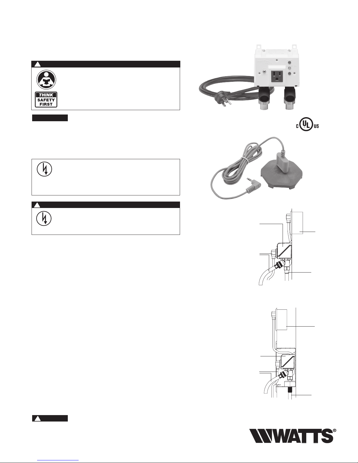
Leak Sensor
Model
A2C-M1
from
washing
machine
1
⁄2” solder connectors for exposed piping
Standardly furnished with 1⁄2” solder copper
adapters. Either connection may be used for the
hot or cold water supply.
Model
A2C-WB
from
washing
machine
Model A2C-M1
Electrical
power source
ground fault
protected
Water supply
One for cold
One for hot
Electrical
power source
ground fault
protected
Water supply
One for cold
One for hot
Model A2C-WB-M1
Includes wall mount box. Wall mount box has water
inlet connection holes spaced 23⁄8” center to center.
Furnished with 1⁄2” solder connectors. Either connection
may be used for the hot or cold water supply.
Page 2
Installing the A2C-M1 IntelliFlow
!
WARNING
®
Power MUST be off during installation or servicing of
the valve!
Do not plug valve into supply circuit until completion of
assembly.
NOTICE
For Vertical Installation Only!
1. Shut off electrical power supply.
2. Shut off both hot and cold water supply lines.
3. If retrofitting to an existing installation, disconnect the washing machine hoses from the existing shutoff valve(s).
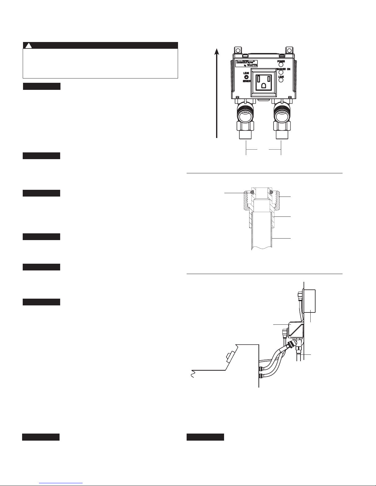
4. Loosen the two (2) adapter nuts and remove both adapters
from IntelliFlow
®
valve body.
5. Place adapter nuts over piping prior to soldering adapters.
6. Solder adapters onto piping.
NOTICE
Piping must be 2
3
⁄8” on center (Figure 3).
7. Place O-rings on adapter grooves (Figure 3A).
8.
Align and slip the valve body over adapters. Tighten adapter
nuts.
NOTICE
Do not over-tighten nuts.
To avoid cross threading, check thread alignment.
9. Connect the washing machine hoses to the IntelliFlow
®
’s
hot and cold water outlets.
10. Plug the washing machine into the IntelliFlow
NOTICE
®
’s electrical outlet.
Appliance current rating must not exceed 15 amps.
11. Plug the IntelliFlow®’s power cord into a house electrical
receptacle (Figure 4).
NOTICE
The IntelliFlow
®
requires a 120VAC, 60Hz, 15 amp ground-fault
protected receptacle.*
12. Install Leak Sensor
Install Upright
O-Ring
21⁄2”
Figure 3
Adapter Nut
Adapter
Water Supply Piping
Figure 3A
NOTICE
The IntelliFlow® will detect any current flow to the washing
machine when the washing machine is off. During startup or
at any time during troubleshooting, the IntelliFlow valve can be
reset to OFF condition by unplugging and reinstalling the leak
sensor.
13.
Turn on both hot and cold water supply lines, and check for leaks.
14. If there are no leaks, turn on the electrical power. Installation
of the A2C-M1 IntelliFlow
*Ground Fault Interrupter – A GFI circuit is not required
for proper operation of the IntelliFlow®, but is strongly
recommended as a safety device.
NOTICE
Use of the Watts Automatic Washing Machine Valve outlet
for appliances other than a washing machine is not recommended and voids the warranty.
®
is now complete.
Watts
A2C-M1
Washer
Power supply
ground fault
Water supply
Figure 4
NOTICE
Do not plug valve into electrical supply circuit until you
have completed installing the unit and reconnecting the
water supply lines.
2
protected
Page 3
Installing the IntelliFlow® Wall Box Unit (A2C-WB-M1)
!
WARNING
Power MUST be off during installation or servicing of
the valve!
Do not plug valve into supply circuit until completion of
assembly.
NOTICE
For Vertical Installation Only!
1. Shut off electrical power supply.
2. Shut off both hot and cold water supply lines.
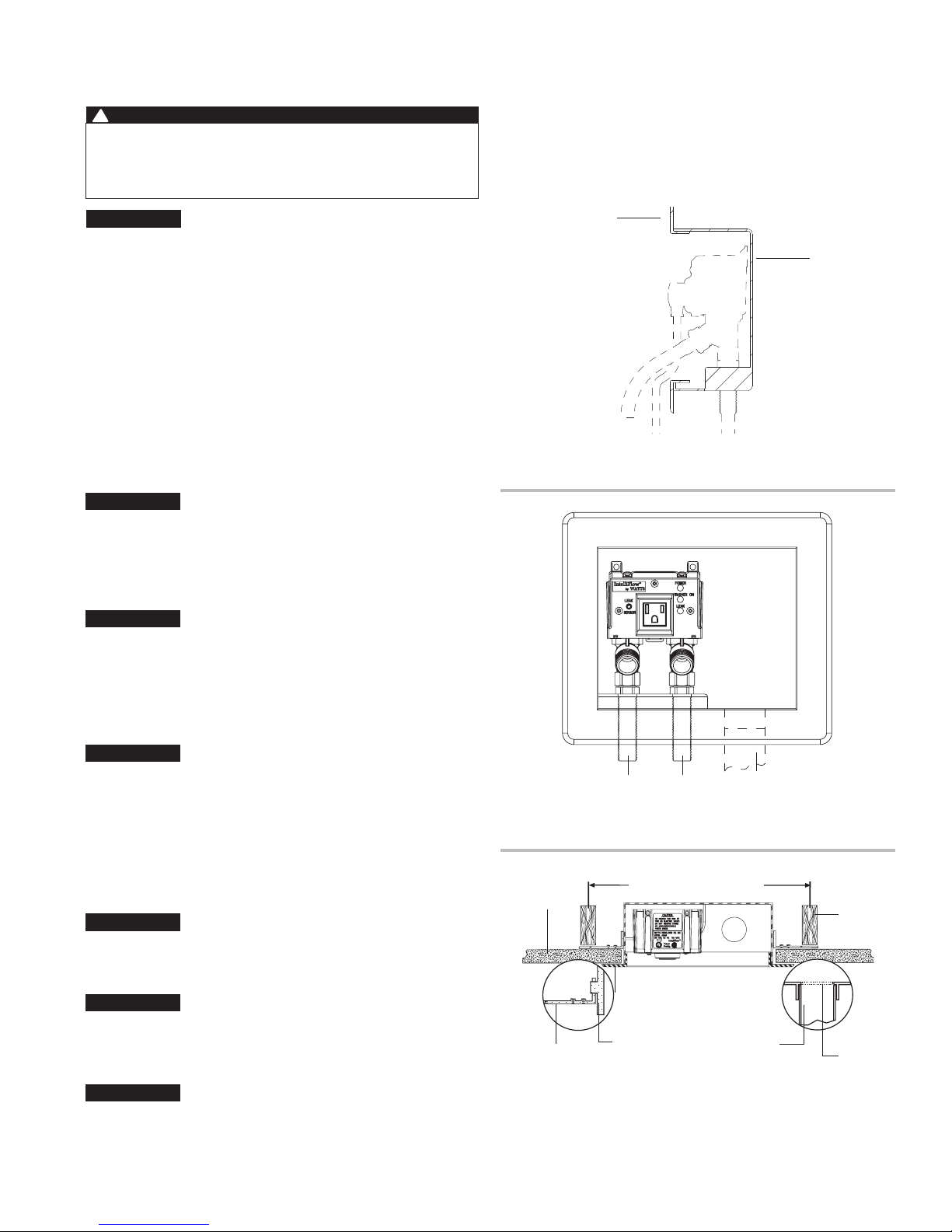
3. Remove trim plate (Figs. No.5 & 6) and set aside until
you’ve completed wall finishing (painting, wall papering,
paneling, etc.).
4. Install the four mounting tabs provided in slots on the sides
of the wall box enclosure (Fig. No. 7).
5. Position the A2C-WB-M1 between the wall studs as shown
in Fig. No. 7. Check that it is level and fasten the mounting
tabs to the studs.
6. Remove drain plug knock out. Install drain piping and water
supply piping to the appropriate IntelliFlow
Either IntelliFlow
®
connection may be used for the hot or
cold water supply.
NOTICE
Excessive heat from soldering can damage plastic components.
Use a heat sink to prevent damage.
7. Place O-rings on adapter grooves (Figure No. 3A).
8.
Align and slip the valve body over adapters. Tighten adapter
nuts.
NOTICE
Do not over tighten nuts.
To avoid cross threading, check thread alignment.
9. Prior to installing wall materials, turn on water supply (both
hot and cold) and test for leaks. Test drain piping for leaks.
10. Turn off water supply until you’ve completed installing
wall materials.
NOTICE
Installation must comply with local codes and ordinances.
Inspection and approval of installation by local authorities may
be required prior to installation of wall material. Check with local
plumbing authorities for requirements.
11. Once you’ve finished the wall, install trim plate, connect
washing machine water supply hoses to the IntelliFlow
valve and to the washing machine.
12. Plug washing machine into the IntelliFlow
NOTICE
Appliance current rating must not exceed 15 amps.
13. Insert the IntelliFlow
®
’s power cord into a house
electrical outlet.
NOTICE
The IntelliFlow® requires a 120VAC, 60Hz, 15 amp ground-fault
protected receptacle.*
14. Install Leak Sensor
NOTICE
The IntelliFlow® will detect any current flow to the washing
machine when the washing machine is off. During startup or
at any time during troubleshooting, the IntelliFlow valve can be
reset to OFF condition by unplugging and reinstalling the leak
sensor.
®
connection.
®
®
’s electrical outlet.
15. Turn on both hot and cold water supply lines, and check for
leaks.
16. If there are no leaks, turn on the electrical power. Installation of
the IntelliFlow
Trim Plate
®
A2C-WB-M1 Wall Box Unit is now complete.
Wall Box
Figure 5
(side view)
Trim Plate
Water supply connections Drain connection
Figure 6
(front view)
Finished
Wall
Mounting
Tabs (4)
16” on center – Typical
LISTED
3P47
U
R
L
Trim Plate
Mounting
Slots (4)
Drain
Studding
Knockout
Figure 7
(top view)
*Ground Fault Interrupter – A GFI circuit is not required
for proper operation of the IntelliFlow
recommended as a safety device.
®
, but is strongly
3
Wall
Drain
Page 4
Installing the Watts Model A2-LS Leak Sensor
Description:
The Watts Model A2-LS Leak Sensor plugs into the receptacle
on the front panel of the Watts IntelliFlow
A2-WB-M1. The base of the sensor is placed on the floor close
to the washing machine. Upon detection of water at the sensor
the IntelliFlow
washing machine hoses preventing catastrophic water damage.
®
immediately shuts off the water supply to the
®
Series A2C-M1 or
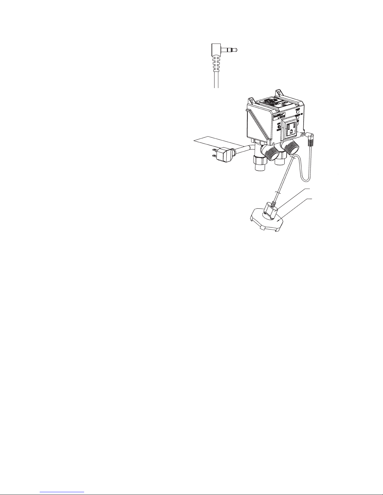
Installation:
1. Insert the leak sensor contacts into the two holes on the top
of the sensor base until the plug comes to a stop (Figure 2).
2. Place the sensor base on the floor behind the washing machine
as close to the fill hoses as possible. Insure that the sensor
base is lying flat with all feet in contact with the floor surface.
3. Insert the leak sensor plug (Figure 1) into the leak sensor
receptacle on front panel (Figure 2).
Note: Some washing machine models include circuitry that
causes a slight current draw at all times. These models
when connected to the IntelliFlow
supply to be energized continuously (Yellow LED: ON). The
IntelliFlow
leak sensor.
®
can be reset by unplugging and reinstalling the
®
can cause the water
Figure 1
Sensor Plug
Figure 2
Sensor Contacts
Sensor Base
4
Page 5
Troubleshooting Guide
PROBLEM SOLUTION
1. No water flow from either hot or cold water supply hose:
GREEN LED: OFF
GREEN LED: ON
YELLOW LED: OFF
RED LED: OFF / FAINT BLINK (Blink Every 3 Seconds)
GREEN LED: ON
YELLOW LED: OFF
RED LED: ON
This indicates that the valve did not open
GREEN LED: ON
YELLOW LED: OFF
RED LED: BLINKING
2. No water flow from one hose - (either Hot or Cold):
GREEN LED: ON
YELLOW LED: ON
RED LED: OFF / FAINT BLINK (Blink Every 3 Seconds)
1. Plug IntelliFlow® into electrical outlet.
2. Check electrical outlet for power (reset ground fault).
1. Plug washing machine into IntelliFlow
2. Confirm operation of washing machine by plugging it into a separate electri
®
and turn on washing machine.
-
cal outlet.
1. Leak sensor has detected water.
2. Dry off sensor
3. Check for broken or leaking hoses.
4. Unplug IntelliFlow
®
from electrical outlet, correct problem, then re-insert plug
into outlet to reset valve.
5. Turn on washing machine.
1. IntelliFlow
®
internal timing circuit has timed out.
YELLOW LED: OFF Turn off washing machine to reset timing circuit.
2. Unplug and then plug back in sensor
3. Calibrate sensors for 10 seconds
4. Turn on washing machine.
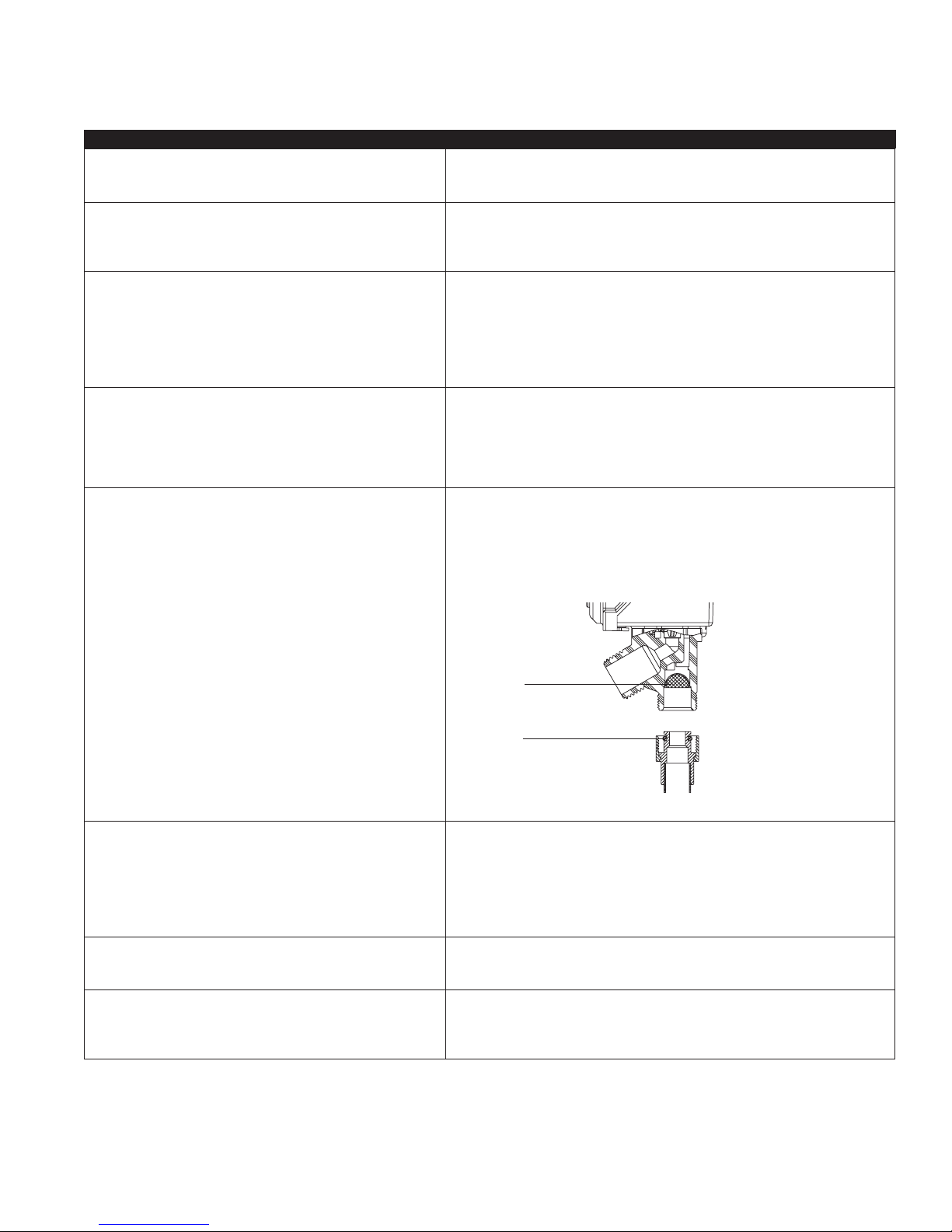
1. Service strainers on washing machine hoses.
2. Service strainers on IntelliFlow
Caution prior to servicing strainers, first remove power to IntelliFlow
unplugging, then shut off both hot and cold water supply to IntelliFlow
®
(see Figure 1).
®
by
®
.
Strainer
O-Ring
Figure 1
3. Yellow LED Remains On
GREEN LED: ON
YELLOW LED: ON
RED LED: OFF / FAINT BLINK
Some washing machine models include circuitry that causes a slight cur
rent draw at all times. These models when connected to the IntelliFlow
cause the water supply to be energized continuously (Yellow LED: ON). The
IntelliFlow
®
can be reset by unplugging and reinstalling the leak sensor. If this
does not resolve this issue, the use of the A2 IntelliTimer is required with the
system in use.
4. Unit feels warm: This condition is normal. Internal operating temperatures may cause unit to
feel warm to the touch.
5. Unit cycles ON/OFF: Installation in a horizontal position can cause abnormal overheating of the unit
which causes this cycling condition. Unit must be installed in an upright posi
tion as shown on pages 2 and 3.
®
can
-
-
5
Page 6
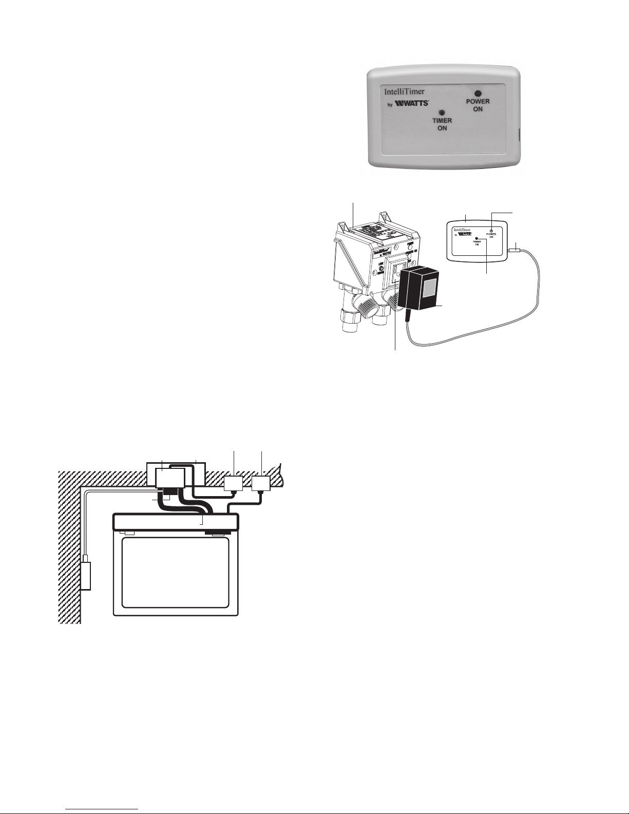
Accessories: Watts A2-IntelliTimer
The Watts A2-IntelliTimer is an optional accessory used in conjunction with the Watts IntelliFlow
Shutoff Valve. It is a remote timer which allows the IntelliFlow
be used in applications where the washing machine or a combination washer/dryer is 240VAC powered. (The IntelliFlow
®
Automatic Washing Machine
®
is not
®
to
compatible with 240VAC powered appliances). The timer initiates a two-hour cycle when the button is depressed.
The A2-IntelliTimer low voltage power supply is plugged into
the IntelliFlow
®
power outlet. The remote solid-state timer is
installed in a location that is convenient to the user and connected to the low voltage power supply.
Activation of the push button on the timer causes current flow,
which is detected by the IntelliFlow
®
. The IntelliFlow® then actuates the solenoid valves, allowing water to flow to the washing
machine. This also begins a timing sequence of two hours,
which, upon its completion de-energizes the IntelliFlow
®
, shutting off the flow of water to the washing machine. The timing
sequence can be interrupted by activating the push button a
second time.
A Green LED is illuminated whenever the A2-IntelliTimer is energized.
IntelliFlow
®
IntelliTimer
IntelliFlow
Power Outlet
®
Low Voltage
Power Supply
Power Lamp
Power Jack
Push On
Push Off
Power Cord
Typical Installation
IntelliFlow
Low Voltage
Power Supply
IntelliTimer
®
Wall Box
Washer Hoses
Washing
Machine
Power to
IntelliFlow
120
VAC
Power to
Washing
®
Machine
240
VAC
6
Page 7

Front Panel Status Indicators
GREEN LED: ON: Unit powered This lamp is illuminated whenever the IntelliFlow® is plugged into
a powered wall outlet.
YELLOW LED: ON: Water supply Open. This lamp is illuminated whenever the IntelliFlow
®
senses
OFF: Water Supply Closed. current flow (the washing machine is turned on).
It is off when the washing machine is turned off.
NOTICE
Some washing machine models include circuitry that
causes a slight current draw at all times. These models when
connected to the IntelliFlow
energized continuously (Yellow LED: ON).
Sensor Plug
®
can cause the water supply to be
RED LED: ON: Leak Sensed. This lamp is illuminated when the leak sensor is installed and
water has been detected at the sensor. The water supply to the
washing machine hoses are interrupted when a leak is detected.
BLINKING: Unit Timed Out – This lamp blinks whenever the internal timing circuit has timed
out and has shut off the water supply to the washing machine
hoses. Turning the washing machine Off then On will reset the
timing circuit.
FAINT BLINK: (3-5 seconds) – This condition indicates the leak sensor is unplugged. To provide
the maximum level of protection, it is recommended that the
leak sensor be installed at all times.
What is Surge Protection?
In many locations, changes in the AC voltage supply to the home by the
electrical utility company can occur. Both lower voltage (brownouts) and
high voltage (surges) can occur. Lightning strikes can also cause high
voltage spikes to occur.
All electronic equipment is designed to operate properly within
a voltage range. However, high voltage surges or spikes can
damage sensitive circuitry within electronic equipment.
Surge protectors prevent voltage spikes from reaching
electronic equipment.
What is Ground Fault Protection?
In many locations, an electrical differential between an electrical ground
and a water pipe ground can exist. A person touching both grounds
could receive a shock that may cause injury or death. A ground fault
interrupter circuit (GFI) detects the differential and removes electrical
power before injury can occur.
The IntelliFlow® does not cause or change the electrical differential that exists.
7
Page 8

IntelliFlow® Retrofit Kit Options
IntelliFlow
Retrofit Installation Kit KA2-BD
Order No. 0004800
If Your Current Installation
Looks Like:
®
These mounting kits are specifically used to install the Watts Model A2C-M1 IntelliFlow® automatic
washing machine shutoff valve to existing drain valves.
Final Installation Will
Look Like:
KA2-BD
left or right drain
IntelliFlow
Retrofit Kit KA2-R
Order No. 0004805
®
This kit is used to replace the following Watts IntelliFlow® Models: A2-WB,
A2C-WB, A2C-WB-M with the new IntelliFlow® Model A2C-M1.
If Your Current Installation Looks Like:
or
Wall box style with #2 Style, A2-WB, A2C-WB or A2C-WB-M
If Your Current Installation
Looks Like:
center drain
KA2-R
Final Installation Will
Look Like:
KA2-BD
Final Installation Will Look Like:
A2C-M1
IntelliFlow
Retrofit Kit KA2-A
Order No. 0004804
Wall box style with #2 Style, A2, A2C or A2C-M
Limited Warranty: Watts (the “Company”) warrants each product to be free from defects in material and workmanship under normal usage for a period of one year from the date of original shipment.
In the event of such defects within the warranty period, the Company will, at its option, replace or recondition the product without charge.
THE WARRANTY SET FORTH HEREIN IS GIVEN EXPRESSLY AND IS THE ONLY WARRANTY GIVEN BY THE COMPANY WITH RESPECT TO THE PRODUCT. THE COMPANY MAKES NO OTHER
WARRANTIES, EXPRESS OR IMPLIED. THE COMPANY HEREBY SPECIFICALLY DISCLAIMS ALL OTHER WARRANTIES, EXPRESS OR IMPLIED, INCLUDING BUT NOT LIMITED TO THE IMPLIED
WARRANTIES OF MERCHANTABILITY AND FITNESS FOR A PARTICULAR PURPOSE.
The remedy described in the first paragraph of this warranty shall constitute the sole and exclusive remedy for breach of warranty, and the Company shall not be responsible for any incidental, special
or consequential damages, including without limitation, lost profits or the cost of repairing or replacing other property which is damaged if this product does not work properly, other costs resulting
from labor charges, delays, vandalism, negligence, fouling caused by foreign material, damage from adverse water conditions, chemical, or any other circumstances over which the Company has no
control. This warranty shall be invalidated by any abuse, misuse, misapplication, improper installation or improper maintenance or alteration of the product.
Some States do not allow limitations on how long an implied warranty lasts, and some States do not allow the exclusion or limitation of incidental or consequential damages. Therefore the above
limitations may not apply to you. This Limited Warranty gives you specific legal rights, and you may have other rights that vary from State to State. You should consult applicable state laws to
determine your rights. SO FAR AS IS CONSISTENT WITH APPLICABLE STATE LAW, ANY IMPLIED WARRANTIES THAT MAY NOT BE DISCLAIMED, INCLUDING THE IMPLIED WARRANTIES OF
MERCHANTABILITY AND FITNESS FOR A PARTICULAR PURPOSE, ARE LIMITED IN DURATION TO ONE YEAR FROM THE DATE OF ORIGINAL SHIPMENT.
®
This kit is used to replace the following Watts washing machine shutoff valves: the wall mounted
Watts Models #2 Duo-Cloz valve and the wall mounted IntelliFlow® Models: A2, A2C, A2C-M with
the new Watts IntelliFlow® Model A2C-M1.
If Your Current Installation Looks Like:
or
Final Installation Will Look Like:
KA2-A
A2C-M1
IS-A2C-M1_A2C-WB-M1 1906 EDP# 1911430 © 2019 Watts
USA: T: (978) 689-6066 • F: (978) 975-8350 • Watts.com
Canada: T: (905) 332-4090 • F: (905) 332-7068 • Watts.ca
Latin America: T: (52) 81-1001-8600 • Watts.com
Page 9

Watts IntelliFlow
®
Válvula de cierre automático para lavadora
modelo A2C-M1, A2C-WB-M1
!
ADVERTENCIA
Lea este manual ANTES de utilizar este equipo.
Si no lee y respeta toda la información sobre seguridad
y uso, pueden ocasionarse muertes, lesiones personales
graves, daños materiales o daños al equipo.
Conserve este manual para consultarlo en el futuro.
IS-A2C-M1/A2C-WB-M1_SP
AVISO
Esta unidad no es compatible con las lavadoras que usan
alimentación de 240VCA ni con las lavadoras/secadoras que
usan alimentación de 240VCA. Es posible utilizar un dispositivo
Watts A2-IntelliTimer (de venta por separado) en combinación
con IntelliFlow
®
para las lavadoras o lavadoras/secadoras
alimentadas por 240VCA. (Consulte la página 5).
*Esta válvula requiere un circuito de 120VCA,
60Hz, 20amp con protección de falla a tierra.
*Interruptor de falla a tierra: este circuito no es
obligatorio para el funcionamiento adecuado de IntelliFlow
pero se recomienda utilizarlo como dispositivo de seguridad.
!
ADVERTENCIA
Protección contra sobrecargas: si bien no es
obligatorio contar con un protector contra sobrecargas
para el funcionamiento adecuado de IntelliFlow
recomienda utilizarlo, especialmente en zonas donde
las sobrecargas o la caída de rayos sean frecuentes.
Instrucciones de funcionamiento
La válvula de cierre automático para lavadora Watts IntelliFlow® está equipada con un
avanzado dispositivo de detección de corriente eléctrica. Cuando se enciende la
lavadora, el dispositivo detecta el flujo de corriente hacia la lavadora y activa las válvulas
de agua a solenoides para permitir que el agua fluya hacia la lavadora. Cuando la
lavadora se apaga al finalizar el ciclo de lavado, el dispositivo detecta que no hay
corriente y cierra las válvulas de agua. La válvula IntelliFlow
próxima vez que se enciende la lavadora.
El sensor de fugas ofrece protección adicional contra el daño provocado por el agua
mientras la lavadora está en funcionamiento. Cuando el sensor detecta agua, el flujo de
agua hacia la manguera de la lavadora se cierra de inmediato.
Al instalar una válvula IntelliFlow
®
, protege su hogar contra los nocivos daños que puede
provocar el agua cuando hay explosiones o pérdidas en la manguera de la lavadora.
Especificaciones de funcionamiento
Potencia eléctrica: 120VCA, 60 Hz
Requisitos del disyuntor: interruptor de
falla a tierra de 20A*
Máx. potencia de corriente del aparato:
15A
Consumo de corriente: 20mA (con el
aparato apagado)
Cable eléctrico: SJT 14 AWG de 6 pies
no es obligatorio para el funcionamiento adecuado de IntelliFlow
utilizarlo como dispositivo de seguridad. De acuerdo con el Código Eléctrico Nacional,
NFPA 70, sección 210.11, que trata la necesidad de circuitos ramificados, se necesita
al menos un circuito ramificado de 20amperios para el suministro de los tomacorrientes
del ambiente del lavadero, de acuerdo con la sección 210.52(F). Este circuito no debe
incluir ningún otro tomacorriente.
ADVERTENCIA
!
*Protección contra sobrecargas: si bien no es obligatorio contar con un protector
contra sobrecargas para el funcionamiento adecuado de IntelliFlow
utilizarlo, especialmente en zonas donde las sobrecargas o la caída de rayos
sean frecuentes.
A2C-M1 IntelliFlow
Número de patente 6.003.536
®
,
®
, se
®
queda cerrada hasta la
Máx. temperatura: 82 °C (180 °F)
Máx. presión: 10,3 bares (150psi)
Máx. diferencial de presión
de funcionamiento: 5,5 bares (80psi)
Cuerpo de la válvula: polisulfona reforzada
Piezas de goma: Buna-N, EPDM
*Interruptor de falla a tierra: este circuito
®
, pero se recomienda
®
, se recomienda
®
Sensor de fugas
Modelo
A2C-M1
Desde la
lavadora
Fuente de
potencia
con protección
de falla
a tierra
Suministro de agua:
uno para agua
fría y uno para
agua caliente
Modelo A2C-M1
Conectores de soldadura de 1⁄2” para cañerías expuestas
Se proporciona estándar con adaptadores de cobre de
soldadura de
conexiones para el suministro de agua caliente o fría.
Modelo
A2C-WB
Desde la
lavadora
1
⁄2”. Puede usarse cualquiera de las
Fuente de
potencia con
protección
de falla a tierra
Suministro de agua:
uno para agua
fría y uno para
agua caliente
Modelo A2C-WB-M1
Incluye caja de montaje en pared. La caja de montaje
en pared tiene orificios de conexión de entrada de agua
con una distancia de 23⁄8” entre centro y centro. Se
suministra con conectores de soldadura de 1⁄2”. Puede
usarse cualquiera de las conexiones para el suministro
de agua caliente o fría.
Page 10

Instalación de la válvula A2C-M1 IntelliFlow
ADVERTENCIA
!
®
Durante las operaciones de instalación o mantenimiento
de la válvula, la alimentación DEBE estar desactivada.
No conecte la válvula al circuito de alimentación hasta
finalizar la instalación.
AVISO
Solo para instalación vertical.
1. Desactive la alimentación eléctrica.
2. Cierre el suministro de agua caliente y fría.
3. Si está adaptando una instalación previa, desconecte las
mangueras de la lavadora de las válvulas de cierre previas.
4. Afloje las tuercas de los dos (2) adaptadores y quite los
adaptadores del cuerpo de la válvula IntelliFlow
®
.
5. Coloque las tuercas de los adaptadores sobre las cañerías
antes de soldar los adaptadores.
6. Suelde los adaptadores en la cañería.
AVISO
Las cañerías deben tener un tamaño de 2
3
⁄8” en el centro (Figura 3).
7. Coloque las juntas tóricas en las muescas del adaptador
(Figura 3A).
8.
Alinee el cuerpo de la válvula y deslícelo sobre los
adaptadores. Ajuste las tuercas de los adaptadores.
AVISO
No ajuste en exceso las tuercas.
Para evitar estropear la rosca, verifique la alineación de la rosca.
9. Conecte las mangueras de la lavadora a las salidas de agua
fría y caliente de la válvula IntelliFlow
10. Conecte la lavadora al tomacorriente de IntelliFlow
AVISO
®
.
®
.
La corriente del aparato no puede superar los 15amperios.
11. Conecte el cable de alimentación de IntelliFlow® a un
receptáculo eléctrico hogareño (Figura 4).
AVISO
La válvula IntelliFlow
®
requiere un receptáculo con protección de
falla a tierra de 120VCA, 60Hz y 15amp.*
12. Instale el sensor de fugas.
Instalación vertical
Junta tórica
21⁄2”
Figura3
Tuerca del adaptador
Adaptador
Cañería de
suministro de agua
Figura3A
AVISO
La válvula IntelliFlow® detecta cualquier flujo de corriente hacia
la lavadora que se produzca mientras la máquina está apagada.
Durante la puesta en marcha o en cualquier momento durante una
reparación, es posible restablecer el estado desactivado de la
válvula IntelliFlow desconectando y reinstalando el sensor de fugas.
13.
Encienda las líneas de suministro de agua fría y caliente y
compruebe que no haya fugas.
14. Si no hay fugas, encienda la alimentación eléctrica. Ha
finalizado la instalación de la válvula A2C-M1 IntelliFlow
*Interruptor de falla a tierra: este circuito no es
obligatorio para el funcionamiento adecuado de
IntelliFlow
dispositivo de seguridad.
AVISO
No se recomienda usar el tomacorriente de la válvula
automática para lavadora Watts en otros tipos de
aparatos. Hacerlo anula la garantía.
®
, pero se recomienda utilizarlo como
Watts
A2C-M1
Lavadora
®
.
Alimentación
eléctrica con
protección de
falla a tierra
Suministro
de agua
Figura4
AVISO
No conecte la válvula al circuito de alimentación eléctrica
hasta terminar de instalar la unidad y reconectar las líneas
de suministro de agua.
2
Page 11

Instalación de la unidad de caja de montaje en
pared IntelliFlow® (A2C-WB-M1)
ADVERTENCIA
!
Durante las operaciones de instalación o mantenimiento
de la válvula, la alimentación DEBE estar desactivada.
No conecte la válvula al circuito de alimentación hasta
finalizar la instalación.
15. Encienda las líneas de suministro de agua fría y caliente y
compruebe que no haya fugas.
16. Si no hay fugas, encienda la alimentación eléctrica. Ha
finalizado la instalación de la unidad de caja de montaje en
pared IntelliFlow
®
A2C-WB-M1.
AVISO
Solo para instalación vertical.
1. Desactive la alimentación eléctrica.
2. Cierre el suministro de agua caliente y fría.
3. Quite la placa de protección (Fig. 5 y 6) y déjela a un
costado hasta que termine los trabajos en la pared (pintura,
empapelado, colocación de paneles, etc.).
4. Instale las cuatro lengüetas de montaje suministradas en las
ranuras ubicadas a los laterales del envolvente para pared (Fig. 7).
5. Coloque la A2C-WB-M1 entre los montantes de pared,
como se muestra en la Figura 7. Controle la nivelación y
ajuste las lengüetas de montaje en los montantes.
6. Quite el tope de drenaje. Instale las cañerías de drenaje y
de suministro de agua en la conexión de IntelliFlow
correspondiente. Puede usarse cualquiera de las conexiones
de IntelliFlow
AVISO
®
para el suministro de agua caliente o fría.
®
El calor excesivo provocado por la soldadura puede dañar los
componentes plásticos. Use un disipador para evitar daños.
7. Coloque las juntas tóricas en las muescas del adaptador
(Figura 3A).
8.
Alinee el cuerpo de la válvula y deslícelo sobre los adaptadores.
Ajuste las tuercas de los adaptadores.
AVISO
No ajuste en exceso las tuercas.
Para evitar estropear la rosca, verifique la alineación de la rosca.
9. Antes de instalar los materiales de la pared, encienda el
suministro de agua (fría y caliente) y compruebe si hay
fugas. Controle si hay fugas en la cañería de drenaje.
10. Desactive el suministro de agua hasta que haya finalizado la
instalación de los materiales de la pared.
AVISO
La instalación debe realizarse de acuerdo con los códigos y las
ordenanzas locales. En algunos lugares, se requiere la inspección
y aprobación de la instalación por parte de las autoridades locales
antes de la instalación de los materiales de la pared. Consulte a
sus autoridades correspondientes para conocer los requisitos.
11. Una vez que termine de trabajar en la pared, instale la placa
de protección y conecte las mangueras de suministro de
agua de la lavadora a la válvula IntelliFlow
12. Conecte la lavadora al tomacorriente de IntelliFlow
AVISO
®
y a la lavadora.
®
.
La corriente del aparato no puede superar los 15amperios.
13. Inserte el cable de alimentación de IntelliFlow® en un
tomacorriente hogareño.
AVISO
La válvula IntelliFlow
®
requiere un receptáculo con protección de
falla a tierra de 120VCA, 60Hz y 15amp.*
14. Instale el sensor de fugas.
AVISO
La válvula IntelliFlow® detecta cualquier flujo de corriente hacia
la lavadora que se produzca mientras la máquina está apagada.
Durante la puesta en marcha o en cualquier momento durante una
reparación, es posible restablecer el estado desactivado de la
válvula IntelliFlow desconectando y reinstalando el sensor de fugas.
Placa de protección
Caja de
montaje en
pared
Figura5
(vista lateral)
Placa de protección
Conexiones de suministro de agua
Conexión de drenaje
Figura6
(vista frontal)
16” en el centro
Pared
terminada
Lengüetas de
montaje (4)
(config. típica)
LISTED
3P47
U
R
L
Placa de
protección
Ranuras de
montaje (4)
Drenaje
Montante
de pared
Tope de
drenaje
Figura7
(vista superior)
*Interruptor de falla a tierra: este circuito no es obligatorio
para el funcionamiento adecuado de IntelliFlow
recomienda utilizarlo como dispositivo de seguridad.
®
, pero se
3
Page 12

Instalación del sensor de fugas Watts modelo A2-LS
Descripción:
El sensor de fugas Watts modelo A2-LS se conecta al orificio
ubicado en el panel frontal de la válvula Watts IntelliFlow
A2C-M1 o A2-WB-M1. La base del sensor se coloca en el piso,
cerca de la lavadora. Cuando el sensor IntelliFlow
cierra de inmediato el suministro de agua hacia la manguera de la
lavadora para evitar daños graves a causa del agua.
®
serie
®
detecta agua,
Instalación:
1. Inserte los contactos del sensor de fugas en los dos orificios
ubicados en la parte superior de la base del sensor hasta
que hagan tope (Figura 2).
2. Coloque la base del sensor en el piso, detrás de la
lavadora, lo más cerca posible de las mangueras de llenado.
Asegúrese de que la base del sensor esté bien apoyada,
con todas las patas en contacto con la superficie del piso.
3. Inserte el conector del sensor de fugas (Figura 1) en el orificio
del sensor de fugas del panel frontal (Figura 2).
Nota: Algunos modelos de lavadora tienen circuitos que
provocan un consumo de corriente leve en todo
momento. Si se conectan estos modelos a la válvula
IntelliFlow
el suministro de agua (LED amarillo: ENCENDIDO). Es
posible restablecer la válvula IntelliFlow
y se reinstala el sensor de fuga.
®
, es posible que se alimente constantemente
®
si se desconecta
Figura1
Conector del sensor
Figura2
Contactos del sensor
Base del sensor
4
Page 13

Guía de resolución de problemas
PROBLEMA SOLUCIÓN
1. No hay flujo de agua de la manguera de suministro de
agua caliente o fría:
LED VERDE: APAGADO
LED VERDE: ENCENDIDO
LED AMARILLO: APAGADO
LED ROJO: APAGADO/PARPADEO DÉBIL
(Parpadeocada 3segundos)
LED VERDE: ENCENDIDO
LED AMARILLO: APAGADO
LED ROJO: ENCENDIDO
Esto indica que la válvula no se abrió.
LED VERDE: ENCENDIDO
LED AMARILLO: APAGADO
LED ROJO: PARPADEO
2. No hay flujo de agua de una manguera (ya sea caliente
ofría):
LED VERDE: ENCENDIDO
LED AMARILLO: ENCENDIDO
LED ROJO: APAGADO/PARPADEO DÉBIL
(Parpadeocada 3segundos)
1. Conecte el IntelliFlow® en el tomacorriente.
2. Verifique que el tomacorriente cuente con corriente eléctrica
(reinicie en caso de falla de tierra).
®
1. Conecte la lavadora en el IntelliFlow
y encienda la lavadora.
2. Conecte la lavadora en un tomacorriente separado para confirmar
sufuncionamiento.
1. El sensor de fuga ha detectado agua.
2. Seque el sensor.
3. Verifique que las mangueras no estén rotas y no tengan fugas.
4. Desconecte el IntelliFlow
®
del tomacorriente, corrija el problema, luego
conecte nuevamente en el tomacorriente para reiniciar la válvula.
5. Encienda la lavadora.
1. El circuito interno de sincronización del IntelliFlow
®
ha agotado el tiempo
deespera.
LED AMARILLO: APAGADO Apague la lavadora para reiniciar el circuito
desincronización.
2. Desconecte y conecte nuevamente al sensor.
3. Calibre los sensores durante 10segundos.
4. Encienda la lavadora.
1. Coladores de servicio de las mangueras de la lavadora.
2. Coladores de servicio en IntelliFlow
Tenga cuidado antes de dar mantenimiento a los coladores; primero
desconecte el IntelliFlow
®
para interrumpir la corriente, luego cierre el
suministro de agua fría y caliente al IntelliFlow
®
(consulte la figura1).
®
.
Filtro
Junta tórica
Figura 1
3. El LED amarillo permanece encendido
LED VERDE: ENCENDIDO
LED AMARILLO: ENCENDIDO
LED ROJO: APAGADO/PARPADEO DÉBIL:
4. La unidad se siente tibia al tacto: Esta condición es normal. Las temperaturas internas de operación pueden
5. La unidad se enciende y apaga: La instalación en una posición horizontal puede provocar sobrecalentamiento
Algunos modelos de lavadoras incluyen circuitos que generan un pequeño
consumo constante de corriente. Estos modelos, cuando están conectados
al IntelliFlow
manera continua (LED amarillo: ENCENDIDO). El IntelliFlow
®
, pueden provocar que el suministro de agua esté energizado de
®
se puede reiniciar
al desconectarlo y reinstalando el sensor de fugas. Si esto no resuelve el
problema, se requiere utilizar el IntelliTimer A2 con el sistema en uso.
generar que la unidad se sienta tibia al tacto.
irregular de la unidad, lo cual provoca esta condición de ciclado. La unidad se
debe instalar en una posición vertical, como se muestra en las páginas 2 y 3.
5
Page 14

Accesorios: Watts A2-IntelliTimer
El dispositivo Watts A2-IntelliTimer es un accesorio opcional que
se usa junto con la válvula de cierre automático para lavadora
Watts IntelliFlow
permite utilizar IntelliFlow
la lavadora/secadora tiene una alimentación de 240VCA. (La
válvula IntelliFlow
a 240VCA). Cuando se presiona el botón, el temporizador inicia
un ciclo de dos horas.
El suministro de alimentación de baja tensión del A2-IntelliTimer
se conecta al tomacorriente de la válvula IntelliFlow
temporizador remoto de estado sólido se instala en un lugar
cómodo para el usuario, conectado a la alimentación eléctrica
de baja tensión.
Al activar el botón del temporizador, se genera un flujo de
corriente que es detectado por IntelliFlow
dispositivo IntelliFlow
que el agua fluya hacia la lavadora. Esta misma acción inicia
una secuencia de temporización de dos horas que, al finalizar,
desactiva la válvula IntelliFlow
lavadora. La secuencia de temporización puede interrumpirse si
se vuelve a presionar el botón.
Cada vez que el A2-IntelliTimer recibe energía, se ilumina un
indicador LED verde.
®
. Se trata de un temporizador remoto que
®
®
en instalaciones donde la lavadora o
no es compatible con aparatos alimentados
®
. El
®
®
activa las válvulas a solenoides y permite
®
y cierra el flujo de agua hacia la
. En consecuencia, el
IntelliFlow
®
IntelliTimer
Alimentación
eléctrica de
baja tensión
Lámpara de
alimentación
Conector de
alimentación
Botón de
encendido/
apagado
Cable de
alimentación
Instalación típica
IntelliFlow
Alimentación eléctrica de baja tensión
IntelliTimer
Caja de
montaje
®
en pared
Mangueras de
la lavadora
Lavadora
Alimentación
hacia
120
VCA
®
IntelliFlow
Alimentación
hacia la
lavadora
240
VCA
Tomacorriente
de IntelliFlow
®
6
Page 15

Indicadores de estado del panel frontal
LED VERDE: ENCENDIDO: Unidad encendida Esta lámpara se ilumina cuando la válvula IntelliFlow® está
conectada a un tomacorriente con alimentación eléctrica.
LED AMARILLO: ENCENDIDO: Suministro de agua abierto Esta lámpara se ilumina cuando el sensor de IntelliFlow
®
detecta
APAGADO: Suministro de agua cerrado. el flujo de corriente (y la lavadora está encendida).
Está apagado cuando la lavadora se desactiva.
AVISO
Algunos modelos de lavadora tienen circuitos que provocan un
consumo de corriente leve en todo momento. Si se conectan
estos modelos a la válvula IntelliFlow
alimente constantemente el suministro de agua
Conector del sensor
®
, es posible que se
(LED amarillo: ENCENDIDO).
LED ROJO: ENCENDIDO: Fuga detectada. Esta lámpara se enciende cuando el sensor de fugas está instalado y
se detecta agua en el sensor. El suministro de agua a las
mangueras de la lavadora se interrumpe cuando se detecta una fuga.
PARPADEANTE: Plazo de la unidad finalizado Esta lámpara parpadea cuando finaliza el plazo del circuito del
termporizador interno y se cierra el suministro de agua hacia las
mangueras de la lavadora. Si se apaga y se vuelve a encender
la lavadora, el circuito del temporizador se restablece.
PARPADEO DÉBIL: (3 a 5 segundos) Este estado indica que el sensor de fugas está desconectado.
Para contar con el máximo nivel de protección, es recomendable
que el sensor de fugas esté instalado en todo momento.
¿Qué es la protección contra sobrecargas?
En muchos lugares, es frecuente que la tensión de CA suministrada por
la empresa de servicios cambie repentinamente. Pueden producirse
bajas de tensión o picos de tensión (sobrecarga). La caída de rayos
también puede provocar picos de tensión.
Todos los equipos electrónicos están diseñados para funcionar
adecuadamente aunque haya una cierta variación de tensión.
No obstante, los picos de tensión pueden dañar los circuitos
sensibles de los equipos electrónicos.
Los protectores contra descargas evitan que los picos de
tensión lleguen al equipo electrónico.
¿Qué es la protección de falla a tierra?
En muchos lugares, existe un diferencial eléctrico entre la puesta a tierra
eléctrica y de la tubería de agua. Si una persona toca las dos conexiones de puesta a tierra, puede sufrir un choque dañino o incluso mortal.
El circuito del interruptor de falla a tierra (GFI) detecta el diferencial y
elimina la electricidad para evitar lesiones.
La válvula IntelliFlow® no provoca ni modifica el diferencial
eléctrico.
7
Page 16

Opciones de kits de adaptación IntelliFlow
®
IntelliFlow
Kit de instalación de adaptación
KA2-BD N.° de pedido 0004800
Si la instalación actual es así:
®
Estos kits de montaje se utilizan específicamente para instalar la válvula de cierre automático para
lavadora Watts IntelliFlow® modelo A2C-M1 en válvulas de drenaje ya instaladas.
La instalación final será así:
KA2-BD
Drenaje izquierdo o derecho
IntelliFlow
Kit de adaptación KA2-R
N.° de pedido 0004805
®
Este kit permite sustituir los modelos de Watts IntelliFlow® A2-WB, A2C-WB, A2C-WB-M con el
nuevo modelo IntelliFlow® A2C-M1.
Si la instalación actual es así:
o
Caja de montaje en pared estilo 2, A2-WB, A2C-WB o A2C-WB-M
Si la instalación actual es así:
Drenaje central
KA2-R
La instalación final será así:
KA2-BD
La instalación final será así:
A2C-M1
IntelliFlow
Kit de adaptación KA2-A
N.° de pedido 0004804
Caja de montaje en pared estilo 2, A2, A2C o A2C-M
Garantía limitada: Watts Regulator Co. (la “Compañía”) garantiza que los productos no presentarán defectos en el material y la mano de obra cuando se usen en forma normal, durante un periodo de
un año a partir de la fecha de envío original. Si se produjeran dichos defectos durante el periodo cubierto por la garantía, la Compañía podrá, según su criterio, optar por reemplazar o reacondicionar
el producto sin cargo alguno.
LA GARANTÍA AQUÍ ESTABLECIDA SE CONFIERE EXPRESAMENTE Y ES LA ÚNICA GARANTÍA OTORGADA POR LA COMPAÑÍA CON RESPECTO AL PRODUCTO. LA COMPAÑÍA NO EXTIENDE
NINGUNA OTRA GARANTÍA, EXPLÍCITA O IMPLÍCITA. LA COMPAÑÍA SE EXIME ESPECÍFICAMENTE A TRAVÉS DE ESTE DOCUMENTO DE CUALQUIER OTRA GARANTÍA, EXPLÍCITA O IMPLÍCITA,
INCLUIDAS ENTRE OTRAS, LAS GARANTÍAS IMPLÍCITAS DE COMERCIABILIDAD Y APTITUD PARA UN FIN EN PARTICULAR.
El recurso descrito en el primer párrafo de esta garantía será el único y exclusivo en caso de incumplimiento de la garantía, y la Compañía no será responsable por ningún daño incidental, especial
ni indirecto, lo cual incluye, a título meramente enunciativo, lucro cesante o el costo de reparar o reemplazar otros bienes que se hayan dañado si este producto no funciona correctamente, otros
costos resultantes de mano de obra, retrasos, vandalismo, negligencia, contaminación ocasionada por materia extraña, daños por condiciones adversas del agua, productos químicos o cualquier otra
circunstancia sobre la cual la Compañía no tenga control. Esta garantía quedará anulada por maltrato, uso indebido, mal uso, instalación incorrecta o mantenimiento inadecuado o alteración del producto.
Algunos estados no permiten limitaciones sobre la duración de las garantías implícitas y algunos estados no permiten la exclusión ni la limitación de daños incidentales o indirectos. Por lo tanto, es
posible que las limitaciones anteriores no correspondan en su caso. Esta Garantía limitada le proporciona derechos legales específicos, y usted también puede tener otros derechos que varían de un
estado a otro. Deberá consultar las leyes estatales correspondientes para poder determinar sus derechos. MIENTRAS ASÍ LO PERMITA LA LEGISLACIÓN ESTATAL APLICABLE, LAS GARANTÍAS
IMPLÍCITAS QUE NO PUEDAN RECHAZARSE, INCLUIDAS, A MODO ILUSTRATIVO, LAS GARANTÍAS IMPLÍCITAS DE COMERCIABILIDAD Y APTITUD PARA UN FIN PARTICULAR, TENDRÁN UNA
LIMITACIÓN LIMITADA DE UN AÑO A PARTIR DE LA FECHA DE ENVÍO ORIGINAL.
®
Si la instalación actual es así:
Este kit permite sustituir la válvulas de cierre para lavadoras Watts de montaje en pared modelo 2
Duo-Cloz y los modelos IntelliFlow® de montaje en pared A2, A2C, A2C-M con el nuevo modelo
Watts IntelliFlow® A2C-M1.
La instalación final será así:
o
KA2-A
A2C-M1
IS-A2C-M1_A2C-WB-M1_SP 1906 EDP# 1911430 © 2019 Watts
EE.UU.: Tel: (978) 689-6066 • Fax: (978) 975-8350 • Watts.com
Canadá: Tel: (905) 332-4090 • Fax: (905) 332-7068 • Watts.ca
Latinoamérica: Tel: (52) 81-1001-8600 • Watts.com
Page 17

Watts IntelliFlow
®
Robinet d'arrêt pour machine à laver
automatique modèle A2C-M1, A2C-WB-M1
!
AVERTISSEMENT
Lisez ce manuel AVANT d’utiliser cet équipement.
Le non-respect de cette instruction ou des informations
relatives à la sécurité et à l'utilisation risque de provoquer
des blessures, des dégâts matériels et des dommages à
l'équipement.
Conservez ce manuel pour référence ultérieure.
IS-A2C-M1/A2C-WB-M1_FR
AVIS
Cet appareil n'est pas compatible avec les machines à laver ou
les ensembles lave-linge/sèche-linge fonctionnant avec une
alimentation 240Vc.a. Un Watts A2-IntelliTimer (vendu
séparément) peut être utilisé avec le robinet d'arrêt IntelliFlow
®
avec les machines à laver ou les lave-linge/sèche-linge avec une
alimentation 240Vc.a. (Voir page5)
*Ce robinet exige un circuit de protection
contre les fuites de terre de 120Vc.a.,
60Hz, 20A.
*Disjoncteur de fuite de terre (GFI): ce type de disjoncteur n'est
pas obligatoire pour que l'IntelliFlow
mais ce dispositif de sécurité est fortement recommandé.
AVERTISSEMENT
!
Protection contre les surtensions: bien qu'un
limiteur de surtension ne soit pas indispensable au
bon fonctionnement de l'IntelliFlow
conseillé, particulièrement dans les régions où les
surtensions ou la foudre sont fréquentes.
®
fonctionne correctement,
®
, il est fortement
Instructions d'utilisation
Le robinet d'arrêt automatique Watts IntelliFlow® pour machine à laver est équipé d'un capteur
de courant électrique ultramoderne. Lorsque la machine à laver est mise en route, l'appareil
détecte le flux de courant circulant dans la machine à laver. Cela actionne les robinets
électromagnétiques, permettant à l'eau de circuler vers la machine à laver. Lorsque la machine à
laver s'arrête après le cycle de lavage complet, l'appareil détecte l'absence de courant et ferme
les robinets. L'IntelliFlow
®
reste fermé jusqu'à ce que la machine à laver soit remise en route.
Le détecteur de fuite offre une protection supplémentaire contre les dégâts des eaux pendant le
fonctionnement de la machine à laver. Lorsque de l'eau est détectée au niveau du détecteur, le
flux d'eau vers les tuyaux alimentant la machine à laver est immédiatement interrompu.
En installant un dispositif IntelliFlow
®
, vous protégez votre maison contre les dégâts des eaux
provoqués par la rupture ou une fuite du tuyau d'alimentation de la machine à laver.
Spécifications de fonctionnement
Système électrique: 120Vc.a., 60Hz
Exigences relatives au disjoncteur: GFI* 20A
Courant nominal max. de l'appareil: 15A
Appel de courant: 20mA (appareil
hors tension)
Cordon électrique: 14AWG de
type SJT 6pi
Température max.: 82°C (180°F)
Pression max.: 10,3bar (150psi)
fonctionne correctement, mais ce dispositif de sécurité est fortement recommandé.
Conformément au Code national de l'électricité, NFPA70, Section210.11 relative aux
Circuits dérivés obligatoires, au moins un circuit dérivé de 20A doit être fourni pour
alimenter les prises destinées au lavage, conformément à la Section 210.52(F). Ce
circuit ne doit pas disposer d'autres prises.
!
AVERTISSEMENT
*Protection contre les surtensions: bien qu'un limiteur de surtension ne soit pas
indispensable pour le bon fonctionnement de l'IntelliFlow
particulièrement dans les régions où les surtensions ou la foudre sont fréquentes.
Différence de pression de service max.:
5,5bar (80psi)
Corps de robinet: polysulfone renforcé
Pièces en élastomère: buna-N, EPDM
*Disjoncteur différentiel de fuite à la
terre (GFI): ce type de disjoncteur n'est
pas obligatoire pour que l'IntelliFlow
®
, il est fortement conseillé,
®
A2C-M1 IntelliFlow
Numéro de brevet 6,003,536
®
Détecteur de fuite
Modèle
A2C-M1
en provenance
de la machine
à laver
d'alimentation
électrique avec
protection
contre les fuites
Arrivée d'eau
Une pour l'eau froide
Une pour
l'eau chaude
Modèle A2C-M1
Raccords à souder 1⁄2po pour la tuyauterie apparente
Équipés en standard d'adaptateurs pour soudure au
cuivre 1⁄2po. Les deux raccords peuvent être utilisés
pour l'alimentation en eau chaude et en eau froide.
d'alimentation
électrique avec
protection
contre les fuites
Modèle
A2C-WB
en provenance
de la machine
à laver
Arrivée d'eau
Une pour l'eau froide
Modèle A2C-WB-M1
Inclut un boîtier pour montage mural. Le boîtier pour
montage mural est doté d'orifices pour les raccords d'arrivée
d'eau espacés de 23⁄8po de centre à centre. Fourni avec des
raccords à souder 1⁄2po. Les deux raccords peuvent être
utilisés pour l'alimentation en eau chaude et en eau froide.
Une pour
l'eau chaude
Source
de terre
Source
de terre
Page 18

Installation du A2C-M1 IntelliFlow
!
AVERTISSEMENT
®
L'alimentation DOIT être coupée pendant l'installation
ou l'entretien du robinet!
Ne branchez pas le robinet sur le circuit d'alimentation
avant la fin de l'assemblage.
AVIS
Conçu pour une installation verticale uniquement!
1. Coupez l'alimentation électrique.
2. Coupez les arrivées d'eau chaude et d'eau froide.
3. Si vous rénovez une installation existante, déconnectez les
tuyaux de la machine à laver du ou des robinets d'arrêt existant(s).
4. Desserrez les deux (2) écrous et retirez les deux adaptateurs
du corps de robinet IntelliFlow
®
.
5. Placez les écrous de l'adaptateur sur la tuyauterie avant de
souder les raccords.
6. Soudez les adaptateurs sur la tuyauterie.
AVIS
La distance entre les tuyaux doit être de 2
3
⁄8po au centre (Figure3).
7. Placez les joints toriques sur les rainures de l'adaptateur
(Figure3A).
8.
Alignez et faites glisser le corps de robinet au-dessus des
adaptateurs. Serrez les écrous de l'adaptateur.
AVIS
Ne serrez pas excessivement les écrous.
Pour éviter de fausser les filets, vérifiez l'alignement de ces derniers.
9. Raccordez les tuyaux de la machine à laver aux sorties
d'eau chaude et d'eau froide de l'IntelliFlow
10. Branchez la machine à laver sur la prise électrique de
l'IntelliFlow
AVIS
®
.
®
.
Le courant nominal de l'appareil ne doit pas être supérieur à 15A.
11. Branchez le cordon électrique de l'IntelliFlow® à une prise
secteur de la maison (Figure4).
AVIS
L'IntelliFlow
®
exige une prise reliée à la terre de 120Vc.a.,
60Hz, 15A.*
12. Installez le détecteur de fuite.
AVIS
L'IntelliFlow® détecte tous les flux de courant circulant dans la
machine à laver lorsque cette dernière est éteinte. Au démarrage ou
pendant le dépannage, le robinet IntelliFlow peut être placé en
position d'arrêt en débranchant et en réinstallant le détecteur de fuite.
13.
Ouvrez les arrivées d'eau chaude et d'eau froide et assurezvous qu'il n'y a aucune fuite.
14. En l'absence de fuite, activez l'alimentation électrique.
L'installation de l'A2C-M1 IntelliFlow
®
est maintenant terminée.
Installer en position verticale
21⁄2po
Figure3
Joint torique
Figure3A
Watts
A2C-M1
Machine à laver
Écrou de
l'adaptateur
Adaptateur
Tuyauterie
d'alimentation
en eau
Alimentation
électrique avec
protection
contre les
fuites de terre
Alimentation
en eau
*Disjoncteur de fuite de terre (GFI): ce type de disjoncteur
n'est pas obligatoire pour que l'IntelliFlow® fonctionne
correctement, mais ce dispositif de sécurité est
fortement recommandé.
AVIS
L'utilisation d'une prise pour robinet de machine à laver
automatique Watts avec des appareils autres qu'une
machine à laver est déconseillée et annule la garantie.
Figure4
AVIS
Ne branchez pas le robinet sur un circuit électrique avant
d'avoir terminé l'installation de l'appareil et d'avoir
rebranché les tuyaux d'alimentation en eau.
2
Page 19

Installation du boîtier mural pour IntelliFlow® (A2C-WB-M1)
!
AVERTISSEMENT
L'alimentation DOIT être coupée pendant l'installation
ou l'entretien du robinet!
Ne branchez pas le robinet sur le circuit d'alimentation
avant la fin de l'assemblage.
AVIS
Conçu pour une installation verticale uniquement!
1. Coupez l'alimentation électrique.
2. Coupez les arrivées d'eau chaude et d'eau froide.
3. Retirez la plaque de garniture (Figures 5 et 6) et mettez-la
de côté jusqu'à ce que la finition du mur soit terminée
(peinture, papier, lambrissage, etc.).
4. Installez les quatre languettes de montage fournies dans les
logements situés de part et d'autre de l'armoire murale (Figure7).
5. Positionnez l'A2C-WB-M1 entre deux poteaux muraux,
comme indiqué dans la Figure7. Vérifiez le niveau et
attachez les languettes de montage sur les poteaux.
6. Retirez le cache du bouchon d'évacuation. Installez la
tuyauterie d'évacuation et la tuyauterie d'alimentation en
eau sur le raccord IntelliFlow
IntelliFlow
®
peuvent être utilisés pour l'alimentation en eau
®
approprié. Les deux raccords
chaude ou en eau froide.
AVIS
La chaleur excessive provoquée par la soudure peut
endommager les pièces en plastique. Utilisez un dissipateur de
chaleur pour éviter tout dégât.
7. Placez les joints toriques sur les rainures de l'adaptateur
(Figure3A).
8.
Alignez et faites glisser le corps de robinet au-dessus des
adaptateurs. Serrez les écrous de l'adaptateur.
AVIS
Ne serrez pas excessivement les écrous.
Pour éviter de fausser les filets, vérifiez l'alignement de ces derniers.
9. Avant d'installer le matériel mural, ouvrez l'alimentation en eau
(chaude et froide) et assurez-vous qu'il n'y a aucune fuite.
Testez la tuyauterie d'évacuation à la recherche de fuites.
10. Coupez l'alimentation en eau jusqu'à ce que vous ayez
terminé l'installation murale.
AVIS
L'installation doit respecter les codes et ordonnances locaux.
L'inspection et l'approbation d'une installation par les autorités
locales peuvent être requises avant l'installation murale. Vérifiez
les exigences requises auprès des autorités de plomberie locales.
11. Une fois le mur terminé, installez la plaque de garniture et
raccordez la tuyauterie d'alimentation de la machine à laver
au robinet IntelliFlow
®
et à la machine à laver.
12. Branchez la machine à laver à la prise électrique de l'IntelliFlow
AVIS
Le courant nominal de l'appareil ne doit pas être supérieur à 15A.
13. Insérez le cordon d'alimentation de l'IntelliFlow® dans une
prise secteur de la maison.
AVIS
L'IntelliFlow
®
exige une prise reliée à la terre de 120Vc.a.,
60Hz, 15A.*
14. Installez le détecteur de fuite.
AVIS
L'IntelliFlow® détecte tous les flux de courant circulant dans la
machine à laver lorsque cette dernière est éteinte. Au démarrage ou
pendant le dépannage, le robinet IntelliFlow peut être placé en
position d'arrêt en débranchant et en réinstallant le détecteur de fuite.
15. Ouvrez les arrivées d'eau chaude et d'eau froide et assurez-vous
qu'il n'y a aucune fuite.
16. En l'absence de fuite, activez l'alimentation électrique.
L'installation du boîtier mural de l'IntelliFlow
®
A2C-WB-M1
est maintenant terminée.
Plaque de
garniture
Figure5
(vue de côté)
Plaque de garniture
Raccord pour l'alimentation en eau
Raccord
d'évacuation
Figure6
(vue frontale)
16po sur le centre –
LISTED
3P47
U
R
L
Typique
Évacuation
®
.
Mur
terminé
Languettes de
montage (4)
Plaque de garniture
Fentes de
montage (4)
Figure7
(vue de dessus)
*Disjoncteur de fuite de terre (GFI): ce type de
disjoncteur n'est pas obligatoire pour que l'IntelliFlow
fonctionne correctement, mais ce dispositif de sécurité est
fortement recommandé.
3
Boîtier mural
Charpente
murale
Cache du
bouchon
d'évacuation
®
Page 20

Installation du détecteur de fuite Watts modèle A2-LS
Description
Le détecteur de fuite Watts modèle A2-LS se branche à la
prise en façade de l'appareil Watts IntelliFlow
A2-WB-M1. La base du détecteur est placée sur le sol, à proximité
de la machine à laver. S'il détecte de l'eau au niveau du détecteur,
IntelliFlow
machine à laver pour éviter des dégâts des eaux catastrophiques.
®
coupe immédiatement l'alimentation en eau vers la
®
série A2C-M1 ou
Installation:
1. Insérez les contacts du détecteur de fuite dans les deux
orifices situés en haut de la base du détecteur, jusqu'à ce
que la prise arrive à un arrêt (Figure2).
2. Placez la base du détecteur sur le sol, sous la machine à
laver aussi proche des tuyaux de remplissage que possible.
Assurez-vous que la base du détecteur est bien à plat et que
tous ses pieds sont en contact avec la surface du sol.
3. Insérez la fiche du détecteur de fuite (Figure1) dans la prise
du détecteur de fuite en façade (Figure2).
Remarque: certains modèles de machines à laver incluent
des circuits qui génèrent en permanence un faible
appel de courant. Ces modèles, lorsqu'ils sont
connectés à IntelliFlow
que l'alimentation en eau soit continuellement sous
tension (voyant jaune: ACTIVÉ). L'IntelliFlow
être réinitialisé en débranchant et en réinstallant le
détecteur de fuite.
®
, peuvent faire en sorte
®
peut
Figure1
Prise du détecteur
Figure2
Contacts du détecteur
Base du détecteur
4
Page 21

Guide de dépannage
PROBLÈME SOLUTION
1. Aucun débit d’eau d’un tuyau (ni chaud ni froid):
Voyant VERT: DÉSACTIVÉ
Voyant VERT: ACTIVÉ
Voyant JAUNE: DÉSACTIVÉ
Voyant ROUGE: DÉSACTIVÉ / FAIBLE
CLIGNOTEMENT (Clignotement toutes les
3secondes)
Voyant VERT: ACTIVÉ
Voyant JAUNE: DÉSACTIVÉ
Voyant ROUGE: ACTIVÉ
Cela indique que la vanne n’est pas ouverte
Voyant VERT: ACTIVÉ
Voyant JAUNE: DÉSACTIVÉ
Voyant ROUGE: CLIGNOTEMENT
2. Aucun débit d’eau d’un tuyau (ni chaud ni froid):
Voyant VERT: ACTIVÉ
Voyant JAUNE: ACTIVÉ
Voyant ROUGE: DÉSACTIVÉ / FAIBLE
CLIGNOTEMENT (Clignotement toutes les
3secondes)
1. Branchez IntelliFlow® dans la prise électrique.
2. Vérifiez que la prise électrique est alimentée (réinitialisez la mise à la terre).
1. Branchez la machine à laver dans IntelliFlow
®
et allumez la machine à laver.
2. Confirmez que la machine à laver fonctionne en la branchant sur une prise
électrique distincte.
1. Le capteur de fuite a détecté de l’eau.
2. Capteur de séchage
3. Recherchez les tuyaux cassés ou qui fuient.
4. Débranchez IntelliFlow
®
de la prise électrique, corrigez le problème, puis
réinsérez la fiche dans la prise pour réinitialiser la vanne.
5. Mettez la machine à laver sous tension.
1. Le circuit de temporisation interne d’IntelliFlow
®
s’est interrompu.
Voyant JAUNE: DÉSACTIVÉ Mettez la machine à laver hors tension pour
réinitialiser le circuit de temporisation.
2. Débranchez puis rebranchez dans le capteur
3. Étalonnez les capteurs pendant 10secondes
4. Mettez la machine à laver sous tension.
1. Réparez les crépines sur les tuyaux de la machine à laver.
2. Nettoyez les grilles au niveau de l’IntelliFlow
Avant de réparer les crépines, assurez-vous de retirer l’alimentation à
IntelLiflow
chaude et froide à IntelliFlow
®
en débranchant l’appareil, puis fermez l’alimentation en eau
®
.
®
(voir Figure1).
Tamis
Joint torique
Figure1
3. Le voyant jaune reste allumé
Voyant VERT: ACTIVÉ
Voyant JAUNE: ACTIVÉ
Voyant ROUGE: DÉSACTIVÉ / FAIBLE
CLIGNOTEMENT
4. L’unité est chaude: Cette condition est normale. Les températures de fonctionnement internes
5. Cycles d’unité activés/désactivés: L’installation en position horizontale peut provoquer une surchauffe anormale
Certains modèles de machines à laver sont pourvus de circuits qui génèrent
en permanence un faible appel de courant. Ces modèles, lorsqu’ils sont
connectés à IntelliFlow
continuellement sous tension (Voyant JAUNE: ACTIVÉ). L’IntelliFlow
®
, peuvent faire en sorte que l’alimentation en eau soit
®
peut
être réinitialisé en débranchant et en réinstallant le détecteur de fuite. Si cela
ne résout pas ce problème, l’utilisation du IntelliTimer A2 est requise avec le
système en cours d’utilisation.
peuvent donner l’impression que l’appareil est chaud au toucher.
de l’appareil, qui réagit en s’éteignant puis en se rallumant. L’appareil doit être
installé en position verticale comme illustré aux pages 2 et 3.
5
Page 22

Accessoires: Watts A2-IntelliTimer
Le Watts A2-IntelliTimer est un accessoire optionnel utilisé
conjointement avec le robinet d'arrêt Watts IntelliFlow
machine à laver automatique. Il s'agit d'un minuteur distant qui
permet d'utiliser l'IntelliFlow
à laver ou un ensemble lave-linge/sèche linge est alimenté(e) par
une tension à 240Vc.a. (IntelliFlow
®
dans les applications où la machine
®
n'est pas compatible avec
®
pour
les appareils avec une tension de 240Vc.a.). Le minuteur initie
un cycle de deux heures lorsque le bouton est enfoncé.
L'alimentation à faible tension A2-IntelliTimer est branchée à
la prise électrique IntelliFlow
®
. Le minuteur est installé à un
emplacement qui est pratique pour l'utilisateur et connecté à
une alimentation à faible tension.
L'activation du bouton-poussoir sur le minuteur fait circuler le
courant, qui est détecté par IntelliFlow
®
. IntelliFlow® actionne
ensuite les électrovannes, permettant à l'eau de circuler vers
la machine à laver. Cela commence également une séquence
de deux heures qui, lorsqu'elle est terminée, met hors tension
l'IntelliFlow
®
, coupant la circulation d'eau vers la machine à laver.
La séquence de temporisation peut être interrompue par une
seconde activation du bouton-poussoir.
Un voyant vert s'allume lorsque l'A2-IntelliTimer est sous tension.
IntelliFlow
®
IntelliTimer
Alimentation
faible tension
Prise d'alimentation
IntelliFlow
®
Commutateur
par alternance
Lampe d'alimentation
Fiche d'alimentation
Cordon
d'alimentation
Installation typique
IntelliFlow
Alimentation
faible tension
Tuyaux de la machine
IntelliTimer
®
à laver
Machine à
Boîtier mural
laver
Alimentation
d'IntelliFlow
120
Vc.a.
Alimentation
de la machine
®
à laver
240
Vc.a.
6
Page 23

Indicateurs d'état en façade
Voyant VERT: ACTIVÉ: Appareil sous tension Ce voyant s'allume lorsque l'IntelliFlow® est branché sur
une prise secteur murale.
Voyant JAUNE: ACTIVÉ: Alimentation en eau ouverte. Ce voyant s'allume lorsque l'IntelliFlow
®
détecte
DÉSACTIVÉ: Alimentation en eau fermée. un courant électrique (la machine à laver est allumée).
Il est éteint lorsque la machine à laver est éteinte.
AVIS
Certaines machines à laver incluent un circuit qui génère en
permanence un léger appel de courant. Ces modèles, lorsqu'ils
sont connectés à IntelliFlow
l'alimentation en eau soit continuellement sous tension
Prise du détecteur
®
, peuvent faire en sorte que
(Voyant JAUNE: ACTIVÉ).
Voyant ROUGE: ACTIVÉ: Fuite détectée Ce voyant s'allume lorsque le détecteur de fuite est installé et
que de l'eau a été détectée au niveau du détecteur.
L'alimentation en eau vers les tuyaux de la machine à laver est
coupée lorsqu'une fuite est détectée.
CLIGNOTEMENT: Temporisation de l'appareil Ce voyant clignote lorsque le circuit de temporisation est expiré
et ferme l'arrivée d'eau vers les tuyaux de la machine à laver. Le
fait d'éteindre puis de rallumer la machine à laver réinitialise le
circuit de temporisation.
CLIGNOTEMENT FAIBLE: (3 à 5secondes) Cet état indique que le détecteur de fuite est débranché. Pour
fournir un niveau de protection maximal, il est conseillé de laisser
le détecteur de fuite installé en permanence.
Qu'est-ce qu'une protection contre les surtensions?
À de nombreux endroits, des variations au niveau de l'alimentation en
courant alternatif fournie par le service public peuvent survenir. Une
tension plus basse (réduction de tension) et une haute tension
(surtension) peuvent se produire. La foudre peut également provoquer
des pics de haute tension.
Tous les équipements électroniques sont conçus pour fonctionner
correctement dans une certaine plage de tensions. Cependant,
les surtensions ou les pics de tension peuvent endommager les
circuits sensibles des équipements électroniques.
Les protections contre les surtensions évitent que les pics
de tension n'atteignent les équipements électroniques.
Qu'est-ce qu'une protection contre les fuites
de terre?
À de nombreux endroits, il peut exister une différence électrique entre
une mise à la terre électrique et une mise à la terre de tuyaux d'eau.
Une personne qui toucherait les deux masses pourrait recevoir un choc
susceptible de la blesser, voire de la tuer. Un disjoncteur de fuite de
terre détecte la différence et élimine l'énergie électrique avant qu'elle
puisse provoquer des blessures.
L'IntelliFlow® ne provoque pas de différence électrique ou
ne modifie pas celle qui existe.
7
Page 24

Options du kit de modernisation IntelliFlow
®
IntelliFlow
Kit d'installation modernisée KA2-BD
Commande n°0004800
Si votre installation actuelle
se présente comme suit:
®
Ces kits de montage sont utilisés spécifiquement pour installer le robinet d'arrêt Watts A2C-M1
IntelliFlow® pour machine à laver automatique sur des robinets d'évacuation existants.
L'installation finale
ressemblera à ce qui suit:
KA2-BD
évacuation à droite ou à gauche
IntelliFlow
Kit de modernisation KA2-R
Commande n°0004805
®
Ce kit sert à remplacer les modèles Watts IntelliFlow® qui suivent: A2-WB, A2C-WB, A2C-WB-M
avec le nouvel IntelliFlow® modèle A2C-M1.
Si votre installation actuelle se
présente comme suit:
ou
Type boîtier mural avec style n°2, A2-WB, A2C-WB ou A2C-WB-M
Si votre installation actuelle
se présente comme suit:
évacuation centrale
L'installation finale ressemblera à ce qui suit:
KA2-R
L'installation finale
ressemblera à ce qui suit:
KA2-BD
A2C-M1
IntelliFlow
Kit de modernisation KA2-A
Commande n°0004804
Style boîtier mural n°2, A2, A2C ou A2C-M
Garantie limitée : Watts Regulator Co. (la «Société») garantit que chacun de ses produits est exempt de vice de matériau et de fabrication dans des conditions normales d’utilisation, pour une période
d’un an à compter de la date d’expédition d’origine. Dans l’éventualité où de tels vices se manifesteraient pendant la période de garantie, la Société, à sa discrétion, remplacera ou reconditionnera le
produit sans frais.
LA PRÉSENTE GARANTIE EST EXPRESSE ET REPRÉSENTE LA SEULE GARANTIE OFFERTE PAR LA SOCIÉTÉ POUR CE PRODUIT. LA SOCIÉTÉ N’OFFRE AUCUNE AUTRE GARANTIE, EXPRESSE OU
TACITE. PAR LA PRÉSENTE, LA SOCIÉTÉ REJETTE SPÉCIFIQUEMENT TOUTE AUTRE GARANTIE, EXPRESSE OU TACITE, NOTAMMENT TOUTE GARANTIE TACITE DE QUALITÉ MARCHANDE OU
D’ADAPTATION À UN BUT PARTICULIER.
Le recours décrit dans le premier paragraphe de cette garantie constitue le seul recours à toute violation de la présente garantie. La Société ne saurait être tenue responsable de tout dommage
accessoire, spécial ou indirect, y compris, sans limitation : la perte de profits ou le coût afférent à la réparation ou au remplacement d’autres biens qui seraient endommagés par suite du fonctionnement
incorrect dudit produit; d’autres coûts résultant de frais de main-d’oeuvre, de retards, de vandalisme, de négligence, d’une obstruction causée par des corps étrangers, de dommages causés par une
eau impropre, des produits chimiques ou par tout autre événement échappant au contrôle de la Société. La présente garantie est déclarée nulle et non avenue en cas d’usage abusif ou incorrect,
d’application, d’installation ou d’entretien incorrects ou de modification du produit.
Certains États n’autorisent pas les limitations de durée d’une garantie tacite ou l’exclusion ou la limitation des dommages accessoires ou indirects. Les limitations susmentionnées peuvent donc ne pas
s’appliquer à vous. Cette garantie limitée vous donne des droits spécifiques et il se peut que vous ayez aussi d’autres droits qui varient d’un État à l’autre. Veuillez vous référer aux lois applicables de l’État
pour déterminer vos droits en la matière. DANS LA MESURE PERMISE PAR LA LOI APPLICABLE DE L’ÉTAT, TOUTES LES GARANTIES TACITES NE POUVANT PAS ÊTRE REJETÉES, Y COMPRIS LES
GARANTIES TACITES DE QUALITÉ MARCHANDE ET D’ADAPTATION À UN BUT PARTICULIER, SONT LIMITÉES QUANT À LEUR DURÉE À UN AN À COMPTER DE LA DATE D’EXPÉDITION ORIGINALE.
®
Ce kit sert à remplacer les robinets d'arrêt Watts pour machine à laver qui suivent: le robinet à
montage mural modèle n°2 Watts Duo-Cloz et les modèles à montage mural IntelliFlow®: A2,
A2C, A2C-M avec le nouveau Watts IntelliFlow® modèle A2C-M1.
Si votre installation actuelle se
présente comme suit:
ou
L'installation finale ressemblera à ce qui suit:
KA2-A
A2C-M1
IS-A2C-M1_A2C-WB-M1_FR 1906 EDP# 1911430 © 2019 Watts
É.-U.: Tél.: (978) 689-6066 • Télécopie: (978)7958350 • Watts.com
Canada: Tél.: 19053324090 • Télécopie: (905) 332-7068 • Watts.ca
Amérique latine: Tél.: (52) 8110018600 • Watts.com
 Loading...