

Page 1
Installation, Maintenance, & Repair
Series 995
Reduced Pressure Zone Backflow Preventers
Sizes: 1⁄2" through 2" (15-50mm)
!
WARNING
Read this Manual BEFORE using this equipment.
Failure to read and follow all safety and use information
can result in death, serious personal injury, property
damage, or damage to the equipment.
Keep this Manual for future reference.
!
WARNING
Local building or plumbing codes may require modifications to the information provided. You are required to
consult the local building and plumbing codes prior
to installation. If the information provided here is not
consistent with local building or plumbing codes, the
local codes should be followed. This product must be
installed by a licensed contractor in accordance with
local codes and ordinances.
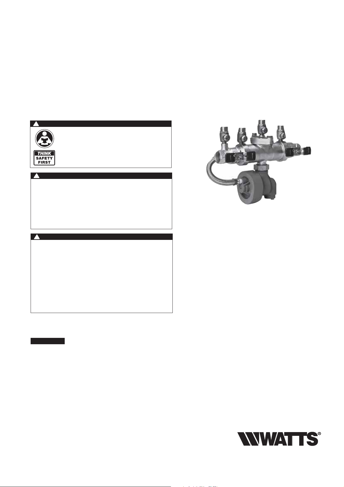
Watts 995 shown
RP/IS-995
!
WARNING
Need for Periodic Inspection/Maintenance: This product
must be tested periodically in compliance with local codes,
but at least once per year or more as service conditions warrant. If installed on a fire suppression system, all mechanical
checks, such as alarms and backflow preventers, should be
flow tested and inspected in accordance with NFPA 13 and/
or NFPA 25. All products must be retested once maintenance
has been performed. Corrosive water conditions and/or
unauthorized adjustments or repair could render the product
ineffective for the service intended. Regular checking and
cleaning of the product’s internal components helps assure
maximum life and proper product function.
NOTICE
For Australia and New Zealand, line strainers should be installed
between the upstream shutoff valve and the inlet of the backflow preventer.
Testing
For field testing procedure, refer to Watts installation sheets
IS-TK-DP/DL, IS-TK-9A, IS-TK-99E and IS-TK-99D found on
watts.com.
For other repair kits and service parts, refer to our Backflow
Prevention Products Repair Kits & Service Parts price list
PL-RP-BPD found on watts.com.
For technical assistance, contact your local Watts representative.
Page 2
Basic Installation Instructions
1
⁄2" - 2" (15 - 50mm)
Indoor Installation
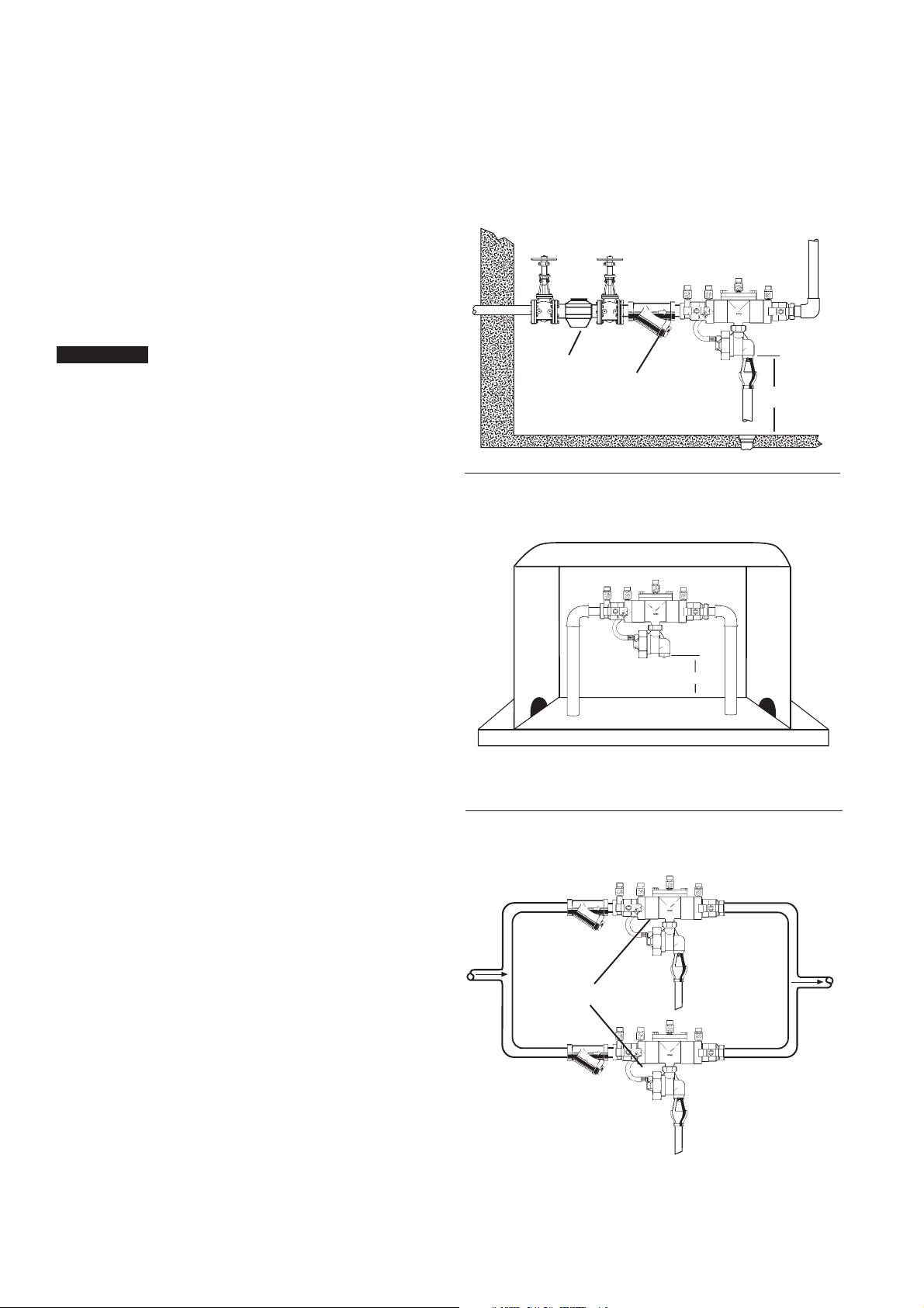
For indoor installations, it is important that the assembly be easily
accessible to facilitate testing and servicing. If it is located in a line
close to wall, be sure the test cocks are easily accessible. A drain
line and air gap should be piped from the relief valve connection as
shown, where evidence of discharge will be clearly visible and so
that water damage will not occur. Therefore, never install in concealed locations.
Outside, Above Ground Installation
NOTICE
Must take precaution to protect against freezing. Temperatures
below 32°F can lead to damage or property loss.
In areas where freezing conditions do not occur, Series 995 can
be installed outside. The most satisfactory installation is above
ground.
In areas where freezing conditions can occur, Series 995 should
be installed above ground in an insulated enclosure.
Series 995 must be installed in an accessible location to facilitate
testing and servicing. A discharge line should be piped from the
air gap at the relief valve connection making sure that there is adequate drainage. Never pipe the discharge line directly into a drainage ditch, sewer or sump. Series 995 should never be installed
where any part of the unit could become submerged in standing
water.
Backflow preventers should never be placed in pits unless
approved by local codes. In such cases, a modified pit installation
is preferred.
Indoor Installation
Meter
Strainer
Outdoor Installation
WattsBox
1" Watts 995QT
with Air Gap
W
12"
W
Watts 995QT
Parallel Installation
Two or more smaller size assemblies can be piped in parallel (when approved) to serve a large supply pipe main. This type
of installation is employed where increased capacity is needed
beyond that provided by a single valve and permits testing or
servicing of an individual valve without shutting down the line completely.
The number of assemblies used in parallel should be determined
by the engineer's judgement based on the operating conditions of
a specific installation.
For parallel valve installations, the total capacity of the assemblies
should equal or exceed that required by the system.
Min. 12"
Now available. WattsBox Insulated Enclosures,
for more information, send for ES-WB or ES-WB-T.
Indoor Installation
995QTS
2
Page 3
Basic Installation Instructions
1
⁄2" - 2" (15 - 50mm)
!
WARNING
A. Series 995 must be installed in a horizontal position.
B. The 995 should always be installed in an accessible location
to facilitate testing and servicing (See page 2). Check the
state and local codes to insure that the backflow preventer is
installed in compliance, such as the proper height above the
ground.
C. We recommend a strainer be installed ahead of 995 series
assemblies to protect the internal components from unnecessary fouling.
!
CAUTION
Do not install with strainer when backflow preventer is used on
seldom-used water lines which are called upon only during
emergencies, such as fire sprinkler lines.
Start Up: The downstream shutoff should be closed. Open
upstream slowly and fill valve. When valve is filled, open the
downstream shutoff slowly and fill the water supply system.
This is necessary to avoid water hammer or shock damage.
D. Water discharge from the relief valve should be vented in
accordance with code requirements. The relief valve should
never be solidly piped into a drainage ditch, sewer or sump.
The discharge should be terminated approximately 12"
(300mm) above the ground or through an air gap piped to a
floor drain.
Depressurize valve before servicing.
NOTICE
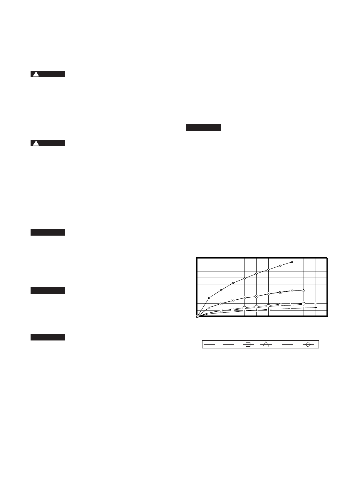
Relief Valve Discharge Rates
The installation of an air gap with the drain line terminating
above a floor drain will handle any normal discharge or nuisance spitting through the relief valve. However, floor drain
size may need to be designed to prevent water damage
caused by a catastrophic failure condition. Please refer to
Figure No. 1 for maximum relief valve discharge rates, size
and capacity of typical floor drains.
NOTICE
Do not reduce the size of the drain line from the air gap fitting.
Pipe full line size.
E. After initial installation, a discharge from the relief valve open-
ing may occur due to inadequate initial flushing of pipe lines
to eliminate dirt and pipe compounds. If flushing will not
clear, remove the first check valve and clean thoroughly.
NOTICE
Periodic relief valve discharge may occur on dead end service
applications, such as boiler feed lines or cooling tower makeup
lines due to fluctuating supply pressure during a static or no
flow condition. To avoid this discharge, install a spring-loaded
check valve ahead of the backflow assembly to “lock-in” the
downstream pressure.
F. Backflow preventers should never be placed in pits unless
absolutely necessary and then only when approved by local
codes. In such cases, provision should be made to always
vent above flood level or for a pit drain to insure an adequate
air gap below the relief port.
G. It is important that Series 995 backflow preventers be
inspected periodically for any discharge from the relief valve
which will provide a visual indication of need for cleaning or
repair of check valves. Also testing for proper operation of
the device should be made periodically in compliance with
local codes, but at least once a year or more often, depending upon system conditions. Send for IS-TK-9A, IS-TK-DP/
DL, S-TK-99E and IS-TK-99D instruction manuals for test
procedures.
Relief vent will discharge water when, during no-flow periods,
(1) the first check valve is fouled or (2) the inlet pressure to the
device drops sufficiently due to upstream pressure fluctuations. Otherwise, such relief (spitting) can occur when the second check is fouled during emergency backflow or resulting
from a water hammer condition. For trouble shooting guide
send for S-TSG.
NOTICE
Special considerations are necessary when testing assemblies
installed on Fire Prevention Systems.
Fire Protection System Installations: The National Fire protec-
tion Agency (NFPA) Guidelines require a confirming flow test
be conducted whenever a “main line” valve such as the shutoff valves or a backflow assembly have been operated.
Certified testers of backflow assemblies must conduct this
confirming test.
Figure 1
Relief Valve Discharge Rates
1
⁄2" - 2" 995
180
160
140
120
100
80
60
40
Flow Rate gpm
20
0
0 10 20 30 40 50 60 70 80 90 100 150
Zone Pressure psi
1
⁄2"1"
3
⁄4"
11⁄4"
1
⁄2"
1
X
2"
*
Typical Flow Rates as sized by
oor drain manufacturers:
2" 55 gpm
3" 112 gpm
4" 170 gpm
3
Page 4
Servicing the Relief Valve
1
⁄2" - 2" (15 - 50mm)
Test Cock No. 2
Test Cock No. 1
Sensing Hose
1st Check
Assembly
Cover
O-ring
Relief Valve Cover Nut
Cover O-ring
Relief Valve Stem/
Diaphragm Assembly
Test Cock No. 3
Cover Bolt (2)
Cover
O-ring
Relief Valve Seat
Seat O-ring
Spring
Test Cock No. 4
2nd Check
Assembly
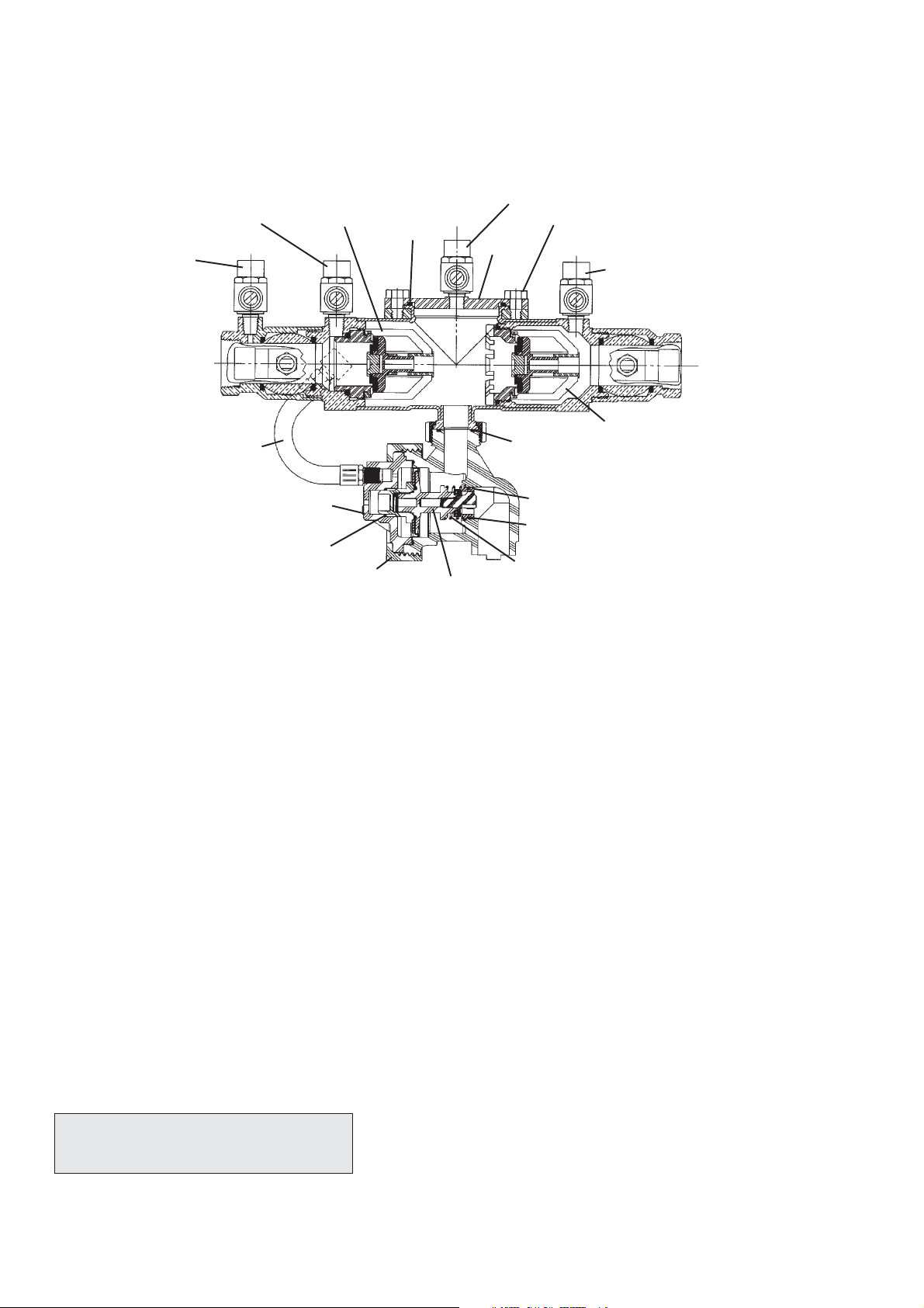
1. Remove the relief valve cover nut by turning the nut counterclockwise
2. Remove the relief valve cover, stem/diaphragm assembly,
and relief valve spring.
3. Inspect the relief valve diaphragm for wear and replace as
needed.
4. The relief valve seat is located inside of the body and can be
removed, if necessary, for cleaning/inspection. The seat is
pressed into the body cavity and can be removed by inserting a finger in the center of the seat and pulling outwards.
Inspect seat for nicks and replace as needed.
For repair kits and parts, refer to our Backflow
Prevention Products Repair Kits & Service Parts
price list PL-RP-BPD found on watts.com.
5. Inspect the disc rubber and clean or replace if required. The
disc can be removed by screwing the white washer counterclockwise.
6. To reassemble the relief valve, press the seat firmly into place
in the body, snap the spring onto the relief valve stem, center the spring on the seat, and insert the cover and stem/
diaphragm assembly as a unit, into the body bore. The
locating pin in the relief valve cover should be aligned with
the corresponding locating notch in the top of the relief valve
body.
7. Install relief valve cover nut and tighten.
4
Page 5
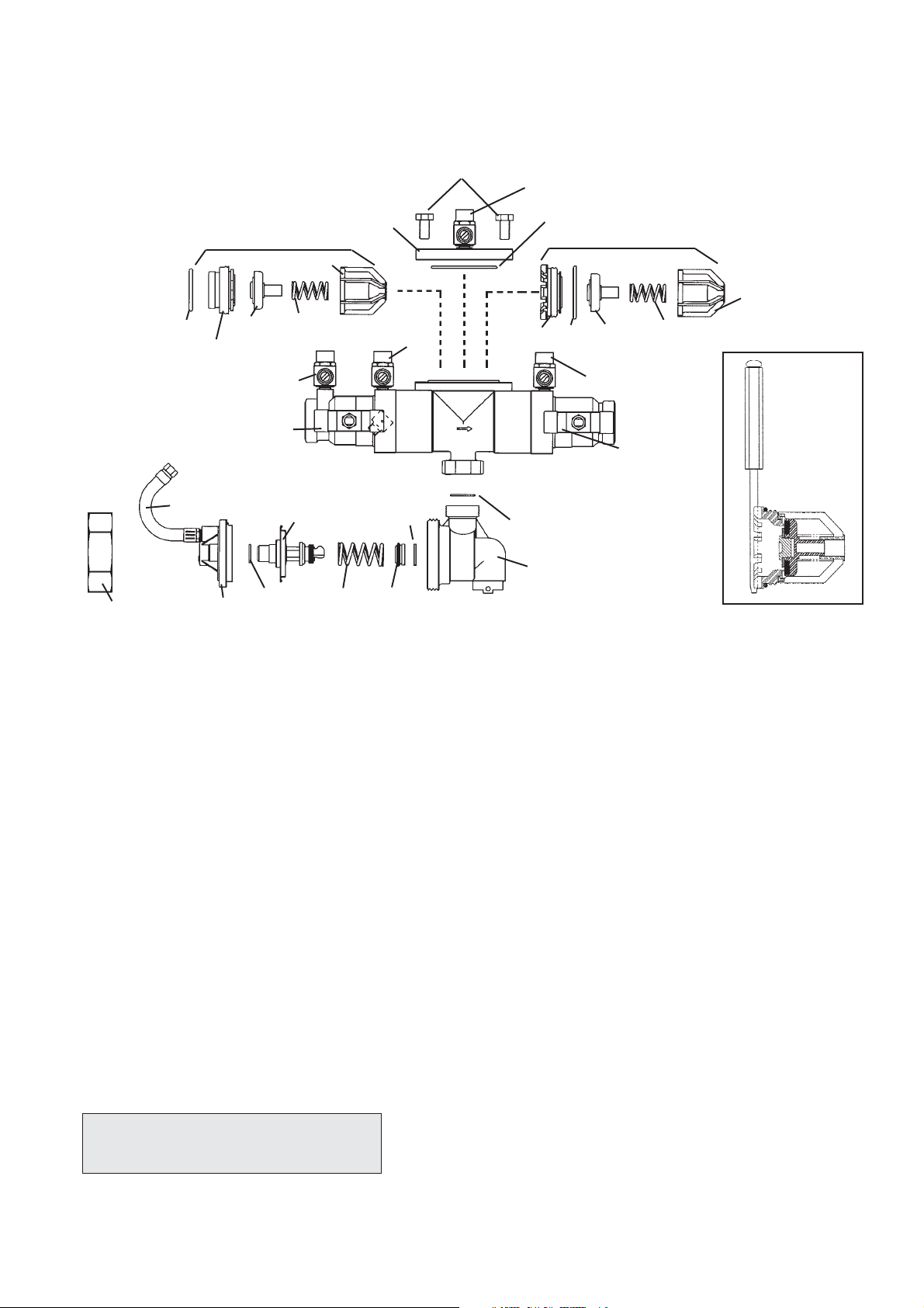
Servicing the First and Second Check Valves
1
⁄2" - 2" (15 - 50mm)
Cover Bolts
Test Cock No. 3
Cover Nut
Seat O-ring
Seat
Sensing
Hose
First Check Assembly
Disc
Assembly
Test Cock No. 1
Shutoff No. 1
Cover
Cage
Spring
Stem/Diaphragm
Assembly
Stem
O-ring
Spring
Cover
Test Cock No. 2
Seat
O-ring
Seat
Cover O-ring
Second Check Assembly
Seat
Seat
O-ring
Relief Valve
Body O-ring
Relief Valve
Body
Disc
Assembly
Test Cock No. 4
Spring
Shutoff No. 2
Cage
2nd Check Removal
Figure 1
1. Close shutoff valves and open test cocks No. 2, 3 and 4 to
relieve pressure from the body of the valve. Loosen cover
bolts and remove cover. The check valve modules can now
be removed from the valve by hand or with a screwdriver.
Note: The first and second check assemblies are not interchangeable and the first check assembly must be removed
prior to removing the second check assembly.
2. The check assemblies are threaded into the valve body. To
remove the first check assembly, rotate the check module by
hand counterclockwise.
3. The second check assembly is removed by inserting the
blade of a screwdriver into two opposing slots of the seat as
shown in Figure 1 and rotate the check assembly counterclockwise.
For repair kits and parts, refer to our Backflow
Prevention Products Repair Kits & Service Parts
price list PL-RP-BPD found on watts.com.
4. The check seats are attached to the cage with a bayonet
type locking arrangement. Holding the cage in one hand,
push the seat inward and rotate clockwise against the cage.
The seat, cage, spring and disc assembly are now individual
components. If the cage disengages prematurely, simply use
the cage as a tool to screw the check valve seat from the
valve body.
5. The disc assembly may now be cleaned and reassembled or,
depending on its condition, it may be replaced with a new
assembly from a repair kit. Seat O-ring should be inspected
and replaced as necessary.
6. Reassemble the check module in the reverse order. Install the
check modules into the valve body hand-tight. Replace the
cover.
5
Page 6
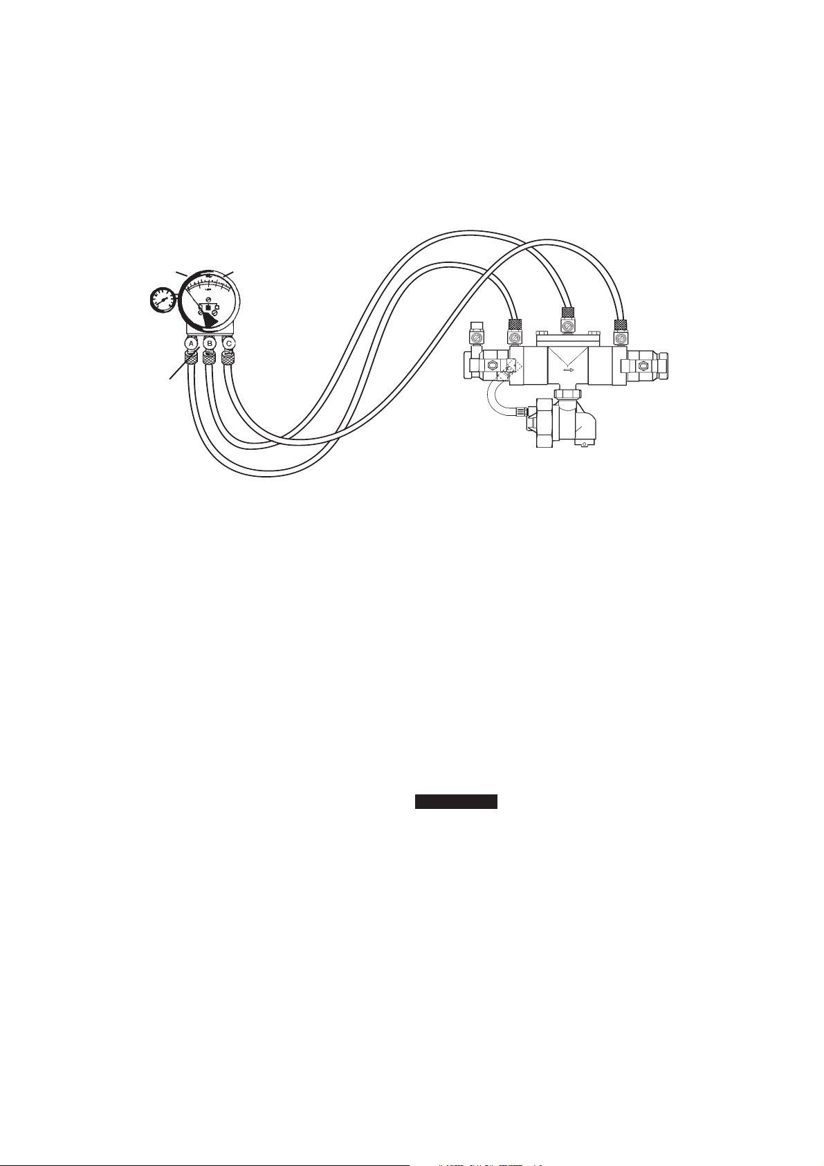
Test Procedure
Test Procedure for Reduced Pressure Assembly
A. All needle valves must be closed on test kit.
B. Open test cock No. 4 and flush test cocks Nos. 1, 2 and 3 on reduced pressure assembly then close test cock No.
4.
C. Attach hoses as shown. Bleed air from kit, close No. 2 shutoff.
Bleed Valve A
Low
(Blue)
High
(red)
Bleed Valve B
Bypass
(yellow)
Test No. 1 - Check Valve No. 2
Purpose: To test check valve No. 2 for tightness against reverse
Requirements: Valve must be tight against reverse flow under all
pres-sure differentials.
Step 1 Slowly open the needle valve “A” high side (red) and “C”
Step 2 Open test cock No. 4. Open test cock No. 2 and test
Step 3 Indicated pressure differential will decrease slightly. If
flow.
bypass (yellow). Keep the “B” low (blue) closed.
cock No. 3 after opening test cock No. 4.
pressure differential continues to decrease (until the vent
opens ) the No. 2 check valve is reported as “leaking”.
Test No. 2 - Shutoff Valve No. 2
Purpose: To test shutoff valve No. 2 for tightness.
Step 1 After passing Test No. 1, continue to test No. 2 by clos-
ing test cock No.2.
Step 2 The indicated pressure differential will decrease slightly. If
pressure differential continues to decrease (approaching
“zero”) the No. 2 shutoff valve is reported to be “leaking”.
Note: A leaking No. 2 shutoff will give a false reading in
tests No. 3 and 4
Test No. 3 - To test No. 1 Check Valve
Purpose: To test check valve No. 1 for tightness.
Requirements: Valve must be tight against reverse flow under all
pressure differentials.
Step 1 Close needle valve “A” high side (red) and open test
cock No. 2.
Step 2 Close test cock No. 4. Disconnect bypass hose (yellow)
at test cock No. 4.
Step 3 Open needle valve “B” low (blue) and “C” bypass (yel-
low), bleeding to atmosphere, then closing needle valve
“B” (blue) restores the system to a normal static condition.
No. 2
Shutoff
995 shown
Step 4 Observe the pressure differential gauge. If there is a
decrease in the indicated value, the No. 1 check valve is
reported as “leaking”.
Test No. 4 - Pressure Differential Relief Valve
Purpose: To test operation of pressure differential relief valve.
Requirements: The pressure differential relief valve must operate
to maintain the “zone” between the two check valves at least 2
psi less than the supply pressure.
Step 1 Close needle valve “C” bypass (yellow).
Step 2 Open needle valve “A” high side (red).
Step 3 Open needle valve “B” low (blue) very slowly until the dif-
ferential gauge needle starts to drop.
Step 4 Hold the valve at this position and observe the gauge
reading at the moment the first discharge is noted from
the relief valve. Record this as the opening differential
pressure of the relief valve.
NOTICE
It is important that the differential gauge needle drops slowly.
Step 5 Close test cocks Nos. 2 and 3. Remove hose from test
cocks Nos. 2 and 3.
Step 6 Use bypass hose (yellow) to relieve pressure from test kit
by opening needle valve “A”, “B” and “C” and bleed
valves “A” and “B”.
Step 7 Remove all test equipment and open No. 2 shutoff valve
of the device.
6
Page 7

Notes
7
Page 8

WARNING: This product contains chemicals known
to the State of California to cause cancer and birth
defects or other reproductive harm.
For more information: www.watts.com/prop65
Limited Warranty: Watts Regulator Co. (the “Company”) warrants each product to be free from defects in material and workmanship under normal usage for a period of one year from the date of
original shipment. In the event of such defects within the warranty period, the Company will, at its option, replace or recondition the product without charge.
THE WARRANTY SET FORTH HEREIN IS GIVEN EXPRESSLY AND IS THE ONLY WARRANTY GIVEN BY THE COMPANY WITH RESPECT TO THE PRODUCT. THE COMPANY MAKES NO OTHER
WARRANTIES, EXPRESS OR IMPLIED. THE COMPANY HEREBY SPECIFICALLY DISCLAIMS ALL OTHER WARRANTIES, EXPRESS OR IMPLIED, INCLUDING BUT NOT LIMITED TO THE IMPLIED
WARRANTIES OF MERCHANTABILITY AND FITNESS FOR A PARTICULAR PURPOSE.
The remedy described in the first paragraph of this warranty shall constitute the sole and exclusive remedy for breach of warranty, and the Company shall not be responsible for any incidental, special
or consequential damages, including without limitation, lost profits or the cost of repairing or replacing other property which is damaged if this product does not work properly, other costs resulting
from labor charges, delays, vandalism, negligence, fouling caused by foreign material, damage from adverse water conditions, chemical, or any other circumstances over which the Company has no
control. This warranty shall be invalidated by any abuse, misuse, misapplication, improper installation or improper maintenance or alteration of the product.
Some States do not allow limitations on how long an implied warranty lasts, and some States do not allow the exclusion or limitation of incidental or consequential damages. Therefore the above
limitations may not apply to you. This Limited Warranty gives you specific legal rights, and you may have other rights that vary from State to State. You should consult applicable state laws to
determine your rights. SO FAR AS IS CONSISTENT WITH APPLICABLE STATE LAW, ANY IMPLIED WARRANTIES THAT MAY NOT BE DISCLAIMED, INCLUDING THE IMPLIED WARRANTIES OF
MERCHANTABILITY AND FITNESS FOR A PARTICULAR PURPOSE, ARE LIMITED IN DURATION TO ONE YEAR FROM THE DATE OF ORIGINAL SHIPMENT.
A Watts Water Technologies Company
Latin America: 5FMt'BYtWatts.com
USA:5FMt'BYt8BUUTDPN
Canada: 5FMt'BYtWatts.ca
RP-IS-995 1444 EDP# 1915236 © 2014 Watts
 Loading...