

Page 1
For Health Hazard Applications
ES-909RPDA
Job Name
Job Location
Engineer
Approval
––––––––––––––––––––––––––––––––––––––––––––
––––––––––––––––––––––––––––––––––––––––––
––––––––––––––––––––––––––––––––––––––––––––––
–––––––––––––––––––––––––––––––––––––––––––––
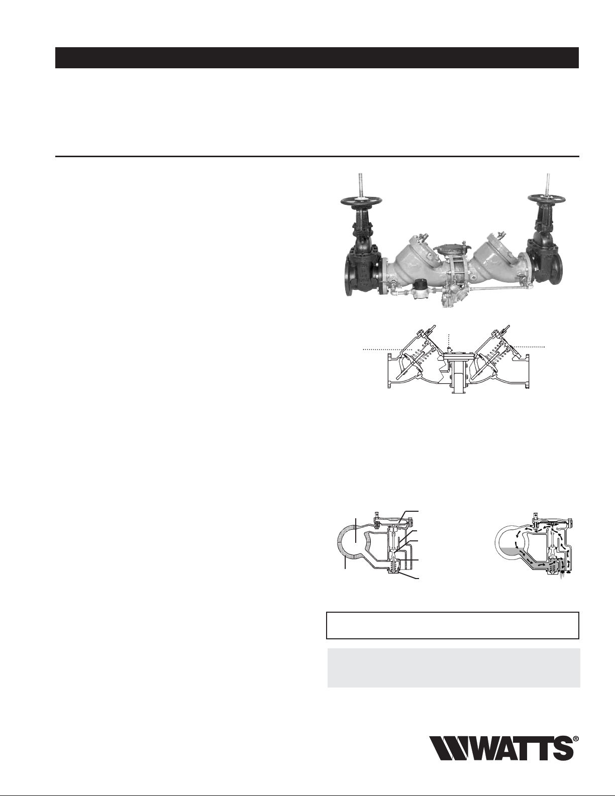
Series 909RPDA
Reduced Pressure Detector
Assemblies
Sizes: 21⁄2" – 10" (65 – 250mm)
Series 909RPDA Reduced Pressure Detector Assemblies are used in health
hazard applications and are designed exclusively for use in accordance with
water utility authority containment requirements. It is mandatory to prevent
the reverse flow of fire protection system substances, i.e., glycerin wetting
agents, stagnant water and water of non-potable quality from being pumped
or siphoned into the potable water line.
Benefits: Detects leaks ...with emphasis on the cost of unaccountable water;
incorporates a meter which allow the water utility to:
• detect leaks that historically create great annual cost due to waste
• provide a detection point for unauthorized use. It can help locate illegal taps
Modular check design concept facilitates maintenance and assembly access.
All sizes are standardly equipped with AWWA epoxy coated, UL/FM listed OSY
resilient seated gate valves, CFM (cubic feet per minute) or GPM (gallon per
minute) meter and ball type test cocks. A pressure differential relief valve is
located in a zone between the check valves.
Modular Design
Features a modular design concept which facilitates maintenance and
assembly access. All sizes are standardly equipped with gate valves and ball
type test cocks.
Features
• Body construction fused epoxy coated cast iron
• Replaceable bronze seats
• Maximum flow at low pressure drop
• Compact for economy combined with performance
• Design simplicity for easy maintenance
• Furnished with
• Air-in/Water-out relief valve design provides maximum capacity during
emergency conditions.
• No special tools required
Specifications
A Reduced Pressure Detector Assembly shall be installed on fire protection
systems when connected to a public water supply. Degree of hazard present
is determined by the local authority having jurisdiction. The unit shall be a
complete assembly including UL listed and FM approved OSY shutoff valves.
Including an auxiliary line consisting of an approved backflow preventer and
water meter. The assembly shall meet the requirements of AWWA C511-92;
ASSE 1047; UL Classified File No. EX3185; CSA B64 and USC Manual 8th.
Edition. Assembly shall be a Watts Regulator Company Series 909RPDA.
5
⁄8" x 3⁄4" (16 x 19mm) meter
Contractor
Approval
Contractor’s P.O. No.
Representative
909RPDAOSY
First
Check
Assembly
––––––––––––––––––––––––––––––––––––––––––––
––––––––––––––––––––––––––––––––––––––––––––––
–––––––––––––––––––––––––––––––––––
–––––––––––––––––––––––––––––––––––––––––
Relief Valve
Second
Check
Assembly
How it operates
The unique relief valve construction incorporates two channels: one for air,
one for water. When the relief valve opens, as in the accompanying airin/water-out diagram, the right-hand channel admits air to the top of the
reduced pressure zone, relieving the zone vacuum. The channel on the left
then drains the zone to atmosphere. Therefore, if both check valves foul, and
simultaneous negative supply and positive backpressure develops, the relief
valve uses the air-in/water-out principle to stop potential backflow.
Pipe Line
Center
Relief Valve
Body Flange
IMPORTANT: INQUIRE WITH GOVERNING AUTHORITIES
Relief Valve Seat
Relief Valve Piston
Relief Valve
Piston Assembly
Wiper Seal
Bottom Plug
Spring Assembly
FOR LOCAL INSTALLATION REQUIREMENTS
Water Air
Out In
Now Available
WattsBox Insulated Enclosures.
For more information, send for literature ES-WB.
Watts product specifications in U.S. customary units and metric are approximate and are provided for reference only. For precise measurements,
please contact Watts Technical Service. Watts reserves the right to change or modify product design, construction, specifications, or materials without prior notice and without incurring any obligation to make such changes and modifications on Watts products previously or subsequently sold.
Page 2
Models
Suffix:
OSY – UL/FM outside stem and yoke resilient seated gate valves
CFM – cubic feet per minute meter
GPM – gallons per minute meter
LF – less shutoff valves
Standards
AWWA C511-92; CSA B64
USC Manual for Cross-connection Control, 8th Edition
Approvals
Materials
Discs: Rubber
Body: Epoxy coated cast iron
Seat and Disc Holder: Bronze
Trim: Stainless steel
Test Cocks: Bronze
Pressure — Temperature
Temperature Range: 33°F – 140°F (0.5°C – 60°C) continuous
Maximum Working Pressure: 175psi (12.1 bar)
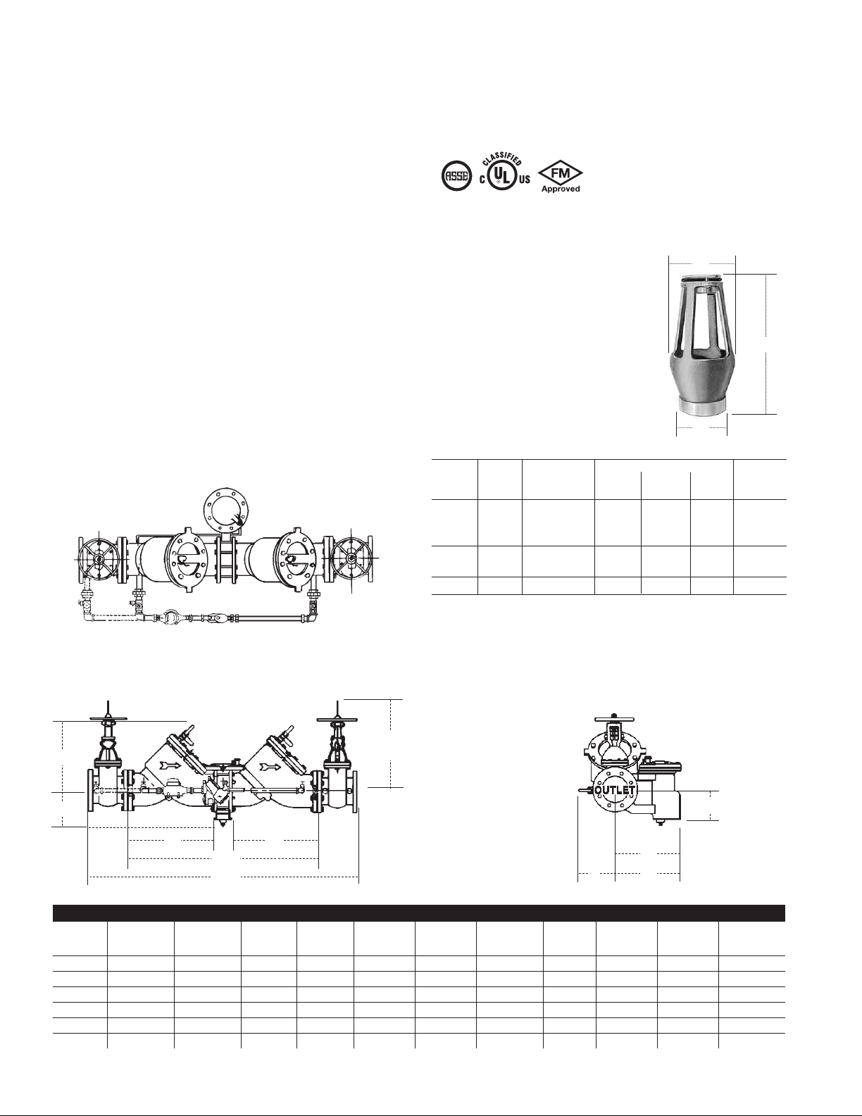
Dimensions — Weights
1047
Approved by the foundation for Cross-Connection Control and Hydraulic
Research at the University of Southern California.
A
Series 909AG AIR GAPS
When installing a drain line, use Series 909
air gaps on Model 909 backflow preventers.
B
C
Iron Ordering Series/Sizes Dimensions Weight
Body Code A B C
Model in. mm in. mm in. mm lbs kgs
909AG-F 0881378 11⁄4" – 3" 009/909
909AG-K 0881385 4" – 6" 909 63⁄8" 162 95⁄8244 3 76 6.25 2.83
909AG-M 0881387 8" – 10" 909 73⁄8" 187 111⁄4286 4 102 15.50 7.03
1
⁄4" – 2" 009 M1 43⁄8" 111 63⁄4171 2 51 3.25 1.47
1
2" 009 M2
8" – 10" 909 M1
NOTE: Piping for 3" 909 will start from #1 gate valve and connect
at #2 check valve.
C
G
D
E1
L
A
SIZE (DN) DIMENSIONS WEIGHT
ACDD1E,E1GLRTT1
in. mm in. mm in. mm in. mm in. mm in. mm in. mm in. mm in. mm in. mm in. mm lbs. kgs.
21⁄265 421⁄81070 163⁄8416 51⁄4133 41⁄4114 12 305 7 178 261⁄8664 14 356 9 229 75⁄8194 230 104
380421⁄81070 187⁄8479 51⁄4133 41⁄4114 12 305 7 178 261⁄8664 14 356 9 229 75⁄8194 230 104
4 100 551⁄81400 223⁄4578 6 152 57⁄8149 17 432 91⁄2241 37 940 15 381 135⁄8346 113⁄4299 470 213
6 150 66 1664 301⁄8765 6 152 6 152 203⁄4527 141⁄2368 45 1130 16 406 135⁄8346 113⁄4299 798 362
8 200 781⁄21994 373⁄4959 93⁄4248 85⁄8219 26 660 181⁄2470 551⁄41403 17 432 181⁄2470 163⁄8416 1456 660
10 250 935⁄82378 453⁄41162 93⁄4248 85⁄8219 32 813 211⁄2546 671⁄21715 18 457 181⁄2470 163⁄8416 2230 1012
E
(Open)
D1
T1
R
T
2
Page 3

Capacity
*Typical maximum flow rate (7.5 feet/sec.) **UL rated flow
1
⁄2" (65mm)
kPa psi
207 30
172 25
138 20
103 15
69 10
35 5
00
0 20 40 60 80 100 120 140 160 180 200 220 240 gpm
0 76 152 228 304 380 456 532 608 684 760 836 912 lpm
ΔP
2
*
6 7.5 10 15 fps
1.8 2.3 3.0 4.6 mps
4" (100mm)
kPa psi
207 30
172 25
138 20
103 15
69 10
35 5
00
0 50 100 150 200 250 300 350 400 450 500 550 600 gpm
ΔP
0 190 380 50 760 950 1140 1330 1520 1710 1900 2090 2280 lpm
5 7.5 10 15 fps
1.5 2.3 3.0 4.6 mps
*
**
**
kPa psi
207 30
172 25
138 20
103 15
69 10
35 5
00
0 30 60 90 120 150 180 210 240 270 300 330 360 gpm
ΔP
0 114 228 342 456 570 684 798 912 1026 1140 1254 1368 lpm
kPa psi
207 30
172 25
138 20
103 15
69 10
35 5
00
0 200 400 600 800 1000 1200 1400 1600 gpm
ΔP
0 700 1520 2280 3040 3800 4560 5320 6080 lpm
6" (150mm)
5 7.5 10 15 fps
1.5 2.3 3.0 4.6 mps
5 7.5 10 15 fps
1.5 2.3 3.0 4.6 mps
*
*
**
3" (80mm)
**
kPa psi
207 30
172 25
138 20
103 15
69 10
35 5
00
0 200 400 600 800 1000 1200 1400 1600 1800 2000 gpm
ΔP
0 760 1520 2280 3040 3800 4560 5320 6080 6840 7600 lpm
5 7.5 10 fps
1.5 2.3 3.0 mps
*
**
8" (200mm)
10" (250mm)
kPa psi
207 30
172 25
138 20
103 15
69 10
35 5
00
0 250 500 750 1000 1250 1500 1750 2000 2250 2500 2750 3000 gpm
ΔP
0 950 1900 2850 3800 4750 5700 6650 7600 8550 9500 10450 11400 lpm
6 7.5 10 fps
1.8 2.3 3.0 mps
*
**
3
Page 4

For additional information, visit our web site at: www.watts.com
A Watts Water Technologies Company
Canada: 5435 North Service Rd., Burlington, ONT. L7L 5H7; www.wattscanada.ca
ES-909RPDA 1004 © 2010 Watts
USA: 815 Chestnut St., No. Andover, MA 01845-6098; www.watts.com
 Loading...