

Page 1
For Commercial and Institutional Applications
ES-77F-DI-250
Job Name
Job Location
Engineer
Approval
LEAD FREE
–––––––––––––––––––––––––––––––––––––––––––
–––––––––––––––––––––––––––––––––––––––––
–––––––––––––––––––––––––––––––––––––––––––––
–––––––––––––––––––––––––––––––––––––––––––––
*
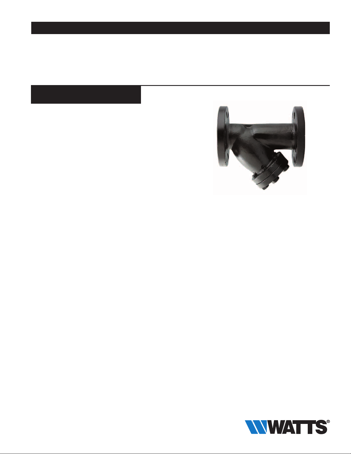
Series 77F-DI-250
Flanged, Wye Pattern, Ductile Iron
Strainers
Sizes: 2" – 12" (50 – 300mm)
Series 77F-DI-250 Flanged, Wye Pattern, Ductile Iron Strainers
feature a one-piece cast body, bolted cover flange with flat gasket
seal, 304 stainless steel perforated screens and a drain/blow-off
connection plug.
Features
• Flanges conform to American Cast Iron Flange Standard, Class
250 (ANSI B16.1)
• Body meets ASME standards
• One-piece lead free* cast body
• Equipped with bolted cover flange that utilizes a flat gasket seal
• Upper and lower machined seats
• 304 Stainless steel perforated screens
• Drain/Blow-off connection furnished with plug
• Generous screen area and properly proportioned straining
chamber to minimize initial pressure drop while maximizing time
between cleanings
Specifications
A flanged, wye pattern, ductile iron strainer to be installed as indicated on the plans. The strainer must have a one-piece cast body,
bolted cover flange, machined seats, 304 stainless steel perforated
screens and a drain/blow-off plug. Pressure rating no less than
500psi (34.47 bars) WOG non-shock and 250psi (17.2 bars) WSP.
Strainer body and flanges shall conform to American Cast Iron
Flange Standard, Class 250 (ANSI B16.1). Strainer shall be a Watts
Series 77F-DI-250.
Contractor
Approval
Contractor’s P.O. No.
Representative
––––––––––––––––––––––––––––––––––––––––––––
–––––––––––––––––––––––––––––––––––––––––––––
––––––––––––––––––––––––––––––––––––––––
77F-DI-250
Pressure – Temperature
Temperature Range: -20°F (-28.9°C) - 406°F (208°C)
Maximum Operating Pressure:
500psi (34.47 bars) WOG, non-shock, @ 150°F (66°C)
250psi (17.2 bars) WSP @ 406°F (208°C)
Standard Screens
2" – 3" (50 – 75mm): 3/64" perforation
4" – 12" (100 – 300mm):
––––––––––––––––––––––––––––––––––
1
/8" perforation
*The wetted surface of this product contacted by consumable
water contains less than 0.25% of lead by weight.
Watts product specifications in U.S. customary units and metric are approximate and are provided for reference only. For precise measurements,
please contact Watts Technical Service. Watts reserves the right to change or modify product design, construction, specifications, or materials without prior notice and without incurring any obligation to make such changes and modifications on Watts products previously or subsequently sold.
Page 2
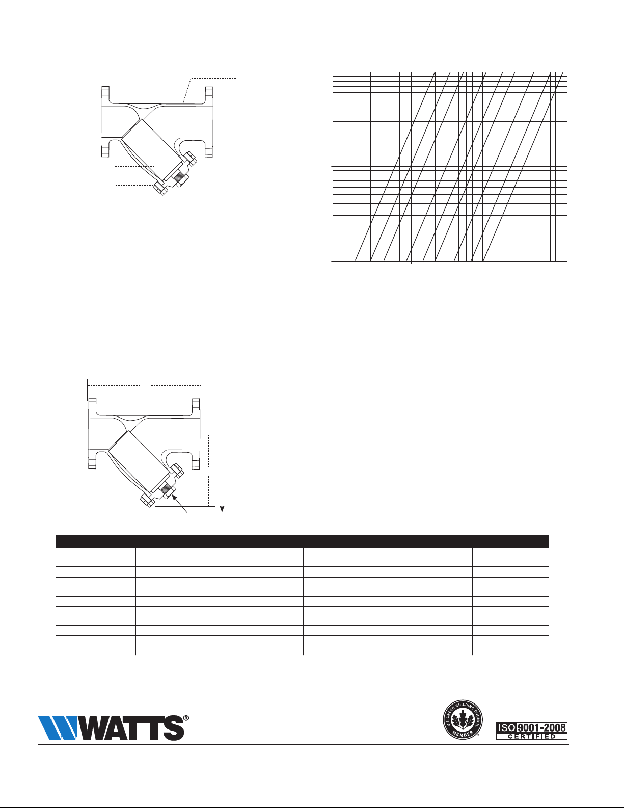
Materials
C
E
A Body Ductile Iron A395
B Cover Ductile Iron A395
C Screen 304 Stainless Steel
D Plug Cast Iron, A126-B
E Bolt/Stud A307-B
F Nut A563
Pressure Drop vs. Flow
”
2
kPa psi
A
69 10
Pressure Drop
B
7 1.0
D
F
1 0.1
10 100 1000 10000 gpm
38 380 3800 38000 lpm
2”
Flow
⁄
1
2
4”
3”
5”
8”
10”
6”
12”
Dimensions
— Weights
A
D
Clearance
B
for screen
removal
C NPT
SIZE (DN) DIMENSIONS WEIGHT
A B C D
in. mm in. mm in. mm in. mm in. mm lbs. kgs
2 50 87⁄8 226 61/2 165 1/2 15 91/8 232 28 13
2
3 75 11
4 100 14
5 125 17
6 150 18
8 200 21
10 250 27
12 300 31
1
⁄2 65 111⁄4 289 7 178 1 25 97/8 251 38 17
5
⁄8 295 8 203 1 25 111/4 286 54 24
1
⁄2 368 103⁄4 273 1 25 15 381 110 50
3
⁄8 441 131/2 343 11/4 32 19 483 160 73
3
/4 476 161/4 413 11/2 40 223/4 578 224 102
7
/8 556 191/2 495 11/2 40 273/4 692 468 212
1
/4 692 211/4 540 2 50 293/4 756 590 268
3
/8 797 25 635 2 50 35 889 890 404
A Watts Water Technologies Company
USA: Tel: (978) 688-1811 • Fax: (978) 794-1848 • www.watts.com
Canada: Tel: (905) 332-4090 • Fax: (905) 332-7068 • www.watts.ca
ES-77F-DI-250 1307 © 2013 Watts
 Loading...