

Page 1
Installation, Maintenance, & Repair
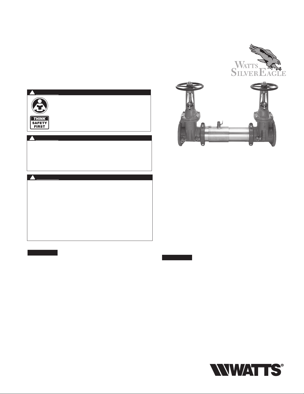
Series 757, 757DCDA & LF757DCDA
Double Check Valve Assemblies
Double Check Detector Assemblies
Sizes: 21⁄2" – 10" (65 – 250mm)**
!
WARNING
Read this Manual BEFORE using this equipment.
Failure to read and follow all safety and use information can
result in death, serious personal injury, property damage, or
damage to the equipment.
Keep this Manual for future reference.
!
WARNING
You are required to consult the local building and plumbing
codes prior to installation. If the information in this manual
is not consistent with local building or plumbing codes,
the local codes should be followed. Inquire with governing
authorities for additional local requirements.
!
WARNING
Need for Periodic Inspection/Maintenance: This product must
be tested periodically in compliance with local codes, but at least
once per year or more as service conditions warrant. If installed on
a fire suppression system, all mechanical checks, such as alarms
and backflow preventers, should be flow tested and inspected in
accordance with NFPA 13 and/or NFPA 25. All products must be
retested once maintenance has been performed. Corrosive water
conditions, and/or unauthorized adjustments or repair could render
the product ineffective for the service intended. Regular checking
and cleaning of the product’s internal components helps assure
maximum life and proper product function.
NOTICE
For Australia and New Zealand, line strainers should be installed
between the upstream shutoff valve and the inlet of the backflow preventer.
Installation Guidelines
Most field problems occur because dirt and debris present in the
system at the time of installation become trapped in the #1 check.
The system should be flushed before the backflow valve is
installed. If the system is not flushed until after the backflow valve
is installed, remove both check modules from the valve and open
the inlet shutoff to allow water to flow for a sufficient time to flush
debris from the water line. If debris in the water system continues
to cause fouling, a strainer can be installed upstream of the backflow assembly.
Watts Series 757 and 757DCDA/LF757DCDA may be installed in
either horizontal or vertical position as long as the backflow assembly is installed in accordance with the direction of the flow arrow
on the assembly and the local water authority approves the installation. The assembly should be installed with adequate clearance
around the valve to allow for inspection, testing and servicing. 12"
should be the minimum clearance between the lower portion of the
assembly and the floor or grade.
NOTICE
Assembly body should not be painted.
757 OSY
RP/IS-757/757DCDA
®
Testing
For field testing procedure, refer to Watts installation sheets
IS-TK-DP/DL, IS-TK-9A, IS-TK-99E and IS-TK-99D found on
www.watts.com.
For other repair kits and service parts, refer to our Backflow
Prevention Products Repair Kits & Service Parts price list
PL-RP-BPD found on www.watts.com.
For technical assistance, contact your local Watts representative.
** Metric Dimensions are nominal pipe diameter. This product is
produced with ASME/ANSI flanged end connections.
Page 2
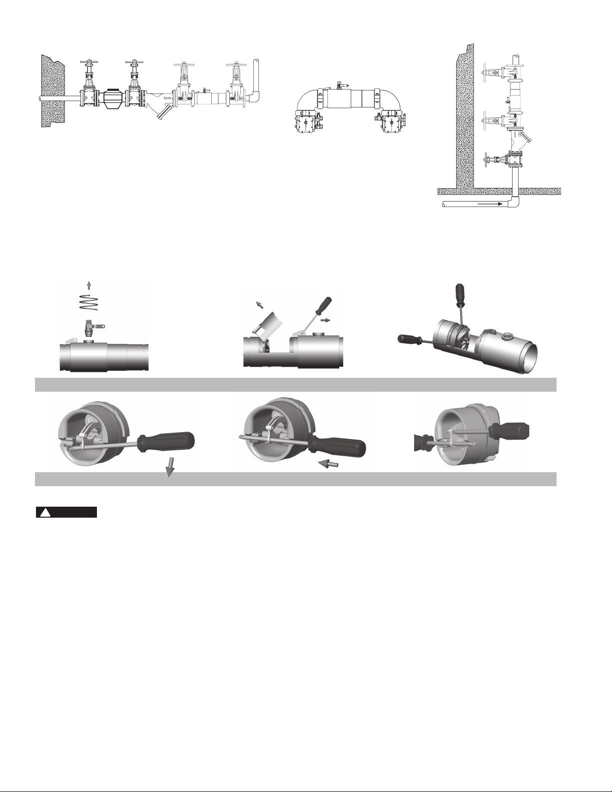
Horizontal Installation
Maintenance Instructions
21/2" – 6" (65 – 150mm)
Vertical
Installation
N Pattern
Figure A
Figure D
!
WARNING
Prior to servicing any Watts valve, it is mandatory to shut down
the water system by closing both the inlet and outlet shutoff
valves. After shutoff valves are closed, open test cock #2, #3
and #4 to relieve pressure within the backflow assembly.
1. After #3 test cock has been opened to relieve pressure,
remove #3 test cock from housing. (Figure A)
2. Insert a #3 screwdriver through the hole on the top of the
cover sleeve and using both hands rotate the cover sleeve
approximately
wise to break the sleeve O-ring seals. Using the screwdriver,
slowly slide the cover sleeve to the downstream side of the
housing. (Figure B)
3. Remove the stainless steel check retainer from the housing.
(Figure B)
4. Remove the #1 check module (Figure C) by inserting two flat
blade screwdrivers into the slots on either side of the check
module and gently pry the check module toward the open
zone.
5. Remove #2 check module with the same instructions as in #4
above. For servicing 6" (150mm) checks, see 8" – 10" (200 –
250mm) instructions on p. 3.
1
/4-turn clockwise and 1/4-turn counterclock-
Figure E
Figure B
6. To clean or inspect either check module, insert a #3 screwdriver through the downstream side of the check module as
shown in Figure D and E. When the screwdriver is in place,
remove the E-clip (Figure F) and pin connecting the structural
members and the check clapper will open with no tension.
7. Thoroughly clean the seating area. The sealing disc may be
removed, if necessary, by removing the screws connecting
the keeper plate to the clapper. The sealing disc may be
reversed and reinstalled if the elastomer is cut or damaged.
8. Wash check module and O-ring and inspect for any damage.
If damaged, reinstall new parts.
9. After thorough cleaning, lubricate O-ring w/FDA approved
lubricant, replace pin and E-clip in structural members,
remove screw driver and reinstall check modules and assemble housing in reverse order of these instructions.
Figure C
Figure F
2
Page 3

Maintenance Instructions
Series 757, 757DCDA & LF757DCDA
8" – 10" (200 – 250mm)
Material/Tool Requirements:
• #3Phillipsscrewdriveror5/16" diameter rod, length sufficient
to span diameter of check, see Figures A and B.
1
•
/2" – 13 x 5" fully threaded hex bolt (Service bolt).
3
•
/4" open end or socket wrench.
Instructions:
!
WARNING
Prior to servicing any Watts valve, it is mandatory to shut
down the water system by closing both the inlet and outlet
shutoff valves. After shutoff valves are closed, open test
cock #2, #3 & #4 to relieve pressure within the backflow
assembly.
1. After #3 test cock has been opened to
relieve pressure, remove #3 test cock from housing. When
repairing an 8" or 10" (200 – 250mm) device, remove both
Victaulic couplers from body. Slide the downstream Victaulic
coupler gasket to the downstream side of the housing. The
upstream Victaulic coupler gasket stays in place.
2. Remove check/s to be serviced.
3. Locate the service hole and thread in the service bolt by hand
until it contacts the linkage. (Figure A)
4. Continue to thread in service bolt with the wrench until the
service hole in the linkage is aligned with the service notches
on the spring arbors. (Figure A)
5. Insert the Phillips screwdriver through the arbors and service
hole of the linkage making sure that the tip of the screwdriver
extends past the ends of the arbors by a minimum of
(6mm). (Figure B)
6. Back out the service bolt until load is transferred to the screwdriver. Continue to back out the service bolt until sufficient
clearance is achieved to remove the complete spring mechanism.
7. To disconnect linkage, remove retaining clip and pin (store in
a safe location for reinstallation).
8. To remove spring mechanism, grasp the screwdriver at the
center and pull complete assembly straight out and store in
a safe place.
9. Reinstall in reverse order.
!
WARNING
While the spring mechanism is removed for check servicing;
never pull the screwdriver out or off the support notches on the
arbors. Doing so may cause bodily injuries.
1
/4"
Service Hole
Sleeve O-ring
and Gasket
Check Module
O-ring
First Check Module
Figure A
Second Check Module
Figure B
Closure Sleeve Test Cock
with O-ring
Closure Sleeve
E-clip
Disc Elastomer
For repair kits and parts, refer to Backflow
Prevention Products Repair Kits & Service Parts
price list PL-RP-BPD on www.watts.com
3
Page 4

Troubleshooting Guide
Series 757, 757DCDA & LF757DCDA
Problem Cause Solution
1. Check valve fails to hold
1.0 PSID minimum
2. Chatter during flow conditions a. Worn, damaged or defective guide Disassemble and repair or replace guide
3. Low flows passing through
mainline valve
a. Debris on check disc sealing surface Disassemble and clean
b. Leaking gate valve Disassemble and clean or repair
c. Damaged seat disc or seat o-ring Disassemble and replace
d. Damaged guide holding check open Disassemble and clean or replace
e. Weak or broken spring Disassemble and replace spring
a. Mainline check fouled Disassemble and clean
b. Meter strainer plugged Disassemble and clean
c. Damaged mainline seat disc or seat Disassemble and replace
d. Broken mainline spring Disassemble and replace
WARNING: This product contains chemicals known to the
State of California to cause cancer and birth defects or
other reproductive harm.
For more information: www.watts.com/prop65
Limited Warranty: Watts Regulator Co. (the “Company”) warrants each product to be free from defects in material and workmanship under normal usage for a period of one year from the date of
original shipment. In the event of such defects within the warranty period, the Company will, at its option, replace or recondition the product without charge.
THE WARRANTY SET FORTH HEREIN IS GIVEN EXPRESSLY AND IS THE ONLY WARRANTY GIVEN BY THE COMPANY WITH RESPECT TO THE PRODUCT. THE COMPANY MAKES NO OTHER
WARRANTIES, EXPRESS OR IMPLIED. THE COMPANY HEREBY SPECIFICALLY DISCLAIMS ALL OTHER WARRANTIES, EXPRESS OR IMPLIED, INCLUDING BUT NOT LIMITED TO THE IMPLIED
WARRANTIES OF MERCHANTABILITY AND FITNESS FOR A PARTICULAR PURPOSE.
The remedy described in the first paragraph of this warranty shall constitute the sole and exclusive remedy for breach of warranty, and the Company shall not be responsible for any incidental, special
or consequential damages, including without limitation, lost profits or the cost of repairing or replacing other property which is damaged if this product does not work properly, other costs resulting
from labor charges, delays, vandalism, negligence, fouling caused by foreign material, damage from adverse water conditions, chemical, or any other circumstances over which the Company has no
control. This warranty shall be invalidated by any abuse, misuse, misapplication, improper installation or improper maintenance or alteration of the product.
Some States do not allow limitations on how long an implied warranty lasts, and some States do not allow the exclusion or limitation of incidental or consequential damages. Therefore the above
limitations may not apply to you. This Limited Warranty gives you specific legal rights, and you may have other rights that vary from State to State. You should consult applicable state laws to
determine your rights. SO FAR AS IS CONSISTENT WITH APPLICABLE STATE LAW, ANY IMPLIED WARRANTIES THAT MAY NOT BE DISCLAIMED, INCLUDING THE IMPLIED WARRANTIES OF
MERCHANTABILITY AND FITNESS FOR A PARTICULAR PURPOSE, ARE LIMITED IN DURATION TO ONE YEAR FROM THE DATE OF ORIGINAL SHIPMENT.
A Watts Water Technologies Company
RP/IS-757/757DCDA 1341 EDP# 1915343 © 2013 Watts
USA:Tel:(978)688-1811•Fax:(978)794-1848•www.watts.com
Canada: Tel:(905)332-4090•Fax:(905)332-7068•www.watts.ca
 Loading...